EP2182375A1 - A combined direction finder and radar system, method and computer program product - Google Patents
A combined direction finder and radar system, method and computer program product Download PDFInfo
- Publication number
- EP2182375A1 EP2182375A1 EP08167955A EP08167955A EP2182375A1 EP 2182375 A1 EP2182375 A1 EP 2182375A1 EP 08167955 A EP08167955 A EP 08167955A EP 08167955 A EP08167955 A EP 08167955A EP 2182375 A1 EP2182375 A1 EP 2182375A1
- Authority
- EP
- European Patent Office
- Prior art keywords
- antenna elements
- receiving
- receiving antenna
- received
- signals
- Prior art date
- Legal status (The legal status is an assumption and is not a legal conclusion. Google has not performed a legal analysis and makes no representation as to the accuracy of the status listed.)
- Withdrawn
Links
Images






Classifications
-
- G—PHYSICS
- G01—MEASURING; TESTING
- G01S—RADIO DIRECTION-FINDING; RADIO NAVIGATION; DETERMINING DISTANCE OR VELOCITY BY USE OF RADIO WAVES; LOCATING OR PRESENCE-DETECTING BY USE OF THE REFLECTION OR RERADIATION OF RADIO WAVES; ANALOGOUS ARRANGEMENTS USING OTHER WAVES
- G01S13/00—Systems using the reflection or reradiation of radio waves, e.g. radar systems; Analogous systems using reflection or reradiation of waves whose nature or wavelength is irrelevant or unspecified
- G01S13/86—Combinations of radar systems with non-radar systems, e.g. sonar, direction finder
-
- G—PHYSICS
- G01—MEASURING; TESTING
- G01S—RADIO DIRECTION-FINDING; RADIO NAVIGATION; DETERMINING DISTANCE OR VELOCITY BY USE OF RADIO WAVES; LOCATING OR PRESENCE-DETECTING BY USE OF THE REFLECTION OR RERADIATION OF RADIO WAVES; ANALOGOUS ARRANGEMENTS USING OTHER WAVES
- G01S3/00—Direction-finders for determining the direction from which infrasonic, sonic, ultrasonic or electromagnetic waves, or particle emission, not having a directional significance, are being received
- G01S3/02—Direction-finders for determining the direction from which infrasonic, sonic, ultrasonic or electromagnetic waves, or particle emission, not having a directional significance, are being received using radio waves
- G01S3/14—Systems for determining direction or deviation from predetermined direction
- G01S3/46—Systems for determining direction or deviation from predetermined direction using antennas spaced apart and measuring phase or time difference between signals therefrom, i.e. path-difference systems
- G01S3/48—Systems for determining direction or deviation from predetermined direction using antennas spaced apart and measuring phase or time difference between signals therefrom, i.e. path-difference systems the waves arriving at the antennas being continuous or intermittent and the phase difference of signals derived therefrom being measured
-
- G—PHYSICS
- G01—MEASURING; TESTING
- G01S—RADIO DIRECTION-FINDING; RADIO NAVIGATION; DETERMINING DISTANCE OR VELOCITY BY USE OF RADIO WAVES; LOCATING OR PRESENCE-DETECTING BY USE OF THE REFLECTION OR RERADIATION OF RADIO WAVES; ANALOGOUS ARRANGEMENTS USING OTHER WAVES
- G01S13/00—Systems using the reflection or reradiation of radio waves, e.g. radar systems; Analogous systems using reflection or reradiation of waves whose nature or wavelength is irrelevant or unspecified
- G01S13/02—Systems using reflection of radio waves, e.g. primary radar systems; Analogous systems
- G01S13/06—Systems determining position data of a target
- G01S13/08—Systems for measuring distance only
- G01S13/32—Systems for measuring distance only using transmission of continuous waves, whether amplitude-, frequency-, or phase-modulated, or unmodulated
- G01S13/34—Systems for measuring distance only using transmission of continuous waves, whether amplitude-, frequency-, or phase-modulated, or unmodulated using transmission of continuous, frequency-modulated waves while heterodyning the received signal, or a signal derived therefrom, with a locally-generated signal related to the contemporaneously transmitted signal
-
- G—PHYSICS
- G01—MEASURING; TESTING
- G01S—RADIO DIRECTION-FINDING; RADIO NAVIGATION; DETERMINING DISTANCE OR VELOCITY BY USE OF RADIO WAVES; LOCATING OR PRESENCE-DETECTING BY USE OF THE REFLECTION OR RERADIATION OF RADIO WAVES; ANALOGOUS ARRANGEMENTS USING OTHER WAVES
- G01S3/00—Direction-finders for determining the direction from which infrasonic, sonic, ultrasonic or electromagnetic waves, or particle emission, not having a directional significance, are being received
- G01S3/02—Direction-finders for determining the direction from which infrasonic, sonic, ultrasonic or electromagnetic waves, or particle emission, not having a directional significance, are being received using radio waves
- G01S3/74—Multi-channel systems specially adapted for direction-finding, i.e. having a single antenna system capable of giving simultaneous indications of the directions of different signals
-
- G—PHYSICS
- G01—MEASURING; TESTING
- G01S—RADIO DIRECTION-FINDING; RADIO NAVIGATION; DETERMINING DISTANCE OR VELOCITY BY USE OF RADIO WAVES; LOCATING OR PRESENCE-DETECTING BY USE OF THE REFLECTION OR RERADIATION OF RADIO WAVES; ANALOGOUS ARRANGEMENTS USING OTHER WAVES
- G01S7/00—Details of systems according to groups G01S13/00, G01S15/00, G01S17/00
- G01S7/02—Details of systems according to groups G01S13/00, G01S15/00, G01S17/00 of systems according to group G01S13/00
- G01S7/021—Auxiliary means for detecting or identifying radar signals or the like, e.g. radar jamming signals
-
- G—PHYSICS
- G01—MEASURING; TESTING
- G01S—RADIO DIRECTION-FINDING; RADIO NAVIGATION; DETERMINING DISTANCE OR VELOCITY BY USE OF RADIO WAVES; LOCATING OR PRESENCE-DETECTING BY USE OF THE REFLECTION OR RERADIATION OF RADIO WAVES; ANALOGOUS ARRANGEMENTS USING OTHER WAVES
- G01S13/00—Systems using the reflection or reradiation of radio waves, e.g. radar systems; Analogous systems using reflection or reradiation of waves whose nature or wavelength is irrelevant or unspecified
- G01S13/02—Systems using reflection of radio waves, e.g. primary radar systems; Analogous systems
- G01S2013/0236—Special technical features
- G01S2013/0245—Radar with phased array antenna
- G01S2013/0254—Active array antenna
-
- G—PHYSICS
- G01—MEASURING; TESTING
- G01S—RADIO DIRECTION-FINDING; RADIO NAVIGATION; DETERMINING DISTANCE OR VELOCITY BY USE OF RADIO WAVES; LOCATING OR PRESENCE-DETECTING BY USE OF THE REFLECTION OR RERADIATION OF RADIO WAVES; ANALOGOUS ARRANGEMENTS USING OTHER WAVES
- G01S13/00—Systems using the reflection or reradiation of radio waves, e.g. radar systems; Analogous systems using reflection or reradiation of waves whose nature or wavelength is irrelevant or unspecified
- G01S13/02—Systems using reflection of radio waves, e.g. primary radar systems; Analogous systems
- G01S2013/0236—Special technical features
- G01S2013/0272—Multifunction radar
Definitions
- the invention relates to a system for determining a propagation direction of a received electromagnetic (EM) wave.
- EM electromagnetic
- systems are known that are arranged for determining a propagation direction of a propagating electromagnetic wave, e.g. for surface surveillance applications.
- Such known systems include receiving antenna configurations wherein an antenna element can be pivoted so as to find an optimal receipt angular position indicating an electromagnetic wave propagating direction.
- Another known system comprises a multiple number of antenna elements that are arranged in a circle, wherein direction information is determined based on amplitude and/or phase differential measurements. Both systems, however, suffer from inaccuracy in determining the propagation direction of a received electromagnetic wave.
- the invention aims at obtaining a system according to the preamble that is more accurate.
- the system comprises a linear phased array of receiving antenna elements, and a processing unit for processing signals received by the receiving antenna elements, wherein the processor is arranged for generating, from the received signals, receiving data corresponding to a set of respective angular synthetic receiving aperture beams.
- the feature of a linear phased antenna array of providing a specific angular aperture beam is advantageously exploited.
- the measurement sensitivity of each of the multiple number of receiving antenna elements can efficiently be used for receiving electromagnetic waves travelling in a particular propagation direction, thereby improving the overall accuracy of the system. Since the generated receiving data corresponds to a set of respective angular synthetic receiving aperture beams, a range of propagation directions can be scanned by the system.
- the system comprises a multiple number of linear phased arrays of receiving antenna elements, the phased arrays having a mutually different orientation, thereby enlarging the range of propagation directions that can be scanned by the system.
- the linear phased arrays are oriented mutually substantially transversely or along sides of a polygon facing an omnidirectional view.
- the system comprises a linear phased array of transmitting antenna elements for performing, in cooperation with the linear phased array of receiving antenna elements, a radar operation.
- the system is able to operate in a radar mode, in a propagation direction finding mode and optionally in a combined mode wherein both a radar operation as well as a propagation direction finding operation is performed.
- the thus obtained system can be implemented in a compact way while providing various electromagnetic functions, viz. for detecting passive objects by radar and for detecting active objects i.e. objects transmitting electromagnetic fields.
- a system volume and/or weight reduction can be obtained, thus rendering the system flexible and appropriate for use at a relatively small platform.
- the invention also relates to a method of determining a propagation direction of a received electromagnetic wave.
- the invention relates to a computer program product.
- Figure 1 shows a first block scheme of a system 1 according to the invention for determining a propagation direction D of a received electromagnetic wave W.
- the system 1 comprises a linear phased array 2 of receiving antenna elements 3 for receiving an incoming electromagnetic field. Further, the system 1 comprises a linear phased array 4 of transmitting antenna elements 5 for transmitting a radar field. Each receiving antenna element 3 and each transmitting antenna element 5 is connected to a separate receiver 6 and transmitter 7, respectively, so that the antenna elements 3, 5 can operate separately. In the shown embodiment, the total number of transmitting antenna elements 5 is sixteen, while the total number of receiving antenna elements 3 is also sixteen.
- the system 1 comprises a processor 8 for processing signals.
- the system 1 comprises a system control unit 9 for controlling the system 1, a clock 10 and a local oscillator 11 for generating a signal to be transmitted and/or to be mixed with a received signal by a mixer 12a, 12b included in the system 1.
- FIG. 2 shows a second block scheme of the system 1 described in relation with Fig. 1 on a signal level.
- a local oscillator signal 20 is conditioned by an amplifier 21 and input to a first mixer 12a for mixing with a baseband sweep generated by a direct digital synthesizer 21 included in the system 1.
- the direct digital synthesizer 21a is fed by a clock signal 22 and a control signal 26 generated by the processor 8.
- the processor 8 is controlled by a control signal 25 generated by the system control unit 9.
- a low pass filtering step is applied by a low pass filter 23a included in the system 1.
- the mixed signal 24 is fed to an amplifier 27a included in the system 1.
- the amplified signal is transmitting via a transmitting antenna element 5.
- a similar transmission signal 28 is generated using a separate path of the system 1 including a separate direct digital synthesizer 21b, a separate low pass filter 23b, a separate mixer 12b and a separate amplifier 27b.
- the signal Upon receipt of an electromagnetic signal in a receiving antenna element 7, the signal is conditioned by an amplifier 29, mixed via a third mixer 12c with the transmission signal 28 generated in the separate processing path of the system 1, further conditioned by a further amplifier 30, a band pass filter 31 and an analog-to-digital converter (ADC) 32 included in the system 1.
- ADC analog-to-digital converter
- the thus obtained digital signal is further processed by a digital-to-digital converter 33 that is controlled by the processor 8. As a result, a digital signal 34 is generated for further processing.
- the architecture of the system 1 is arranged such as to perform a radar operation wherein the transmitted frequency sweep signal is mixed with the received signal to obtain passive object information generating the reflected signal upon incidence of the signal transmitted by the system 1.
- Figures 1 and 2 shows a specific component implementation of the system 1 according to the invention. Obviously, other or further components can be used. As an example, further spectral filtering can be applied.
- the transmitted radar signals have preferably a frequency modulated continuous waveform, more preferably a linear frequency modulated continuous waveform, thereby providing a low probability of intercept radar system that can be implemented in a relatively simple architecture using relatively low cost components.
- the frequency difference between the transmitted signal and the received signal also called the beat frequency
- the beat frequency is obtained by mixing the receiving signal with the transmitted signal.
- other information can be retrieved from the received signal, such as velocity information of the passive object. This might be accomplished by measuring a Doppler effect.
- a frequency modulated continuous waveform also other radar signals can be used, such as pulsed signals.
- FIG. 3 shows a block scheme of another embodiment of a system 1 according to the invention, when operating in a first radar mode.
- the system 1 is now provided with eight transmitting antenna elements 5 and eight receiving antenna elements 3.
- the system 1 comprises a transmission control unit 40 for controlling operation of the transmitting antenna elements 5.
- the system 1 comprises a receiving control unit 41 for controlling operation of the receiving antenna elements 3.
- the radar signals are transmitted by the linear phased array 4 of transmitting antenna elements 5 in a beam 42 having a relatively narrow width.
- Such a beam 42 can be generated by adjusting the phase of the specific antenna element signals to be transmitted by the linear phased array 4.
- the orientation of the narrow beam 42 can be set by controlling the phase of the individual signals to be transmitted.
- the processor 8 During operation in said first radar mode, the processor 8 generates, from the individual received radar signals, receiving data corresponding to an angular synthetic receiving aperture beam 43 wherein the orientation of the synthetic receiving aperture beam substantially coincides with the orientation of the narrow beam orientation of the transmitted signals, thereby efficiently providing radar information in the narrow beam direction.
- the received data can be generated by specifically collecting phase information of the received signals from the individual receiving antenna elements 3.
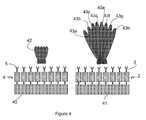
- FIG. 4 shows a block scheme of the system 1 when operating in a second radar mode.
- radar signals are transmitted in a beam 44 having a relatively broad width.
- the processor 8 generates receiving data to a set of angular synthetic receiving aperture beams 43a-h to scan cover a range of angular positions.
- particular receiving data in a specific synthetic receiving aperture beam 43c can be generated by specifically collecting phase information of the received signals from the individual receiving antenna elements 3.
- Figure 5 shows a block scheme of the system 1 when operating in a third radar mode.
- multiple frequency sweep transmission signals are generated, so that, at a particular time instant, the transmitted signal comprises multiple frequency components.
- the individual frequency sweep components are mutually orthogonal.
- the radar resolution improves.
- multiple frequency sweep receiving signals are received.
- the multiple frequency sweep feature is symbolically denoted by a series of transmission beams 45a-h and a series of multiple angular synthetic receiving aperture beams 46a-h.
- FIG. 6 shows a block scheme of the system 1 in a first mode of determining a propagation direction of a received electromagnetic wave, also called electronic warfare support measures (ESM) if the system is applied in the field of military surveillance.
- the linear phased array 4 of transmitting antenna elements is not in operation.
- the linear phased array 2 of receiving antenna elements is in an active state for receiving incoming electromagnetic waves in broad beams 47a-h.
- the processor is arranged for generating, from signals received via the receiving antenna elements 3, receiving data corresponding to a set of respective angular synthetic receiving aperture beams.
- the generation of the receiving data is performed in two steps, a first step corresponding with the first ESM mode.
- the individual receiving antenna elements 3 have each been assigned to corresponding mutually different frequency bands.
- a first receiving antenna element is assigned to a first frequency band
- a second receiving antenna element is assigned to a further, second frequency band, different from the first frequency band, etc. Therefore, a band pass filter can be applied to the received signals.
- the processor 8 determines whether a signal of the receiving antenna elements 3 comprises information of a received electromagnetic wave. If that is the case, an active object transmitting electromagnetic waves has been detected.
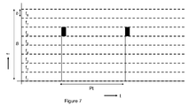
- Figure 7 shows a first frequency diagram wherein any occurrence of signals at a frequency f is set out as a function of time t.
- a total frequency band B is divided in eight subbands f 1 -f 8 , each subband having a subband bandwidth b.
- Each of the eight subbands f 1 -f 8 is assigned to a corresponding receiving antenna element 3.
- a radar pulse signal originating from an external active source is present in the sixth subband f 6 , occurring at pulse repetition times Pt.
- the system is brought in a second ESM mode, shown in Figure 8 .
- the individual receiving antenna elements 3 have been tuned to a specific frequency band that corresponds to the frequency band that has been assigned to the receiving antenna element providing the signal comprising the received electromagnetic wave signal, in the example described above the frequency band f 6 .
- the processor 8 generates, from signals received via the receiving antenna elements 3, receiving data corresponding to a set of respective angular synthetic receiving aperture beams 43a-h. Similar to the strategy as described in relation with a radar mode of the system, the received data can be generated by specifically collecting phase information of the received signals from the individual receiving antenna elements 3. As a result, the direction of the active source emitting radar pulses can be determined.
- a two step approached can be applied, a first step comprising finding frequency information of the pulses and a second step comprising finding angular information of the travelling pulses.
- another strategy can be applied, e.g. operating the system in the second ESM mode while subsequently scanning a multiple number of frequency subbands.
- the second ESM mode can also be applied in searching an active radar source transmitting frequency modulated continuous waveforms.
- Figure 9 shows a second frequency diagram wherein a linear frequency modulated continuous waveform 50 is intercepted at specific time instants t 1 , t 2 , t 3 when the individual receiving antenna elements 3 have been tuned to a specific frequency band f 3 . From the interception data, specific parameters of the frequency modulated continuous waveform 50 can be retrieved, such as a sweep repetition time t sweep .
- Fig. 10 shows a block scheme of the system 1 in a first combined mode wherein the system operates both as a radar and as a system for determining a propagation direction of a received electromagnetic wave.
- a radar signals is transmitted in a beam 60 having a relatively narrow angular width and a specific orientation, wherein a particular receiving antenna element 3a is arranged for receiving a reflected radar signal in relatively broad beam 61.
- the further receiving antenna elements 3b-3h are arranged for determining a propagation direction of a received electromagnetic wave.
- each further antenna element 3b-3h is assigned to corresponding mutually different frequency bands as described referring to Figure 6 .
- the further receiving antenna elements 3b-3h have been tuned to a specific frequency band, so that angular information can be found.
- the system 1 according to the invention can advantageously be used as a relatively compact, light and cheap device on a relatively compact platform. Applications range from surface surveillance, battlefield surveillance, compound security and traffic monitoring to collision avoidance systems.
- processing steps mentioned above can be performed either by dedicated hardware or by standard hardware that is loaded with software suitable for performing the data processing tasks.
- the number of transmitting antenna elements and the number of receiving antenna elements is eight. However, also other numbers of antenna elements can be used. In general, the width of a narrow beam can be reduced if the number of corresponding antenna elements increases, thus improving the angular resolution of the system.
Landscapes
- Engineering & Computer Science (AREA)
- Radar, Positioning & Navigation (AREA)
- Remote Sensing (AREA)
- Physics & Mathematics (AREA)
- General Physics & Mathematics (AREA)
- Computer Networks & Wireless Communication (AREA)
- Radar Systems Or Details Thereof (AREA)
- Variable-Direction Aerials And Aerial Arrays (AREA)
Abstract
The invention relates to a system for determining a propagation direction of a received electromagnetic wave. The system comprises a linear phased array of receiving antenna elements and a processing unit for processing signals received by the receiving antenna elements. The processor is arranged for generating, from the received signals, receiving data corresponding to a set of respective angular synthetic receiving aperture beams.
Description
- The invention relates to a system for determining a propagation direction of a received electromagnetic (EM) wave.
- In the field of localizing EM sources, such as radar transmitting antennas or wireless communications systems, systems are known that are arranged for determining a propagation direction of a propagating electromagnetic wave, e.g. for surface surveillance applications. Such known systems include receiving antenna configurations wherein an antenna element can be pivoted so as to find an optimal receipt angular position indicating an electromagnetic wave propagating direction. Another known system comprises a multiple number of antenna elements that are arranged in a circle, wherein direction information is determined based on amplitude and/or phase differential measurements. Both systems, however, suffer from inaccuracy in determining the propagation direction of a received electromagnetic wave.
- It is an object of the invention to provide a system according to the preamble, wherein the disadvantage identified above is reduced. In particular, the invention aims at obtaining a system according to the preamble that is more accurate. Thereto, according to the invention, the system comprises a linear phased array of receiving antenna elements, and a processing unit for processing signals received by the receiving antenna elements, wherein the processor is arranged for generating, from the received signals, receiving data corresponding to a set of respective angular synthetic receiving aperture beams.
- By receiving signals of a propagating electromagnetic wave by a linear phased array of receiving antenna elements and by generating, from the received signals, receiving data corresponding to a set of respective angular synthetic receiving aperture beams, the feature of a linear phased antenna array of providing a specific angular aperture beam is advantageously exploited. As a result, the measurement sensitivity of each of the multiple number of receiving antenna elements can efficiently be used for receiving electromagnetic waves travelling in a particular propagation direction, thereby improving the overall accuracy of the system. Since the generated receiving data corresponds to a set of respective angular synthetic receiving aperture beams, a range of propagation directions can be scanned by the system.
- In an advantageous embodiment according to the invention, the system comprises a multiple number of linear phased arrays of receiving antenna elements, the phased arrays having a mutually different orientation, thereby enlarging the range of propagation directions that can be scanned by the system. As an example, the linear phased arrays are oriented mutually substantially transversely or along sides of a polygon facing an omnidirectional view.
- In a particular advantageous embodiment according to the invention, the system comprises a linear phased array of transmitting antenna elements for performing, in cooperation with the linear phased array of receiving antenna elements, a radar operation. As a result, the system is able to operate in a radar mode, in a propagation direction finding mode and optionally in a combined mode wherein both a radar operation as well as a propagation direction finding operation is performed. The thus obtained system can be implemented in a compact way while providing various electromagnetic functions, viz. for detecting passive objects by radar and for detecting active objects i.e. objects transmitting electromagnetic fields. By integrating both functions in a single system a system volume and/or weight reduction can be obtained, thus rendering the system flexible and appropriate for use at a relatively small platform.
- The invention also relates to a method of determining a propagation direction of a received electromagnetic wave.
- Further, the invention relates to a computer program product.
- Other advantageous embodiments according to the invention are described in the following claims.
- By way of example only, embodiments of the present invention will now be described with reference to the accompanying figures in which
-
Fig. 1 shows a first block scheme of a first embodiment of a system according to the invention for determining a propagation direction of a received electromagnetic wave; -
Fig. 2 shows a second block scheme of the system shown inFigure 1 ; -
Fig. 3 shows a block scheme of a second embodiment of a system according to the invention for determining a propagation direction of a received electromagnetic wave, in a first radar mode; -
Fig. 4 shows a block scheme of the system ofFigure 3 in a second radar mode; -
Fig. 5 shows a block scheme of the system ofFigure 3 in a third radar mode; -
Fig. 6 shows a block scheme of the system ofFigure 3 in a first electronic warfare support measures (ESM) mode; -
Fig. 7 shows a first frequency diagram; -
Fig. 8 shows a block scheme of the system ofFigure 3 in a second radar mode; -
Fig. 9 shows a second frequency diagram; -
Fig. 10 shows a block scheme of the system ofFigure 3 in a first combined mode; and -
Fig. 11 shows a block scheme of the system ofFigure 3 in a second combined mode. - It is noted that the figures shows merely preferred embodiments according to the invention. In the figures, the same reference numbers refer to equal or corresponding parts.
-
Figure 1 shows a first block scheme of asystem 1 according to the invention for determining a propagation direction D of a received electromagnetic wave W. Thesystem 1 comprises a linearphased array 2 of receivingantenna elements 3 for receiving an incoming electromagnetic field. Further, thesystem 1 comprises a linearphased array 4 of transmittingantenna elements 5 for transmitting a radar field. Eachreceiving antenna element 3 and each transmittingantenna element 5 is connected to aseparate receiver 6 andtransmitter 7, respectively, so that theantenna elements antenna elements 5 is sixteen, while the total number of receivingantenna elements 3 is also sixteen. Further, thesystem 1 comprises aprocessor 8 for processing signals. Also, thesystem 1 comprises a system control unit 9 for controlling thesystem 1, aclock 10 and alocal oscillator 11 for generating a signal to be transmitted and/or to be mixed with a received signal by amixer system 1. -
Figure 2 shows a second block scheme of thesystem 1 described in relation withFig. 1 on a signal level. Here, alocal oscillator signal 20 is conditioned by an amplifier 21 and input to afirst mixer 12a for mixing with a baseband sweep generated by a direct digital synthesizer 21 included in thesystem 1. The directdigital synthesizer 21a is fed by aclock signal 22 and acontrol signal 26 generated by theprocessor 8. Theprocessor 8 is controlled by acontrol signal 25 generated by the system control unit 9. Before mixing the baseband sweep signal, a low pass filtering step is applied by alow pass filter 23a included in thesystem 1. The mixedsignal 24 is fed to anamplifier 27a included in thesystem 1. Then, the amplified signal is transmitting via a transmittingantenna element 5. In a similar way, asimilar transmission signal 28 is generated using a separate path of thesystem 1 including a separate directdigital synthesizer 21b, a separatelow pass filter 23b, aseparate mixer 12b and aseparate amplifier 27b. - Upon receipt of an electromagnetic signal in a
receiving antenna element 7, the signal is conditioned by anamplifier 29, mixed via athird mixer 12c with thetransmission signal 28 generated in the separate processing path of thesystem 1, further conditioned by afurther amplifier 30, aband pass filter 31 and an analog-to-digital converter (ADC) 32 included in thesystem 1. The thus obtained digital signal is further processed by a digital-to-digital converter 33 that is controlled by theprocessor 8. As a result, adigital signal 34 is generated for further processing. - The architecture of the
system 1 is arranged such as to perform a radar operation wherein the transmitted frequency sweep signal is mixed with the received signal to obtain passive object information generating the reflected signal upon incidence of the signal transmitted by thesystem 1. It is noted thatFigures 1 and2 shows a specific component implementation of thesystem 1 according to the invention. Obviously, other or further components can be used. As an example, further spectral filtering can be applied. - The transmitted radar signals have preferably a frequency modulated continuous waveform, more preferably a linear frequency modulated continuous waveform, thereby providing a low probability of intercept radar system that can be implemented in a relatively simple architecture using relatively low cost components. Since the signal reflected by the passive object is received after a delay depending on the distance between the
system 1 and the object, the frequency difference between the transmitted signal and the received signal, also called the beat frequency, at a particular moment is a measure for said distance. The beat frequency is obtained by mixing the receiving signal with the transmitted signal. In principle, also other information can be retrieved from the received signal, such as velocity information of the passive object. This might be accomplished by measuring a Doppler effect. It is further noted that instead of applying a frequency modulated continuous waveform, also other radar signals can be used, such as pulsed signals. -
Figure 3 shows a block scheme of another embodiment of asystem 1 according to the invention, when operating in a first radar mode. Thesystem 1 is now provided with eight transmittingantenna elements 5 and eight receivingantenna elements 3. Thesystem 1 comprises atransmission control unit 40 for controlling operation of the transmittingantenna elements 5. Further, thesystem 1 comprises a receivingcontrol unit 41 for controlling operation of the receivingantenna elements 3. In the first radar mode, the radar signals are transmitted by the linear phasedarray 4 of transmittingantenna elements 5 in abeam 42 having a relatively narrow width. Such abeam 42 can be generated by adjusting the phase of the specific antenna element signals to be transmitted by the linear phasedarray 4. Also the orientation of thenarrow beam 42 can be set by controlling the phase of the individual signals to be transmitted. During operation in said first radar mode, theprocessor 8 generates, from the individual received radar signals, receiving data corresponding to an angular synthetic receivingaperture beam 43 wherein the orientation of the synthetic receiving aperture beam substantially coincides with the orientation of the narrow beam orientation of the transmitted signals, thereby efficiently providing radar information in the narrow beam direction. The received data can be generated by specifically collecting phase information of the received signals from the individual receivingantenna elements 3. By adjusting the orientation of the transmissionnarrow beam 42 and the corresponding synthetic receivingaperture beam 43, a range of angular positions can be scanned. -
Figure 4 shows a block scheme of thesystem 1 when operating in a second radar mode. Here, radar signals are transmitted in a beam 44 having a relatively broad width. Now, theprocessor 8 generates receiving data to a set of angular synthetic receivingaperture beams 43a-h to scan cover a range of angular positions. Again, particular receiving data in a specific synthetic receivingaperture beam 43c can be generated by specifically collecting phase information of the received signals from the individual receivingantenna elements 3. -
Figure 5 shows a block scheme of thesystem 1 when operating in a third radar mode. Here, multiple frequency sweep transmission signals are generated, so that, at a particular time instant, the transmitted signal comprises multiple frequency components. Preferably, the individual frequency sweep components are mutually orthogonal. By using multiple frequency sweep transmission signals the radar resolution improves. At the receivers, similarly, multiple frequency sweep receiving signals are received. InFig. 5 , the multiple frequency sweep feature is symbolically denoted by a series oftransmission beams 45a-h and a series of multiple angular synthetic receivingaperture beams 46a-h. -
Figure 6 shows a block scheme of thesystem 1 in a first mode of determining a propagation direction of a received electromagnetic wave, also called electronic warfare support measures (ESM) if the system is applied in the field of military surveillance. The linear phasedarray 4 of transmitting antenna elements is not in operation. However, the linear phasedarray 2 of receiving antenna elements is in an active state for receiving incoming electromagnetic waves inbroad beams 47a-h. The processor is arranged for generating, from signals received via the receivingantenna elements 3, receiving data corresponding to a set of respective angular synthetic receiving aperture beams. The generation of the receiving data is performed in two steps, a first step corresponding with the first ESM mode. Here, the individual receivingantenna elements 3 have each been assigned to corresponding mutually different frequency bands. As such, a first receiving antenna element is assigned to a first frequency band, a second receiving antenna element is assigned to a further, second frequency band, different from the first frequency band, etc. Therefore, a band pass filter can be applied to the received signals. Then, theprocessor 8 determines whether a signal of the receivingantenna elements 3 comprises information of a received electromagnetic wave. If that is the case, an active object transmitting electromagnetic waves has been detected. -
Figure 7 shows a first frequency diagram wherein any occurrence of signals at a frequency f is set out as a function of time t. A total frequency band B is divided in eight subbands f1-f8, each subband having a subband bandwidth b. Each of the eight subbands f1-f8 is assigned to a correspondingreceiving antenna element 3. InFig. 7 a radar pulse signal originating from an external active source is present in the sixth subband f6, occurring at pulse repetition times Pt. - In order to obtain directional information of the detected active object, the system is brought in a second ESM mode, shown in
Figure 8 . - The individual
receiving antenna elements 3 have been tuned to a specific frequency band that corresponds to the frequency band that has been assigned to the receiving antenna element providing the signal comprising the received electromagnetic wave signal, in the example described above the frequency band f6. Then, theprocessor 8 generates, from signals received via the receivingantenna elements 3, receiving data corresponding to a set of respective angular synthetic receivingaperture beams 43a-h. Similar to the strategy as described in relation with a radar mode of the system, the received data can be generated by specifically collecting phase information of the received signals from the individual receivingantenna elements 3. As a result, the direction of the active source emitting radar pulses can be determined. - Thus, in searching an active radar source transmitting radar pulses, a two step approached can be applied, a first step comprising finding frequency information of the pulses and a second step comprising finding angular information of the travelling pulses. Obviously, also another strategy can be applied, e.g. operating the system in the second ESM mode while subsequently scanning a multiple number of frequency subbands.
- Further, the second ESM mode can also be applied in searching an active radar source transmitting frequency modulated continuous waveforms.
-
Figure 9 shows a second frequency diagram wherein a linear frequency modulatedcontinuous waveform 50 is intercepted at specific time instants t1, t2, t3 when the individual receivingantenna elements 3 have been tuned to a specific frequency band f3. From the interception data, specific parameters of the frequency modulatedcontinuous waveform 50 can be retrieved, such as a sweep repetition time tsweep. -
Fig. 10 shows a block scheme of thesystem 1 in a first combined mode wherein the system operates both as a radar and as a system for determining a propagation direction of a received electromagnetic wave. Here, a radar signals is transmitted in abeam 60 having a relatively narrow angular width and a specific orientation, wherein a particularreceiving antenna element 3a is arranged for receiving a reflected radar signal in relativelybroad beam 61. The further receivingantenna elements 3b-3h are arranged for determining a propagation direction of a received electromagnetic wave. In the first combined mode, eachfurther antenna element 3b-3h is assigned to corresponding mutually different frequency bands as described referring toFigure 6 . In the second combined mode, shown inFig. 11 , the further receivingantenna elements 3b-3h have been tuned to a specific frequency band, so that angular information can be found. - The
system 1 according to the invention can advantageously be used as a relatively compact, light and cheap device on a relatively compact platform. Applications range from surface surveillance, battlefield surveillance, compound security and traffic monitoring to collision avoidance systems. - It is noted that the processing steps mentioned above can be performed either by dedicated hardware or by standard hardware that is loaded with software suitable for performing the data processing tasks.
- The invention is not restricted to the embodiments described herein. It will be understood that many variants are possible.
- In the shown embodiments of
Figures 3-11 , the number of transmitting antenna elements and the number of receiving antenna elements is eight. However, also other numbers of antenna elements can be used. In general, the width of a narrow beam can be reduced if the number of corresponding antenna elements increases, thus improving the angular resolution of the system. - Other such variants will be obvious for the person skilled in the art and are considered to lie within the scope of the invention as formulated in the following claims.
Claims (11)
- A system for determining a propagation direction of a received electromagnetic wave, the system comprising:- a linear phased array of receiving antenna elements, and- a processing unit for processing signals received by the receiving antenna elements,wherein the processor is arranged for generating, from the received signals, receiving data corresponding to a set of respective angular synthetic receiving aperture beams.
- A system according to claim 1, further comprising a multiple number of linear phased arrays of receiving antenna elements, the phase arrays having a mutually different orientation.
- A system according to claim 1 or 2, further comprising a linear phased array of transmitting antenna elements for performing, in cooperation with the linear phased array of receiving antenna elements, a radar operation.
- A method of determining a propagation direction of a received electromagnetic wave, comprising the steps of:- receiving signals of a propagating electromagnetic wave by a linear phased array of receiving antenna elements, and- generating, from the received signals, receiving data corresponding to a set of respective angular synthetic receiving aperture beams.
- A method according to claim 4, comprising the step of tuning the receiving antenna elements to a specific frequency band.
- A method according to claim 5, wherein prior to the step of tuning the receiving antenna elements, the further steps are performed:- assigning a multiple number of receiving antenna elements to corresponding mutually different frequency bands,- determining whether a signal of the multiple number of receiving antenna elements comprises information of a received electromagnetic wave, and- selecting the specific frequency band corresponding with the frequency band assigned to the receiving antenna element providing the signal comprising the received electromagnetic wave signal, as the specific frequency band to which the receiving antenna elements are subsequently tuned.
- A method according to any of the previous claims 4-6, further comprising performing a radar operation by transmitting radar signals via a linear phased array of transmitting antenna elements and by receiving reflected radar signals via the linear phased array of receiving antenna elements.
- A method according to claim 7, comprising transmitting the radar signals in a beam having a relatively narrow width or a relatively broad width and wherein the method further comprises generating, from the received radar signals, receiving data corresponding to an angular synthetic receiving aperture beam or to a set of angular synthetic receiving aperture beams, respectively.
- A method according to any of the previous claim 7 or 8, wherein the transmitted radar signals have a frequency modulated continuous waveform.
- A method according to any of the previous claims 7-9, comprising transmitting the radar signals in a beam having a relatively narrow angular width, wherein a particular receiving antenna element is arranged for receiving a reflected radar signal, and wherein the further receiving antenna elements are arranged for determining a propagation direction of a received electromagnetic wave.
- A computer program product comprising computer readable code for causing a processor to perform a method of determining a propagation direction of a received electromagnetic wave, comprising the step of generating, from signals of a propagating electromagnetic wave received by a linear phased array of receiving antenna elements, receiving data corresponding to a set of respective angular synthetic receiving aperture beams.
Priority Applications (4)
| Application Number | Priority Date | Filing Date | Title |
|---|---|---|---|
| EP08167955A EP2182375A1 (en) | 2008-10-30 | 2008-10-30 | A combined direction finder and radar system, method and computer program product |
| PCT/NL2009/050659 WO2010050816A2 (en) | 2008-10-30 | 2009-10-30 | A system, a method and a computer program product |
| EP09747936A EP2353022A2 (en) | 2008-10-30 | 2009-10-30 | A combined direction finder and radar system, method and computer program product |
| US13/126,995 US9213095B2 (en) | 2008-10-30 | 2009-10-30 | Combined direction finder and radar system, method and computer program product |
Applications Claiming Priority (1)
| Application Number | Priority Date | Filing Date | Title |
|---|---|---|---|
| EP08167955A EP2182375A1 (en) | 2008-10-30 | 2008-10-30 | A combined direction finder and radar system, method and computer program product |
Publications (1)
| Publication Number | Publication Date |
|---|---|
| EP2182375A1 true EP2182375A1 (en) | 2010-05-05 |
Family
ID=40547777
Family Applications (2)
| Application Number | Title | Priority Date | Filing Date |
|---|---|---|---|
| EP08167955A Withdrawn EP2182375A1 (en) | 2008-10-30 | 2008-10-30 | A combined direction finder and radar system, method and computer program product |
| EP09747936A Withdrawn EP2353022A2 (en) | 2008-10-30 | 2009-10-30 | A combined direction finder and radar system, method and computer program product |
Family Applications After (1)
| Application Number | Title | Priority Date | Filing Date |
|---|---|---|---|
| EP09747936A Withdrawn EP2353022A2 (en) | 2008-10-30 | 2009-10-30 | A combined direction finder and radar system, method and computer program product |
Country Status (3)
| Country | Link |
|---|---|
| US (1) | US9213095B2 (en) |
| EP (2) | EP2182375A1 (en) |
| WO (1) | WO2010050816A2 (en) |
Cited By (3)
| Publication number | Priority date | Publication date | Assignee | Title |
|---|---|---|---|---|
| FR3058577A1 (en) * | 2016-11-10 | 2018-05-11 | Thales | RECEIVING DEVICE FOR ELECTRONIC SCAN ANTENNA FOR FUNCTIONING IN RADAR MODE AND RESM, AND RADAR EQUIPPED WITH SUCH A DEVICE |
| CN110018445A (en) * | 2019-03-29 | 2019-07-16 | 南京理工大学 | A kind of active and passive electromagnetic environment cognitive method combined |
| CN112816961A (en) * | 2021-03-17 | 2021-05-18 | 中国人民解放军海军潜艇学院 | Ku wave band phased array water surface target detection system with self-adaptive wave beam stabilization |
Families Citing this family (10)
| Publication number | Priority date | Publication date | Assignee | Title |
|---|---|---|---|---|
| FR2980853B1 (en) * | 2011-09-30 | 2014-11-28 | Thales Sa | DEVICE FOR DETECTING AND LOCATING MOBILE EQUIPPED WITH RADARS AND ASSOCIATED METHOD |
| US9965267B2 (en) * | 2015-11-19 | 2018-05-08 | Raytheon Company | Dynamic interface for firmware updates |
| US10473758B2 (en) | 2016-04-06 | 2019-11-12 | Raytheon Company | Universal coherent technique generator |
| EP3351957B8 (en) * | 2017-01-20 | 2021-12-29 | Rohde & Schwarz GmbH & Co. KG | Method and device for direction finding with direction evaluation |
| BR112020018431B1 (en) * | 2018-08-10 | 2021-08-10 | Lyteloop Technologies, Llc | SYSTEM AND METHOD FOR EXTENDING TRAJECTORY LENGTH OF A WAVE SIGNAL USING ANGLE MULTIPLEXATION |
| US11169240B1 (en) | 2018-11-30 | 2021-11-09 | Ball Aerospace & Technologies Corp. | Systems and methods for determining an angle of arrival of a signal at a planar array antenna |
| US11327142B2 (en) | 2019-03-29 | 2022-05-10 | Ball Aerospace & Technologies Corp. | Systems and methods for locating and tracking radio frequency transmitters |
| CN113791392B (en) * | 2021-08-05 | 2023-11-07 | 中国人民解放军空军工程大学 | A deception method for omnidirectional amplitude-contrast single-pulse direction finding system based on frequency-controlled array |
| CN115575936B (en) * | 2022-09-19 | 2026-03-17 | 北京中星天视科技有限公司 | Location generation methods, apparatus, devices, computer-readable media, and program products |
| CN116774176A (en) * | 2023-05-19 | 2023-09-19 | 中国人民解放军海军航空大学 | ESM and PCL integrated fusion detection system |
Citations (5)
| Publication number | Priority date | Publication date | Assignee | Title |
|---|---|---|---|---|
| US4700191A (en) * | 1985-04-14 | 1987-10-13 | Dan Manor | Radar warning receiver |
| US6377213B1 (en) * | 1998-12-28 | 2002-04-23 | Bushiki Kaisha Toshiba | Wave arrival direction estimating method and antenna apparatus having wave arrival direction estimating function |
| EP1233282A1 (en) * | 2001-02-16 | 2002-08-21 | Thales | System with distributed transmit and receive antennas, in particular for radar with synthetic emission and beamforming |
| US20040061639A1 (en) * | 2000-11-11 | 2004-04-01 | Klaus Voigtlaender | Radar device and method for operating a radar device |
| US20060227050A1 (en) * | 2005-04-07 | 2006-10-12 | Bae Systems Information And Electronic Systems Integration Inc. | Method and apparatus for direction finding |
Family Cites Families (20)
| Publication number | Priority date | Publication date | Assignee | Title |
|---|---|---|---|---|
| BE476540A (en) * | 1946-07-16 | |||
| BE523762A (en) * | 1952-10-27 | |||
| US4301454A (en) | 1979-11-30 | 1981-11-17 | Bunker Ramo Corporation | Channelized receiver system |
| GB2155721B (en) | 1984-03-09 | 1987-09-30 | Decca Ltd | Combined radar and direction finder |
| US4983983A (en) * | 1989-12-05 | 1991-01-08 | The United States Of America As Represented By The Secretary Of The Navy | Semi-automatic direction finding set |
| US5087922A (en) * | 1989-12-08 | 1992-02-11 | Hughes Aircraft Company | Multi-frequency band phased array antenna using coplanar dipole array with multiple feed ports |
| GB2245446A (en) | 1990-06-20 | 1992-01-02 | Philips Electronic Associated | Channelised bearing processor |
| US5613039A (en) * | 1991-01-31 | 1997-03-18 | Ail Systems, Inc. | Apparatus and method for motion detection and tracking of objects in a region for collision avoidance utilizing a real-time adaptive probabilistic neural network |
| US5175559A (en) | 1991-10-24 | 1992-12-29 | Westinghouse Electric Corp. | Combined Radar/ESM antenna system and method |
| US5361072A (en) | 1992-02-28 | 1994-11-01 | Codar Ocean Sensors, Ltd. | Gated FMCW DF radar and signal processing for range/doppler/angle determination |
| US5317319A (en) | 1992-07-17 | 1994-05-31 | Hughes Aircraft Company | Automatic global radar/IR/ESM track association based on ranked candidate pairings and measures of their proximity |
| US5977918A (en) * | 1997-09-25 | 1999-11-02 | The United States Of America As Represented By The Secretary Of The Navy | Extendible planar phased array mast |
| US6104343A (en) * | 1998-01-14 | 2000-08-15 | Raytheon Company | Array antenna having multiple independently steered beams |
| GB9924079D0 (en) * | 1999-10-13 | 2000-05-03 | British Aerospace | Radar systems and methods |
| JP2001264420A (en) | 2000-03-15 | 2001-09-26 | Mitsubishi Electric Corp | Electronic support measures receiving system |
| JP2003066133A (en) | 2001-08-29 | 2003-03-05 | Mitsubishi Electric Corp | Radar equipment |
| US6778137B2 (en) | 2002-03-26 | 2004-08-17 | Raytheon Company | Efficient wideband waveform generation and signal processing design for an active multi-beam ESA digital radar system |
| GB0213976D0 (en) * | 2002-06-18 | 2002-12-18 | Bae Systems Plc | Common aperture antenna |
| GB0517680D0 (en) | 2005-08-31 | 2005-10-05 | Roke Manor Research | Phased array radar |
| US7626538B2 (en) * | 2007-10-24 | 2009-12-01 | Northrop Grumman Systems Corporation | Augmented passive tracking of moving emitter |
-
2008
- 2008-10-30 EP EP08167955A patent/EP2182375A1/en not_active Withdrawn
-
2009
- 2009-10-30 WO PCT/NL2009/050659 patent/WO2010050816A2/en not_active Ceased
- 2009-10-30 US US13/126,995 patent/US9213095B2/en not_active Expired - Fee Related
- 2009-10-30 EP EP09747936A patent/EP2353022A2/en not_active Withdrawn
Patent Citations (5)
| Publication number | Priority date | Publication date | Assignee | Title |
|---|---|---|---|---|
| US4700191A (en) * | 1985-04-14 | 1987-10-13 | Dan Manor | Radar warning receiver |
| US6377213B1 (en) * | 1998-12-28 | 2002-04-23 | Bushiki Kaisha Toshiba | Wave arrival direction estimating method and antenna apparatus having wave arrival direction estimating function |
| US20040061639A1 (en) * | 2000-11-11 | 2004-04-01 | Klaus Voigtlaender | Radar device and method for operating a radar device |
| EP1233282A1 (en) * | 2001-02-16 | 2002-08-21 | Thales | System with distributed transmit and receive antennas, in particular for radar with synthetic emission and beamforming |
| US20060227050A1 (en) * | 2005-04-07 | 2006-10-12 | Bae Systems Information And Electronic Systems Integration Inc. | Method and apparatus for direction finding |
Non-Patent Citations (1)
| Title |
|---|
| LIEVERS C M ET AL: "Digital beam forming on transmit and receive with an AESA FMCW radar", RADAR CONFERENCE, 2007. EURAD 2007. EUROPEAN, IEEE, PI, 1 October 2007 (2007-10-01), pages 47 - 50, XP031191606, ISBN: 978-2-87487-004-0 * |
Cited By (5)
| Publication number | Priority date | Publication date | Assignee | Title |
|---|---|---|---|---|
| FR3058577A1 (en) * | 2016-11-10 | 2018-05-11 | Thales | RECEIVING DEVICE FOR ELECTRONIC SCAN ANTENNA FOR FUNCTIONING IN RADAR MODE AND RESM, AND RADAR EQUIPPED WITH SUCH A DEVICE |
| EP3321711A1 (en) * | 2016-11-10 | 2018-05-16 | Thales | Receiving device for electronic scanning antenna capable of operating in radar and resm mode, and radar provided with such a device |
| US10571549B2 (en) | 2016-11-10 | 2020-02-25 | Thales | Receiving device for an electronically scanned antenna, said device being able to operate in RESM and radar mode, and radar equipped with such a device |
| CN110018445A (en) * | 2019-03-29 | 2019-07-16 | 南京理工大学 | A kind of active and passive electromagnetic environment cognitive method combined |
| CN112816961A (en) * | 2021-03-17 | 2021-05-18 | 中国人民解放军海军潜艇学院 | Ku wave band phased array water surface target detection system with self-adaptive wave beam stabilization |
Also Published As
| Publication number | Publication date |
|---|---|
| US9213095B2 (en) | 2015-12-15 |
| WO2010050816A2 (en) | 2010-05-06 |
| WO2010050816A3 (en) | 2010-10-21 |
| US20110309981A1 (en) | 2011-12-22 |
| EP2353022A2 (en) | 2011-08-10 |
Similar Documents
| Publication | Publication Date | Title |
|---|---|---|
| US9213095B2 (en) | Combined direction finder and radar system, method and computer program product | |
| JP2651054B2 (en) | Polystatic correlation radar | |
| US9470784B2 (en) | Radar device | |
| US7436348B2 (en) | Interferometer-type radar | |
| KR101435168B1 (en) | METHOD AND SYSTEM FOR DETECTING SIGNAL SOURCE IN MONITORING SPACE | |
| EP1872149B1 (en) | Positioning system with a sparse antenna array | |
| US6940447B2 (en) | Radar device and method for operating a radar device | |
| US20080100510A1 (en) | Method and apparatus for microwave and millimeter-wave imaging | |
| US12153125B2 (en) | Radar system and method for performing direction of arrival estimation in a radar system | |
| KR101167906B1 (en) | Radar system for vehicle and method for detecting targets using radar sysem | |
| JPWO2007020704A1 (en) | Target detection method and target detection apparatus | |
| JP6641540B1 (en) | Radar apparatus and signal processing method | |
| KR100979284B1 (en) | Radar transmitter receiver | |
| US20080007449A1 (en) | Radar Sensor | |
| RU2315332C1 (en) | Radiolocation station | |
| KR101634455B1 (en) | Radar using linear frequency modulation signal and noise signal, and method for controlling the same | |
| RU2083996C1 (en) | Method of selection of surface targets | |
| RU2510685C2 (en) | Synthetic-aperture and quasicontinuous radiation radar station | |
| RU2471200C1 (en) | Method for passive detection and spatial localisation of mobile objects | |
| US11960023B2 (en) | Radar device | |
| RU2429501C1 (en) | Detection and direction finding method of air objects | |
| RU2017168C1 (en) | Method for space-based synthetic-aperture radar detection of terrain targets | |
| RU2124221C1 (en) | Radar station | |
| RU2431864C1 (en) | Detection and direction finding method of air objects | |
| JP2001264420A (en) | Electronic support measures receiving system |
Legal Events
| Date | Code | Title | Description |
|---|---|---|---|
| PUAI | Public reference made under article 153(3) epc to a published international application that has entered the european phase |
Free format text: ORIGINAL CODE: 0009012 |
|
| AK | Designated contracting states |
Kind code of ref document: A1 Designated state(s): AT BE BG CH CY CZ DE DK EE ES FI FR GB GR HR HU IE IS IT LI LT LU LV MC MT NL NO PL PT RO SE SI SK TR |
|
| AX | Request for extension of the european patent |
Extension state: AL BA MK RS |
|
| AKY | No designation fees paid | ||
| REG | Reference to a national code |
Ref country code: DE Ref legal event code: 8566 |
|
| STAA | Information on the status of an ep patent application or granted ep patent |
Free format text: STATUS: THE APPLICATION IS DEEMED TO BE WITHDRAWN |
|
| 18D | Application deemed to be withdrawn |
Effective date: 20101106 |