EP2182276A1 - A mounting arrangement for lighting modules and corresponding method - Google Patents
A mounting arrangement for lighting modules and corresponding method Download PDFInfo
- Publication number
- EP2182276A1 EP2182276A1 EP08168026A EP08168026A EP2182276A1 EP 2182276 A1 EP2182276 A1 EP 2182276A1 EP 08168026 A EP08168026 A EP 08168026A EP 08168026 A EP08168026 A EP 08168026A EP 2182276 A1 EP2182276 A1 EP 2182276A1
- Authority
- EP
- European Patent Office
- Prior art keywords
- base plate
- reflector body
- lighting module
- electrical
- formations
- Prior art date
- Legal status (The legal status is an assumption and is not a legal conclusion. Google has not performed a legal analysis and makes no representation as to the accuracy of the status listed.)
- Granted
Links
- 238000000034 method Methods 0.000 title claims description 9
- 230000015572 biosynthetic process Effects 0.000 claims abstract description 23
- 238000005755 formation reaction Methods 0.000 claims abstract description 23
- 230000008878 coupling Effects 0.000 claims abstract description 19
- 238000010168 coupling process Methods 0.000 claims abstract description 19
- 238000005859 coupling reaction Methods 0.000 claims abstract description 19
- 230000000295 complement effect Effects 0.000 claims abstract 6
- 238000006243 chemical reaction Methods 0.000 claims description 5
- PVYBHVJTMRRXLG-UHFFFAOYSA-N 1,2,5-trichloro-3-(3,4-dichlorophenyl)benzene Chemical compound ClC1=CC(Cl)=C(Cl)C(C=2C=C(Cl)C(Cl)=CC=2)=C1 PVYBHVJTMRRXLG-UHFFFAOYSA-N 0.000 description 13
- 239000004020 conductor Substances 0.000 description 4
- 230000000694 effects Effects 0.000 description 2
- 239000000463 material Substances 0.000 description 2
- 239000000853 adhesive Substances 0.000 description 1
- 230000001070 adhesive effect Effects 0.000 description 1
- 238000003491 array Methods 0.000 description 1
- 239000011888 foil Substances 0.000 description 1
- 239000002184 metal Substances 0.000 description 1
- 150000003071 polychlorinated biphenyls Chemical class 0.000 description 1
Images

Classifications
-
- F—MECHANICAL ENGINEERING; LIGHTING; HEATING; WEAPONS; BLASTING
- F21—LIGHTING
- F21V—FUNCTIONAL FEATURES OR DETAILS OF LIGHTING DEVICES OR SYSTEMS THEREOF; STRUCTURAL COMBINATIONS OF LIGHTING DEVICES WITH OTHER ARTICLES, NOT OTHERWISE PROVIDED FOR
- F21V17/00—Fastening of component parts of lighting devices, e.g. shades, globes, refractors, reflectors, filters, screens, grids or protective cages
- F21V17/10—Fastening of component parts of lighting devices, e.g. shades, globes, refractors, reflectors, filters, screens, grids or protective cages characterised by specific fastening means or way of fastening
- F21V17/107—Fastening of component parts of lighting devices, e.g. shades, globes, refractors, reflectors, filters, screens, grids or protective cages characterised by specific fastening means or way of fastening using hinge joints
-
- F—MECHANICAL ENGINEERING; LIGHTING; HEATING; WEAPONS; BLASTING
- F21—LIGHTING
- F21S—NON-PORTABLE LIGHTING DEVICES; SYSTEMS THEREOF; VEHICLE LIGHTING DEVICES SPECIALLY ADAPTED FOR VEHICLE EXTERIORS
- F21S4/00—Lighting devices or systems using a string or strip of light sources
- F21S4/20—Lighting devices or systems using a string or strip of light sources with light sources held by or within elongate supports
-
- F—MECHANICAL ENGINEERING; LIGHTING; HEATING; WEAPONS; BLASTING
- F21—LIGHTING
- F21V—FUNCTIONAL FEATURES OR DETAILS OF LIGHTING DEVICES OR SYSTEMS THEREOF; STRUCTURAL COMBINATIONS OF LIGHTING DEVICES WITH OTHER ARTICLES, NOT OTHERWISE PROVIDED FOR
- F21V17/00—Fastening of component parts of lighting devices, e.g. shades, globes, refractors, reflectors, filters, screens, grids or protective cages
- F21V17/10—Fastening of component parts of lighting devices, e.g. shades, globes, refractors, reflectors, filters, screens, grids or protective cages characterised by specific fastening means or way of fastening
- F21V17/16—Fastening of component parts of lighting devices, e.g. shades, globes, refractors, reflectors, filters, screens, grids or protective cages characterised by specific fastening means or way of fastening by deformation of parts; Snap action mounting
- F21V17/164—Fastening of component parts of lighting devices, e.g. shades, globes, refractors, reflectors, filters, screens, grids or protective cages characterised by specific fastening means or way of fastening by deformation of parts; Snap action mounting the parts being subjected to bending, e.g. snap joints
-
- F—MECHANICAL ENGINEERING; LIGHTING; HEATING; WEAPONS; BLASTING
- F21—LIGHTING
- F21V—FUNCTIONAL FEATURES OR DETAILS OF LIGHTING DEVICES OR SYSTEMS THEREOF; STRUCTURAL COMBINATIONS OF LIGHTING DEVICES WITH OTHER ARTICLES, NOT OTHERWISE PROVIDED FOR
- F21V19/00—Fastening of light sources or lamp holders
- F21V19/001—Fastening of light sources or lamp holders the light sources being semiconductors devices, e.g. LEDs
- F21V19/003—Fastening of light source holders, e.g. of circuit boards or substrates holding light sources
- F21V19/0055—Fastening of light source holders, e.g. of circuit boards or substrates holding light sources by screwing
-
- F—MECHANICAL ENGINEERING; LIGHTING; HEATING; WEAPONS; BLASTING
- F21—LIGHTING
- F21V—FUNCTIONAL FEATURES OR DETAILS OF LIGHTING DEVICES OR SYSTEMS THEREOF; STRUCTURAL COMBINATIONS OF LIGHTING DEVICES WITH OTHER ARTICLES, NOT OTHERWISE PROVIDED FOR
- F21V21/00—Supporting, suspending, or attaching arrangements for lighting devices; Hand grips
- F21V21/002—Supporting, suspending, or attaching arrangements for lighting devices; Hand grips making direct electrical contact, e.g. by piercing
-
- F—MECHANICAL ENGINEERING; LIGHTING; HEATING; WEAPONS; BLASTING
- F21—LIGHTING
- F21V—FUNCTIONAL FEATURES OR DETAILS OF LIGHTING DEVICES OR SYSTEMS THEREOF; STRUCTURAL COMBINATIONS OF LIGHTING DEVICES WITH OTHER ARTICLES, NOT OTHERWISE PROVIDED FOR
- F21V23/00—Arrangement of electric circuit elements in or on lighting devices
- F21V23/001—Arrangement of electric circuit elements in or on lighting devices the elements being electrical wires or cables
-
- F—MECHANICAL ENGINEERING; LIGHTING; HEATING; WEAPONS; BLASTING
- F21—LIGHTING
- F21S—NON-PORTABLE LIGHTING DEVICES; SYSTEMS THEREOF; VEHICLE LIGHTING DEVICES SPECIALLY ADAPTED FOR VEHICLE EXTERIORS
- F21S2/00—Systems of lighting devices, not provided for in main groups F21S4/00 - F21S10/00 or F21S19/00, e.g. of modular construction
- F21S2/005—Systems of lighting devices, not provided for in main groups F21S4/00 - F21S10/00 or F21S19/00, e.g. of modular construction of modular construction
-
- F—MECHANICAL ENGINEERING; LIGHTING; HEATING; WEAPONS; BLASTING
- F21—LIGHTING
- F21V—FUNCTIONAL FEATURES OR DETAILS OF LIGHTING DEVICES OR SYSTEMS THEREOF; STRUCTURAL COMBINATIONS OF LIGHTING DEVICES WITH OTHER ARTICLES, NOT OTHERWISE PROVIDED FOR
- F21V27/00—Cable-stowing arrangements structurally associated with lighting devices, e.g. reels
-
- F—MECHANICAL ENGINEERING; LIGHTING; HEATING; WEAPONS; BLASTING
- F21—LIGHTING
- F21V—FUNCTIONAL FEATURES OR DETAILS OF LIGHTING DEVICES OR SYSTEMS THEREOF; STRUCTURAL COMBINATIONS OF LIGHTING DEVICES WITH OTHER ARTICLES, NOT OTHERWISE PROVIDED FOR
- F21V29/00—Protecting lighting devices from thermal damage; Cooling or heating arrangements specially adapted for lighting devices or systems
- F21V29/50—Cooling arrangements
- F21V29/70—Cooling arrangements characterised by passive heat-dissipating elements, e.g. heat-sinks
-
- F—MECHANICAL ENGINEERING; LIGHTING; HEATING; WEAPONS; BLASTING
- F21—LIGHTING
- F21Y—INDEXING SCHEME ASSOCIATED WITH SUBCLASSES F21K, F21L, F21S and F21V, RELATING TO THE FORM OR THE KIND OF THE LIGHT SOURCES OR OF THE COLOUR OF THE LIGHT EMITTED
- F21Y2115/00—Light-generating elements of semiconductor light sources
- F21Y2115/10—Light-emitting diodes [LED]
Definitions
- a basic problem left unsolved by conventional arrangements as described in the foregoing is reducing the time devoted to realize multiple modules especially as regards reducing the time spent for the electrical connection of an array of high power LED modules, while also ensuring an easy handling pattern of light sources.
- An embodiment of the arrangement described herein thus provides a simple and fast coupling connection process for LED modules while ensuring electrical connection and thermal dissipation as required.
- each module 10 may in turn include one or more LED lighting sources such as a high-power LED lighting sources L (see figure 4 ).
- each module 10 may include an array of say, two to four LED sources L.
- the PCB 107 carries the LED sources L at its upper side (i.e. the side “internal” to the body 106 - see figure 4 ) and is provided at its lower side (i.e. the side "external” to the body 106 - see figure 2 ) with contact pins 108 to contact the conductors 1040 in the strip 104.
- these formations are in the form of arch-like leaf-springs extending between the LED sources.
- these formations can be simply comprised of thin wall portions of the reflector body 106 extending between the openings for the light sources L provided in the "bottom" portion 1060.
- the electrical line 104 is then extended (e.g. unwound) to connect said the base plates 102 already mounted on the mounting surface 100.
- the reflector bodies 106 of the modules 10, carrying the PCBs 107 with the LED sources are then mounted on the base plates 102 by snap-like coupling the reflector bodies 106 with the respective base plates 102 with the electrical line 104 interposed therebetween.
- the electrical line 104 is adhesively connected to the mounting surface 100.
Landscapes
- Engineering & Computer Science (AREA)
- General Engineering & Computer Science (AREA)
- Fastening Of Light Sources Or Lamp Holders (AREA)
- Arrangement Of Elements, Cooling, Sealing, Or The Like Of Lighting Devices (AREA)
- Non-Portable Lighting Devices Or Systems Thereof (AREA)
Abstract
Description
- This disclosure relates to mounting arrangements for lighting modules.
- This disclosure was devised with specific attention paid to its possible application to mounting arrangements for arrays of high power LED modules.
- When using conventional arrangements, realizing a circuit including an array of LED modules requires connecting multiple LED modules by means of cables and fasteners, which essentially involves a sequential procedure. Creating a pattern of LED modules thus requires locating every single module in place and then establishing electrical connections by cabling the modules one after the other. In the case of an array including, say, a number of modules equal to n, this involves n base plate placement operations, followed by n (if parallel) or n - 1 (if series) electrical connection operations, and then n reflector placement operations.
- A basic problem left unsolved by conventional arrangements as described in the foregoing is reducing the time devoted to realize multiple modules especially as regards reducing the time spent for the electrical connection of an array of high power LED modules, while also ensuring an easy handling pattern of light sources.
- The object of the invention is to provide a solution to that problem.
- According to the present invention, such an object is achieved by means of an arrangement having the features set forth in the claims that follow.
- The invention also relates to a corresponding method.
- The claims are an integral part of the disclosure of the invention provided herein.
- An embodiment of the arrangement described herein thus provides a simple and fast coupling connection process for LED modules while ensuring electrical connection and thermal dissipation as required.
- An embodiment of the arrangement described herein is adapted to provide electrical connection in a single operation.
- An embodiment of the arrangement described herein is adapted to provide "smart" replacement and good handling features.
- The invention will now be described, by way of example only, with reference to the enclosed representations, wherein:
-
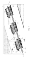
Figure 1 is a general schematic view of an arrangement as described herein with certain parts omitted/shown in phantom lines; -
Figures 2 and 3 are perspective views of certain parts of the embodiment illustrated infigure 1 ; and -
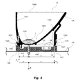
Figure 4 is a cross-sectional view along line IV-IV offigure 1 . - In the following description, numerous specific details are given to provide a thorough understanding of embodiments. The embodiments can be practiced without one or more of the specific details, or with other methods, components, materials, etc. In other instances, well-known structures, materials, or operations are not shown or described in detail to avoid obscuring aspects of the embodiments.
- Reference throughout this specification to "one embodiment" or "an embodiment" means that a particular feature, structure, or characteristic described in connection with the embodiment is included in at least one embodiment. Thus, the appearances of the phrases "in one embodiment" or "in an embodiment" in various places throughout this specification are not necessarily all referring to the same embodiment. Furthermore, the particular features, structures, or characteristics may be combined in any suitable manner in one or more embodiments.
- The headings provided herein are for convenience only and do not interpret the scope or meaning of the embodiments.
- The embodiment illustrated in the figures aims at reducing the cost of the process and the number of components involved in producing a lighting source including a plurality of
LED lighting modules 10. Eachmodule 10 may in turn include one or more LED lighting sources such as a high-power LED lighting sources L (seefigure 4 ). In an embodiment, eachmodule 10 may include an array of say, two to four LED sources L. - The modules 10 (e.g. three of these
modules 10, with reference tofigure 1 ) are mounted on a common support surface (of any type: e.g. a lamp structure) 100. - Each module 10 (hereinafter, the
modules 10 will be considered to be identical, so that only one of these will be described in detail) is mounted on thesurface 100 via a (e.g. metallic - i.e. heat dissipative)base plate 102 in the form of a shaped body fixed to thesurface 100. Fixing may be viascrews 102a as shown or by any other means. - In an embodiment, the
base plate 102 has a channel-like shape overall, including: - a
flat web portion 1020 to lie flat against thesurface 100, and - two
side portions 1022 to extend upwardly from thesurface 100. Theside portions 1022 haveholes 1024, 1025 (or similar formations) for snap-in engagement of parts of themodule 10 to be described in the following. - Electrical connection of the
various modules 10 is provided via aconnector 104 in the form of e.g. a flexible ("flex") adhesive strip carrying e.g. twoconductors 1040. As schematically shown infigure 1 (top right), such astrip 104 can be unwound and extended across a plurality ofbase plates 102 to rapidly provide stable electrical connection of the corresponding modules. This while also ensuring that all themodules 10 arranged on thesurface 100 are connected with the same phase: this is ensured by the strip being flat, so that the electrical conductors therein maintain their mutual position provided the strip is not twisted. - Both
figure 1 and the cross sectional view offigure 4 show thestrip 104 interposed between thebase plate 102 and thebody 106 of the module 10 (thebody 106 of only one of the modules is illustrated in shadow lines infigure 1 ). - In the embodiment illustrated, the
strip 104 is in fact interposed between thebase plate 102 and a (e.g. metal core i.e. heat-dissipative) printed circuit board or PCB 107 carried by thebody 106. - The
PCB 107 carries the LED sources L at its upper side (i.e. the side "internal" to the body 106 - seefigure 4 ) and is provided at its lower side (i.e. the side "external" to the body 106 - seefigure 2 ) withcontact pins 108 to contact theconductors 1040 in thestrip 104. - In the embodiment illustrated, two pairs of
contact pins 108 are provided for the LED sources L arranged in thebody 106. In the embodiment illustrated, thecontact pins 108 are in the form of spring-loaded pins adapted to contact theconductors 1040 by being pushed thereby against/into thePCB 107 that are mounted provided for two LED sources L arranged in thebody 106. - Thermal coupling of the
PCB 107 and thebase plate 102 is increased by the mechanical action of thebody 106, which also acts as a reflector, as better detailed in the following (e.g. by means of leaf springs that urge thePCB 107 against thebase plate 102, possibly squeezing a TIM foil therebetween). - In the embodiment illustrated, the LED sources L and the
pins 108 are carried by thePCB 107 at opposite sides thereof. - As best appreciated in the sectional view of
figure 4 , thebody 106 is generally vat-shaped with abottom portion 1060 provided with apertures for the LED sources L mounted on thePCB 107 andrespective lenses 1062 associated therewith. - Further details of the mounting arrangement of the LED sources L and the
lenses 1062 as well as thePCB 107 on thereflector body 106 can be found in a parallel application filed on even date by the same applicant. - The
inner surface 1064 of thereflector body 106 is treated to be reflective (by known means, e.g. by being provided with reflective facets) and shaped (e.g. by having an at least approximately parabolic or paraboloid-like shape) to properly direct the light rays from the LED sources L (and especially the "outer" fraction of these light rays possibly escaping the focusing action of the lenses 1062) towards the distal opening 1066 of thereflector body 106 to be projected from themodule 10. - Connection of the
reflector body 106 with thebase plate 102 is by snap-like engagement. To that effect, in the embodiment shown thereflector body 106 carries tooth formations adapted to engage theholes side portions 1022 of thebase plate 102. - In the exemplary embodiment as illustrated, these tooth formations include a set of e.g. three
teeth 1068 adapted to engage threecorresponding holes 1024 in theside portion 1022 of thebase plate 102 which is proximate to the LED sources. - Engagement of the
teeth 1068 in theholes 1024 creates a sort of hinge-like coupling between thereflector body 106 and thebase plate 102. Thereflector body 106 can thus be rotated in a clamp-like fashion against thebase plate 102 until atooth 1070 provided at the opposite side of thereflector body 106 engages in a snap-like fashion acorresponding hole 1025 in theside portion 1022 of thebase plate 102 which is proximate to thestrip 104. - As a result of this snap-like engagement, the
reflector body 106 is securely fixed the base plate 102 (and thus to the surface 100), with thestrip 104 likewise securely clamped between thePCB 107 and thebase plate 102 to provide electrical connection to the LED or LEDs in themodule 10. - In the exemplary embodiment illustrated one or more spring-
like formations 1072 are interposed between thereflector body 106 and the PCB 107 to urge the PCB 107 against thebase plate 102 and provide good thermal coupling therebetween. - In the exemplary embodiment illustrated, these formations are in the form of arch-like leaf-springs extending between the LED sources. In an embodiment, these formations can be simply comprised of thin wall portions of the
reflector body 106 extending between the openings for the light sources L provided in the "bottom"portion 1060. - The
formations 1072 create a force system as shown infigure 4 , by creating a force F1 which urges thePCB 107 towards thebase plate 102 and corresponding reaction forces F2 and F3 acting on theside portions 1020 of thebase plate 102. Specifically force F2 acts between the "locking"tooth 1070 and thecorresponding opening 1025, while force F3 acts between the "hinge"teeth 1068 and thecorresponding openings 1024. - Due to the lever effect thus created, this arrangement may produce a relevant force on the
leaf springs 1072 even in the presence of a moderate reaction force at the "locking"tooth 1070. In fact:

where a and b denote the distance of the point of action of theleaf springs 1072 to theteeth 1068 and thetooth 1070, respectively. - In fact, as the ratio "b/a" increases (i.e. as the
leaf springs 1072 are arranged increasingly closer to theteeth 1068 than to the tooth 1070), the reaction force is increasingly supported by therear teeth 1068, which explains why plural teeth may be used to distribute this reaction force. - Experiments carried out by the applicant indicate that good thermal coupling is achieved if the
PCB 107 is urged against thebase plate 102 with a force of 20N. - In an exemplary case: a=14mm, b=37mm


- In an embodiment, an array of
lighting modules 10 as described herein can be mounted on a mountingsurface 100 by first mounting on that surface thebase plates 102 of the modules. - The
electrical line 104 is then extended (e.g. unwound) to connect said thebase plates 102 already mounted on the mountingsurface 100. Thereflector bodies 106 of themodules 10, carrying thePCBs 107 with the LED sources are then mounted on thebase plates 102 by snap-like coupling thereflector bodies 106 with therespective base plates 102 with theelectrical line 104 interposed therebetween. - In an embodiment, the
electrical line 104 is adhesively connected to the mountingsurface 100. - Without prejudice to the underlying principles of the invention, the details and the embodiments may vary, even appreciably, with reference to what has been described by way of example only, without departing from the scope of the invention as defined by the annexed claims.
Claims (14)
- A lighting module (10) including:- a base plate (102) for fixing to a mounting surface (100),- a reflector body (106) carrying a printed circuit board (107) with at least one electrical light source (L), wherein said printed circuit board (107) includes electrical contact pins (108) to said at least one electrical light source (L),- said base plate (102) and said reflector body (106) having complementary coupling formations (1024, 1068; 1025, 1070) for snap-like coupling said base plate (102) and said reflector body (106) with an electrical line (104) interposed therebetween for feeding said at least one electrical light source (L) with said electrical contact pins (108) electrically contacting said electrical line (104).
- The lighting module (10) of Claim 1, including at least one force-generating formation (1072) to urge said printed circuit board (107) against said base plate (102).
- The lighting module (10) of either of Claims 1 or 2, wherein said complementary coupling formations (1024, 1068; 1025, 1070) include:- at least one set of hinge-like coupling formations (1024, 1068) to establish a clamp-like coupling between said base plate (102) and said reflector body (106), thereby permitting rotation of said reflector body (106) against said base plate (102), and- a set of locking formations (1025, 1070) to lock to said base plate (102) said reflector body (106) rotated against said base plate (102).
- The lighting module (10) of Claims 2 and 3, wherein said at least one force-generating formation (1072) is arranged at a distance (a) to said set of hinge-like coupling formations (1024; 1068) smaller than the distance (b) to said set of locking formations (1024, 1070).
- The lighting module (10) of Claim 4, including a plurality of sets of hinge-like coupling formations (1024, 1068) to provide a reaction force (F3) to the force produced by said force-generating formations (1072).
- The lighting module (10) of any of the preceding, wherein said base plate (102) includes:- a flat web portion (1020), and- two side portions (1022) extending channel-like from said web portion (1020), wherein said side portion (1022) include at least part of said complementary coupling formations (1024, 1025) with said reflector body (106).
- The lighting module (10) of Claim 6, wherein said side portions (1022) include openings (1024, 1025) comprising a part of said complementary coupling formations (1024, 1025) with said reflector body (106).
- The lighting module (10) of any of the previous, wherein said reflector body (106) is provided with teeth (1068, 1070) comprising at least part of said complementary coupling formations (1024) with said base plate (102).
- The lighting module of Claim 2, wherein said reflector body (106) includes at least one arch-like leaf-spring element (1072) to provide said at least one force-generating formation.
- The lighting module of any of the previous claims, wherein said at least one electrical light source (L) is a LED.
- The lighting module of any of the previous claims, the module having said electrical line (104) interposed between said base plate (102() and said reflector body (106), said electrical line in the form of a flexible strip (104).
- The lighting module of any of the previous claims, the module having said electrical line (104) interposed between said base plate (102() and said reflector body (106), said electrical line (104) adhesively connected to said mounting surface (100).
- A method of mounting on a mounting surface (100) an array of lighting modules (10), the method including:- providing a plurality of lighting modules (10) according to any of claims 1 to 10,- mounting on said mounting surface (100) the base plates (102) of said plurality of lighting modules (10),- extending said electrical line (104) to connect said base plates (102) of said plurality of lighting modules (10) mounted on said mounting surface (100), and- mounting on said base plates (102) of said plurality of lighting modules (10) mounted on said mounting surface (100) the reflector bodies (106) of said plurality of lighting modules (10), said reflector bodies (106) carrying each a printed circuit board (107) with at least one electrical light source (L),wherein said mounting the reflector bodies (106) includes snap-like coupling said reflector bodies (106) with respective base plates (102) with said electrical line (104) interposed therebetween.
- The method of Claim 13, including adhesively connecting said electrical line (104) to said mounting surface (100).
Priority Applications (5)
| Application Number | Priority Date | Filing Date | Title |
|---|---|---|---|
| EP08168026A EP2182276B1 (en) | 2008-10-31 | 2008-10-31 | A mounting arrangement for lighting modules and corresponding method |
| US12/609,024 US8602595B2 (en) | 2008-10-31 | 2009-10-30 | Mounting arrangement for lighting modules and corresponding method |
| CN200910211386.XA CN101725856B (en) | 2008-10-31 | 2009-10-30 | Installation arrangement of light-emitting module and corresponding method |
| PCT/EP2009/064397 WO2010049529A1 (en) | 2008-10-31 | 2009-10-30 | A mounting arrangement for light sources and corresponding method |
| PCT/EP2009/064355 WO2010049517A1 (en) | 2008-10-31 | 2009-10-30 | A mounting arrangement for light sources and corresponding method |
Applications Claiming Priority (1)
| Application Number | Priority Date | Filing Date | Title |
|---|---|---|---|
| EP08168026A EP2182276B1 (en) | 2008-10-31 | 2008-10-31 | A mounting arrangement for lighting modules and corresponding method |
Publications (3)
| Publication Number | Publication Date |
|---|---|
| EP2182276A1 true EP2182276A1 (en) | 2010-05-05 |
| EP2182276A8 EP2182276A8 (en) | 2010-07-07 |
| EP2182276B1 EP2182276B1 (en) | 2012-04-11 |
Family
ID=40184992
Family Applications (1)
| Application Number | Title | Priority Date | Filing Date |
|---|---|---|---|
| EP08168026A Not-in-force EP2182276B1 (en) | 2008-10-31 | 2008-10-31 | A mounting arrangement for lighting modules and corresponding method |
Country Status (3)
| Country | Link |
|---|---|
| US (1) | US8602595B2 (en) |
| EP (1) | EP2182276B1 (en) |
| CN (1) | CN101725856B (en) |
Cited By (1)
| Publication number | Priority date | Publication date | Assignee | Title |
|---|---|---|---|---|
| CN107481974A (en) * | 2017-07-14 | 2017-12-15 | 岳西县吉奥电子器件有限公司 | A kind of integrated circuit be easy to pick and place and installed |
Families Citing this family (11)
| Publication number | Priority date | Publication date | Assignee | Title |
|---|---|---|---|---|
| US8308320B2 (en) * | 2009-11-12 | 2012-11-13 | Cooper Technologies Company | Light emitting diode modules with male/female features for end-to-end coupling |
| US8764220B2 (en) | 2010-04-28 | 2014-07-01 | Cooper Technologies Company | Linear LED light module |
| WO2011139764A2 (en) | 2010-04-27 | 2011-11-10 | Cooper Technologies Company | Linkable linear light emitting diode system |
| US8240887B2 (en) * | 2010-08-27 | 2012-08-14 | Tyco Electronics Corporation | LED light module |
| US9765945B2 (en) | 2012-03-07 | 2017-09-19 | Osram Gmbh | Lighting device |
| DE102013203916A1 (en) * | 2013-03-07 | 2014-09-11 | Zumtobel Lighting Gmbh | Luminaire with a LED light module |
| DE102013114627A1 (en) * | 2013-12-20 | 2015-06-25 | Alanod Gmbh & Co. Kg | Luminaire reflector for LED lights |
| US9772092B2 (en) * | 2014-11-14 | 2017-09-26 | Hella Kgaa Hueck & Co. | Lamp assembly and method for torque-free assembly of the lamp assembly |
| DE102016102279A1 (en) * | 2015-07-15 | 2017-01-19 | Heraeus Noblelight Gmbh | Module-like LED emitter unit and use of the same |
| US9861003B2 (en) * | 2016-04-21 | 2018-01-02 | US LED, Ltd. | Mounting clip |
| GB2639234A (en) * | 2024-03-12 | 2025-09-17 | Collingwood Lighting Ltd | Luminaire and method for manufacturing a luminaire |
Citations (5)
| Publication number | Priority date | Publication date | Assignee | Title |
|---|---|---|---|---|
| US5944463A (en) * | 1997-07-22 | 1999-08-31 | Savage, Jr.; John M. | Clamp connection of electrical wiring and electrical lead structure |
| DE10306720A1 (en) * | 2003-02-18 | 2004-08-26 | Triebold, Klaus-Jörg | Illumination and signal lighting unit for pedestrians and sport and leisure activities has lighting elements that can be changed are inserted into small carrier plates and are provided in different luminosity and color |
| EP1586810A2 (en) * | 2004-04-16 | 2005-10-19 | VLM S.p.A. | Modular lighting system including high-powered LED lighting modules |
| US20070217192A1 (en) * | 2005-08-30 | 2007-09-20 | Toshio Hiratsuka | Illuminating Panel and Illuminating Device |
| DE102006048230A1 (en) * | 2006-10-11 | 2008-04-17 | Patent-Treuhand-Gesellschaft für elektrische Glühlampen mbH | Light-emitting diode system, method for producing such and backlighting device |
Family Cites Families (10)
| Publication number | Priority date | Publication date | Assignee | Title |
|---|---|---|---|---|
| US5442529A (en) * | 1994-04-04 | 1995-08-15 | Hoover; Richard P. | Combination knife, light and key chain device |
| US6641284B2 (en) | 2002-02-21 | 2003-11-04 | Whelen Engineering Company, Inc. | LED light assembly |
| US20050152133A1 (en) * | 2004-01-13 | 2005-07-14 | Chang Kao | Integrated greeting message and lighted jewelry box |
| US7210957B2 (en) * | 2004-04-06 | 2007-05-01 | Lumination Llc | Flexible high-power LED lighting system |
| US7330106B2 (en) * | 2004-04-27 | 2008-02-12 | Paulson Cindy L | Severe and controlled braking alert signaling apparatus for vehicles |
| TWI294986B (en) * | 2004-10-08 | 2008-03-21 | Premier Image Technology Corp | An optical engine and an image projector having the optical engine |
| US7810955B2 (en) * | 2007-07-19 | 2010-10-12 | Lumination Llc | Linear LED illumination system |
| CN101255980A (en) | 2007-09-13 | 2008-09-03 | 孙敬玺 | Heat pipe radiator and high-power LED road lamp |
| US7736174B2 (en) * | 2007-12-04 | 2010-06-15 | Pass & Seymour, Inc. | Illuminated face receptacle structure |
| US20110075413A1 (en) * | 2009-09-30 | 2011-03-31 | Smith Gregory S | Lighting system |
-
2008
- 2008-10-31 EP EP08168026A patent/EP2182276B1/en not_active Not-in-force
-
2009
- 2009-10-30 CN CN200910211386.XA patent/CN101725856B/en not_active Expired - Fee Related
- 2009-10-30 US US12/609,024 patent/US8602595B2/en not_active Expired - Fee Related
Patent Citations (5)
| Publication number | Priority date | Publication date | Assignee | Title |
|---|---|---|---|---|
| US5944463A (en) * | 1997-07-22 | 1999-08-31 | Savage, Jr.; John M. | Clamp connection of electrical wiring and electrical lead structure |
| DE10306720A1 (en) * | 2003-02-18 | 2004-08-26 | Triebold, Klaus-Jörg | Illumination and signal lighting unit for pedestrians and sport and leisure activities has lighting elements that can be changed are inserted into small carrier plates and are provided in different luminosity and color |
| EP1586810A2 (en) * | 2004-04-16 | 2005-10-19 | VLM S.p.A. | Modular lighting system including high-powered LED lighting modules |
| US20070217192A1 (en) * | 2005-08-30 | 2007-09-20 | Toshio Hiratsuka | Illuminating Panel and Illuminating Device |
| DE102006048230A1 (en) * | 2006-10-11 | 2008-04-17 | Patent-Treuhand-Gesellschaft für elektrische Glühlampen mbH | Light-emitting diode system, method for producing such and backlighting device |
Cited By (1)
| Publication number | Priority date | Publication date | Assignee | Title |
|---|---|---|---|---|
| CN107481974A (en) * | 2017-07-14 | 2017-12-15 | 岳西县吉奥电子器件有限公司 | A kind of integrated circuit be easy to pick and place and installed |
Also Published As
| Publication number | Publication date |
|---|---|
| CN101725856A (en) | 2010-06-09 |
| CN101725856B (en) | 2014-04-23 |
| EP2182276A8 (en) | 2010-07-07 |
| US8602595B2 (en) | 2013-12-10 |
| EP2182276B1 (en) | 2012-04-11 |
| US20100110680A1 (en) | 2010-05-06 |
Similar Documents
| Publication | Publication Date | Title |
|---|---|---|
| EP2182276B1 (en) | A mounting arrangement for lighting modules and corresponding method | |
| EP1048965B1 (en) | Optical connector module | |
| EP0936400B1 (en) | Multiple light emitting diode module | |
| US6494749B1 (en) | Connector with mounting fixture for removable storage device | |
| US7134883B2 (en) | Connecting box for connecting to a solar panel | |
| US6422716B2 (en) | Modular led assembly | |
| EP2471145B1 (en) | Board-to-board connector system | |
| US20140233227A1 (en) | Holder element for holding at least one flat surface-light lamp, set of a plurality of lampholders and a plurality of elongate holding bodies and luminaire | |
| CN101806420A (en) | Lighting unit and harness equipped with the lighting unit | |
| US6910903B2 (en) | Receptacle mounting bracket attached to frame | |
| US7724540B1 (en) | Spacer for circuit boards | |
| CN217983834U (en) | Modular connector | |
| JP2010529641A (en) | Apparatus and method for connecting multiple photovoltaic modules | |
| US11167631B2 (en) | Assembly of electric accumulators | |
| EP2716968B1 (en) | Lighting device | |
| US9151454B1 (en) | Modular LED lighting apparatus | |
| US20130322078A1 (en) | Low-cost multi functional heatsink for LED arrays | |
| TWI759831B (en) | Pcb interconnect scheme for co-planar led strips | |
| CN217982070U (en) | Modular connector | |
| CN113258324B (en) | Light source connection module and connector thereof | |
| JPH02226187A (en) | Display module and multiple unit display built up therewith | |
| JP2005175137A (en) | Terminal structure of flexible board | |
| CN102176558A (en) | LRM (Line replaceable module) low-frequency high-density surface mount connector plug | |
| TW202331147A (en) | Module connector | |
| US20230246376A1 (en) | Module connector |
Legal Events
| Date | Code | Title | Description |
|---|---|---|---|
| PUAI | Public reference made under article 153(3) epc to a published international application that has entered the european phase |
Free format text: ORIGINAL CODE: 0009012 |
|
| AK | Designated contracting states |
Kind code of ref document: A1 Designated state(s): AT BE BG CH CY CZ DE DK EE ES FI FR GB GR HR HU IE IS IT LI LT LU LV MC MT NL NO PL PT RO SE SI SK TR |
|
| AX | Request for extension of the european patent |
Extension state: AL BA MK RS |
|
| RAP1 | Party data changed (applicant data changed or rights of an application transferred) |
Owner name: OSRAM GESELLSCHAFT MIT BESCHRAENKTER HAFTUNG Owner name: OSRAM S.P.A. - SOCIETA' RIUNITE OSRAM EDISON CLERI |
|
| 17P | Request for examination filed |
Effective date: 20100913 |
|
| AKX | Designation fees paid |
Designated state(s): DE FR GB IT |
|
| RAP1 | Party data changed (applicant data changed or rights of an application transferred) |
Owner name: OSRAM S.P.A. - SOCIETA' RIUNITE OSRAM EDISON CLERI Owner name: OSRAM AG |
|
| GRAP | Despatch of communication of intention to grant a patent |
Free format text: ORIGINAL CODE: EPIDOSNIGR1 |
|
| GRAS | Grant fee paid |
Free format text: ORIGINAL CODE: EPIDOSNIGR3 |
|
| GRAA | (expected) grant |
Free format text: ORIGINAL CODE: 0009210 |
|
| AK | Designated contracting states |
Kind code of ref document: B1 Designated state(s): DE FR GB IT |
|
| REG | Reference to a national code |
Ref country code: GB Ref legal event code: FG4D |
|
| REG | Reference to a national code |
Ref country code: DE Ref legal event code: R096 Ref document number: 602008014764 Country of ref document: DE Effective date: 20120606 |
|
| REG | Reference to a national code |
Ref country code: DE Ref legal event code: R097 Ref document number: 602008014764 Country of ref document: DE |
|
| PLBE | No opposition filed within time limit |
Free format text: ORIGINAL CODE: 0009261 |
|
| STAA | Information on the status of an ep patent application or granted ep patent |
Free format text: STATUS: NO OPPOSITION FILED WITHIN TIME LIMIT |
|
| RAP2 | Party data changed (patent owner data changed or rights of a patent transferred) |
Owner name: OSRAM GMBH Owner name: OSRAM S.P.A. - SOCIETA' RIUNITE OSRAM EDISON CLERI |
|
| 26N | No opposition filed |
Effective date: 20130114 |
|
| REG | Reference to a national code |
Ref country code: DE Ref legal event code: R081 Ref document number: 602008014764 Country of ref document: DE Owner name: OSRAM GMBH, DE Free format text: FORMER OWNER: OSRAM AG, 81543 MUENCHEN, DE Effective date: 20130205 |
|
| REG | Reference to a national code |
Ref country code: DE Ref legal event code: R097 Ref document number: 602008014764 Country of ref document: DE Effective date: 20130114 |
|
| REG | Reference to a national code |
Ref country code: DE Ref legal event code: R081 Ref document number: 602008014764 Country of ref document: DE Owner name: OSRAM GMBH, DE Free format text: FORMER OWNER: OSRAM GMBH, 81543 MUENCHEN, DE Effective date: 20130823 |
|
| REG | Reference to a national code |
Ref country code: FR Ref legal event code: PLFP Year of fee payment: 8 |
|
| PGFP | Annual fee paid to national office [announced via postgrant information from national office to epo] |
Ref country code: GB Payment date: 20151021 Year of fee payment: 8 Ref country code: IT Payment date: 20151028 Year of fee payment: 8 |
|
| PGFP | Annual fee paid to national office [announced via postgrant information from national office to epo] |
Ref country code: FR Payment date: 20151023 Year of fee payment: 8 |
|
| PGFP | Annual fee paid to national office [announced via postgrant information from national office to epo] |
Ref country code: DE Payment date: 20161020 Year of fee payment: 9 |
|
| GBPC | Gb: european patent ceased through non-payment of renewal fee |
Effective date: 20161031 |
|
| REG | Reference to a national code |
Ref country code: FR Ref legal event code: ST Effective date: 20170630 |
|
| PG25 | Lapsed in a contracting state [announced via postgrant information from national office to epo] |
Ref country code: GB Free format text: LAPSE BECAUSE OF NON-PAYMENT OF DUE FEES Effective date: 20161031 Ref country code: FR Free format text: LAPSE BECAUSE OF NON-PAYMENT OF DUE FEES Effective date: 20161102 |
|
| PG25 | Lapsed in a contracting state [announced via postgrant information from national office to epo] |
Ref country code: IT Free format text: LAPSE BECAUSE OF NON-PAYMENT OF DUE FEES Effective date: 20161031 |
|
| REG | Reference to a national code |
Ref country code: DE Ref legal event code: R119 Ref document number: 602008014764 Country of ref document: DE |
|
| PG25 | Lapsed in a contracting state [announced via postgrant information from national office to epo] |
Ref country code: DE Free format text: LAPSE BECAUSE OF NON-PAYMENT OF DUE FEES Effective date: 20180501 |