EP2182201A1 - Foundation particularly for a wind turbine and wind turbine - Google Patents
Foundation particularly for a wind turbine and wind turbine Download PDFInfo
- Publication number
- EP2182201A1 EP2182201A1 EP08019186A EP08019186A EP2182201A1 EP 2182201 A1 EP2182201 A1 EP 2182201A1 EP 08019186 A EP08019186 A EP 08019186A EP 08019186 A EP08019186 A EP 08019186A EP 2182201 A1 EP2182201 A1 EP 2182201A1
- Authority
- EP
- European Patent Office
- Prior art keywords
- foundation
- segments
- wind turbine
- central
- bottom plate
- Prior art date
- Legal status (The legal status is an assumption and is not a legal conclusion. Google has not performed a legal analysis and makes no representation as to the accuracy of the status listed.)
- Granted
Links
- 239000004567 concrete Substances 0.000 claims description 18
- 239000011440 grout Substances 0.000 claims description 6
- 239000004570 mortar (masonry) Substances 0.000 claims description 6
- 238000004873 anchoring Methods 0.000 claims description 5
- 238000010276 construction Methods 0.000 description 10
- 229910000831 Steel Inorganic materials 0.000 description 5
- 238000004519 manufacturing process Methods 0.000 description 5
- 239000010959 steel Substances 0.000 description 5
- 238000011065 in-situ storage Methods 0.000 description 4
- 238000009434 installation Methods 0.000 description 4
- 238000000034 method Methods 0.000 description 4
- 238000005266 casting Methods 0.000 description 2
- 230000001419 dependent effect Effects 0.000 description 1
- 238000011161 development Methods 0.000 description 1
- 230000018109 developmental process Effects 0.000 description 1
- 230000000694 effects Effects 0.000 description 1
- 238000005516 engineering process Methods 0.000 description 1
- 230000005484 gravity Effects 0.000 description 1
- 238000005304 joining Methods 0.000 description 1
- 239000000463 material Substances 0.000 description 1
- 238000003908 quality control method Methods 0.000 description 1
- VWDWKYIASSYTQR-UHFFFAOYSA-N sodium nitrate Chemical group [Na+].[O-][N+]([O-])=O VWDWKYIASSYTQR-UHFFFAOYSA-N 0.000 description 1
- 230000007704 transition Effects 0.000 description 1
Images

Classifications
-
- F—MECHANICAL ENGINEERING; LIGHTING; HEATING; WEAPONS; BLASTING
- F03—MACHINES OR ENGINES FOR LIQUIDS; WIND, SPRING, OR WEIGHT MOTORS; PRODUCING MECHANICAL POWER OR A REACTIVE PROPULSIVE THRUST, NOT OTHERWISE PROVIDED FOR
- F03D—WIND MOTORS
- F03D13/00—Assembly, mounting or commissioning of wind motors; Arrangements specially adapted for transporting wind motor components
- F03D13/20—Arrangements for mounting or supporting wind motors; Masts or towers for wind motors
- F03D13/22—Foundations specially adapted for wind motors
-
- E—FIXED CONSTRUCTIONS
- E02—HYDRAULIC ENGINEERING; FOUNDATIONS; SOIL SHIFTING
- E02D—FOUNDATIONS; EXCAVATIONS; EMBANKMENTS; UNDERGROUND OR UNDERWATER STRUCTURES
- E02D27/00—Foundations as substructures
- E02D27/32—Foundations for special purposes
- E02D27/42—Foundations for poles, masts or chimneys
- E02D27/425—Foundations for poles, masts or chimneys specially adapted for wind motors masts
-
- F—MECHANICAL ENGINEERING; LIGHTING; HEATING; WEAPONS; BLASTING
- F05—INDEXING SCHEMES RELATING TO ENGINES OR PUMPS IN VARIOUS SUBCLASSES OF CLASSES F01-F04
- F05B—INDEXING SCHEME RELATING TO WIND, SPRING, WEIGHT, INERTIA OR LIKE MOTORS, TO MACHINES OR ENGINES FOR LIQUIDS COVERED BY SUBCLASSES F03B, F03D AND F03G
- F05B2240/00—Components
- F05B2240/90—Mounting on supporting structures or systems
-
- Y—GENERAL TAGGING OF NEW TECHNOLOGICAL DEVELOPMENTS; GENERAL TAGGING OF CROSS-SECTIONAL TECHNOLOGIES SPANNING OVER SEVERAL SECTIONS OF THE IPC; TECHNICAL SUBJECTS COVERED BY FORMER USPC CROSS-REFERENCE ART COLLECTIONS [XRACs] AND DIGESTS
- Y02—TECHNOLOGIES OR APPLICATIONS FOR MITIGATION OR ADAPTATION AGAINST CLIMATE CHANGE
- Y02E—REDUCTION OF GREENHOUSE GAS [GHG] EMISSIONS, RELATED TO ENERGY GENERATION, TRANSMISSION OR DISTRIBUTION
- Y02E10/00—Energy generation through renewable energy sources
- Y02E10/70—Wind energy
- Y02E10/72—Wind turbines with rotation axis in wind direction
-
- Y—GENERAL TAGGING OF NEW TECHNOLOGICAL DEVELOPMENTS; GENERAL TAGGING OF CROSS-SECTIONAL TECHNOLOGIES SPANNING OVER SEVERAL SECTIONS OF THE IPC; TECHNICAL SUBJECTS COVERED BY FORMER USPC CROSS-REFERENCE ART COLLECTIONS [XRACs] AND DIGESTS
- Y02—TECHNOLOGIES OR APPLICATIONS FOR MITIGATION OR ADAPTATION AGAINST CLIMATE CHANGE
- Y02E—REDUCTION OF GREENHOUSE GAS [GHG] EMISSIONS, RELATED TO ENERGY GENERATION, TRANSMISSION OR DISTRIBUTION
- Y02E10/00—Energy generation through renewable energy sources
- Y02E10/70—Wind energy
- Y02E10/728—Onshore wind turbines
-
- Y—GENERAL TAGGING OF NEW TECHNOLOGICAL DEVELOPMENTS; GENERAL TAGGING OF CROSS-SECTIONAL TECHNOLOGIES SPANNING OVER SEVERAL SECTIONS OF THE IPC; TECHNICAL SUBJECTS COVERED BY FORMER USPC CROSS-REFERENCE ART COLLECTIONS [XRACs] AND DIGESTS
- Y02—TECHNOLOGIES OR APPLICATIONS FOR MITIGATION OR ADAPTATION AGAINST CLIMATE CHANGE
- Y02P—CLIMATE CHANGE MITIGATION TECHNOLOGIES IN THE PRODUCTION OR PROCESSING OF GOODS
- Y02P70/00—Climate change mitigation technologies in the production process for final industrial or consumer products
- Y02P70/50—Manufacturing or production processes characterised by the final manufactured product
-
- Y—GENERAL TAGGING OF NEW TECHNOLOGICAL DEVELOPMENTS; GENERAL TAGGING OF CROSS-SECTIONAL TECHNOLOGIES SPANNING OVER SEVERAL SECTIONS OF THE IPC; TECHNICAL SUBJECTS COVERED BY FORMER USPC CROSS-REFERENCE ART COLLECTIONS [XRACs] AND DIGESTS
- Y10—TECHNICAL SUBJECTS COVERED BY FORMER USPC
- Y10T—TECHNICAL SUBJECTS COVERED BY FORMER US CLASSIFICATION
- Y10T403/00—Joints and connections
- Y10T403/45—Flexibly connected rigid members
- Y10T403/459—Helical spring type coupling
Definitions
- the invention relates to a foundation particularly a foundation of a wind turbine and to a wind turbine.
- Wind turbines are installations with a very tall tower which typically carries a rotor, housing and an electric generator of the wind turbine on its top. Since the used towers are very large in height in order to enable the use of a rotor with a large radius or length of the rotor blades the wind turbines are very heavy. Additionally the wind turbines are of course typically installed in topographic areas in which a strong wind is quite common and therefore the construction of the wind turbines have to be that strong to withstand the forces acting on such turbines due to the strong wind with typically high wind speed.
- EP 1058787 B1 discloses a foundation which is assembled of essentially uniformly formed base piece segments which are made of steel and which are arranged such that the assembled piece segments create a circular steel foundation with a hole at the center of the circle.
- On-shore foundations are usually created at the location of the wind turbine installation using standard concrete casting technology to cast the foundation in situ.
- EP 1058787 B1 discloses an off-shore foundation which is not used on-shore.
- the first object of the invention will be solved by a foundation according to the features of claim 1, the second object by a wind turbine as claimed in claim 9.
- the depending claims contain further developments of the invention.
- An inventive foundation particularly a foundation of a wind turbine comprises a central foundation member and a plurality of foundation segments which are segments of a circular, ring shaped or polygonal foundation element and which are connected to the central foundation member by means of one or more locking elements.
- the foundation may, in particular, be realised as a shallow foundation.
- the locking elements may, e.g., be a ring shaped or polygonal projection of or a ring shaped or polygonal recess in the central foundation member together with recesses or projections of the foundation segments, respectively.
- the recesses or projections of the foundation segments can then engage the projection or recess in the central foundation member.
- the plurality of foundation segments or the foundation segments and the foundation member are joined together by means of a fixation means surrounding the segments or which is incorporated by the segments.
- the fixation means may, in particular, be a strap surrounding the segments, e.g., a steel band.
- the foundation segments and the foundation member are joined together by means of concrete, grout or mortar.
- This allows a better connection between the segments and the member and reduces relative movement of the segments and the member respectively. Since the amount of used concrete, grout or mortar is quite low compared to the material which has to be used for an in situ cast process this process is much faster in production than the in situ process of casting the whole foundation.
- the foundation member is or comprises a bottom plate. Both the foundation segments and the bottom plate comprise rebars where the rebars of the foundation segments and the bottom plate overlap when the foundation segments and the bottom plate are in place at the location of the foundation. The foundation segments with the rebars and the bottom plate with the rebars are joined together by means of concrete, grout or mortar.
- the foundation segments and the bottom plate are joined together by means of concrete. After hardening the joining concrete can form the foundation member together with the bottom plate.
- the foundation member may be not fully pre-fabricated but partly cast at the construction site while the segments are preferably pre-manufactured.
- the foundation segments may comprise anchoring elements for anchoring a wind turbine tower.
- the foundation segments may comprise support elements for such anchoring elements instead anchoring elements itself.
- An inventive wind turbine comprises an inventive foundation and a tower anchored at the foundation.
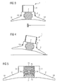
- Figure 1 show a foundation 1 according to a first embodiment of the invention especially for wind turbines in a perspective view.
- the foundation 1 contains a plurality of foundation segments 2, which are arranged to build a circular or polygonal foundation.
- Each segment 2 comprises a shoulder 3 which protrudes towards the center of the foundation, i.e. towards the wind turbine, and at which fastening means 4 are provided to be used to fasten an element 5 of the wind turbine tower to the foundation 1.
- the fastening means 4 are preferably bolts or anchors, especially stud bolts, to be able to fasten an element 5 of a tower of a wind turbine to the foundation 1. Since the bolts or stud bolts are integrally connected to the segments 2 of the foundation they allow the fastening of the circular element 5 of the tower to the circular or polygonal shaped foundation by means of nuts and screws. However, instead of providing the fastening means 4 itself at the shoulder 3 it is also possible to only provide supports for which bay be part of the tower element 5 of individual elements which are niter part of the foundation segments 2 nor of the tower element 5.
- Fig. 2 shows a sectional view of the foundation 1 shown in Fig. 1 .
- the sectional view allows seeing the side face 6 of the segments 2 and the central foundation member 7 in a first embodiment.
- the central foundation member 7 has a central portion 8 and lateral portions 9, 10.
- the central portion 8 has a larger diameter or radius than the two lateral portions 9, 10.
- the central foundation member has a hole 11 which is aligned in axial direction of the central foundation member 7.
- the segments 2 are such that they comprise a recess 12 at the radial inner face of the shoulder 3. Therefore the side face 6 shows the recess 12.
- extended portion 8 of the central foundation member 7 is located within the recess 12 of the segments 2. This allows a tight and stable connection between the segments 2 and the central foundation member 7. In other words, the central portion 8 and the recesses 12 serve as locking members to prevent tilting of the foundation segments 2 relative to the central foundation member 7.
- Fig. 2 shows that the fastening means 4 are located at the upper side face of the shoulder 3 of the segments 2.
- Fig. 1 and fig. 2 the segments are arranged in a circular or polygonal arrangement creating a closed circle or polygonal structure. Therefore the shape of a segment looks like a piece of cake if seen from above the foundation.
- the foundation 1 is an assembly of a plurality of segments and a central foundation member which are connected and fastened to build a single piece of foundation at the construction site.
- the creation and manufacturing of the segments at a different production site than at the construction site of the wind turbine allows the manufacturing at a less whether dependent site which may cause a higher concrete quality, a better control of the manufacturing process, a better quality control of the product and the process and a shorter construction time at the construction site, which is appreciated since this may lead to reduced costs.
- Fig. 3 and Fig. 4 show a foundation in a sectional view the foundation contains the segments 2 and the central foundation member 7 which are clamped together and to the central foundation member 7. Additionally it is of advantage that the segments 2 are forced together by the strap 13 which surrounds the segments e.g. at a central position e.g. at the transition point between the shoulder 3 and the radial extending wings 14 of the segments.
- the central foundation member 7 can be cast at the construction site while the segments 2 are pre-manufactured and pre-assembled before filling out the central space within the hole of the segments 2 arrangement.
- the central foundation member 7 may comprise a pre-manufactured bottom plate 71 around which the foundation segments 2 will be arranged at the construction side.
- the bottom plate 71 centers the segments 2 at their bottom ends.
- a tool 72 like e.g. a steel plate, may be used to center the segments 2 at their top ends.
- Both the bottom plate 71 and the foundation segments 2 are equipped with rebars73, 74.
- the rebars 74 of the segments 2 are located at their radial inner ends and project over the rebars 73 of the bottom plate 71 when the foundation segments 2 are in place.
- a top layer of rebars 75 may be arranged on top of the rebars 74 of the foundation segments 2 after removing the tool 72 and before filling the space between the segments 2 with concrete.
- the rebars 73, 74, 75 provide for good monolithic structure of the foundation 1 after the concrete is hardened. In other words, the rebars 73, 74, 75 and the hardened concrete serve as locking members to prevent tilting of the foundation segments 2 relative to the central foundation member.
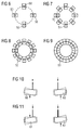
- Figures 6 to 9 show different solutions to arrange a plurality of foundations of a tower of a wind turbine.
- Figure 6 shows an arrangement of four rectangular foundations 50 which are arranged like a cross.
- Figure 7 shows an arrangement of eight rectangular foundations 51 which are arranged like two crosses which are arranged with a respective angle of 45°. Such an arrangement comes already close to a circle.
- Figure 8 shows an arrangement of twelve rectangular foundations 52 which are arranged like three crosses which are arranged with a respective angle of 30°. Such an arrangement is already almost like a circle.
- Last but not least Figure 9 shows an arrangement of twenty foundation segments 53 having the shape like a pieces of cake and which are arranged such that they create a circle or a ring as continuous shell.
- Figures 10 and 11 both show an effect of a tilting of foundations 60, 61 like two foundations of Figure 6 .
- both foundations 60 are tilted anti-parallel. This means that the tilting angle with respect to the normal axis has the same size but an opposite algebraic sign.
- both foundations 61 are tilted in the same direction. This means that the tilting angle with respect to the normal axis has the same size and the same algebraic sign.
- foundations have to be fixed with respect to the other foundations or foundation segments.
Abstract
Description
- The invention relates to a foundation particularly a foundation of a wind turbine and to a wind turbine.
- Wind turbines are installations with a very tall tower which typically carries a rotor, housing and an electric generator of the wind turbine on its top. Since the used towers are very large in height in order to enable the use of a rotor with a large radius or length of the rotor blades the wind turbines are very heavy. Additionally the wind turbines are of course typically installed in topographic areas in which a strong wind is quite common and therefore the construction of the wind turbines have to be that strong to withstand the forces acting on such turbines due to the strong wind with typically high wind speed.
- Therefore strong foundations are necessary requirements of the construction of such wind turbines.
- Such foundations are well known in the art. The article BONUS Wind Turbines, Foundations, Foundation, Bonus Wind turbines , rev. 3 pages 1 to 4, 21.03.02 discloses a gravity foundation with a concrete base plate with a central concrete plinth. Furthermore it discloses piled foundations with pre-fabricated piles which will be hammered to the necessary depth into the ground and foundations with piles which will be cast in situ.
- The prior art document
EP 1058787 B1 discloses a foundation which is assembled of essentially uniformly formed base piece segments which are made of steel and which are arranged such that the assembled piece segments create a circular steel foundation with a hole at the center of the circle. - On-shore foundations are usually created at the location of the wind turbine installation using standard concrete casting technology to cast the foundation in situ. The above mentioned document
EP 1058787 B1 discloses an off-shore foundation which is not used on-shore. - The above mentioned foundations show the disadvantage that the concrete foundations are difficult to produce at the location of the wind turbine installation and that the steel foundation is not well suited for heavy on-shore wind turbine installations.
- It is a first object of the invention to create a foundation particularly for a wind turbine which can be produced more easily and which saves time at the location of the construction site of the wind turbine and which can be produced with higher quality.
- It is a second object of the invention to provide a wind turbine wit an advantageous foundation.
- The first object of the invention will be solved by a foundation according to the features of claim 1, the second object by a wind turbine as claimed in claim 9. The depending claims contain further developments of the invention.
- An inventive foundation particularly a foundation of a wind turbine comprises a central foundation member and a plurality of foundation segments which are segments of a circular, ring shaped or polygonal foundation element and which are connected to the central foundation member by means of one or more locking elements. The foundation may, in particular, be realised as a shallow foundation.
- The locking elements may, e.g., be a ring shaped or polygonal projection of or a ring shaped or polygonal recess in the central foundation member together with recesses or projections of the foundation segments, respectively. The recesses or projections of the foundation segments can then engage the projection or recess in the central foundation member.
- According to an embodiment of the invention the plurality of foundation segments or the foundation segments and the foundation member are joined together by means of a fixation means surrounding the segments or which is incorporated by the segments. The fixation means may, in particular, be a strap surrounding the segments, e.g., a steel band. An advantage might be to put the strap around the segments at the position of a circumferentially extending shoulder of the plurality of the segments.
- With regard to another embodiment of the invention the foundation segments and the foundation member are joined together by means of concrete, grout or mortar. This allows a better connection between the segments and the member and reduces relative movement of the segments and the member respectively. Since the amount of used concrete, grout or mortar is quite low compared to the material which has to be used for an in situ cast process this process is much faster in production than the in situ process of casting the whole foundation. In a practical realisation, the foundation member is or comprises a bottom plate. Both the foundation segments and the bottom plate comprise rebars where the rebars of the foundation segments and the bottom plate overlap when the foundation segments and the bottom plate are in place at the location of the foundation. The foundation segments with the rebars and the bottom plate with the rebars are joined together by means of concrete, grout or mortar.
- Furthermore it is of advantage that the foundation segments and the bottom plate are joined together by means of concrete. After hardening the joining concrete can form the foundation member together with the bottom plate. In other words, the foundation member may be not fully pre-fabricated but partly cast at the construction site while the segments are preferably pre-manufactured.
- In the inventive foundation the foundation segments may comprise anchoring elements for anchoring a wind turbine tower. Alternatively, the foundation segments may comprise support elements for such anchoring elements instead anchoring elements itself.
- An inventive wind turbine comprises an inventive foundation and a tower anchored at the foundation.
- The above and other features and advantages of the invention will be apparent from the following description of an exemplary embodiment of the invention with reference to the accompanying drawings, in which:
-
Fig. 1 shows a perspective view of a first embodiment of the inventive foundation; -
Fig. 2 shows a perspective sectional view of the first embodiment; -
Fig. 3 shows a schematic sectional view of the first embodiment; -
Fig. 4 shows a schematic sectional view of the first embodiment; -
Fig. 5 shows a schematic sectional view of a second embodiment of the inventive foundation; -
Fig. 6 shows an arrangement of foundations or foundation segments; -
Fig. 7 shows a further arrangement of foundations or foundation segments; -
Fig. 8 shows a still further arrangement of foundations or foundation segments; -
Fig. 9 shows a still further arrangement of foundations or foundation segments; -
Fig. 10 shows a tilting of foundations or foundation segments; and -
Fig. 11 shows a tilting of foundations or foundation segments. -
Figure 1 show a foundation 1 according to a first embodiment of the invention especially for wind turbines in a perspective view.. The foundation 1 contains a plurality offoundation segments 2, which are arranged to build a circular or polygonal foundation. Eachsegment 2 comprises ashoulder 3 which protrudes towards the center of the foundation, i.e. towards the wind turbine, and at which fastening means 4 are provided to be used to fasten anelement 5 of the wind turbine tower to the foundation 1. - The fastening means 4 are preferably bolts or anchors, especially stud bolts, to be able to fasten an
element 5 of a tower of a wind turbine to the foundation 1. Since the bolts or stud bolts are integrally connected to thesegments 2 of the foundation they allow the fastening of thecircular element 5 of the tower to the circular or polygonal shaped foundation by means of nuts and screws. However, instead of providing the fastening means 4 itself at theshoulder 3 it is also possible to only provide supports for which bay be part of thetower element 5 of individual elements which are niter part of thefoundation segments 2 nor of thetower element 5. -
Fig. 2 shows a sectional view of the foundation 1 shown inFig. 1 . The sectional view allows seeing theside face 6 of thesegments 2 and thecentral foundation member 7 in a first embodiment. - The
central foundation member 7 has acentral portion 8 andlateral portions 9, 10. Thecentral portion 8 has a larger diameter or radius than the twolateral portions 9, 10. Furthermore the central foundation member has ahole 11 which is aligned in axial direction of thecentral foundation member 7. - The
segments 2 are such that they comprise arecess 12 at the radial inner face of theshoulder 3. Therefore theside face 6 shows therecess 12. As can be seen onFig. 2 extended portion 8 of thecentral foundation member 7 is located within therecess 12 of thesegments 2. This allows a tight and stable connection between thesegments 2 and thecentral foundation member 7. In other words, thecentral portion 8 and therecesses 12 serve as locking members to prevent tilting of thefoundation segments 2 relative to thecentral foundation member 7. - In order to allow a tight fit between the
segments 2 and thecentral foundation member 7 an additional concrete, grout or mortar filling may appreciated. This allows filling out even small slits or grooves between them. AdditionallyFig. 2 shows that the fastening means 4 are located at the upper side face of theshoulder 3 of thesegments 2. - As can be seen from
Fig. 1 and fig. 2 the segments are arranged in a circular or polygonal arrangement creating a closed circle or polygonal structure. Therefore the shape of a segment looks like a piece of cake if seen from above the foundation. - The foundation 1 is an assembly of a plurality of segments and a central foundation member which are connected and fastened to build a single piece of foundation at the construction site. The creation and manufacturing of the segments at a different production site than at the construction site of the wind turbine allows the manufacturing at a less whether dependent site which may cause a higher concrete quality, a better control of the manufacturing process, a better quality control of the product and the process and a shorter construction time at the construction site, which is appreciated since this may lead to reduced costs.
-
Fig. 3 and Fig. 4 show a foundation in a sectional view the foundation contains thesegments 2 and thecentral foundation member 7 which are clamped together and to thecentral foundation member 7. Additionally it is of advantage that thesegments 2 are forced together by thestrap 13 which surrounds the segments e.g. at a central position e.g. at the transition point between theshoulder 3 and theradial extending wings 14 of the segments. - This allows acting against a tilting of
single segments 2 such that the whole foundation has to be tilted and this is a more stable solution. - According to another embodiment of the invention the
central foundation member 7 can be cast at the construction site while thesegments 2 are pre-manufactured and pre-assembled before filling out the central space within the hole of thesegments 2 arrangement. Such an embodiment is schematically shown inFig. 5 . In this embodiment, thecentral foundation member 7 may comprise apre-manufactured bottom plate 71 around which thefoundation segments 2 will be arranged at the construction side. Thebottom plate 71 centers thesegments 2 at their bottom ends. Atool 72, like e.g. a steel plate, may be used to center thesegments 2 at their top ends. - Both the
bottom plate 71 and thefoundation segments 2 are equipped with rebars73, 74. Therebars 74 of thesegments 2 are located at their radial inner ends and project over therebars 73 of thebottom plate 71 when thefoundation segments 2 are in place. A top layer ofrebars 75 may be arranged on top of therebars 74 of thefoundation segments 2 after removing thetool 72 and before filling the space between thesegments 2 with concrete. Therebars rebars foundation segments 2 relative to the central foundation member. -
Figures 6 to 9 show different solutions to arrange a plurality of foundations of a tower of a wind turbine.Figure 6 shows an arrangement of fourrectangular foundations 50 which are arranged like a cross.Figure 7 shows an arrangement of eightrectangular foundations 51 which are arranged like two crosses which are arranged with a respective angle of 45°. Such an arrangement comes already close to a circle.Figure 8 shows an arrangement of twelverectangular foundations 52 which are arranged like three crosses which are arranged with a respective angle of 30°. Such an arrangement is already almost like a circle. Last but not leastFigure 9 shows an arrangement of twentyfoundation segments 53 having the shape like a pieces of cake and which are arranged such that they create a circle or a ring as continuous shell. -
Figures 10 and 11 both show an effect of a tilting offoundations Figure 6 . InFig. 10 bothfoundations 60 are tilted anti-parallel. This means that the tilting angle with respect to the normal axis has the same size but an opposite algebraic sign. InFig. 11 bothfoundations 61 are tilted in the same direction. This means that the tilting angle with respect to the normal axis has the same size and the same algebraic sign. - This means that the foundations have to be fixed with respect to the other foundations or foundation segments. This might be done according to the first embodiment by using a fully pre-manufactured central foundation member and foundation segments forced together by the strap or according to the second embodiment by using a bottom plate, rebars and concrete which connects the bottom plate to segments and forms together with the bottom plate a central foundation member after the concrete is hardened.
Claims (9)
- A foundation (1), particularly a foundation of a wind turbine, comprising a central foundation member (7) and a plurality of foundation segments (2) which are segments of a circular, ring shaped or polygonal foundation element and which are connected to the central foundation member (7) by means of one or more locking elements.
- The foundation (1) as claimed in claim 1, wherein the locking elements are a ring shaped or polygonal projection of or a ring shaped or polygonal recess in the central foundation member (7) and recesses or projections of the foundation segments (2), respectively, which can engage the projection or recess in the central foundation member (7).
- The foundation (1) as claimed in claim 1, wherein the foundation segments (2) and the foundation member (7) are joined together by means of a fixation means (13) surrounding the segments or which is incorporated by the segments.
- The foundation (1) as claimed in claim 3, wherein the fixation means is a strap (13) surrounding the segments.
- The foundation (1) as claimed in any of the claims 1 to 4, wherein the foundation segments (2) and the foundation member (7) are joined together by means of concrete, grout or mortar.
- The foundation (1) as claimed in claim 5, wherein- the foundation member (7) is or comprises a bottom plate (71);- the foundation segments (2) and the bottom plate (71) comprise rebars (73, 74) where the rebars (74) of the foundation segments (2) and the rebars (73) of the bottom plate (71) overlap when the foundation segments (2) and the bottom plate (71) are in place;- the foundation segments (2) and the bottom plate (71) with the rebars (73, 74) are joined together by means of concrete, grout or mortar.
- The foundation (1) as claimed in any of the claims 1 to 6, wherein the foundation segments (2) comprises anchoring elements (4) for a wind turbine tower (5).
- The foundation (1) as claimed in any of the claims 1 to 7, wherein the foundation (1) is a shallow foundation.
- A wind turbine with a foundation (1) as claimed in any of the claims 1 to 8 and a tower (5) anchored at the foundation (1).
Priority Applications (11)
| Application Number | Priority Date | Filing Date | Title |
|---|---|---|---|
| DK10168320.9T DK2256338T3 (en) | 2008-11-03 | 2008-11-03 | Foundation, especially for a wind turbine and wind turbine |
| ES10168320.9T ES2448769T3 (en) | 2008-11-03 | 2008-11-03 | Foundation, particularly for a wind turbine, and wind turbine |
| EP10168320.9A EP2256338B1 (en) | 2008-11-03 | 2008-11-03 | Foundation particularly for a wind turbine and wind turbine |
| DK08019186.9T DK2182201T3 (en) | 2008-11-03 | 2008-11-03 | Foundation, especially for a windmill, and windmill |
| EP08019186.9A EP2182201B1 (en) | 2008-11-03 | 2008-11-03 | Foundation particularly for a wind turbine and wind turbine |
| US12/608,187 US8359798B2 (en) | 2008-11-03 | 2009-10-29 | Foundation particularly for a wind turbine and wind turbine |
| JP2009249662A JP5431116B2 (en) | 2008-11-03 | 2009-10-30 | Especially for windmill foundations and windmills |
| CA2684184A CA2684184A1 (en) | 2008-11-03 | 2009-10-30 | Foundation particularly for a wind turbine and wind turbine |
| NZ587247A NZ587247A (en) | 2008-11-03 | 2009-11-02 | A segmented wind turbine foundation connected to a pre-formed base plate by poured concrete and rebar |
| NZ580892A NZ580892A (en) | 2008-11-03 | 2009-11-02 | Foundation using a central member with a keyway or projection mating with a plurality of foundation segments |
| CN200910174941.6A CN101725483B (en) | 2008-11-03 | 2009-11-03 | Foundation particularly for a wind turbine and wind turbine |
Applications Claiming Priority (1)
| Application Number | Priority Date | Filing Date | Title |
|---|---|---|---|
| EP08019186.9A EP2182201B1 (en) | 2008-11-03 | 2008-11-03 | Foundation particularly for a wind turbine and wind turbine |
Related Child Applications (1)
| Application Number | Title | Priority Date | Filing Date |
|---|---|---|---|
| EP10168320.9A Division-Into EP2256338B1 (en) | 2008-11-03 | 2008-11-03 | Foundation particularly for a wind turbine and wind turbine |
Publications (2)
| Publication Number | Publication Date |
|---|---|
| EP2182201A1 true EP2182201A1 (en) | 2010-05-05 |
| EP2182201B1 EP2182201B1 (en) | 2016-01-13 |
Family
ID=41099187
Family Applications (2)
| Application Number | Title | Priority Date | Filing Date |
|---|---|---|---|
| EP08019186.9A Active EP2182201B1 (en) | 2008-11-03 | 2008-11-03 | Foundation particularly for a wind turbine and wind turbine |
| EP10168320.9A Active EP2256338B1 (en) | 2008-11-03 | 2008-11-03 | Foundation particularly for a wind turbine and wind turbine |
Family Applications After (1)
| Application Number | Title | Priority Date | Filing Date |
|---|---|---|---|
| EP10168320.9A Active EP2256338B1 (en) | 2008-11-03 | 2008-11-03 | Foundation particularly for a wind turbine and wind turbine |
Country Status (8)
| Country | Link |
|---|---|
| US (1) | US8359798B2 (en) |
| EP (2) | EP2182201B1 (en) |
| JP (1) | JP5431116B2 (en) |
| CN (1) | CN101725483B (en) |
| CA (1) | CA2684184A1 (en) |
| DK (2) | DK2182201T3 (en) |
| ES (1) | ES2448769T3 (en) |
| NZ (2) | NZ587247A (en) |
Cited By (9)
| Publication number | Priority date | Publication date | Assignee | Title |
|---|---|---|---|---|
| DE102018112857A1 (en) | 2017-12-13 | 2019-06-13 | Universelle-Fertigteil-Fundamente GmbH | Foundation for a wind turbine |
| DE102019109503A1 (en) | 2018-04-16 | 2019-10-17 | Universelle-Fertigteil-Fundamente GmbH | Foundation for a wind turbine |
| DE202020105643U1 (en) | 2020-09-29 | 2022-01-04 | Anker Foundations GmbH | Foundation for a wind turbine |
| DE202020106971U1 (en) | 2020-10-04 | 2022-01-07 | Anker Foundations GmbH | Foundation for a wind turbine |
| DE202021105272U1 (en) | 2020-09-29 | 2022-03-25 | Anker Werk I Port Mukran Gmbh | Anchor cage for a foundation for a wind turbine |
| DE102021125328A1 (en) | 2020-09-29 | 2022-03-31 | Anker Foundations GmbH | Anchor cage for a foundation for a wind turbine |
| DE102020125441A1 (en) | 2020-09-29 | 2022-03-31 | Anker Foundations GmbH | Foundation for a wind turbine |
| DE102020125918A1 (en) | 2020-10-04 | 2022-04-07 | Anker Foundations GmbH | Foundation for a wind turbine |
| DE102021122183A1 (en) | 2021-08-26 | 2023-03-02 | Smart & Green Mukran Concrete Gmbh | Foundation for a tower for a wind turbine |
Families Citing this family (43)
| Publication number | Priority date | Publication date | Assignee | Title |
|---|---|---|---|---|
| DE102009051425A1 (en) * | 2009-10-30 | 2011-05-05 | Voith Patent Gmbh | Flow power plant and method for its creation |
| KR101683134B1 (en) * | 2010-04-15 | 2016-12-06 | 엘에스전선 주식회사 | Bearing apparatus for wind tower |
| CN102278289A (en) * | 2010-06-08 | 2011-12-14 | 王怀忠 | Mounting method for liftable wind power generator pylon |
| WO2011158095A2 (en) * | 2010-06-16 | 2011-12-22 | Cortina Innovations, S. A. De C. V. | Flange for wind power generators |
| US20120068039A1 (en) * | 2010-09-16 | 2012-03-22 | Richard Erich | Support for an upright structure |
| DE102010047773B4 (en) * | 2010-10-08 | 2012-08-09 | Timber Tower Gmbh | Foundation for a wind turbine |
| US8302357B1 (en) * | 2010-10-26 | 2012-11-06 | Kontek Industries, Inc. | Blast-resistant foundations |
| DE102011003164A1 (en) * | 2011-01-26 | 2012-07-26 | Aloys Wobben | Method and device for erecting a tower of a wind energy plant |
| EP2525021B8 (en) | 2011-05-16 | 2018-11-28 | GE Renewable Technologies Wind B.V. | Wind turbine tower supporting structure |
| DK2532880T3 (en) | 2011-06-10 | 2014-03-17 | Siemens Ag | A rotor blade for a wind turbine |
| WO2014182870A1 (en) * | 2013-05-10 | 2014-11-13 | Michael Clifton | Modular monopole tower foundation |
| US20150027068A1 (en) * | 2013-07-24 | 2015-01-29 | General Electric Company | Tower base assembly for a wind turbine |
| ES2548297B9 (en) * | 2014-02-18 | 2021-01-15 | Inneo Torres Sl | Prefabricated footing for wind towers |
| MX2017015201A (en) * | 2015-05-29 | 2018-04-13 | Tindall Corp | Method and apparatus for constructing a concrete tower. |
| CN107923136A (en) | 2015-07-15 | 2018-04-17 | 鲁特基础系统公司 | Beam and stake anchoring base for pylon |
| DE102015216444A1 (en) * | 2015-08-27 | 2017-03-02 | Wobben Properties Gmbh | Wind turbine |
| CA2997924A1 (en) * | 2015-08-31 | 2017-03-09 | Siemens Gamesa Renewable Energy, Inc. | Equipment tower having a concrete plinth |
| CA2916228C (en) * | 2015-12-23 | 2019-02-26 | 649119 N.B. Inc. | Pre-cast concrete foundation of modular construction for telecommunication or wind turbine tower |
| JP6635591B2 (en) * | 2016-01-27 | 2020-01-29 | 東日本旅客鉄道株式会社 | Post foundation |
| AT517958B1 (en) * | 2016-02-18 | 2017-06-15 | Holcim Technology Ltd | Foundation for a wind turbine |
| AT517959B1 (en) | 2016-02-18 | 2017-06-15 | Holcim Technology Ltd | Foundation for a wind turbine |
| CN105804109B (en) * | 2016-03-21 | 2019-01-22 | 南京电力工程设计有限公司 | A kind of concrete assembled basis |
| DE102016114114A1 (en) * | 2016-07-29 | 2018-02-01 | Wobben Properties Gmbh | Connecting element for connecting tower sections, tower section, tower, wind turbine and method for producing a tower section and for connecting tower sections |
| AT519190A1 (en) * | 2016-09-26 | 2018-04-15 | Holcim Technology Ltd | Foundation for a windmill |
| CN106759436A (en) * | 2016-12-16 | 2017-05-31 | 青岛华创风能有限公司 | A kind of practical foundation ring water-tight corrosion-proof method |
| SE541785C2 (en) | 2017-05-16 | 2019-12-17 | Powertower Ab | Foundation for supporting a wind turbine, a method for mounting the foundation, and a wind power installation |
| DE102018107421A1 (en) * | 2017-08-01 | 2019-02-07 | Max Bögl Wind AG | Foundation for a structure prestressed by means of a plurality of tendons and structure prestressed by means of a plurality of prestressed tendons |
| AU2018356013A1 (en) * | 2017-10-25 | 2020-04-30 | Rute Foundation Systems, Inc. | Tower foundation with concrete box girder beams |
| JP2019085937A (en) * | 2017-11-08 | 2019-06-06 | Ntn株式会社 | Lighting equipment with wind turbine generator |
| CN108487290B (en) * | 2018-03-12 | 2020-05-29 | 华信咨询设计研究院有限公司 | Cast-in-place and prefabricated combined portable communication tower floor foundation and construction method |
| DE102018106998A1 (en) * | 2018-03-23 | 2019-09-26 | Wobben Properties Gmbh | Semi-finished part for a foundation of a tower structure, semi-finished foundation segment, foundation, method for producing a semi-finished part and method for producing a foundation |
| CN108755736A (en) * | 2018-07-12 | 2018-11-06 | 中国大唐集团科技工程有限公司 | A kind of precast prestressed board-like generation power foundation of wind power |
| AT521432B1 (en) * | 2018-07-13 | 2020-07-15 | Holcim Technology Ltd | Foundation for a wind power plant |
| US10851763B2 (en) | 2018-10-04 | 2020-12-01 | Tetra Tech, Inc. | Wind turbine foundation and method of constructing a wind turbine foundation |
| US10738436B1 (en) * | 2019-02-15 | 2020-08-11 | Montana Systems Inc. | Tubular foundation for onshore wind turbine generators |
| AT522250A1 (en) * | 2019-02-28 | 2020-09-15 | Holcim Technology Ltd | Foundation for a wind turbine |
| FR3093741B1 (en) * | 2019-03-13 | 2021-04-30 | Cte Wind Civil Eng | Earthmoving process for a foundation for an onshore wind turbine |
| CN111963383B (en) * | 2020-08-17 | 2021-08-31 | 上海电气风电集团股份有限公司 | Foundation ring and machining and construction method thereof |
| US11293407B1 (en) * | 2020-10-26 | 2022-04-05 | Dongyuan Wang | Circular can-shape foundation and construction method for onshore wind turbines |
| US11613904B2 (en) | 2020-11-18 | 2023-03-28 | General Electric Company | Pre-fabricated component for an additively manufactured wind turbine tower structure |
| US11939762B2 (en) | 2021-04-27 | 2024-03-26 | Ge Infrastructure Technology Llc | System and method for manufacturing a tower structure |
| CN113107779B (en) * | 2021-05-18 | 2022-06-14 | 中国石油大学(北京) | Quick connecting device of fan tower and lower part foundation |
| US11697222B2 (en) | 2021-11-01 | 2023-07-11 | General Electric Company | Additively manufactured structure with reinforced access opening |
Citations (5)
| Publication number | Priority date | Publication date | Assignee | Title |
|---|---|---|---|---|
| WO1999043956A1 (en) | 1998-02-27 | 1999-09-02 | Bonus Energy A/S | Method for installation of wind turbines at sea, fundation for wind turbines and use of such foundation |
| EP1074663A1 (en) | 1999-08-06 | 2001-02-07 | Carl Bro as | A foundation for supporting a building structure, in particular for the foundation of a tower structure, a wind turbine or the like |
| WO2004101898A2 (en) | 2003-05-13 | 2004-11-25 | Aloys Wobben | Foundation for a wind energy plant |
| WO2005012651A1 (en) | 2003-07-29 | 2005-02-10 | Strongforce Pty Ltd | Reinforced concrete foundations |
| WO2008036934A2 (en) | 2006-09-21 | 2008-03-27 | Ahmed Phuly | Partially prefabricated modular foundation system |
Family Cites Families (16)
| Publication number | Priority date | Publication date | Assignee | Title |
|---|---|---|---|---|
| US4272929A (en) * | 1979-08-23 | 1981-06-16 | Hanson Bror H | Tower and method of construction |
| US5481835A (en) * | 1989-05-12 | 1996-01-09 | Adian Engineering Corporation | Breakaway base and upper-separation joint |
| US5257489A (en) * | 1991-10-15 | 1993-11-02 | Angelette A M | Railroad crossing signal foundation |
| US5363610A (en) * | 1993-03-24 | 1994-11-15 | Thomas Delbert D | Seismic anchor |
| US5595366A (en) * | 1995-02-06 | 1997-01-21 | Central Piers, Inc. | Seismic foundation pier |
| US5941399A (en) * | 1997-10-27 | 1999-08-24 | Wang; Wen-Tsan | Upright post and board holder arrangement for racks |
| US6176055B1 (en) * | 1999-02-17 | 2001-01-23 | Chen-Wei Fu | Modular foundation system |
| JP3411888B2 (en) * | 1999-08-26 | 2003-06-03 | 新日本製鐵株式会社 | Joint structure |
| DK174190B1 (en) | 2000-04-12 | 2002-09-09 | Spaencom As | Foundation for a windmill and procedure for installation hereof |
| JP3764643B2 (en) * | 2000-10-23 | 2006-04-12 | 日立造船株式会社 | Basic structure of offshore wind turbine generator |
| NL1019953C2 (en) * | 2002-02-12 | 2002-12-19 | Mecal Applied Mechanics B V | Prefabricated tower or mast, as well as a method for joining and / or re-tensioning segments that must form a single structure, as well as a method for building a tower or mast consisting of segments. |
| JP2004162348A (en) * | 2002-11-12 | 2004-06-10 | Geotop Corp | Work-execution method for pile |
| US7191569B2 (en) * | 2003-03-10 | 2007-03-20 | Telecopier Foundations Llc | Telescoping pier foundation |
| WO2007012201A1 (en) * | 2005-07-25 | 2007-02-01 | The University Of Manitoba | Composite wind tower systems and methods of manufacture |
| US7752845B2 (en) * | 2007-01-08 | 2010-07-13 | Robert Paul Johnson | Solar-powered, liquid-hydrocarbon-fuel synthesizer |
| ES2388807T3 (en) * | 2008-12-16 | 2012-10-18 | Vestas Wind Systems A/S | Foundation to allow the anchoring of a wind turbine tower to it by means of replaceable through bolts |
-
2008
- 2008-11-03 DK DK08019186.9T patent/DK2182201T3/en active
- 2008-11-03 EP EP08019186.9A patent/EP2182201B1/en active Active
- 2008-11-03 EP EP10168320.9A patent/EP2256338B1/en active Active
- 2008-11-03 ES ES10168320.9T patent/ES2448769T3/en active Active
- 2008-11-03 DK DK10168320.9T patent/DK2256338T3/en active
-
2009
- 2009-10-29 US US12/608,187 patent/US8359798B2/en active Active
- 2009-10-30 CA CA2684184A patent/CA2684184A1/en not_active Abandoned
- 2009-10-30 JP JP2009249662A patent/JP5431116B2/en not_active Expired - Fee Related
- 2009-11-02 NZ NZ587247A patent/NZ587247A/en not_active IP Right Cessation
- 2009-11-02 NZ NZ580892A patent/NZ580892A/en not_active IP Right Cessation
- 2009-11-03 CN CN200910174941.6A patent/CN101725483B/en active Active
Patent Citations (6)
| Publication number | Priority date | Publication date | Assignee | Title |
|---|---|---|---|---|
| WO1999043956A1 (en) | 1998-02-27 | 1999-09-02 | Bonus Energy A/S | Method for installation of wind turbines at sea, fundation for wind turbines and use of such foundation |
| EP1058787B1 (en) | 1998-02-27 | 2005-10-19 | Bonus Energy A/S | Method for installation of wind turbines at sea, foundation for wind turbines and use of such foundation |
| EP1074663A1 (en) | 1999-08-06 | 2001-02-07 | Carl Bro as | A foundation for supporting a building structure, in particular for the foundation of a tower structure, a wind turbine or the like |
| WO2004101898A2 (en) | 2003-05-13 | 2004-11-25 | Aloys Wobben | Foundation for a wind energy plant |
| WO2005012651A1 (en) | 2003-07-29 | 2005-02-10 | Strongforce Pty Ltd | Reinforced concrete foundations |
| WO2008036934A2 (en) | 2006-09-21 | 2008-03-27 | Ahmed Phuly | Partially prefabricated modular foundation system |
Cited By (19)
| Publication number | Priority date | Publication date | Assignee | Title |
|---|---|---|---|---|
| DE102018112857A1 (en) | 2017-12-13 | 2019-06-13 | Universelle-Fertigteil-Fundamente GmbH | Foundation for a wind turbine |
| WO2019115622A1 (en) | 2017-12-13 | 2019-06-20 | Universelle-Fertigteil-Fundamente GmbH | Foundation for a wind turbine |
| EP3835489A1 (en) | 2017-12-13 | 2021-06-16 | Anker Foundations GmbH | Foundation for a wind turbine |
| EP4148186A1 (en) | 2017-12-13 | 2023-03-15 | Smart & Green Mukran Concrete GmbH | Foundation for a wind turbine |
| DE102019109503A1 (en) | 2018-04-16 | 2019-10-17 | Universelle-Fertigteil-Fundamente GmbH | Foundation for a wind turbine |
| WO2019201714A2 (en) | 2018-04-16 | 2019-10-24 | Universelle-Fertigteil-Fundamente GmbH | Foundation for a wind turbine |
| WO2019201714A3 (en) * | 2018-04-16 | 2020-03-19 | Universelle-Fertigteil-Fundamente GmbH | Foundation for a wind turbine |
| CN112469864A (en) * | 2018-04-16 | 2021-03-09 | 通用零件基础有限公司 | Base for wind turbine |
| WO2022069333A1 (en) | 2020-09-29 | 2022-04-07 | Anker Werk I Port Mukran Gmbh | Foundation for a wind turbine |
| DE202021105272U1 (en) | 2020-09-29 | 2022-03-25 | Anker Werk I Port Mukran Gmbh | Anchor cage for a foundation for a wind turbine |
| DE102021125328A1 (en) | 2020-09-29 | 2022-03-31 | Anker Foundations GmbH | Anchor cage for a foundation for a wind turbine |
| DE102020125441A1 (en) | 2020-09-29 | 2022-03-31 | Anker Foundations GmbH | Foundation for a wind turbine |
| WO2022069603A1 (en) | 2020-09-29 | 2022-04-07 | Anker Werk I Port Mukran Gmbh | Foundation for a wind turbine |
| DE202020105643U1 (en) | 2020-09-29 | 2022-01-04 | Anker Foundations GmbH | Foundation for a wind turbine |
| DE202020106971U1 (en) | 2020-10-04 | 2022-01-07 | Anker Foundations GmbH | Foundation for a wind turbine |
| DE102020125918A1 (en) | 2020-10-04 | 2022-04-07 | Anker Foundations GmbH | Foundation for a wind turbine |
| WO2022069348A1 (en) | 2020-10-04 | 2022-04-07 | Anker Werk I Port Mukran Gmbh | Foundation for a wind turbine |
| DE102021122183A1 (en) | 2021-08-26 | 2023-03-02 | Smart & Green Mukran Concrete Gmbh | Foundation for a tower for a wind turbine |
| WO2023025555A1 (en) | 2021-08-26 | 2023-03-02 | Smart & Green Mukran Concrete Gmbh | Foundation for a tower for a wind turbine |
Also Published As
| Publication number | Publication date |
|---|---|
| EP2256338B1 (en) | 2014-01-01 |
| DK2256338T3 (en) | 2014-02-17 |
| DK2182201T3 (en) | 2016-03-21 |
| EP2256338A1 (en) | 2010-12-01 |
| JP5431116B2 (en) | 2014-03-05 |
| CN101725483A (en) | 2010-06-09 |
| CN101725483B (en) | 2014-08-27 |
| JP2010106656A (en) | 2010-05-13 |
| NZ587247A (en) | 2011-08-26 |
| US20100043318A1 (en) | 2010-02-25 |
| EP2182201B1 (en) | 2016-01-13 |
| CA2684184A1 (en) | 2010-05-03 |
| US8359798B2 (en) | 2013-01-29 |
| ES2448769T3 (en) | 2014-03-17 |
| NZ580892A (en) | 2011-03-31 |
Similar Documents
| Publication | Publication Date | Title |
|---|---|---|
| US8359798B2 (en) | Foundation particularly for a wind turbine and wind turbine | |
| EP2570555B1 (en) | A tower base section of a wind turbine, a wind turbine and a system for mounting a tower | |
| EP2199469B1 (en) | Foundation for enabling anchoring of a wind turbine tower thereto by means of replaceable through-bolts | |
| EP1654460B1 (en) | Tower foundation, in particular for a wind energy turbine | |
| US10626573B2 (en) | Wind turbine and wind turbine foundation | |
| US8876486B2 (en) | Marine wind turbine having a pylon vertically adjusted by setting | |
| AU2014310771B2 (en) | Wind turbine foundation and wind turbine | |
| US20110131899A1 (en) | Apparatus and method for producing a concrete foundation | |
| EP3892779A1 (en) | Foundation for wind turbine towers | |
| HUE027929T2 (en) | Foundation for a wind motor | |
| EP2662497A1 (en) | Wind turbine foundation | |
| EP3290692B1 (en) | Wind-turbine tower, wind turbine, and method of assembling wind-turbine tower | |
| EP2534314B1 (en) | Foundation structure for wind turbine | |
| KR101689884B1 (en) | The foundation design for the tower shaped structure | |
| KR20160060431A (en) | Foundation for Wind Generator and Construction Method Thereof | |
| EP3401445B1 (en) | Anchoring section for a foundation structure |
Legal Events
| Date | Code | Title | Description |
|---|---|---|---|
| PUAI | Public reference made under article 153(3) epc to a published international application that has entered the european phase |
Free format text: ORIGINAL CODE: 0009012 |
|
| AK | Designated contracting states |
Kind code of ref document: A1 Designated state(s): AT BE BG CH CY CZ DE DK EE ES FI FR GB GR HR HU IE IS IT LI LT LU LV MC MT NL NO PL PT RO SE SI SK TR |
|
| AX | Request for extension of the european patent |
Extension state: AL BA MK RS |
|
| 17P | Request for examination filed |
Effective date: 20100705 |
|
| 17Q | First examination report despatched |
Effective date: 20100803 |
|
| AKX | Designation fees paid |
Designated state(s): AT BE BG CH CY CZ DE DK EE ES FI FR GB GR HR HU IE IS IT LI LT LU LV MC MT NL NO PL PT RO SE SI SK TR |
|
| RAP1 | Party data changed (applicant data changed or rights of an application transferred) |
Owner name: SIEMENS AKTIENGESELLSCHAFT |
|
| GRAP | Despatch of communication of intention to grant a patent |
Free format text: ORIGINAL CODE: EPIDOSNIGR1 |
|
| INTG | Intention to grant announced |
Effective date: 20150615 |
|
| GRAS | Grant fee paid |
Free format text: ORIGINAL CODE: EPIDOSNIGR3 |
|
| GRAA | (expected) grant |
Free format text: ORIGINAL CODE: 0009210 |
|
| AK | Designated contracting states |
Kind code of ref document: B1 Designated state(s): AT BE BG CH CY CZ DE DK EE ES FI FR GB GR HR HU IE IS IT LI LT LU LV MC MT NL NO PL PT RO SE SI SK TR |
|
| REG | Reference to a national code |
Ref country code: GB Ref legal event code: FG4D |
|
| REG | Reference to a national code |
Ref country code: CH Ref legal event code: EP |
|
| REG | Reference to a national code |
Ref country code: IE Ref legal event code: FG4D |
|
| REG | Reference to a national code |
Ref country code: AT Ref legal event code: REF Ref document number: 770698 Country of ref document: AT Kind code of ref document: T Effective date: 20160215 |
|
| REG | Reference to a national code |
Ref country code: DE Ref legal event code: R096 Ref document number: 602008041979 Country of ref document: DE |
|
| REG | Reference to a national code |
Ref country code: DK Ref legal event code: T3 Effective date: 20160317 |
|
| REG | Reference to a national code |
Ref country code: LT Ref legal event code: MG4D |
|
| REG | Reference to a national code |
Ref country code: NL Ref legal event code: MP Effective date: 20160113 |
|
| REG | Reference to a national code |
Ref country code: AT Ref legal event code: MK05 Ref document number: 770698 Country of ref document: AT Kind code of ref document: T Effective date: 20160113 |
|
| PG25 | Lapsed in a contracting state [announced via postgrant information from national office to epo] |
Ref country code: NL Free format text: LAPSE BECAUSE OF FAILURE TO SUBMIT A TRANSLATION OF THE DESCRIPTION OR TO PAY THE FEE WITHIN THE PRESCRIBED TIME-LIMIT Effective date: 20160113 |
|
| PG25 | Lapsed in a contracting state [announced via postgrant information from national office to epo] |
Ref country code: FI Free format text: LAPSE BECAUSE OF FAILURE TO SUBMIT A TRANSLATION OF THE DESCRIPTION OR TO PAY THE FEE WITHIN THE PRESCRIBED TIME-LIMIT Effective date: 20160113 Ref country code: NO Free format text: LAPSE BECAUSE OF FAILURE TO SUBMIT A TRANSLATION OF THE DESCRIPTION OR TO PAY THE FEE WITHIN THE PRESCRIBED TIME-LIMIT Effective date: 20160413 Ref country code: ES Free format text: LAPSE BECAUSE OF FAILURE TO SUBMIT A TRANSLATION OF THE DESCRIPTION OR TO PAY THE FEE WITHIN THE PRESCRIBED TIME-LIMIT Effective date: 20160113 Ref country code: HR Free format text: LAPSE BECAUSE OF FAILURE TO SUBMIT A TRANSLATION OF THE DESCRIPTION OR TO PAY THE FEE WITHIN THE PRESCRIBED TIME-LIMIT Effective date: 20160113 Ref country code: IT Free format text: LAPSE BECAUSE OF FAILURE TO SUBMIT A TRANSLATION OF THE DESCRIPTION OR TO PAY THE FEE WITHIN THE PRESCRIBED TIME-LIMIT Effective date: 20160113 Ref country code: GR Free format text: LAPSE BECAUSE OF FAILURE TO SUBMIT A TRANSLATION OF THE DESCRIPTION OR TO PAY THE FEE WITHIN THE PRESCRIBED TIME-LIMIT Effective date: 20160414 |
|
| PG25 | Lapsed in a contracting state [announced via postgrant information from national office to epo] |
Ref country code: PL Free format text: LAPSE BECAUSE OF FAILURE TO SUBMIT A TRANSLATION OF THE DESCRIPTION OR TO PAY THE FEE WITHIN THE PRESCRIBED TIME-LIMIT Effective date: 20160113 Ref country code: SE Free format text: LAPSE BECAUSE OF FAILURE TO SUBMIT A TRANSLATION OF THE DESCRIPTION OR TO PAY THE FEE WITHIN THE PRESCRIBED TIME-LIMIT Effective date: 20160113 Ref country code: IS Free format text: LAPSE BECAUSE OF FAILURE TO SUBMIT A TRANSLATION OF THE DESCRIPTION OR TO PAY THE FEE WITHIN THE PRESCRIBED TIME-LIMIT Effective date: 20160513 Ref country code: PT Free format text: LAPSE BECAUSE OF FAILURE TO SUBMIT A TRANSLATION OF THE DESCRIPTION OR TO PAY THE FEE WITHIN THE PRESCRIBED TIME-LIMIT Effective date: 20160513 Ref country code: LV Free format text: LAPSE BECAUSE OF FAILURE TO SUBMIT A TRANSLATION OF THE DESCRIPTION OR TO PAY THE FEE WITHIN THE PRESCRIBED TIME-LIMIT Effective date: 20160113 Ref country code: AT Free format text: LAPSE BECAUSE OF FAILURE TO SUBMIT A TRANSLATION OF THE DESCRIPTION OR TO PAY THE FEE WITHIN THE PRESCRIBED TIME-LIMIT Effective date: 20160113 Ref country code: LT Free format text: LAPSE BECAUSE OF FAILURE TO SUBMIT A TRANSLATION OF THE DESCRIPTION OR TO PAY THE FEE WITHIN THE PRESCRIBED TIME-LIMIT Effective date: 20160113 |
|
| REG | Reference to a national code |
Ref country code: DE Ref legal event code: R097 Ref document number: 602008041979 Country of ref document: DE |
|
| PG25 | Lapsed in a contracting state [announced via postgrant information from national office to epo] |
Ref country code: EE Free format text: LAPSE BECAUSE OF FAILURE TO SUBMIT A TRANSLATION OF THE DESCRIPTION OR TO PAY THE FEE WITHIN THE PRESCRIBED TIME-LIMIT Effective date: 20160113 |
|
| PLBE | No opposition filed within time limit |
Free format text: ORIGINAL CODE: 0009261 |
|
| STAA | Information on the status of an ep patent application or granted ep patent |
Free format text: STATUS: NO OPPOSITION FILED WITHIN TIME LIMIT |
|
| PG25 | Lapsed in a contracting state [announced via postgrant information from national office to epo] |
Ref country code: CZ Free format text: LAPSE BECAUSE OF FAILURE TO SUBMIT A TRANSLATION OF THE DESCRIPTION OR TO PAY THE FEE WITHIN THE PRESCRIBED TIME-LIMIT Effective date: 20160113 Ref country code: RO Free format text: LAPSE BECAUSE OF FAILURE TO SUBMIT A TRANSLATION OF THE DESCRIPTION OR TO PAY THE FEE WITHIN THE PRESCRIBED TIME-LIMIT Effective date: 20160113 Ref country code: SK Free format text: LAPSE BECAUSE OF FAILURE TO SUBMIT A TRANSLATION OF THE DESCRIPTION OR TO PAY THE FEE WITHIN THE PRESCRIBED TIME-LIMIT Effective date: 20160113 |
|
| 26N | No opposition filed |
Effective date: 20161014 |
|
| PG25 | Lapsed in a contracting state [announced via postgrant information from national office to epo] |
Ref country code: BE Free format text: LAPSE BECAUSE OF FAILURE TO SUBMIT A TRANSLATION OF THE DESCRIPTION OR TO PAY THE FEE WITHIN THE PRESCRIBED TIME-LIMIT Effective date: 20160113 |
|
| PG25 | Lapsed in a contracting state [announced via postgrant information from national office to epo] |
Ref country code: SI Free format text: LAPSE BECAUSE OF FAILURE TO SUBMIT A TRANSLATION OF THE DESCRIPTION OR TO PAY THE FEE WITHIN THE PRESCRIBED TIME-LIMIT Effective date: 20160113 Ref country code: BG Free format text: LAPSE BECAUSE OF FAILURE TO SUBMIT A TRANSLATION OF THE DESCRIPTION OR TO PAY THE FEE WITHIN THE PRESCRIBED TIME-LIMIT Effective date: 20160413 |
|
| REG | Reference to a national code |
Ref country code: CH Ref legal event code: PL |
|
| PG25 | Lapsed in a contracting state [announced via postgrant information from national office to epo] |
Ref country code: LI Free format text: LAPSE BECAUSE OF NON-PAYMENT OF DUE FEES Effective date: 20161130 Ref country code: CH Free format text: LAPSE BECAUSE OF NON-PAYMENT OF DUE FEES Effective date: 20161130 |
|
| REG | Reference to a national code |
Ref country code: IE Ref legal event code: MM4A |
|
| REG | Reference to a national code |
Ref country code: FR Ref legal event code: ST Effective date: 20170731 |
|
| PG25 | Lapsed in a contracting state [announced via postgrant information from national office to epo] |
Ref country code: LU Free format text: LAPSE BECAUSE OF NON-PAYMENT OF DUE FEES Effective date: 20161130 |
|
| PG25 | Lapsed in a contracting state [announced via postgrant information from national office to epo] |
Ref country code: FR Free format text: LAPSE BECAUSE OF NON-PAYMENT OF DUE FEES Effective date: 20161130 |
|
| PG25 | Lapsed in a contracting state [announced via postgrant information from national office to epo] |
Ref country code: IE Free format text: LAPSE BECAUSE OF NON-PAYMENT OF DUE FEES Effective date: 20161103 |
|
| PG25 | Lapsed in a contracting state [announced via postgrant information from national office to epo] |
Ref country code: HU Free format text: LAPSE BECAUSE OF FAILURE TO SUBMIT A TRANSLATION OF THE DESCRIPTION OR TO PAY THE FEE WITHIN THE PRESCRIBED TIME-LIMIT; INVALID AB INITIO Effective date: 20081103 Ref country code: CY Free format text: LAPSE BECAUSE OF FAILURE TO SUBMIT A TRANSLATION OF THE DESCRIPTION OR TO PAY THE FEE WITHIN THE PRESCRIBED TIME-LIMIT Effective date: 20160113 |
|
| PG25 | Lapsed in a contracting state [announced via postgrant information from national office to epo] |
Ref country code: TR Free format text: LAPSE BECAUSE OF FAILURE TO SUBMIT A TRANSLATION OF THE DESCRIPTION OR TO PAY THE FEE WITHIN THE PRESCRIBED TIME-LIMIT Effective date: 20160113 Ref country code: MC Free format text: LAPSE BECAUSE OF FAILURE TO SUBMIT A TRANSLATION OF THE DESCRIPTION OR TO PAY THE FEE WITHIN THE PRESCRIBED TIME-LIMIT Effective date: 20160113 |
|
| PG25 | Lapsed in a contracting state [announced via postgrant information from national office to epo] |
Ref country code: MT Free format text: LAPSE BECAUSE OF NON-PAYMENT OF DUE FEES Effective date: 20161103 |
|
| REG | Reference to a national code |
Ref country code: DE Ref legal event code: R081 Ref document number: 602008041979 Country of ref document: DE Owner name: SIEMENS GAMESA RENEWABLE ENERGY A/S, DK Free format text: FORMER OWNER: SIEMENS AKTIENGESELLSCHAFT, 80333 MUENCHEN, DE |
|
| REG | Reference to a national code |
Ref country code: GB Ref legal event code: 732E Free format text: REGISTERED BETWEEN 20191128 AND 20191204 |
|
| PGFP | Annual fee paid to national office [announced via postgrant information from national office to epo] |
Ref country code: GB Payment date: 20231123 Year of fee payment: 16 |
|
| PGFP | Annual fee paid to national office [announced via postgrant information from national office to epo] |
Ref country code: DK Payment date: 20231122 Year of fee payment: 16 Ref country code: DE Payment date: 20231120 Year of fee payment: 16 |