EP2181784A1 - Intermediate stoke, method for producing the same and low pressure casting device - Google Patents
Intermediate stoke, method for producing the same and low pressure casting device Download PDFInfo
- Publication number
- EP2181784A1 EP2181784A1 EP09794295A EP09794295A EP2181784A1 EP 2181784 A1 EP2181784 A1 EP 2181784A1 EP 09794295 A EP09794295 A EP 09794295A EP 09794295 A EP09794295 A EP 09794295A EP 2181784 A1 EP2181784 A1 EP 2181784A1
- Authority
- EP
- European Patent Office
- Prior art keywords
- refractory material
- covering material
- metal covering
- intermediate stalk
- precast
- Prior art date
- Legal status (The legal status is an assumption and is not a legal conclusion. Google has not performed a legal analysis and makes no representation as to the accuracy of the status listed.)
- Withdrawn
Links
Images


Classifications
-
- B—PERFORMING OPERATIONS; TRANSPORTING
- B22—CASTING; POWDER METALLURGY
- B22D—CASTING OF METALS; CASTING OF OTHER SUBSTANCES BY THE SAME PROCESSES OR DEVICES
- B22D18/00—Pressure casting; Vacuum casting
- B22D18/04—Low pressure casting, i.e. making use of pressures up to a few bars to fill the mould
Definitions
- the present invention relates to an intermediate stalk for a low-pressure die-casting apparatus used to produce an aluminum casting or the like, and a method of producing the same.
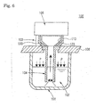
- a low-pressure die-casting apparatus 100 used to produce an aluminum casting or the like is configured so that an aluminum molten metal 102 contained in a molten metal container 101 is supplied to a die 105 through a stalk 104 and an intermediate stalk 103, and cast using the die 105.
- the intermediate stalk 103 used for the low-pressure die-casting apparatus 100 must withstand a molten metal temperature of 600 to 700°C and make it unnecessary to provide an external heating system, for example.
- an intermediate stalk in which the inner side of a metal covering material 113 is lined with a refractory heat insulator 123 has been known.
- JP-A-2006-272448 discloses the intermediate stalk 103 in which the inner side of the metal covering material 113 is lined with the refractory heat insulator 123, and an inorganic material 133 that adjusts and absorbs the difference in thermal expansion between the covering material 113 and the refractory heat insulator 123 is interposed between the covering material 113 and the refractory heat insulator 123, and also discloses the low-pressure die-casting apparatus 100 including the intermediate stalk 103.
- the intermediate stalk 103 and the low-pressure die-casting apparatus 100 have advantages in that radiation of heat from the intermediate stalk 103 is suppressed so that a decrease in temperature of the molten metal is prevented; cracks that may occur in the refractory heat insulator 123 due to the difference in thermal expansion between the covering material 113 and the refractory heat insulator 123 can be prevented by providing the inorganic material 133 that adjusts and absorbs the difference in thermal expansion between the covering material 113 and the refractory heat insulator 123; and an opening that may be formed between the covering material 113 and the refractory heat insulator 123 due to the difference in thermal expansion is closed by utilizing a thermally expansible sheet that expands due to heating as the inorganic material 133 so that a deterioration in heat insulation effect is prevented, for example.
- the inorganic material 133 provided between the refractory heat insulator 123 and the metal covering material 113 cannot sufficiently absorb the difference in thermal expansion between the refractory heat insulator 123 and the metal covering material 113, so that cracks may occur in the refractory heat insulator 123 due to heating during actual use. Since a significant force may be applied to the metal covering material 113 when destroying the refractory heat insulator 123 for replacement, the covering material 113 may break or may be deformed. Furthermore, an adhesive used to bond the inorganic material 133 or a water repellent for the inorganic material 133 may be decomposed to produce smoke or odor due to initial heating during production or actual use.
- water contained in the refractory heat insulator consists of a residue of water used during lining when producing the refractory heat insulator and water absorbed by the refractory heat insulator during storage.
- An object of the present invention is to provide an intermediate stalk that allows water to be sufficiently released from a refractory material during heating, does not explode, does not produce cracks in the refractory material due to the difference in coefficient of thermal expansion between the refractory material and a metal covering material, and allows easy replacement of the refractory material, a method of producing the same, and a low-pressure die-casting apparatus.
- the inventors of the present invention conducted extensive studies in order to achieve the above object. As a result, the inventors found that water is sufficiently released from the refractory material during heating, an explosion does not occur, cracks do not occur in the refractory material due to the difference in coefficient of thermal expansion between the refractory material and the metal covering material, and the refractory material can be easily replaced by removably fitting a precast refractory material into a metal covering material, and forming an air release opening between the covering material and the precast refractory material when viewed from above. This finding has led to the completion of the present invention.
- the present invention provides an intermediate stalk that is used for a low-pressure die-casting apparatus, the intermediate stalk comprising a metal covering material, and a precast refractory material that is removably fitted into the metal covering material, an air release opening being formed between the metal covering material and the precast refractory material when viewed from above.
- the present invention also provides a low-pressure die-casting apparatus comprising the above intermediate stalk.
- the present invention further provides a method of producing an intermediate stalk that is used for a low-pressure die-casting apparatus, the method comprising fitting a precast refractory material into a metal covering material, the precast refractory material being formed in advance so that an air release opening is formed between the metal covering material and the precast refractory material when viewed from above in a state in which the precast refractory material is fitted into the metal covering material.
- the intermediate stalk and the low-pressure die-casting apparatus are configured so that the precast refractory material is removably fitted into the metal covering material and the air release opening is formed between the covering material and the precast refractory material when viewed from above, water is sufficiently released from the refractory material during heating, an explosion does not occur, cracks do not occur in the refractory material due to the difference in coefficient of thermal expansion between the refractory material and the metal covering material, and the refractory material can be easily replaced. Moreover, since it is unnecessary to replace the refractory material for maintenance purposes, a problem in which the metallic covering material is damaged due to replacement does not occur.
- the production method, the production apparatus, and the like can be conveniently determined so that the degree of freedom of production increases. Moreover, since the intermediate stalk can be substantially produced by merely fitting the precast refractory material into the metal covering material, the production cost can be reduced.
- FIG. 1 is a cross-sectional view showing the intermediate stalk according to this embodiment.
- FIG. 2 is a plan view of the intermediate stalk shown in FIG. 1 .
- FIG. 3 is a view showing an example of a method of securing a precast refractory material in the intermediate stalk, wherein (A) is a plan view showing another embodiment of an area enclosed by a two-dot chain line in FIG. 2 , (B) is a front view of (A), (C) is a front view showing an area secured by a securing plate, and (D) is a plan view of (C).
- FIG. 4 is a view illustrative of a method of producing the intermediate stalk according to the present invention.
- FIG. 5 is a schematic view showing a low-pressure die-casting apparatus.
- An intermediate stalk 10 is used for a low-pressure die-casting apparatus.
- the intermediate stalk 10 includes a metal covering material 2 that is in the shape of a relatively shallow holding bath and has an upper opening 27 having a large opening size and a lower opening 28 that has an opening size smaller than that of the upper opening 27, and a precast refractory material 1 that has almost the same shape as the covering material 2 and is removably fitted into the metal covering material 2.
- An intermediate stalk has been normally produced using a metal covering material as a molding box since the inner side of the metal covering material is lined with a refractory material. This poses limitations on the production conditions.
- the intermediate stalk according to the present invention is not produced using the metal covering material as a molding box, the production method, the production apparatus, and the like can be conveniently determined so that the degree of freedom of production increases. Moreover, since it is unnecessary to replace the refractory material for maintenance purposes, a problem in which the metal covering material is damaged due to replacement does not occur.
- the material for the metal covering material 2 is not particularly limited.
- the metal covering material 2 may be formed of cast iron.
- the shape of the metal covering material 2 is not particularly limited. It is preferable that a flat horizontal section 21 that supports the precast refractory material 1 be provided around the lower opening. The placement stability of the precast refractory material 1 having a flat horizontal bottom can be improved by providing the flat horizontal section 21 around the lower opening.
- the precast refractory material 1 is removably fitted into the metal covering material 2.
- the precast refractory material 1 may be arbitrarily fitted into the metal covering material 2 insofar as an air release opening 3 is formed between the covering material 2 and the precast refractory material 1 when viewed from above.
- the intermediate stalk 10 according to the present invention is configured so that the precast refractory material 1 is supported at the bottom. Specifically, a flat horizontal bottom 11 is formed at the bottom of the precast refractory material 1 around the opening of the metal covering material 2.
- the flat horizontal bottom 11 of the precast refractory material 1 is disposed on the flat horizontal section 21 of the metal covering material 2 through a packing material 4.
- a situation in which molten metal leaks through the opening between the precast refractory material 1 and the metal covering material 2 can be prevented by providing the packing material 4 in the area where the precast refractory material 1 is supported by (comes in contact with) the metal covering material 2.
- the packing material may be a sheet material that contains 20 to 40 mass% of ceramics fibers, 40 to 70 mass% of unfired vermiculite, and 5 to 20 mass% of an organic binder, for example.
- the density of such a thermally expansible sheet is preferably 500 to 800 kg/cm 3 , and particularly preferably 600 to 700 kg/cm 3 .
- the precast refractory material 1 may be fitted into the metal covering material 2 so that part of the outer side surface (outer circumferential surface) of the precast refractory material 1 is supported by part of the inner side surface (inner circumferential surface) of the metal covering material 2 (e.g., almost the lower half of the outer side surface of the precast refractory material 1 is supported by almost the lower half of the inner side surface of the metal covering material 2). Since an opening through which the air is released upward is formed even if part of the outer side surface of the precast refractory material 1 comes in contact with part of the inner side surface of the metal covering material 2, release of water from the refractory material during heating is not hindered.
- the air release opening 3 is formed between the covering material 2 and the precast refractory material 1 when viewed from above. This means that the opening 3 is observed between the metal covering material 2 and the precast refractory material 1 when observing the intermediate stalk 10 from above, as shown in FIG. 2 . Since the air release opening 3 is formed between the covering material 2 and the precast refractory material 1 when viewed from above, water is sufficiently released from the refractory material during heating, an explosion does not occur, cracks do not occur in the refractory material due to the difference in coefficient of thermal expansion between the refractory material and the metal covering material, and the refractory material can be easily replaced.
- the width of the opening 3 is 0.5 mm or more, preferably 1.0 mm or more, and particularly preferably 2.0 mm or more.
- the upper limit of the width of the opening 3 is not particularly limited, but is about 5 mm since the placement stability of the precast refractory material 1 decreases if the width of the opening 3 is too large.
- the opening 3 need not be formed between the metal covering material 2 and the precast refractory material 1 over the entire circumference of the intermediate stalk 10, or may be formed between the metal covering material 2 and the precast refractory material 1 over the entire circumference of the intermediate stalk 10. It is preferable that the opening 3 be formed between the metal covering material 2 and the precast refractory material 1 over the entire circumference of the intermediate stalk 10 from the viewpoint of ease of design and the placement stability of the precast refractory material 1.
- the opening 3 formed between the metal covering material 2 and the precast refractory material 1 may be connected to an internal opening 3a that is formed between an inner circumferential surface 25 of the metal covering material 2 and an outer circumferential surface 15 of the precast refractory material 1.
- the opening 3 formed between the metal covering material 2 and the precast refractory material 1 is connected to an opening formed between almost the upper half of the inner side surface of metal covering material 2 and almost the upper half of the outer side surface of the precast refractory material 1.
- the precast refractory material 1 may be formed using a known insulating material.
- the precast refractory material 1 may be formed using an unshaped refractory material.
- the unshaped refractory material include a material obtained by adding an alumina cement binder and water to calcium silicate or silica (main component) and kneading the mixture, a paste material obtained by adding mica, carbon, a silicon carbide powder, or a silicon nitride powder (non-wettability improver) to inorganic fibers and an alumina powder, adding a silica or alumina-based inorganic binder, a thickener, and water to the mixture, and kneading the mixture, and the like.
- a heat insulator may be formed on the outer circumferential surface of the precast refractory material 1.
- the heat insulating properties of the intermediate stalk can be improved by forming the heat insulator on the outer circumferential surface of the precast refractory material 1 (i.e., lining the precast refractory material 1 with the heat insulator) so that a problem due to a decrease in temperature of molten metal can be prevented.
- the heat insulator also functions as a sealing material that prevents leakage of molten metal due to cracks formed in the precast refractory material 1. Examples of the heat insulator include inorganic fiber aggregates (e.g., inorganic fiber felt and blanket) and the like.
- the inorganic fibers include ceramic fibers, silica fibers, alumina fibers, and the like. Even if the heat insulator is formed on the outer circumferential surface of the precast refractory material 1, the air release opening 3 is formed between the covering material 2 and the precast refractory material 1 provided with the heat insulator when viewed from above.
- the internal opening 3a may be formed between the inner circumferential surface 25 of the metal covering material 2 and the outer circumferential surface of the heat insulator formed on the precast refractory material 1.
- the intermediate stalk 10 may have a structure in which a thermally expansible sheet that has flexibility and expands due to heating is provided in part of the area (particularly the lower half) between the metal covering material 2 and the precast refractory material 1. This improves the placement stability of the precast refractory material 1.
- the thermally expansible sheet starts to expand at 300 to 400°C, for example, and expands in the thickness direction.
- the expansion coefficient is 2, and preferably 2 to 4 in the thickness direction. If the expansion coefficient is within the above range, an opening is not formed between the metal covering material 2 and the precast refractory material 1 in the area where the thermally expansible sheet is provided, so that the placement stability of the precast refractory material 1 can be improved while ensuring a heat insulation effect.
- reference numeral 5 indicates a grip of the metal covering material 2.
- the four corners or two diagonal corners of the precast refractory material 1 fitted into the metal covering material 2 may be secured using a securing plate.
- This enables the precast refractory material 1 to be stably secured.
- a securing method using the securing plate is described below with reference to FIG. 3 .
- the corner of the upper end of the intermediate stalk 10 is provided with a depression 6 that is approximately in the shape of a triangle when viewed from above and has a given dimension in the depth direction.
- the depression 6 includes a depression 61 formed in the metal covering material 2, and a depression 62 formed in the precast refractory material 1.
- a bolt hole 7 is formed in the depression 61 formed in the metal covering material 2 ( FIG. 3(A) ).
- a securing plate 8 that is fitted into the depression 6 is provided.
- the securing plate 8 has a through-hole that receives a flush bolt 9 and is formed at a position opposite to the bolt hole 7 after installation ( FIG. 3(B) ).
- the precast refractory material 1 is strongly secured on the metal covering material 2 due to repulsion of the flexible packing material 4 provided at the bottom ( FIGS. 3(C) and 3(D) ).
- the intermediate stalk 10 according to the present invention is produced by fitting the precast refractory material 1 into the metal covering material 2, the precast refractory material 1 being formed in advance so that the air release opening 3 is formed between the metal covering material 2 and the precast refractory material 1 when viewed from above in a state in which the precast refractory material 1 is fitted into the metal covering material 2.
- the precast refractory material 1 is produced using an unshaped refractory material described with regard to the intermediate stalk 10 according to the present invention. Since the precast refractory material 1 is not produced using the metal covering material 2 as a molding box, the production method, the production apparatus, and the like can be conveniently determined so that the degree of freedom of production increases.
- the metal covering material 2 and the refractory material are integrally formed (e.g., related-art intermediate stalk)
- the metal covering material 2 since the metal covering material 2 is oxidized and deformed when the heating temperature during production is increased, it is necessary to employ a low heating temperature. In this case, since water remaining in the refractory material may vaporize or shrinkage due to heating may occur during actual use, the refractory material may break.
- the precast refractory material 1 can be fired in advance at a high temperature. This prevents a situation in which water remaining in the refractory material vaporizes or shrinkage due to heating occurs during actual use. Moreover, since the intermediate stalk 10 can be substantially produced by merely fitting the precast refractory material 1 into the metal covering material 2, the production cost can be reduced.
- the packing material 4 is disposed at a given position around the bottom opening of the intermediate stalk 10 before fitting the precast refractory material 1 into the metal covering material 2 ( FIG. 4 ). This enables the intermediate stalk 10 to be produced by a simple method.
- a low-pressure die-casting apparatus 20 includes the intermediate stalk 10.
- the low-pressure die-casting apparatus 20 includes a molten metal container 31 (crucible) that contains molten metal 32, a furnace cover 36 that seals the molten metal container, a stalk tube 34 that is disposed at the center of the furnace cover 36 so that the stalk tube 34 passes through the furnace cover 36 and the lower opening of the stalk tube 34 is positioned in the molten metal 32, the intermediate stalk 10 that is disposed so that the upper opening of the stalk tube 34 communicates with the bottom opening of the intermediate stalk 10, and a die 35 that is disposed over the intermediate stalk 10.
- the molten metal 32 contained in the molten metal container 31 is heated and melted using a heating means (not shown).
- a pressure (pressurized air) indicated by arrows P is applied to the surface of the molten metal 32 using a means not shown in FIG. 5 so that the molten metal 32 moves upward toward the die 35 through the stalk tube 34 and the intermediate stalk 10 (molten metal passage).
- An air vent hole (not shown) is formed in the top of the die 35 so that unnecessary air is removed through the air vent hole.
- FIG. 5 shows the structure of the low-pressure die-casting apparatus that causes the molten metal to move upward and to be supplied to the die
- the low-pressure die-casting apparatus may have a structure in which the pressure inside the die 35 is reduced to suck up the molten metal, or a structure in which the molten metal is caused to move upward at a positive pressure while reducing the pressure inside the die 35, for example.
- the low-pressure die-casting apparatus 20 is configured so that the air release opening is formed between the covering material and the precast refractory material when viewed from above, water is sufficiently released from the refractory material during heating, an explosion does not occur, cracks do not occur in the refractory material due to the difference in coefficient of thermal expansion between the refractory material and the metal covering material, and the refractory material can be easily replaced. Moreover, since it is unnecessary to replace the refractory material for maintenance purposes, a problem in which the metallic covering material is damaged due to replacement does not occur.
- a ceramic fiber sheet material (packing material) containing unfired vermiculite and provided with a hole having the same shape as the bottom opening of a covering material was disposed at the bottom of a covering material formed of cast iron and having a shape shown in FIGS. 1 and 2 .
- the precast refractory material produced by the above method was disposed inside the covering material on which the packing material was disposed, and a securing plate was attached to each of two diagonal corners over the covering material to obtain an intermediate stalk.
- the intermediate stalk had an opening (width: 3 mm) between the covering material and the precast refractory material over the entire circumference of the intermediate stalk when viewed from above.
- a ceramic fiber sheet material containing unfired vermiculite was bonded to the entire inner circumference of a covering material formed of cast iron and having a shape shown in FIGS. 1 and 2 using an organic adhesive.
- a core for forming the inner surface (inner lining material) of an intermediate stalk was disposed inside the covering material.
- the mortar used in Example 1 was injected between the covering material and the core, and cured and hardened overnight at a temperature of 25°C and a relative humidity of 80%. After removing the core, the product was dried at 110°C for 24 hours. The resulting intermediate stalk did not have an opening between the covering material and the lining material when viewed from above.
- the inside of the intermediate stalk was rapidly heated using a gas burner until the temperature of the atmosphere inside the intermediate stalk reached 900°C as a simulation of actual use of a low-pressure die-casting apparatus.
- White smoke due to the organic adhesive was produced from the intermediate stalk obtained in Comparative Example 1.
- the state of the refractory material after heating was visually inspected. Cracks that are considered to be caused by the difference in thermal expansion and removal of the refractory material due to explosion were observed.
- no abnormalities were observed during and after heating.
- the intermediate stalk and the low-pressure die-casting apparatus according to the present invention allow water to be sufficiently released from the refractory material during heating, do not explode, and do not produce cracks in the refractory material due to the difference in coefficient of thermal expansion between the refractory material and the metal covering material
- the intermediate stalk and the low-pressure die-casting apparatus according to the present invention may be suitably used to produce an aluminum casting or the like.
- the production method, the production apparatus, and the like can be conveniently determined so that the degree of freedom of production increases.
Landscapes
- Engineering & Computer Science (AREA)
- Mechanical Engineering (AREA)
- Furnace Housings, Linings, Walls, And Ceilings (AREA)
- Incineration Of Waste (AREA)
- Building Environments (AREA)
Abstract
Description
- The present invention relates to an intermediate stalk for a low-pressure die-casting apparatus used to produce an aluminum casting or the like, and a method of producing the same.
- As shown in
FIG. 6 , a low-pressure die-casting apparatus 100 used to produce an aluminum casting or the like is configured so that an aluminummolten metal 102 contained in amolten metal container 101 is supplied to adie 105 through astalk 104 and anintermediate stalk 103, and cast using thedie 105. - The
intermediate stalk 103 used for the low-pressure die-casting apparatus 100 must withstand a molten metal temperature of 600 to 700°C and make it unnecessary to provide an external heating system, for example. In recent years, an intermediate stalk in which the inner side of ametal covering material 113 is lined with arefractory heat insulator 123 has been known. -
JP-A-2006-272448 intermediate stalk 103 in which the inner side of themetal covering material 113 is lined with therefractory heat insulator 123, and aninorganic material 133 that adjusts and absorbs the difference in thermal expansion between the coveringmaterial 113 and therefractory heat insulator 123 is interposed between the coveringmaterial 113 and therefractory heat insulator 123, and also discloses the low-pressure die-casting apparatus 100 including theintermediate stalk 103. Theintermediate stalk 103 and the low-pressure die-casting apparatus 100 have advantages in that radiation of heat from theintermediate stalk 103 is suppressed so that a decrease in temperature of the molten metal is prevented; cracks that may occur in therefractory heat insulator 123 due to the difference in thermal expansion between the coveringmaterial 113 and therefractory heat insulator 123 can be prevented by providing theinorganic material 133 that adjusts and absorbs the difference in thermal expansion between the coveringmaterial 113 and therefractory heat insulator 123; and an opening that may be formed between the coveringmaterial 113 and therefractory heat insulator 123 due to the difference in thermal expansion is closed by utilizing a thermally expansible sheet that expands due to heating as theinorganic material 133 so that a deterioration in heat insulation effect is prevented, for example. - According to the
intermediate stalk 103 and the low-pressure die-casting apparatus 100 including the same disclosed inJP-A-2006-272448 material 113, water may not be sufficiently released from therefractory heat insulator 123 during heating so that therefractory heat insulator 123 may break due to vaporization and expansion of water contained in therefractory heat insulator 123. Moreover, theinorganic material 133 provided between therefractory heat insulator 123 and themetal covering material 113 cannot sufficiently absorb the difference in thermal expansion between therefractory heat insulator 123 and themetal covering material 113, so that cracks may occur in therefractory heat insulator 123 due to heating during actual use. Since a significant force may be applied to themetal covering material 113 when destroying therefractory heat insulator 123 for replacement, the coveringmaterial 113 may break or may be deformed. Furthermore, an adhesive used to bond theinorganic material 133 or a water repellent for theinorganic material 133 may be decomposed to produce smoke or odor due to initial heating during production or actual use. - Note that water contained in the refractory heat insulator consists of a residue of water used during lining when producing the refractory heat insulator and water absorbed by the refractory heat insulator during storage.
- An object of the present invention is to provide an intermediate stalk that allows water to be sufficiently released from a refractory material during heating, does not explode, does not produce cracks in the refractory material due to the difference in coefficient of thermal expansion between the refractory material and a metal covering material, and allows easy replacement of the refractory material, a method of producing the same, and a low-pressure die-casting apparatus.
- The inventors of the present invention conducted extensive studies in order to achieve the above object. As a result, the inventors found that water is sufficiently released from the refractory material during heating, an explosion does not occur, cracks do not occur in the refractory material due to the difference in coefficient of thermal expansion between the refractory material and the metal covering material, and the refractory material can be easily replaced by removably fitting a precast refractory material into a metal covering material, and forming an air release opening between the covering material and the precast refractory material when viewed from above. This finding has led to the completion of the present invention.
- Specifically, the present invention provides an intermediate stalk that is used for a low-pressure die-casting apparatus, the intermediate stalk comprising a metal covering material, and a precast refractory material that is removably fitted into the metal covering material, an air release opening being formed between the metal covering material and the precast refractory material when viewed from above.
- The present invention also provides a low-pressure die-casting apparatus comprising the above intermediate stalk.
- The present invention further provides a method of producing an intermediate stalk that is used for a low-pressure die-casting apparatus, the method comprising fitting a precast refractory material into a metal covering material, the precast refractory material being formed in advance so that an air release opening is formed between the metal covering material and the precast refractory material when viewed from above in a state in which the precast refractory material is fitted into the metal covering material.
- Since the intermediate stalk and the low-pressure die-casting apparatus according to the present invention are configured so that the precast refractory material is removably fitted into the metal covering material and the air release opening is formed between the covering material and the precast refractory material when viewed from above, water is sufficiently released from the refractory material during heating, an explosion does not occur, cracks do not occur in the refractory material due to the difference in coefficient of thermal expansion between the refractory material and the metal covering material, and the refractory material can be easily replaced. Moreover, since it is unnecessary to replace the refractory material for maintenance purposes, a problem in which the metallic covering material is damaged due to replacement does not occur. According to the method of producing an intermediate stalk according to the present invention, since the precast refractory material is not produced using the metal covering material as a molding box, the production method, the production apparatus, and the like can be conveniently determined so that the degree of freedom of production increases. Moreover, since the intermediate stalk can be substantially produced by merely fitting the precast refractory material into the metal covering material, the production cost can be reduced.
-
-
FIG. 1 is a cross-sectional view showing an intermediate stalk according to one embodiment of the present invention,FIG. 2 is a plan view of the intermediate stalk shown inFIG. 1 ,FIG. 3 is a view showing an example of a method of securing a precast refractory material in the intermediate stalk, wherein (A) is a plan view showing another embodiment of an area enclosed by a two-dot chain line inFIG. 2 , (B) is a front view of (A), (C) is a front view showing an area secured by a securing plate, and (D) is a plan view of (C),FIG. 4 is a view illustrative of a method of producing an intermediate stalk according to the present invention,FIG. 5 is a schematic view showing a low-pressure die-casting apparatus according to the present invention, andFIG. 6 is a schematic view showing a related-art low-pressure die-casting apparatus. - An intermediate stalk according to one embodiment of the present invention and a low-pressure die-casting apparatus including the same are described below with reference to
FIGS. 1 to 5 .FIG. 1 is a cross-sectional view showing the intermediate stalk according to this embodiment.FIG. 2 is a plan view of the intermediate stalk shown inFIG. 1 .FIG. 3 is a view showing an example of a method of securing a precast refractory material in the intermediate stalk, wherein (A) is a plan view showing another embodiment of an area enclosed by a two-dot chain line inFIG. 2 , (B) is a front view of (A), (C) is a front view showing an area secured by a securing plate, and (D) is a plan view of (C).FIG. 4 is a view illustrative of a method of producing the intermediate stalk according to the present invention.FIG. 5 is a schematic view showing a low-pressure die-casting apparatus. - An
intermediate stalk 10 is used for a low-pressure die-casting apparatus. Theintermediate stalk 10 includes ametal covering material 2 that is in the shape of a relatively shallow holding bath and has anupper opening 27 having a large opening size and alower opening 28 that has an opening size smaller than that of theupper opening 27, and a precastrefractory material 1 that has almost the same shape as the coveringmaterial 2 and is removably fitted into themetal covering material 2. An intermediate stalk has been normally produced using a metal covering material as a molding box since the inner side of the metal covering material is lined with a refractory material. This poses limitations on the production conditions. On the other hand, since the intermediate stalk according to the present invention is not produced using the metal covering material as a molding box, the production method, the production apparatus, and the like can be conveniently determined so that the degree of freedom of production increases. Moreover, since it is unnecessary to replace the refractory material for maintenance purposes, a problem in which the metal covering material is damaged due to replacement does not occur. - The material for the
metal covering material 2 is not particularly limited. For example, themetal covering material 2 may be formed of cast iron. The shape of themetal covering material 2 is not particularly limited. It is preferable that a flathorizontal section 21 that supports the precastrefractory material 1 be provided around the lower opening. The placement stability of the precastrefractory material 1 having a flat horizontal bottom can be improved by providing the flathorizontal section 21 around the lower opening. - In the
intermediate stalk 10 according to the present invention, the precastrefractory material 1 is removably fitted into themetal covering material 2. The precastrefractory material 1 may be arbitrarily fitted into themetal covering material 2 insofar as anair release opening 3 is formed between the coveringmaterial 2 and the precastrefractory material 1 when viewed from above. Theintermediate stalk 10 according to the present invention is configured so that the precastrefractory material 1 is supported at the bottom. Specifically, a flathorizontal bottom 11 is formed at the bottom of the precastrefractory material 1 around the opening of themetal covering material 2. The flathorizontal bottom 11 of the precastrefractory material 1 is disposed on the flathorizontal section 21 of themetal covering material 2 through apacking material 4. A situation in which molten metal leaks through the opening between the precastrefractory material 1 and themetal covering material 2 can be prevented by providing thepacking material 4 in the area where the precastrefractory material 1 is supported by (comes in contact with) themetal covering material 2. - The packing material may be a sheet material that contains 20 to 40 mass% of ceramics fibers, 40 to 70 mass% of unfired vermiculite, and 5 to 20 mass% of an organic binder, for example. The density of such a thermally expansible sheet is preferably 500 to 800 kg/cm3, and particularly preferably 600 to 700 kg/cm3.
- The precast
refractory material 1 may be fitted into themetal covering material 2 so that part of the outer side surface (outer circumferential surface) of the precastrefractory material 1 is supported by part of the inner side surface (inner circumferential surface) of the metal covering material 2 (e.g., almost the lower half of the outer side surface of the precastrefractory material 1 is supported by almost the lower half of the inner side surface of the metal covering material 2). Since an opening through which the air is released upward is formed even if part of the outer side surface of the precastrefractory material 1 comes in contact with part of the inner side surface of themetal covering material 2, release of water from the refractory material during heating is not hindered. - In the
intermediate stalk 10 according to the present invention, theair release opening 3 is formed between the coveringmaterial 2 and the precastrefractory material 1 when viewed from above. This means that theopening 3 is observed between themetal covering material 2 and the precastrefractory material 1 when observing theintermediate stalk 10 from above, as shown inFIG. 2 . Since theair release opening 3 is formed between the coveringmaterial 2 and the precastrefractory material 1 when viewed from above, water is sufficiently released from the refractory material during heating, an explosion does not occur, cracks do not occur in the refractory material due to the difference in coefficient of thermal expansion between the refractory material and the metal covering material, and the refractory material can be easily replaced. - In the
intermediate stalk 10, the width of theopening 3 is 0.5 mm or more, preferably 1.0 mm or more, and particularly preferably 2.0 mm or more. The upper limit of the width of theopening 3 is not particularly limited, but is about 5 mm since the placement stability of the precastrefractory material 1 decreases if the width of theopening 3 is too large. The opening 3 need not be formed between themetal covering material 2 and the precastrefractory material 1 over the entire circumference of theintermediate stalk 10, or may be formed between themetal covering material 2 and the precastrefractory material 1 over the entire circumference of theintermediate stalk 10. It is preferable that theopening 3 be formed between themetal covering material 2 and the precastrefractory material 1 over the entire circumference of theintermediate stalk 10 from the viewpoint of ease of design and the placement stability of the precastrefractory material 1. - As shown in
FIG. 1 , theopening 3 formed between themetal covering material 2 and the precastrefractory material 1 may be connected to aninternal opening 3a that is formed between an innercircumferential surface 25 of themetal covering material 2 and an outercircumferential surface 15 of the precastrefractory material 1. For example, when almost the lower half of the outer side surface of the precastrefractory material 1 is supported by almost the lower half of the inner side surface ofmetal covering material 2, theopening 3 formed between themetal covering material 2 and the precastrefractory material 1 is connected to an opening formed between almost the upper half of the inner side surface ofmetal covering material 2 and almost the upper half of the outer side surface of the precastrefractory material 1. - The precast
refractory material 1 may be formed using a known insulating material. The precastrefractory material 1 may be formed using an unshaped refractory material. Examples of the unshaped refractory material include a material obtained by adding an alumina cement binder and water to calcium silicate or silica (main component) and kneading the mixture, a paste material obtained by adding mica, carbon, a silicon carbide powder, or a silicon nitride powder (non-wettability improver) to inorganic fibers and an alumina powder, adding a silica or alumina-based inorganic binder, a thickener, and water to the mixture, and kneading the mixture, and the like. - In the
intermediate stalk 10 according to the present invention, a heat insulator may be formed on the outer circumferential surface of the precastrefractory material 1. The heat insulating properties of the intermediate stalk can be improved by forming the heat insulator on the outer circumferential surface of the precast refractory material 1 (i.e., lining the precastrefractory material 1 with the heat insulator) so that a problem due to a decrease in temperature of molten metal can be prevented. The heat insulator also functions as a sealing material that prevents leakage of molten metal due to cracks formed in the precastrefractory material 1. Examples of the heat insulator include inorganic fiber aggregates (e.g., inorganic fiber felt and blanket) and the like. Examples of the inorganic fibers include ceramic fibers, silica fibers, alumina fibers, and the like. Even if the heat insulator is formed on the outer circumferential surface of the precastrefractory material 1, theair release opening 3 is formed between the coveringmaterial 2 and the precastrefractory material 1 provided with the heat insulator when viewed from above. Theinternal opening 3a may be formed between the innercircumferential surface 25 of themetal covering material 2 and the outer circumferential surface of the heat insulator formed on the precastrefractory material 1. - The
intermediate stalk 10 according to the present invention may have a structure in which a thermally expansible sheet that has flexibility and expands due to heating is provided in part of the area (particularly the lower half) between themetal covering material 2 and the precastrefractory material 1. This improves the placement stability of the precastrefractory material 1. The thermally expansible sheet starts to expand at 300 to 400°C, for example, and expands in the thickness direction. The expansion coefficient is 2, and preferably 2 to 4 in the thickness direction. If the expansion coefficient is within the above range, an opening is not formed between themetal covering material 2 and the precastrefractory material 1 in the area where the thermally expansible sheet is provided, so that the placement stability of the precastrefractory material 1 can be improved while ensuring a heat insulation effect. InFIG. 1 ,reference numeral 5 indicates a grip of themetal covering material 2. - In the
intermediate stalk 10 according to the present invention, the four corners or two diagonal corners of the precastrefractory material 1 fitted into themetal covering material 2 may be secured using a securing plate. This enables the precastrefractory material 1 to be stably secured. A securing method using the securing plate is described below with reference toFIG. 3 . The corner of the upper end of theintermediate stalk 10 is provided with a depression 6 that is approximately in the shape of a triangle when viewed from above and has a given dimension in the depth direction. The depression 6 includes adepression 61 formed in themetal covering material 2, and adepression 62 formed in the precastrefractory material 1. A bolt hole 7 is formed in thedepression 61 formed in the metal covering material 2 (FIG. 3(A) ). A securingplate 8 that is fitted into the depression 6 is provided. The securingplate 8 has a through-hole that receives aflush bolt 9 and is formed at a position opposite to the bolt hole 7 after installation (FIG. 3(B) ). When the securingplate 8 is fitted into the depression 6 and secured using the bolt, the precastrefractory material 1 is strongly secured on themetal covering material 2 due to repulsion of theflexible packing material 4 provided at the bottom (FIGS. 3(C) and 3(D) ). - A method of producing the intermediate stalk according to the present invention is described below. The
intermediate stalk 10 according to the present invention is produced by fitting the precastrefractory material 1 into themetal covering material 2, the precastrefractory material 1 being formed in advance so that theair release opening 3 is formed between themetal covering material 2 and the precastrefractory material 1 when viewed from above in a state in which the precastrefractory material 1 is fitted into themetal covering material 2. - The precast
refractory material 1 is produced using an unshaped refractory material described with regard to theintermediate stalk 10 according to the present invention. Since the precastrefractory material 1 is not produced using themetal covering material 2 as a molding box, the production method, the production apparatus, and the like can be conveniently determined so that the degree of freedom of production increases. When themetal covering material 2 and the refractory material are integrally formed (e.g., related-art intermediate stalk), since themetal covering material 2 is oxidized and deformed when the heating temperature during production is increased, it is necessary to employ a low heating temperature. In this case, since water remaining in the refractory material may vaporize or shrinkage due to heating may occur during actual use, the refractory material may break. On the other hand, since theintermediate stalk 10 according to the present invention is not produced using themetal covering material 2 as a molding box, the precastrefractory material 1 can be fired in advance at a high temperature. This prevents a situation in which water remaining in the refractory material vaporizes or shrinkage due to heating occurs during actual use. Moreover, since theintermediate stalk 10 can be substantially produced by merely fitting the precastrefractory material 1 into themetal covering material 2, the production cost can be reduced. - When the
intermediate stalk 10 includes the packingmaterial 4, the packingmaterial 4 is disposed at a given position around the bottom opening of theintermediate stalk 10 before fitting the precastrefractory material 1 into the metal covering material 2 (FIG. 4 ). This enables theintermediate stalk 10 to be produced by a simple method. - A low-pressure die-casting
apparatus 20 according to the present invention includes theintermediate stalk 10. As shown inFIG. 5 , the low-pressure die-castingapparatus 20 according to the present invention includes a molten metal container 31 (crucible) that containsmolten metal 32, a furnace cover 36 that seals the molten metal container, astalk tube 34 that is disposed at the center of the furnace cover 36 so that thestalk tube 34 passes through the furnace cover 36 and the lower opening of thestalk tube 34 is positioned in themolten metal 32, theintermediate stalk 10 that is disposed so that the upper opening of thestalk tube 34 communicates with the bottom opening of theintermediate stalk 10, and a die 35 that is disposed over theintermediate stalk 10. - In the low-pressure die-casting
apparatus 20 according to the present invention, themolten metal 32 contained in themolten metal container 31 is heated and melted using a heating means (not shown). A pressure (pressurized air) indicated by arrows P is applied to the surface of themolten metal 32 using a means not shown inFIG. 5 so that themolten metal 32 moves upward toward the die 35 through thestalk tube 34 and the intermediate stalk 10 (molten metal passage). An air vent hole (not shown) is formed in the top of the die 35 so that unnecessary air is removed through the air vent hole. - A mold that corresponds to the casting target product is disposed in the
die 35. Themolten metal 32 that has moved upward flows into the mold. The die is cooled at an appropriate timing to obtain a casting (e.g., aluminum casting). AlthoughFIG. 5 shows the structure of the low-pressure die-casting apparatus that causes the molten metal to move upward and to be supplied to the die, the low-pressure die-casting apparatus may have a structure in which the pressure inside thedie 35 is reduced to suck up the molten metal, or a structure in which the molten metal is caused to move upward at a positive pressure while reducing the pressure inside thedie 35, for example. - Since the low-pressure die-casting
apparatus 20 according to the present invention is configured so that the air release opening is formed between the covering material and the precast refractory material when viewed from above, water is sufficiently released from the refractory material during heating, an explosion does not occur, cracks do not occur in the refractory material due to the difference in coefficient of thermal expansion between the refractory material and the metal covering material, and the refractory material can be easily replaced. Moreover, since it is unnecessary to replace the refractory material for maintenance purposes, a problem in which the metallic covering material is damaged due to replacement does not occur. - The present invention is further described below by way of examples. Note that the present invention is not limited to the following examples.
- An appropriate amount of water was added to an unshaped refractory material containing silica (main component) and alumina cement (binder). The mixture was kneaded to prepare mortar. The mortar was injected into a resin mold having a given shape, and cured and hardened overnight at a temperature of 25°C and a relative humidity of 80%. The hardened molding was dried at 110°C for 24 hours, and fired at 600°C for 12 hours to obtain a precast refractory material having a shape shown in
FIGS. 1 and 2 . - A ceramic fiber sheet material (packing material) containing unfired vermiculite and provided with a hole having the same shape as the bottom opening of a covering material was disposed at the bottom of a covering material formed of cast iron and having a shape shown in
FIGS. 1 and 2 . The precast refractory material produced by the above method was disposed inside the covering material on which the packing material was disposed, and a securing plate was attached to each of two diagonal corners over the covering material to obtain an intermediate stalk. The intermediate stalk had an opening (width: 3 mm) between the covering material and the precast refractory material over the entire circumference of the intermediate stalk when viewed from above. - A ceramic fiber sheet material containing unfired vermiculite was bonded to the entire inner circumference of a covering material formed of cast iron and having a shape shown in
FIGS. 1 and 2 using an organic adhesive. A core for forming the inner surface (inner lining material) of an intermediate stalk was disposed inside the covering material. The mortar used in Example 1 was injected between the covering material and the core, and cured and hardened overnight at a temperature of 25°C and a relative humidity of 80%. After removing the core, the product was dried at 110°C for 24 hours. The resulting intermediate stalk did not have an opening between the covering material and the lining material when viewed from above. - The inside of the intermediate stalk was rapidly heated using a gas burner until the temperature of the atmosphere inside the intermediate stalk reached 900°C as a simulation of actual use of a low-pressure die-casting apparatus. White smoke due to the organic adhesive was produced from the intermediate stalk obtained in Comparative Example 1. The state of the refractory material after heating was visually inspected. Cracks that are considered to be caused by the difference in thermal expansion and removal of the refractory material due to explosion were observed. When subjecting the intermediate stalk obtained in Example 1 to the same evaluation test, no abnormalities were observed during and after heating.
-
- 1: Precast refractory material
- 2: Metal covering material
- 3: Air release opening
- 4: Packing material
- 5: Grip
- 10, 103: Intermediate stalk
- 20, 100: Low-pressure die-casting apparatus
- 31: Molten metal container (crucible)
- 32: Molten metal
- 34: Stalk tube
- 35: Die
- 36: Furnace cover
- Since the intermediate stalk and the low-pressure die-casting apparatus according to the present invention allow water to be sufficiently released from the refractory material during heating, do not explode, and do not produce cracks in the refractory material due to the difference in coefficient of thermal expansion between the refractory material and the metal covering material, the intermediate stalk and the low-pressure die-casting apparatus according to the present invention may be suitably used to produce an aluminum casting or the like. According to the method of producing an intermediate stalk according to the present invention, since the precast refractory material is not produced using the metal covering material as a molding box, the production method, the production apparatus, and the like can be conveniently determined so that the degree of freedom of production increases.
Claims (6)
- An intermediate stalk that is used for a low-pressure die-casting apparatus, the intermediate stalk comprising a metal covering material, and a precast refractory material that is removably fitted into the metal covering material, an air release opening being formed between the metal covering material and the precast refractory material when viewed from above.
- The intermediate stalk according to claim 1, wherein an opening having a width of 0.5 or more is formed between the covering material and the precast refractory material over the entire circumference of the intermediate stalk.
- The intermediate stalk according to claim 1 or 2, wherein a heat insulator is formed on an outer circumferential surface of the precast refractory material.
- The intermediate stalk according to any one of claims 1 to 3, wherein a packing material that prevents entrance of molten metal is provided between the precast refractory material and the covering material around a bottom opening of the intermediate stalk.
- A low-pressure die-casting apparatus comprising the intermediate stalk according to any one of claims 1 to 4.
- A method of producing an intermediate stalk that is used for a low-pressure die-casting apparatus, the method comprising fitting a precast refractory material into a metal covering material, the precast refractory material being formed in advance so that an air release opening is formed between the metal covering material and the precast refractory material when viewed from above in a state in which the precast refractory material is fitted into the metal covering material.
Applications Claiming Priority (2)
| Application Number | Priority Date | Filing Date | Title |
|---|---|---|---|
| JP2008181216A JP5255934B2 (en) | 2008-07-11 | 2008-07-11 | Intermediate stalk, manufacturing method thereof, and low pressure casting apparatus |
| PCT/JP2009/061155 WO2010004848A1 (en) | 2008-07-11 | 2009-06-12 | Intermediate stoke, method for producing the same and low pressure casting device |
Publications (2)
| Publication Number | Publication Date |
|---|---|
| EP2181784A1 true EP2181784A1 (en) | 2010-05-05 |
| EP2181784A4 EP2181784A4 (en) | 2013-03-13 |
Family
ID=41506968
Family Applications (1)
| Application Number | Title | Priority Date | Filing Date |
|---|---|---|---|
| EP09794295A Withdrawn EP2181784A4 (en) | 2008-07-11 | 2009-06-12 | INTERMEDIATE CARROT, PROCESS FOR PRODUCTION THEREOF, AND LOW PRESSURE CASTING DEVICE |
Country Status (5)
| Country | Link |
|---|---|
| US (1) | US20100326617A1 (en) |
| EP (1) | EP2181784A4 (en) |
| JP (1) | JP5255934B2 (en) |
| CN (1) | CN101801563B (en) |
| WO (1) | WO2010004848A1 (en) |
Families Citing this family (2)
| Publication number | Priority date | Publication date | Assignee | Title |
|---|---|---|---|---|
| DE102017109448A1 (en) * | 2017-05-03 | 2018-11-08 | EKW Gesellschaft mit beschränkter Haftung | Casting nozzle with exchangeable crown |
| JP7174845B2 (en) * | 2019-05-22 | 2022-11-17 | 本田技研工業株式会社 | Low pressure casting equipment |
Family Cites Families (17)
| Publication number | Priority date | Publication date | Assignee | Title |
|---|---|---|---|---|
| US3019496A (en) * | 1958-10-27 | 1962-02-06 | Bethlehem Steel Corp | Vacuum casting apparatus |
| US3430289A (en) * | 1965-11-01 | 1969-03-04 | Toho Zinc Co Ltd | Apparatus for preparing high purity fine powder of low-melting metals |
| US4345743A (en) * | 1980-10-10 | 1982-08-24 | Alcan Research And Development Limited | Means and method for containing flowing or standing molten metal |
| JPS63132762A (en) * | 1986-11-21 | 1988-06-04 | Ngk Insulators Ltd | Stoke for low pressure casting |
| US5011049A (en) * | 1989-04-17 | 1991-04-30 | General Electric Company | Molten metal transfer tube |
| JPH0447856U (en) * | 1990-08-27 | 1992-04-23 | ||
| JPH0523823A (en) | 1991-07-12 | 1993-02-02 | Hitachi Metals Ltd | Stoke for differential pressure casting |
| JPH0577023A (en) * | 1991-09-18 | 1993-03-30 | Tokyo Yogyo Co Ltd | Ceramic stalk for low pressure casting |
| JP2565327Y2 (en) * | 1992-03-24 | 1998-03-18 | 株式会社クボタ | Gate member of hot water supply channel in low pressure casting machine |
| JPH06621A (en) | 1992-06-16 | 1994-01-11 | Chubu Sukegawa Kogyo Kk | Sealing structure for molten metal supplying sleeve in casting apparatus |
| JP2532153Y2 (en) * | 1993-06-01 | 1997-04-09 | マツダ株式会社 | Stoke for casting |
| JP3339141B2 (en) * | 1993-11-05 | 2002-10-28 | 日立金属株式会社 | Ceramic stalk |
| DE19639358A1 (en) * | 1996-09-25 | 1998-03-26 | Bayer Ag | Riser pipe made of sintered ceramic material for use in light metal melts |
| JP3549430B2 (en) * | 1999-03-23 | 2004-08-04 | ニチアス株式会社 | Low pressure casting equipment |
| JP2005296959A (en) * | 2004-04-06 | 2005-10-27 | Hitachi Metals Ltd | Stalk for low pressure casting |
| JP4421506B2 (en) | 2005-03-30 | 2010-02-24 | ニチアス株式会社 | Intermediate Stoke Manufacturing Method |
| CN2822829Y (en) * | 2005-06-29 | 2006-10-04 | 冷星培 | Liquid-lifting tube of low pressure foundry machine |
-
2008
- 2008-07-11 JP JP2008181216A patent/JP5255934B2/en not_active Expired - Fee Related
-
2009
- 2009-06-12 CN CN2009801003771A patent/CN101801563B/en not_active Expired - Fee Related
- 2009-06-12 WO PCT/JP2009/061155 patent/WO2010004848A1/en not_active Ceased
- 2009-06-12 US US12/677,065 patent/US20100326617A1/en not_active Abandoned
- 2009-06-12 EP EP09794295A patent/EP2181784A4/en not_active Withdrawn
Also Published As
| Publication number | Publication date |
|---|---|
| JP2010017743A (en) | 2010-01-28 |
| WO2010004848A1 (en) | 2010-01-14 |
| CN101801563B (en) | 2011-11-09 |
| JP5255934B2 (en) | 2013-08-07 |
| EP2181784A4 (en) | 2013-03-13 |
| US20100326617A1 (en) | 2010-12-30 |
| CN101801563A (en) | 2010-08-11 |
Similar Documents
| Publication | Publication Date | Title |
|---|---|---|
| US4012029A (en) | Tundishes | |
| RU2645824C1 (en) | Method of casting | |
| CN107199330A (en) | A kind of ladle complex air-permeable brick and preparation method thereof | |
| US20100326617A1 (en) | Intermediate stalk, method of producing the same, and low-pressure die-casting apparatus | |
| JP5544790B2 (en) | Refractory construction method | |
| JP2008190728A (en) | Lining structure of industrial kiln or its ancillary equipment and precast refractory block used therefor | |
| JP5741316B2 (en) | Lining drying method | |
| KR100874397B1 (en) | Fire plug for injecting gas into the molten metal | |
| US10281212B2 (en) | Fired precast block | |
| CN103017541A (en) | Metallurgical furnace | |
| JP5062637B2 (en) | Intermediate Stoke Manufacturing Method | |
| JP3016124B2 (en) | Molten container and aluminum holding furnace | |
| US11148973B2 (en) | Insulating, refractory molded body, especially plate, and process for its manufacture and its usage | |
| CN224162980U (en) | A vacuum induction melting crucible | |
| JP2013002703A (en) | Hot repair method for furnace lined refractory | |
| CN210773439U (en) | Furnace mouth brick and soaking pit furnace | |
| JP4421506B2 (en) | Intermediate Stoke Manufacturing Method | |
| JP5601290B2 (en) | Lining repair method | |
| JP2007255883A (en) | Construction method of irregular refractories | |
| JP5228662B2 (en) | Repair method for gas leak at the top of coke oven | |
| US3329201A (en) | Pouring tube for pressure pouring apparatus | |
| JP2003042667A (en) | Protective structure of molten metal container | |
| KR880001928Y1 (en) | Fireproof Lining Curing Device | |
| NO142076B (en) | PROCEDURE FOR THE PREPARATION OF PERPROPIONIC ACID SOLUTIONS | |
| JPH0345108Y2 (en) |
Legal Events
| Date | Code | Title | Description |
|---|---|---|---|
| PUAI | Public reference made under article 153(3) epc to a published international application that has entered the european phase |
Free format text: ORIGINAL CODE: 0009012 |
|
| 17P | Request for examination filed |
Effective date: 20100211 |
|
| AK | Designated contracting states |
Kind code of ref document: A1 Designated state(s): AT BE BG CH CY CZ DE DK EE ES FI FR GB GR HR HU IE IS IT LI LT LU LV MC MK MT NL NO PL PT RO SE SI SK TR |
|
| AX | Request for extension of the european patent |
Extension state: AL BA RS |
|
| DAX | Request for extension of the european patent (deleted) | ||
| RAP1 | Party data changed (applicant data changed or rights of an application transferred) |
Owner name: TOYOTA JIDOSHA KABUSHIKI KAISHA Owner name: NICHIAS CORPORATION |
|
| A4 | Supplementary search report drawn up and despatched |
Effective date: 20130208 |
|
| RIC1 | Information provided on ipc code assigned before grant |
Ipc: B22D 18/04 20060101AFI20130204BHEP |
|
| 17Q | First examination report despatched |
Effective date: 20131203 |
|
| STAA | Information on the status of an ep patent application or granted ep patent |
Free format text: STATUS: THE APPLICATION IS DEEMED TO BE WITHDRAWN |
|
| 18D | Application deemed to be withdrawn |
Effective date: 20160105 |