EP2181317B1 - Broad-range spectrometer - Google Patents
Broad-range spectrometer Download PDFInfo
- Publication number
- EP2181317B1 EP2181317B1 EP08849794A EP08849794A EP2181317B1 EP 2181317 B1 EP2181317 B1 EP 2181317B1 EP 08849794 A EP08849794 A EP 08849794A EP 08849794 A EP08849794 A EP 08849794A EP 2181317 B1 EP2181317 B1 EP 2181317B1
- Authority
- EP
- European Patent Office
- Prior art keywords
- wavelength
- light
- source
- instrument
- optical axis
- Prior art date
- Legal status (The legal status is an assumption and is not a legal conclusion. Google has not performed a legal analysis and makes no representation as to the accuracy of the status listed.)
- Active
Links
Images






Classifications
-
- G—PHYSICS
- G01—MEASURING; TESTING
- G01N—INVESTIGATING OR ANALYSING MATERIALS BY DETERMINING THEIR CHEMICAL OR PHYSICAL PROPERTIES
- G01N15/00—Investigating characteristics of particles; Investigating permeability, pore-volume or surface-area of porous materials
- G01N15/02—Investigating particle size or size distribution
- G01N15/0205—Investigating particle size or size distribution by optical means
-
- G—PHYSICS
- G01—MEASURING; TESTING
- G01N—INVESTIGATING OR ANALYSING MATERIALS BY DETERMINING THEIR CHEMICAL OR PHYSICAL PROPERTIES
- G01N21/00—Investigating or analysing materials by the use of optical means, i.e. using sub-millimetre waves, infrared, visible or ultraviolet light
- G01N21/17—Systems in which incident light is modified in accordance with the properties of the material investigated
- G01N21/47—Scattering, i.e. diffuse reflection
- G01N21/49—Scattering, i.e. diffuse reflection within a body or fluid
- G01N21/51—Scattering, i.e. diffuse reflection within a body or fluid inside a container, e.g. in an ampoule
-
- G—PHYSICS
- G01—MEASURING; TESTING
- G01N—INVESTIGATING OR ANALYSING MATERIALS BY DETERMINING THEIR CHEMICAL OR PHYSICAL PROPERTIES
- G01N21/00—Investigating or analysing materials by the use of optical means, i.e. using sub-millimetre waves, infrared, visible or ultraviolet light
- G01N21/17—Systems in which incident light is modified in accordance with the properties of the material investigated
- G01N21/47—Scattering, i.e. diffuse reflection
- G01N2021/4704—Angular selective
- G01N2021/4707—Forward scatter; Low angle scatter
-
- G—PHYSICS
- G01—MEASURING; TESTING
- G01N—INVESTIGATING OR ANALYSING MATERIALS BY DETERMINING THEIR CHEMICAL OR PHYSICAL PROPERTIES
- G01N21/00—Investigating or analysing materials by the use of optical means, i.e. using sub-millimetre waves, infrared, visible or ultraviolet light
- G01N21/17—Systems in which incident light is modified in accordance with the properties of the material investigated
- G01N21/47—Scattering, i.e. diffuse reflection
- G01N2021/4704—Angular selective
- G01N2021/4709—Backscatter
-
- G—PHYSICS
- G01—MEASURING; TESTING
- G01N—INVESTIGATING OR ANALYSING MATERIALS BY DETERMINING THEIR CHEMICAL OR PHYSICAL PROPERTIES
- G01N21/00—Investigating or analysing materials by the use of optical means, i.e. using sub-millimetre waves, infrared, visible or ultraviolet light
- G01N21/17—Systems in which incident light is modified in accordance with the properties of the material investigated
- G01N21/47—Scattering, i.e. diffuse reflection
- G01N2021/4704—Angular selective
- G01N2021/4711—Multiangle measurement
-
- G—PHYSICS
- G02—OPTICS
- G02B—OPTICAL ELEMENTS, SYSTEMS OR APPARATUS
- G02B27/00—Optical systems or apparatus not provided for by any of the groups G02B1/00 - G02B26/00, G02B30/00
- G02B27/09—Beam shaping, e.g. changing the cross-sectional area, not otherwise provided for
- G02B27/0938—Using specific optical elements
- G02B27/095—Refractive optical elements
- G02B27/0955—Lenses
- G02B27/0966—Cylindrical lenses
Definitions
- This invention relates generally to instruments made to detect scattered light from particles in order to determine their size.
- Light of a particular wavelength falling on particles will be scattered over a range of angles, determined by the size of the particle.
- the size of particles can thus be inferred by measuring the scattered light over a range of angles.
- This principle has been used as the basis of commercially-made instruments incorporating visible laser light source for measuring particles around 0.1 ⁇ m to 3000 ⁇ m in diameter.
- illuminating beam is preferably at least 10 times larger (in diameter) than the largest particle.
- the particles scatter light within the volume in which they intersect the beam.
- the finite extent of this volume means that detectors simply placed around the cell will collect light from a range of angles, reducing the capability for discrimination of different particle sizes.
- instruments such as ones that employ the Fourier configuration, can use segmented photodetector arrays. These provide multiple detector elements that allow different angles of light to be resolved.
- Measurement of larger particles requires the detection of small angles close to the focused beam. This would appear to require either reducing the size of the photodetector elements nearest the beam, or by using a weaker focusing lens in order to increase the distance of the detector plane from the lens.
- a telephoto lens arrangement to shorten the physical distance whilst achieving the same effective focal length.
- the focusing lens has a short focal length, with a concave lens placed slightly short of its focus, to expand the scattering angles.
- a limitation of this system is that it has not been readily feasible to produce an expanding lens form capable of collecting larger scattering angles without severe distortion. There is a range of angles that can be measured beyond the radial extent of the expanding lens but these will be discontinuous from the low angle detection range. Large angles can not be detected with the lens arrangement as shown.
- FIG. 4 the problem of measuring large angles simultaneously with small angles was overcome by a combination of two collecting lens systems, revealed by Beckman Coulter.
- a Fourier lens on axis is truncated in one side to allow unobscured detection of higher angles on that side, whilst intermediate angles are detected on the opposite side of the axis.
- this scheme has a longer track length, since the effective focal length is the distance between the axial lens and the detector plane, and there is additional distance between the cell and the axial length to allow for the detection of higher angles.
- the track length can be reduced using the so-called reverse Fourier configuration in which the focusing lens is in front of the sample.
- the effective focal length of this system is the distance between the sample and the detection plane. This allows continuous measurement from small to large forward angles. So long as they are placed in the focal plane of the lens, there is no need for any more lenses on the detectors. For large forward angle detection, it is useful to put lenses in front of individual detector elements in order to increase the light gathering area without having to use large detectors. With appropriately designed lens and aperture on these channels it is possible to place these detectors closer to the sample than the focal plane. Backscatter can also be measured if the focusing lens is set a reasonable distance back from the measurement volume.
- US 2002/0036776 discloses a particle size analyzer based on laser diffraction, in which scattered light obtained by irradiating a parallel laser beam to particles to be measured is condensed by a condenser lens and an intensity distribution of the light is spatially continuously measured by an optical sensor positioned at the focal point of the condenser lens.
- US 5104221 discloses a particle size analysis arrangement utilizing polarization intensity differential scattering, in which scattered light is measured over a wide range of scattering angles and, at the same time, light scattered at low scattering angles is measured with high angular resolution.
- US 5164787 discloses an apparatus for measuring particle size distribution using laser light and monochrome beams of different wavelengths to measure a wide range of particle sizes.
- EP 0992786 discloses a particle size distribution analysis apparatus comprising a sample measurement zone, a light emitting means adapted to provide a source of light incident upon the sample measurement zone and a detection means adapted to measure light levels at particular scattering angles and output a signal to a computation means enabling the particle size distribution of particles contained within the sample to be determined.
- the invention provides a particle characterization instrument that includes a first spatially coherent light source with a beam output aligned with an optical axis.
- a focusing optic is positioned along the optical axis after the coherent light source to produce a converging beam
- a sample cell is positioned along the optical axis after the focusing optic and in the path of the converging beam.
- the instrument also includes a diverging optic positioned along the optical axis after the sample cell and in the path of the converging beam, a first detector positioned outside of the optical axis to receive scattered light within a first range of scattering angles from the diverging optic, a second detector positioned outside of the optical axis to receive scattered light within a second range of scattering angles directly from the sample cell.
- the apparatus can further include a second light source having a wavelength that is different from a wavelength of the first light source.
- the wavelength of the first source can be longer than the wavelength of the second source, and the different wavelengths can provide an increased dynamic range to the instrument.
- the first wavelength can be a wavelength in the spectral vicinity of red and the second wavelength can be a wavelength in the spectral vicinity of violet.
- the diverging optic can be a lens having at least one concave refractive surface.
- the apparatus can further include a second light source having a wavelength that is different from a wavelength of the first light source.
- the wavelength of the first source can be longer than the wavelength of the second source, and the different wavelengths can provide an increased dynamic range to the instrument.
- the concave refractive surface can be a refractive portion of a circular concave surface and a portion of the circular concave surface can be truncated to allow scattered light within the second range of scattering angles to pass diverging optic.
- the apparatus can further include a third detector positioned outside the optical axis to receive further scattered light within a third range of scattering angles that are sufficiently large to cause it to pass outside of the diverging optic.
- the apparatus can further include a second light source having a wavelength that is different from a wavelength of the first light source.
- the diverging optic can include a convex reflective surface.
- the diverging optic in which the reflecting surface can be a reflecting portion of a circular convex surface and a portion of the circular convex surface can be truncated to allow scattered light within the second range of scattering angles to pass the diverging optic.
- the apparatus can further include a third detector positioned outside the optical axis to receive further scattered light within a third range of scattering angles that are sufficiently large to cause it to pass the diverging optic.
- the apparatus can further include a second light source having a wavelength that is different from a wavelength of the first light source, the divergent optic can be dichroic to reflect light from the first source while allowing light from the second source to pass through, and the apparatus can further include a third detector behind the divergent optic to receive scattered light from the second source.
- the apparatus can further include a fourth detector positioned outside the optical axis to receive further scattered light from the second source within a third range of scattering angles that are sufficiently large to pass the diverging optic.
- the apparatus can further include a mirror between the light source and the focusing optic that bends the optical axis.
- the apparatus can further include a second light source having a wavelength that is different from a wavelength of the first light source, and the mirror can be dichroic to reflect light from the first source while allowing light from the second source to pass through.
- the first wavelength can be a red wavelength and the second wavelength can be a violet wavelength.
- the source can be a solid-state source.
- the apparatus can further include at least one backscatter detector positioned outside of the optical axis behind the sample cell.
- the apparatus can further include a second light source having a wavelength that is different from a wavelength of the first light source.
- the first and second detectors can be multi-element detectors.
- the invention in another general aspect, a particle characterization method that comprises focusing a beam of spatially coherent light to produce a converging beam of light, causing the converging beam of light to interact with a plurality of particles to produce scattered light, causing light scattered within a first range of scattering angles to interact with a diverging optic and then detecting said scattered light, and directly detecting light scattered within a second range of scattering angles.
- Embodiments of the invention can allow the detection of highly resolved forward angles and large forward and backward angles on the same configuration of hardware without having to use impractically small detector elements or a long optical track. This can be done by using adding a diverging optic, such as a negative lens, to a reverse Fourier configuration to magnify small angles near the focused beam. Instruments according to the invention can also be beneficial in that they can provide high quality measurements over a broad wavelength range, such as through the use of dual sources.
- one preferred embodiment of this invention involves a few added features, so as to make the instrument capable of measuring a large range of sample sizes whilst fitting into a small space.
- Red light from a laser diode is focused through a pinhole to remove aberrations and stray light from the source. It is then reflected into the instrument optical axis using a planar mirror 70.
- a small but fixed proportion of light passes through the dichroic coating to a photodetector that is used to monitor or control the output of the laser source.
- the main beam continues to expand until it reaches a focusing lens system 72 beyond which it converges to a 1 / ⁇ 2 diameter of 10mm at a flow cell 50mm away (74).
- the unscattered light continues to converge towards a focus until it hits a diverging lens 76 ( Fig. 6 ) or a convex blue-pass dichroic mirror 108 ( Fig. 7 ), cut down on one side to allow scattering angles of 3.7° or more to pass on one side towards an array of photodetectors 78 in the focal plane.
- the curved mirror is tilted in the plane perpendicular to the optical axis 80 and the scatter detection to cause the reflected beam to be focused onto another focal plane detector. This mirror also reflects low angle scattered light onto the second detector array.
- Angles up to 1.7° can be detected above or below the focused beam, since the lens is truncated 5mm below its centre; angles up to 4° can be detected horizontally or upwards. Detection of angles between 4° and 7.6 must be downwards, to avoid the reflecting lens. Forward angles from 7.6° up to the cell limits can be detected at any orientation that is not obscured by the low angle focal plane detector. In the preferred embodiment, these larger forward angles are detected upwards with one array of sidescatter detectors and two or three more individually lensed detectors for the high angles, above and below the focused beam.
- the effective focal length of this scheme is many times longer than the track length of the system.
- the numerical aperture of the beam focused on the detector is equivalent to a 900mm distance from cell to detector, and yet the whole optical train is shorter than 300mm.
- distance of first surface of first lens from 658nm light source of 0.905 numerical aperture is 128.6mm
- the first lens is made of N-BK7 glass and has centre thickness of 5.0mm with radii of -102.3mm and -41.3mm respectively.
- the second lens is a cemented doublet placed with an air gap of 1.0mm from the first along the optical axis.
- the radius of curvature of the first surface is 115.2; the centreline thickness is 2.5mm and the material is N-LASF44 glass.
- the radius of curvature of the interface surface is 35.8mm.
- the second component of the doublet is N-BK7 glass and has a centre thickness of 8mm and an exit curvature of -93.8mm. These components form a module depicted as item 72 of Fig.6A .
- the flow cell is 50mm away, has two N-BK7 windows 3mm thick and a water gap of 2.2mm, depicted as item 73 of Fig 6A .
- the negative lens is made of N-LASF44 and is depicted as item 76 of Fig.6A&B . Its first radius of curvature is -22.1mm and is 139.2mm away from the flow cell exit face. Its centre thickness is 2.5mm and its second face has a radius of curvature of 70.4mm. It is has a chordal cut 5mm to one side of the central axis.
- the focal Plane detector array is 95.5mm from the exit face of the negative lens and is depicted as item 78 of Fig.6A . It has a pinhole diameter of 0.1mm which is positioned to allow passage of the focused beam.
- the focal plane photodetector array has 38 photosensitive elements arranged predominantly on one side at distances from 0.08mm to 65.3mm with an expansion ratio between subsequent detectors of approximately 20%.
- an illustrative particle size measurement instrument can also employ a diverging mirror 108.
- low angle scattered light 110 is reflected back to a low-angle focal plane detector 104. This arrangement allows the instrument to be even shorter.
- Mirror-based embodiments can be similar in other respects to lens-based embodiments.
- Detectors can be placed so as to collect light in more than one scatter plane if there is a requirement to collect information on shape or orientation of particles.
- the scheme as described above can be further enhanced to allow measurement of more than one wavelength of light.
- the main focused beam is nominally a 658nm from a laser diode, with a violet LED at 403nm.
- the light from the LED should be masked and conditioned to provide similar (or slightly smaller) numerical aperture to the red laser beam and can be reflected off or its own dichroic mirror 120, 130. This light can pass through the dichroic mirror used to reflect and split the red beam 122, 132. It should be aligned to the optical axis of the red beam in order to allow the use of the same detectors.
- the beam quality from the violet LED is generally not good enough to allow the transmission to be measured in the same way as for the red laser, so in the preferred embodiment, the reflective coating on the expanding lens is short-pass dichroic, to allow the violet light to pass through.
- the back surface of the expanding lens has a form so as to focus the light onto the centre of the detector plane.
- the red source could be replaced with a near-infrared source, for example, and the violet source could be replaced with a blue or near-ultraviolet source. These substitutions can improve the dynamic range of the instrument, but they may also introduce additional problems, such as requiring more expensive optical materials.
- a tunable or dual-wavelength source could be used.
- the sources need not be truly monochromatic, but they should preferably be spatially coherent in that they allow scatter from the larger particles to be differentiated from the focused beam.
- Laser diodes and LEDs are currently used, but other types of sources could be used, such as sodium lamps, mercury arc lamps, or other types of laser.
- a single mirror could be shared, for example, with sources being turned on and off in succession.
- the sources could also be coupled into the system by placing one or more of them in alignment with the main optical axis of the system, although this could extend the length of the instrument.
- the sources could also be driven by known modulation methods.
- the use of more than one source can also be applied to instruments that employ a conventional geometry.
- Providing two illumination sources that are coaxial allows the same detectors to be used to detect scattering at the different wavelengths. This is an improvement over some prior art systems that employ illumination beams at different angles, because the full range of the detectors can be exploited.
- At least one dichroic mirror is currently preferred, but other approaches for combining beams could also be employed, such as the use of polarized beams, polka dot mirrors, or semi-silvered mirrors. There is also an advantage of allowing red monitoring and enabling glass surfaces to be minimized in diffraction systems due to surface imperfections.
- the transmitted second wavelength (i.e. blue) light can either be measured by (i) some of the inner channels of the focal plane detector, or (ii) by a separate detector 194, after being reflected by a second, red-pass dichroic mirror 196 as shown in Fig. 11 .
- An advantage of this approach is that it is an effective way of preventing reflections from the diode surface from getting back to the cell and contaminating the backscatter signals.
- the blue source is an LED, which cannot be collimated as well as a laser, there can be some misalignment or slight angle between the two beams as they follow the same optical axis.
- the lasers can both be focused and aligned to the same point.
- a separate alignment mechanism would likely be needed to achieve this, such as through the use of a tip-tilt mechanism on the blue sample mirror 170. In this case they should be coincident at the detector plane to within a few microns (equivalent to what is achieved for the red beam) and coincident at the cell to one or two millimetres or better.
- the design intent would be to have them perfectly coaxial.
- the dichroic mirror 196 close to the focal plane detector will prevent blue light from being collected on the focal plane detector 190 but will not interfere with the red light. It is situated so as to allow larger angles (i.e. angles substantially above the collimation limitation of the blue light source) to get to the same detectors as intended to measure scattered red light. For example, in one embodiment there are 15 "sidescatter" detector elements situated to one side of the focal plane, and these will be able to collect scattering angles from 6 to 60 degrees for both wavelengths. The focal plane detector elements will gather only red light. The low angle blue light will be collected by the blue transmission monitor 194.
- the instrument can also use a tilted focal plane detector 190 without the dichroic mirror 196 and transmission monitor 194. If this configuration is used it may be necessary to ensure that reflections from the focal plane are not reflected back to the cell, by means such as tilting the focal plane detector by a small angle.
- the detectors can be organized as arrays of elements and/or as separate individual detectors. As is well known, it is preferable to organize them according to a substantially logarithmic progression, with some overlap in the angular ranges of the detectors.
- the sample can be presented to the instrument in a variety of ways, but the depth of the sample needs to be constrained to maintain instrument precision.
- a sample cell that has at least two walls at least generally normal to the optical axis is preferable. Further walls can also be provided to keep sample materials from contaminating the instrument.
- An instrument constructed according to this invention will generally need to maintain alignment and focus under a range of different environmental conditions and sample presentation arrangements.
- this optical scheme allows for realignment to be achieved by moving the expanding optic in the two axes perpendicular to the optical axis whilst keeping the focal plane array fixed relative to the other parts of the instrument.
- the amount of movement required of this lens is smaller (by a factor similar to the telescopic ratio) than the movement that would be required to move the focal plane array to correct the same misalignment. This allows the expected range of movements to be effected by simple micromanipulators rather than by more cumbersome mechanisms required to move the focal plane detection electronics.
- Focus correction can similarly be achieved by small movements of the expanding optic along the optical axis, with an equivalent beneficial reduction in the range and complexity of motion required. Movement of the optic can be performed before each measurement to optimize the pattern of light received by the detector elements for particular conditions. Any method that could be used to move the detector array can be used to move the expanding optic. Such methods can include the use of different types of actuators, such as piezoelectric actuators.
- Table 1 is a table of reference designators for the figures.
- Table 1 Figure Ref. Description Fig. 1 10 1mW He/Ne Laser 12 Beam Expander 14 Parallel Monochromatic Light, such as from a collimating lens 16 Particle Field 18 -11° For 1 ⁇ m Particles 20 Fourier Transform Lens 22 Detector in Focal Plane of Lens Fig. 2 24 Segmented Photodetector Array Fig. 3 30 Laser Source 32 Collimating Lens 34 Sample 36 Cell Windows 38 Focusing Lens 40 Expanding Lens 42 Large Angle Scatter (Small Particles) 44 Low Angle Scatter (Large Particles) 46 Planar Detector Array Fig. 5 50 Laser 52 Backscatter Detector Fig.
Landscapes
- Chemical & Material Sciences (AREA)
- Physics & Mathematics (AREA)
- Health & Medical Sciences (AREA)
- Life Sciences & Earth Sciences (AREA)
- Analytical Chemistry (AREA)
- Biochemistry (AREA)
- General Health & Medical Sciences (AREA)
- General Physics & Mathematics (AREA)
- Immunology (AREA)
- Pathology (AREA)
- Dispersion Chemistry (AREA)
- Investigating Or Analysing Materials By Optical Means (AREA)
Description
- This invention relates generally to instruments made to detect scattered light from particles in order to determine their size.
- Light of a particular wavelength falling on particles will be scattered over a range of angles, determined by the size of the particle. The size of particles can thus be inferred by measuring the scattered light over a range of angles. This principle has been used as the basis of commercially-made instruments incorporating visible laser light source for measuring particles around 0.1 µm to 3000µm in diameter.
- Referring to
Fig. 1 , in instances where bulk size distribution is required, it is convenient to pass a representative (usually large) number of particles through a static beam of light and to detect the light scattered onto a number of photodetectors of fixed size and position. The illuminating beam is preferably at least 10 times larger (in diameter) than the largest particle. - The particles scatter light within the volume in which they intersect the beam. The finite extent of this volume means that detectors simply placed around the cell will collect light from a range of angles, reducing the capability for discrimination of different particle sizes.
- Referring to
Fig. 2 , instruments, such as ones that employ the Fourier configuration, can use segmented photodetector arrays. These provide multiple detector elements that allow different angles of light to be resolved. - Measurement of larger particles requires the detection of small angles close to the focused beam. This would appear to require either reducing the size of the photodetector elements nearest the beam, or by using a weaker focusing lens in order to increase the distance of the detector plane from the lens. Referring to
Fig. 3 , one sophistication that can be employed, when only low angles need to be measured, is to use a telephoto lens arrangement to shorten the physical distance whilst achieving the same effective focal length. - The focusing lens has a short focal length, with a concave lens placed slightly short of its focus, to expand the scattering angles. A limitation of this system is that it has not been readily feasible to produce an expanding lens form capable of collecting larger scattering angles without severe distortion. There is a range of angles that can be measured beyond the radial extent of the expanding lens but these will be discontinuous from the low angle detection range. Large angles can not be detected with the lens arrangement as shown.
- Referring to
Fig. 4 , the problem of measuring large angles simultaneously with small angles was overcome by a combination of two collecting lens systems, revealed by Beckman Coulter. A Fourier lens on axis is truncated in one side to allow unobscured detection of higher angles on that side, whilst intermediate angles are detected on the opposite side of the axis. For a given minimum detector spacing, this scheme has a longer track length, since the effective focal length is the distance between the axial lens and the detector plane, and there is additional distance between the cell and the axial length to allow for the detection of higher angles. - Referring to
Fig. 5 , the track length can be reduced using the so-called reverse Fourier configuration in which the focusing lens is in front of the sample. The effective focal length of this system is the distance between the sample and the detection plane. This allows continuous measurement from small to large forward angles. So long as they are placed in the focal plane of the lens, there is no need for any more lenses on the detectors. For large forward angle detection, it is useful to put lenses in front of individual detector elements in order to increase the light gathering area without having to use large detectors. With appropriately designed lens and aperture on these channels it is possible to place these detectors closer to the sample than the focal plane. Backscatter can also be measured if the focusing lens is set a reasonable distance back from the measurement volume. -
US 2002/0036776 discloses a particle size analyzer based on laser diffraction, in which scattered light obtained by irradiating a parallel laser beam to particles to be measured is condensed by a condenser lens and an intensity distribution of the light is spatially continuously measured by an optical sensor positioned at the focal point of the condenser lens. -
US 5104221 discloses a particle size analysis arrangement utilizing polarization intensity differential scattering, in which scattered light is measured over a wide range of scattering angles and, at the same time, light scattered at low scattering angles is measured with high angular resolution. -
US 5164787 discloses an apparatus for measuring particle size distribution using laser light and monochrome beams of different wavelengths to measure a wide range of particle sizes. -
EP 0992786 discloses a particle size distribution analysis apparatus comprising a sample measurement zone, a light emitting means adapted to provide a source of light incident upon the sample measurement zone and a detection means adapted to measure light levels at particular scattering angles and output a signal to a computation means enabling the particle size distribution of particles contained within the sample to be determined. - In accordance with the invention there is provided a particle characterization instrument and method, as defined by the appended claims.
- In one general aspect, the invention provides a particle characterization instrument that includes a first spatially coherent light source with a beam output aligned with an optical axis. A focusing optic is positioned along the optical axis after the coherent light source to produce a converging beam, and a sample cell is positioned along the optical axis after the focusing optic and in the path of the converging beam. The instrument also includes a diverging optic positioned along the optical axis after the sample cell and in the path of the converging beam, a first detector positioned outside of the optical axis to receive scattered light within a first range of scattering angles from the diverging optic, a second detector positioned outside of the optical axis to receive scattered light within a second range of scattering angles directly from the sample cell.
- In preferred embodiments, the apparatus can further include a second light source having a wavelength that is different from a wavelength of the first light source. The wavelength of the first source can be longer than the wavelength of the second source, and the different wavelengths can provide an increased dynamic range to the instrument. The first wavelength can be a wavelength in the spectral vicinity of red and the second wavelength can be a wavelength in the spectral vicinity of violet. The diverging optic can be a lens having at least one concave refractive surface. The apparatus can further include a second light source having a wavelength that is different from a wavelength of the first light source. The wavelength of the first source can be longer than the wavelength of the second source, and the different wavelengths can provide an increased dynamic range to the instrument. The concave refractive surface can be a refractive portion of a circular concave surface and a portion of the circular concave surface can be truncated to allow scattered light within the second range of scattering angles to pass diverging optic. The apparatus can further include a third detector positioned outside the optical axis to receive further scattered light within a third range of scattering angles that are sufficiently large to cause it to pass outside of the diverging optic. The apparatus can further include a second light source having a wavelength that is different from a wavelength of the first light source. The diverging optic can include a convex reflective surface. The diverging optic in which the reflecting surface can be a reflecting portion of a circular convex surface and a portion of the circular convex surface can be truncated to allow scattered light within the second range of scattering angles to pass the diverging optic. The apparatus can further include a third detector positioned outside the optical axis to receive further scattered light within a third range of scattering angles that are sufficiently large to cause it to pass the diverging optic. The apparatus can further include a second light source having a wavelength that is different from a wavelength of the first light source, the divergent optic can be dichroic to reflect light from the first source while allowing light from the second source to pass through, and the apparatus can further include a third detector behind the divergent optic to receive scattered light from the second source. The apparatus can further include a fourth detector positioned outside the optical axis to receive further scattered light from the second source within a third range of scattering angles that are sufficiently large to pass the diverging optic. The apparatus can further include a mirror between the light source and the focusing optic that bends the optical axis. The apparatus can further include a second light source having a wavelength that is different from a wavelength of the first light source, and the mirror can be dichroic to reflect light from the first source while allowing light from the second source to pass through. The first wavelength can be a red wavelength and the second wavelength can be a violet wavelength. The source can be a solid-state source. The apparatus can further include at least one backscatter detector positioned outside of the optical axis behind the sample cell. The apparatus can further include a second light source having a wavelength that is different from a wavelength of the first light source. The first and second detectors can be multi-element detectors.
- In another general aspect, the invention a particle characterization method that comprises focusing a beam of spatially coherent light to produce a converging beam of light, causing the converging beam of light to interact with a plurality of particles to produce scattered light, causing light scattered within a first range of scattering angles to interact with a diverging optic and then detecting said scattered light, and directly detecting light scattered within a second range of scattering angles.
- Embodiments of the invention can allow the detection of highly resolved forward angles and large forward and backward angles on the same configuration of hardware without having to use impractically small detector elements or a long optical track. This can be done by using adding a diverging optic, such as a negative lens, to a reverse Fourier configuration to magnify small angles near the focused beam. Instruments according to the invention can also be beneficial in that they can provide high quality measurements over a broad wavelength range, such as through the use of dual sources.
-
-
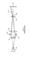
Fig. 1 is a diagram that schematically illustrates a prior art particle measurement instrument that employs a Fourier configuration; -
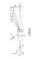
Fig. 2 is a perspective diagram of a prior art set of segmented detector arrays; -
Fig. 3 is a diagram that schematically illustrates a prior art instrument with low angle detection capabilities that uses a telephoto receiving lens configuration; -
Fig. 4 is a diagram that schematically illustrates a prior art instrument with coulter binocular optics; -
Fig. 5 is a diagram that schematically illustrates a prior art instrument with a reverse Fourier optics configuration; -
Fig. 6 is a perspective diagram of an illustrative particle size measurement instrument according to the invention that employs a diverging lens, -
Fig. 7 is a perspective diagram of an illustrative particle size measurement instrument according to the invention that employs a diverging mirror, -
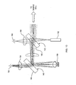
Fig. 8 is a perspective diagram of an illustrative particle size measurement instrument according to the invention that employs two wavelengths, -
Fig. 9 is an elevation diagram of an illustrative particle size measurement instrument according to the invention that employs two wavelengths, -
Fig. 10 is a diagram that generally illustrates the dual-wavelength approach presented in connection withFigs. 8 and9 ; and -
Fig. 11 is a diagram that illustrates the dual-wavelength approach presented in connection withFigs. 8 and9 with red sampling being carried out on a separate fold mirror. - Referring to
Figs. 6 and7 , one preferred embodiment of this invention involves a few added features, so as to make the instrument capable of measuring a large range of sample sizes whilst fitting into a small space. Red light from a laser diode is focused through a pinhole to remove aberrations and stray light from the source. It is then reflected into the instrument optical axis using aplanar mirror 70. A small but fixed proportion of light passes through the dichroic coating to a photodetector that is used to monitor or control the output of the laser source. - The main beam continues to expand until it reaches a focusing
lens system 72 beyond which it converges to a 1/ε2 diameter of 10mm at a flow cell 50mm away (74). The unscattered light continues to converge towards a focus until it hits a diverging lens 76 (Fig. 6 ) or a convex blue-pass dichroic mirror 108 (Fig. 7 ), cut down on one side to allow scattering angles of 3.7° or more to pass on one side towards an array ofphotodetectors 78 in the focal plane. The curved mirror is tilted in the plane perpendicular to theoptical axis 80 and the scatter detection to cause the reflected beam to be focused onto another focal plane detector. This mirror also reflects low angle scattered light onto the second detector array. Angles up to 1.7° can be detected above or below the focused beam, since the lens is truncated 5mm below its centre; angles up to 4° can be detected horizontally or upwards. Detection of angles between 4° and 7.6 must be downwards, to avoid the reflecting lens. Forward angles from 7.6° up to the cell limits can be detected at any orientation that is not obscured by the low angle focal plane detector. In the preferred embodiment, these larger forward angles are detected upwards with one array of sidescatter detectors and two or three more individually lensed detectors for the high angles, above and below the focused beam. - The effective focal length of this scheme is many times longer than the track length of the system. In the preferred embodiment, the numerical aperture of the beam focused on the detector is equivalent to a 900mm distance from cell to detector, and yet the whole optical train is shorter than 300mm.
- In one embodiment, distance of first surface of first lens from 658nm light source of 0.905 numerical aperture is 128.6mm The first lens is made of N-BK7 glass and has centre thickness of 5.0mm with radii of -102.3mm and -41.3mm respectively.
- The second lens is a cemented doublet placed with an air gap of 1.0mm from the first along the optical axis. The radius of curvature of the first surface is 115.2; the centreline thickness is 2.5mm and the material is N-LASF44 glass.
- The radius of curvature of the interface surface is 35.8mm. The second component of the doublet is N-BK7 glass and has a centre thickness of 8mm and an exit curvature of -93.8mm. These components form a module depicted as
item 72 ofFig.6A . The flow cell is 50mm away, has two N-BK7 windows 3mm thick and a water gap of 2.2mm, depicted as item 73 ofFig 6A . - The negative lens is made of N-LASF44 and is depicted as
item 76 ofFig.6A&B . Its first radius of curvature is -22.1mm and is 139.2mm away from the flow cell exit face. Its centre thickness is 2.5mm and its second face has a radius of curvature of 70.4mm. It is has a chordal cut 5mm to one side of the central axis. - The focal Plane detector array is 95.5mm from the exit face of the negative lens and is depicted as
item 78 ofFig.6A . It has a pinhole diameter of 0.1mm which is positioned to allow passage of the focused beam. The focal plane photodetector array has 38 photosensitive elements arranged predominantly on one side at distances from 0.08mm to 65.3mm with an expansion ratio between subsequent detectors of approximately 20%. - Sidescatter detectors placed close to the cut side of the expanding lens will be able to measure scattering angles as low as 4 degrees which is well within the range that can be measured by the outer detectors on the focal plane.
- Referring also to
Fig. 7 , an illustrative particle size measurement instrument according to the invention can also employ a divergingmirror 108. In this type of embodiment, low angle scattered light 110 is reflected back to a low-anglefocal plane detector 104. This arrangement allows the instrument to be even shorter. Mirror-based embodiments can be similar in other respects to lens-based embodiments. - Detectors can be placed so as to collect light in more than one scatter plane if there is a requirement to collect information on shape or orientation of particles.
- Referring to
Figs. 8 and9 , the scheme as described above can be further enhanced to allow measurement of more than one wavelength of light. In the preferred embodiment the main focused beam is nominally a 658nm from a laser diode, with a violet LED at 403nm. The light from the LED should be masked and conditioned to provide similar (or slightly smaller) numerical aperture to the red laser beam and can be reflected off or its owndichroic mirror red beam - The beam quality from the violet LED is generally not good enough to allow the transmission to be measured in the same way as for the red laser, so in the preferred embodiment, the reflective coating on the expanding lens is short-pass dichroic, to allow the violet light to pass through. The back surface of the expanding lens has a form so as to focus the light onto the centre of the detector plane.
- Other wavelength ranges could of course be used. The red source could be replaced with a near-infrared source, for example, and the violet source could be replaced with a blue or near-ultraviolet source. These substitutions can improve the dynamic range of the instrument, but they may also introduce additional problems, such as requiring more expensive optical materials. In some embodiments, a tunable or dual-wavelength source could be used.
- The sources need not be truly monochromatic, but they should preferably be spatially coherent in that they allow scatter from the larger particles to be differentiated from the focused beam. Laser diodes and LEDs are currently used, but other types of sources could be used, such as sodium lamps, mercury arc lamps, or other types of laser.
- Where multiple sources are used, they do not need to be coupled to the apparatus with the mirror arrangement shown in
Figs. 8 and9 . A single mirror could be shared, for example, with sources being turned on and off in succession. The sources could also be coupled into the system by placing one or more of them in alignment with the main optical axis of the system, although this could extend the length of the instrument. The sources could also be driven by known modulation methods. - Referring to
Figs. 10 and11 , the use of more than one source can also be applied to instruments that employ a conventional geometry. Providing two illumination sources that are coaxial allows the same detectors to be used to detect scattering at the different wavelengths. This is an improvement over some prior art systems that employ illumination beams at different angles, because the full range of the detectors can be exploited. - The use of at least one dichroic mirror is currently preferred, but other approaches for combining beams could also be employed, such as the use of polarized beams, polka dot mirrors, or semi-silvered mirrors. There is also an advantage of allowing red monitoring and enabling glass surfaces to be minimized in diffraction systems due to surface imperfections.
- The transmitted second wavelength (i.e. blue) light can either be measured by (i) some of the inner channels of the focal plane detector, or (ii) by a
separate detector 194, after being reflected by a second, red-passdichroic mirror 196 as shown inFig. 11 . An advantage of this approach is that it is an effective way of preventing reflections from the diode surface from getting back to the cell and contaminating the backscatter signals. In addition, where the blue source is an LED, which cannot be collimated as well as a laser, there can be some misalignment or slight angle between the two beams as they follow the same optical axis. - Where a blue laser is used for the second wavelength, the lasers can both be focused and aligned to the same point. A separate alignment mechanism would likely be needed to achieve this, such as through the use of a tip-tilt mechanism on the
blue sample mirror 170. In this case they should be coincident at the detector plane to within a few microns (equivalent to what is achieved for the red beam) and coincident at the cell to one or two millimetres or better. The design intent would be to have them perfectly coaxial. - The
dichroic mirror 196 close to the focal plane detector will prevent blue light from being collected on thefocal plane detector 190 but will not interfere with the red light. It is situated so as to allow larger angles (i.e. angles substantially above the collimation limitation of the blue light source) to get to the same detectors as intended to measure scattered red light. For example, in one embodiment there are 15 "sidescatter" detector elements situated to one side of the focal plane, and these will be able to collect scattering angles from 6 to 60 degrees for both wavelengths. The focal plane detector elements will gather only red light. The low angle blue light will be collected by theblue transmission monitor 194. - The instrument can also use a tilted
focal plane detector 190 without thedichroic mirror 196 andtransmission monitor 194. If this configuration is used it may be necessary to ensure that reflections from the focal plane are not reflected back to the cell, by means such as tilting the focal plane detector by a small angle. - The detectors can be organized as arrays of elements and/or as separate individual detectors. As is well known, it is preferable to organize them according to a substantially logarithmic progression, with some overlap in the angular ranges of the detectors.
- The sample can be presented to the instrument in a variety of ways, but the depth of the sample needs to be constrained to maintain instrument precision. To this end, a sample cell that has at least two walls at least generally normal to the optical axis is preferable. Further walls can also be provided to keep sample materials from contaminating the instrument.
- An instrument constructed according to this invention will generally need to maintain alignment and focus under a range of different environmental conditions and sample presentation arrangements. Rather than the conventional scheme of moving the focal plane photo-detector array, this optical scheme allows for realignment to be achieved by moving the expanding optic in the two axes perpendicular to the optical axis whilst keeping the focal plane array fixed relative to the other parts of the instrument. The amount of movement required of this lens is smaller (by a factor similar to the telescopic ratio) than the movement that would be required to move the focal plane array to correct the same misalignment. This allows the expected range of movements to be effected by simple micromanipulators rather than by more cumbersome mechanisms required to move the focal plane detection electronics.
- Focus correction can similarly be achieved by small movements of the expanding optic along the optical axis, with an equivalent beneficial reduction in the range and complexity of motion required. Movement of the optic can be performed before each measurement to optimize the pattern of light received by the detector elements for particular conditions. Any method that could be used to move the detector array can be used to move the expanding optic. Such methods can include the use of different types of actuators, such as piezoelectric actuators.
- Table 1 is a table of reference designators for the figures.
Table 1 Figure Ref. Description Fig. 1 10 1mW He/Ne Laser 12 Beam Expander 14 Parallel Monochromatic Light, such as from a collimating lens 16 Particle Field 18 -11° For 1 µm Particles 20 Fourier Transform Lens 22 Detector in Focal Plane of Lens Fig. 2 24 Segmented Photodetector Array Fig. 3 30 Laser Source 32 Collimating Lens 34 Sample 36 Cell Windows 38 Focusing Lens 40 Expanding Lens 42 Large Angle Scatter (Small Particles) 44 Low Angle Scatter (Large Particles) 46 Planar Detector Array Fig. 5 50 Laser 52 Backscatter Detector Fig. 6 70 Planar Mirror 72 Focusing Lens System 74 Flow Cell 76 Diverging Lens 78 Photodetector Array 80 Optical Axis Fig. 7 70 Blue-Pass Dichroic Mirror 72 Focusing Lens System 90 Diode Source Red Laser 92 Backscatter Detectors 94 Backscatter Detector 96 Flow Cell 98 Focal Plane Detector Low Angle 100 Sidescatter Detector 102 Low Numerical Aperture Beam 104 High Numerical Aperture Beam 106 Focal Plane Detector High Angle 108 Truncated Tilted Convex Mirror 110 Low Angle Scattered Light Fig. 8 120 Violet Dichroic Mirror 122 Red Dichroic Mirror Fig. 9 130 Violet Dichroic Mirror 132 Red Dichroic Mirror Fig. 10 140 Blue Sample Mirror 142 Dichroic Mirror 144 Antireflective Coating (blue) 146 Antireflective Coating (red) 150 Blue or Violet LED 152 Laser (red) 154 Light Gathering Lens 156 Detector 164 Light Gathering Lens 166 Detector Fig. 11 170 Blue Sample Mirror 172 Red-Pass Dichroic Mirror 174 Light Gathering Lens 176 Red Sample Mirror 178 Light Gathering Lens 184 Sample Cell 186 Antireflective Coating 188 Antireflective Coating 190 Focal Plane Detector 192 Main Focussing Lens 194 Blue Transmission Monitor 196 Dichroic (Reflects Blue Light) - The present invention has now been described in connection with a number of specific embodiments thereof. However, numerous modifications which are contemplated as falling within the scope of the present invention should now be apparent to those skilled in the art. It is therefore intended that the scope of the present invention be limited only by the scope of the claims appended hereto. In addition, the order of presentation of the claims should not be construed to limit the scope of any particular term in the claims.
Claims (12)
- A particle characterization instrument, comprising:a first spatially coherent light source (90) having a beam output aligned with an optical axis (80),a focusing optic (72) positioned along the optical axis (80) after the light source (90) to produce a converging beam,a sample cell (96) positioned along the optical axis (80) after the focusing optic (72) and in the path of the converging beam,a first detector (98, 78) positioned outside of the optical axis to receive scattered light (110) within a first range of scattering angles from the diverging optic (108), anda second detector (106) positioned outside of the optical axis to receive scattered light within a second range of scattering angles directly from the sample cell (96) characterised in that the instrument comprises a diverging optic (108, 76) positioned along the optical axis after the sample cell (96) and in the path of the converging beam.
- The instrument of claim 1 further including a second light source having a wavelength that is different from a wavelength of the first light source (90), and
optionally or preferably wherein the wavelength of the first source is longer than the wavelength of the second source, and wherein the different wavelengths provide an increased dynamic range to the instrument, and
further optionally or preferably wherein the first wavelength is a wavelength in the spectral vicinity of red and the second wavelength is a wavelength in the spectral vicinity of violet. - The instrument of claim 1 wherein the diverging optic is a lens (76) having at least one concave refractive surface.
- The instrument of claim 3 further including a second light source having a wavelength that is different from a wavelength of the first light source, and
optionally or preferably wherein the wavelength of the first source (90) is longer than the wavelength of the second source, and wherein the different wavelengths provide an increased dynamic range to the instrument. - The instrument of claim 3 wherein the concave refractive surface is a refractive portion of a circular concave surface and wherein a portion of the circular concave surface is truncated to allow scattered light within the second range of scattering angles to pass the diverging optic, and optionally or preferably including a third detector positioned outside the optical axis to receive further scattered light within a third range of scattering angles that are sufficiently large to cause it to pass the diverging optic, and
further optionally or preferably including a second light source having a wavelength that is different from a wavelength of the first light source. - The instrument of claim 1 wherein the diverging optic includes a convex reflective surface (108).
- The instrument of claim 6 wherein the convex reflecting surface is a reflecting portion of a circular convex surface (108) and wherein a portion of the circular convex surface is truncated to allow scattered light within the second range of scattering angles to pass the diverging optic, and
optionally or preferably including a third detector (100) positioned outside the optical axis to receive further scattered light within a third range of scattering angles that are sufficiently large to cause it to pass the diverging optic. - The instrument of claim 6 further including a second light source having a wavelength that is different from a wavelength of the first light source, wherein the diverging optic (108) is dichroic to reflect light from the first source while allowing light from the second source to pass through, and further including a third detector behind the divergent optic to receive scattered light from the second source, and optionally or preferably further including a fourth detector positioned outside the optical axis to receive further scattered light from the second light source within a third range of scattering angles that are sufficiently large to pass the diverging optic.
- The instrument of claim 1 further including a mirror between the light source and the focusing optic that bends the optical axis, and optionally or preferably further including a second light source having a wavelength that is different from a wavelength of the first light source, the mirror being dichroic to reflect light from the first source while allowing light from the second source to pass through, and
further optionally or preferably wherein the first wavelength is a red wavelength and the second wavelength is a violet wavelength. - The instrument of claim 1 wherein the source (90) is a solid-state source, or further including at least one backscatter detector (92) positioned outside of the optical axis behind the sample cell (96), or further including a second light source having a wavelength that is different from a wavelength of the first light source, or further including at least one actuator operative to move the diverging optic, or wherein the actuator is operative to move the diverging optic along its optical axis to adjust focus, or wherein the actuator is operative to move the diverging optic perpendicular to its optical axis to adjust alignment.
- The instrument of claim 1 wherein the first and second detectors (98, 106) are multi-element detectors.
- A particle characterization method, comprising:focusing a beam of spatially coherent light to produce a converging beam of light, causing the converging beam of light to interact with a plurality of particles to produce scattered light, causing light scattered within a first range of scattering angles to interact with a diverging optic (108, 76) and then detecting said scattered light, and directly detecting light scattered within a second range of scattering angles.
Priority Applications (1)
| Application Number | Priority Date | Filing Date | Title |
|---|---|---|---|
| EP12176047.4A EP2522982B1 (en) | 2007-08-15 | 2008-08-15 | Broad-Range Spectrometer |
Applications Claiming Priority (2)
| Application Number | Priority Date | Filing Date | Title |
|---|---|---|---|
| US96482807P | 2007-08-15 | 2007-08-15 | |
| PCT/IB2008/003743 WO2009063322A2 (en) | 2007-08-15 | 2008-08-15 | Broad-range spectrometer |
Related Child Applications (2)
| Application Number | Title | Priority Date | Filing Date |
|---|---|---|---|
| EP12176047.4A Division EP2522982B1 (en) | 2007-08-15 | 2008-08-15 | Broad-Range Spectrometer |
| EP12176047.4 Division-Into | 2012-07-12 |
Publications (2)
| Publication Number | Publication Date |
|---|---|
| EP2181317A2 EP2181317A2 (en) | 2010-05-05 |
| EP2181317B1 true EP2181317B1 (en) | 2012-12-05 |
Family
ID=40623397
Family Applications (2)
| Application Number | Title | Priority Date | Filing Date |
|---|---|---|---|
| EP08849794A Active EP2181317B1 (en) | 2007-08-15 | 2008-08-15 | Broad-range spectrometer |
| EP12176047.4A Active EP2522982B1 (en) | 2007-08-15 | 2008-08-15 | Broad-Range Spectrometer |
Family Applications After (1)
| Application Number | Title | Priority Date | Filing Date |
|---|---|---|---|
| EP12176047.4A Active EP2522982B1 (en) | 2007-08-15 | 2008-08-15 | Broad-Range Spectrometer |
Country Status (4)
| Country | Link |
|---|---|
| US (1) | US7869038B2 (en) |
| EP (2) | EP2181317B1 (en) |
| JP (2) | JP5546454B2 (en) |
| WO (1) | WO2009063322A2 (en) |
Families Citing this family (16)
| Publication number | Priority date | Publication date | Assignee | Title |
|---|---|---|---|---|
| JP5822534B2 (en) * | 2011-05-13 | 2015-11-24 | 株式会社日立ハイテクノロジーズ | Automatic analyzer |
| GB2494735B (en) * | 2011-09-14 | 2017-10-25 | Malvern Instr Ltd | Apparatus for measuring particle-size distribution by light scattering |
| GB2494733A (en) * | 2011-09-14 | 2013-03-20 | Malvern Instr Ltd | Measuring particle size distribution by light scattering |
| RU2616653C2 (en) * | 2012-06-05 | 2017-04-18 | Хайпермед Имэджинг, Инк. | Methods and device for coaxial image forming with multiple wavelengths |
| CN106461462B (en) | 2014-03-21 | 2019-03-26 | 海佩尔梅德影像有限公司 | compact light sensor |
| US9655519B2 (en) | 2014-03-21 | 2017-05-23 | Hypermed Imaging, Inc. | Systems and methods for performing an imaging test under constrained conditions |
| WO2016063364A1 (en) * | 2014-10-22 | 2016-04-28 | 株式会社日立ハイテクノロジーズ | Cytometric mechanism, cell culture device comprising same, and cytometric method |
| CN106092972A (en) * | 2015-04-27 | 2016-11-09 | 松下知识产权经营株式会社 | Optical sensing means |
| RU2600516C1 (en) * | 2015-07-06 | 2016-10-20 | Федеральное государственное бюджетное образовательное учреждение высшего образования "Тверской государственный университет" | Infrared spectroscopic method of determining anisotropy of filler particles in the volume of the polymer matrix |
| RU2592750C1 (en) * | 2015-07-06 | 2016-07-27 | Федеральное государственное бюджетное образовательное учреждение высшего образования "Тверской государственный университет" | Infrared spectroscopic method of determining orientation anisometric particles of filler in volume of polymer matrix |
| CN105259143B (en) * | 2015-10-15 | 2019-03-29 | 南京医科大学 | A Rapid Microbial Detection Device Based on Mie Scattering and Spatial Light Modulator |
| WO2017201093A1 (en) | 2016-05-17 | 2017-11-23 | Hypermed Imaging, Inc. | Hyperspectral imager coupled with indicator molecule tracking |
| US11086211B2 (en) * | 2017-11-08 | 2021-08-10 | Taiwan Semiconductor Manufacturing Company, Ltd. | Masks and methods of forming the same |
| EP3521810B1 (en) * | 2018-01-31 | 2019-11-27 | SICK Engineering GmbH | Analyser for the determination of fine dust |
| KR102749855B1 (en) | 2019-07-24 | 2025-01-02 | 삼성전자주식회사 | Particulate matter measurement apparatus and method |
| CN120404507B (en) * | 2025-04-18 | 2026-01-02 | 中国人民解放军国防科技大学 | Wind snow blowing particle self-adaptive imaging measurement system and method based on double-view-field fusion |
Family Cites Families (27)
| Publication number | Priority date | Publication date | Assignee | Title |
|---|---|---|---|---|
| FR2445961A1 (en) * | 1979-01-02 | 1980-08-01 | Coulter Electronics | METHOD AND DEVICE WITH FLOW CHAMBER READITING RADIANT ENERGY |
| JPS59160741A (en) | 1983-03-03 | 1984-09-11 | Toshiba Corp | Measuring device of grain size |
| US4545677A (en) * | 1984-03-05 | 1985-10-08 | Becton, Dickinson And Company | Prismatic beam expander for light beam shaping in a flow cytometry apparatus |
| EP0207176B1 (en) * | 1985-06-07 | 1990-01-17 | Fritsch GmbH | Device for determining the size of particles |
| US4871251A (en) * | 1987-04-27 | 1989-10-03 | Preikschat F K | Apparatus and method for particle analysis |
| JP2626009B2 (en) * | 1988-12-26 | 1997-07-02 | 株式会社島津製作所 | Particle size distribution analyzer |
| US4953978A (en) * | 1989-03-03 | 1990-09-04 | Coulter Electronics Of New England, Inc. | Particle size analysis utilizing polarization intensity differential scattering |
| US5056918A (en) * | 1989-03-03 | 1991-10-15 | Coulter Electronics Of New England, Inc. | Method and apparatus for particle size analysis |
| US5104221A (en) * | 1989-03-03 | 1992-04-14 | Coulter Electronics Of New England, Inc. | Particle size analysis utilizing polarization intensity differential scattering |
| JPH081482Y2 (en) * | 1990-11-17 | 1996-01-17 | 株式会社堀場製作所 | Particle size distribution measuring device |
| IL113805A0 (en) * | 1994-05-23 | 1995-08-31 | Coulter Corp | Detection of reticulocytes |
| JP4323571B2 (en) * | 1997-01-31 | 2009-09-02 | エックスワイ, インコーポレイテッド | Optical device |
| US5999250A (en) * | 1997-03-17 | 1999-12-07 | Tsi Corporation | System for detecting fluorescing components in aerosols |
| US6034760A (en) * | 1997-10-21 | 2000-03-07 | Flight Safety Technologies, Inc. | Method of detecting weather conditions in the atmosphere |
| GB9818351D0 (en) * | 1998-08-22 | 1998-10-14 | Malvern Instr Ltd | Improvements relating to the measurement of particle size distribution |
| GB9818348D0 (en) * | 1998-08-22 | 1998-10-14 | Malvern Instr Ltd | Improvements relating to the measurement of particle size distribution |
| DE19948587A1 (en) * | 1999-10-08 | 2001-04-12 | Dade Behring Marburg Gmbh | Spectrophotometric and nephelometric detection unit |
| JP2001116692A (en) * | 1999-10-18 | 2001-04-27 | Nittan Co Ltd | Smoke sensor and particulate size measuring device and particulate kind discriminating device |
| JP3771417B2 (en) * | 2000-03-21 | 2006-04-26 | 独立行政法人科学技術振興機構 | Fine particle measurement method and apparatus |
| JP2001330551A (en) * | 2000-05-24 | 2001-11-30 | Shimadzu Corp | Particle measurement device |
| JP3412606B2 (en) * | 2000-08-04 | 2003-06-03 | 株式会社島津製作所 | Laser diffraction / scattering particle size distribution analyzer |
| US6618140B2 (en) * | 2001-06-18 | 2003-09-09 | Amnis Corporation | Spectral deconvolution of fluorescent markers |
| DE10317669B4 (en) * | 2003-04-17 | 2017-03-09 | Leica Microsystems Cms Gmbh | Method for separating detection channels of a microscopic system |
| JP4426402B2 (en) * | 2004-08-31 | 2010-03-03 | 株式会社堀場製作所 | Particle size distribution measuring device |
| JP4756948B2 (en) * | 2005-08-08 | 2011-08-24 | ベイバイオサイエンス株式会社 | Flow cytometer and flow cytometry method |
| US7554661B2 (en) * | 2005-09-19 | 2009-06-30 | Jmar Technologies, Inc. | Systems and methods for detection and classification of waterborne particles using a multiple angle light scattering (MALS) instrument |
| DE102006019138B4 (en) | 2006-04-21 | 2021-06-10 | Fritsch Gmbh | Particle analyzer with magnification range |
-
2008
- 2008-08-15 WO PCT/IB2008/003743 patent/WO2009063322A2/en not_active Ceased
- 2008-08-15 EP EP08849794A patent/EP2181317B1/en active Active
- 2008-08-15 JP JP2010520648A patent/JP5546454B2/en active Active
- 2008-08-15 US US12/228,871 patent/US7869038B2/en active Active
- 2008-08-15 EP EP12176047.4A patent/EP2522982B1/en active Active
-
2013
- 2013-04-22 JP JP2013089381A patent/JP5705261B2/en active Active
Also Published As
| Publication number | Publication date |
|---|---|
| WO2009063322A2 (en) | 2009-05-22 |
| EP2522982A3 (en) | 2012-12-26 |
| JP2010537165A (en) | 2010-12-02 |
| EP2181317A2 (en) | 2010-05-05 |
| US7869038B2 (en) | 2011-01-11 |
| JP5705261B2 (en) | 2015-04-22 |
| EP2522982A2 (en) | 2012-11-14 |
| WO2009063322A3 (en) | 2010-01-28 |
| EP2522982B1 (en) | 2015-09-16 |
| US20090122313A1 (en) | 2009-05-14 |
| JP2013174604A (en) | 2013-09-05 |
| JP5546454B2 (en) | 2014-07-09 |
Similar Documents
| Publication | Publication Date | Title |
|---|---|---|
| US7869038B2 (en) | Broad-range spectrometer | |
| US20230176191A1 (en) | 2D SCANNING HIGH PRECISION LiDAR USING COMBINATION OF ROTATING CONCAVE MIRROR AND BEAM STEERING DEVICES | |
| US5056918A (en) | Method and apparatus for particle size analysis | |
| EP3066452B1 (en) | Improvements relating to particle characterisation | |
| JP7607669B6 (en) | Apparatus and method for reducing interference in an optical spectroscopy probe having a collimated sample beam - Patents.com | |
| US20020057432A1 (en) | Multipass cavity for illumination and excitation of moving objects | |
| US20210263306A1 (en) | Optical spectroscopy probe configurations for focusing light to a portion of a sample | |
| JPH0258585B2 (en) | ||
| US3966324A (en) | Laser doppler anemometer | |
| JP2022512143A (en) | Equipment and methods for light beam scanning microspectroscopy | |
| EP2869057A1 (en) | Improvements Relating to Particle Characterisation | |
| EP2869056B1 (en) | Improvements relating to particle characterisation | |
| US7248364B2 (en) | Apparatus and method for optical characterization of a sample over a broadband of wavelengths with a small spot size | |
| CN110109262B (en) | Coaxiality debugging system and method for light source switching multiplexing unit | |
| CN119414365B (en) | Scanning module and laser radar | |
| CN222704829U (en) | Autocollimator image-finding device and imaging device | |
| HK40084052A (en) | Apparatus and method for reducing interference in an optical spectroscopy probe having a collimated sample beam | |
| CN120232867A (en) | Multi-wavelength reflective Raman probe and Raman spectrum detection device | |
| SU1679215A1 (en) | Multichannel spectrofotometer |
Legal Events
| Date | Code | Title | Description |
|---|---|---|---|
| PUAI | Public reference made under article 153(3) epc to a published international application that has entered the european phase |
Free format text: ORIGINAL CODE: 0009012 |
|
| 17P | Request for examination filed |
Effective date: 20100219 |
|
| AK | Designated contracting states |
Kind code of ref document: A2 Designated state(s): AT BE BG CH CY CZ DE DK EE ES FI FR GB GR HR HU IE IS IT LI LT LU LV MC MT NL NO PL PT RO SE SI SK TR |
|
| 17Q | First examination report despatched |
Effective date: 20100727 |
|
| DAX | Request for extension of the european patent (deleted) | ||
| GRAP | Despatch of communication of intention to grant a patent |
Free format text: ORIGINAL CODE: EPIDOSNIGR1 |
|
| RIC1 | Information provided on ipc code assigned before grant |
Ipc: G01N 15/02 20060101AFI20120615BHEP Ipc: G01N 15/14 20060101ALI20120615BHEP Ipc: G01N 21/51 20060101ALI20120615BHEP |
|
| GRAS | Grant fee paid |
Free format text: ORIGINAL CODE: EPIDOSNIGR3 |
|
| GRAA | (expected) grant |
Free format text: ORIGINAL CODE: 0009210 |
|
| AK | Designated contracting states |
Kind code of ref document: B1 Designated state(s): AT BE BG CH CY CZ DE DK EE ES FI FR GB GR HR HU IE IS IT LI LT LU LV MC MT NL NO PL PT RO SE SI SK TR |
|
| REG | Reference to a national code |
Ref country code: GB Ref legal event code: FG4D |
|
| REG | Reference to a national code |
Ref country code: CH Ref legal event code: EP |
|
| REG | Reference to a national code |
Ref country code: AT Ref legal event code: REF Ref document number: 587525 Country of ref document: AT Kind code of ref document: T Effective date: 20121215 |
|
| REG | Reference to a national code |
Ref country code: IE Ref legal event code: FG4D |
|
| REG | Reference to a national code |
Ref country code: DE Ref legal event code: R096 Ref document number: 602008020683 Country of ref document: DE Effective date: 20130124 |
|
| REG | Reference to a national code |
Ref country code: AT Ref legal event code: MK05 Ref document number: 587525 Country of ref document: AT Kind code of ref document: T Effective date: 20121205 |
|
| PG25 | Lapsed in a contracting state [announced via postgrant information from national office to epo] |
Ref country code: LT Free format text: LAPSE BECAUSE OF FAILURE TO SUBMIT A TRANSLATION OF THE DESCRIPTION OR TO PAY THE FEE WITHIN THE PRESCRIBED TIME-LIMIT Effective date: 20121205 Ref country code: NO Free format text: LAPSE BECAUSE OF FAILURE TO SUBMIT A TRANSLATION OF THE DESCRIPTION OR TO PAY THE FEE WITHIN THE PRESCRIBED TIME-LIMIT Effective date: 20130305 Ref country code: FI Free format text: LAPSE BECAUSE OF FAILURE TO SUBMIT A TRANSLATION OF THE DESCRIPTION OR TO PAY THE FEE WITHIN THE PRESCRIBED TIME-LIMIT Effective date: 20121205 Ref country code: SE Free format text: LAPSE BECAUSE OF FAILURE TO SUBMIT A TRANSLATION OF THE DESCRIPTION OR TO PAY THE FEE WITHIN THE PRESCRIBED TIME-LIMIT Effective date: 20121205 Ref country code: HR Free format text: LAPSE BECAUSE OF FAILURE TO SUBMIT A TRANSLATION OF THE DESCRIPTION OR TO PAY THE FEE WITHIN THE PRESCRIBED TIME-LIMIT Effective date: 20121205 Ref country code: ES Free format text: LAPSE BECAUSE OF FAILURE TO SUBMIT A TRANSLATION OF THE DESCRIPTION OR TO PAY THE FEE WITHIN THE PRESCRIBED TIME-LIMIT Effective date: 20130316 |
|
| REG | Reference to a national code |
Ref country code: NL Ref legal event code: VDEP Effective date: 20121205 |
|
| REG | Reference to a national code |
Ref country code: LT Ref legal event code: MG4D |
|
| PG25 | Lapsed in a contracting state [announced via postgrant information from national office to epo] |
Ref country code: SI Free format text: LAPSE BECAUSE OF FAILURE TO SUBMIT A TRANSLATION OF THE DESCRIPTION OR TO PAY THE FEE WITHIN THE PRESCRIBED TIME-LIMIT Effective date: 20121205 Ref country code: GR Free format text: LAPSE BECAUSE OF FAILURE TO SUBMIT A TRANSLATION OF THE DESCRIPTION OR TO PAY THE FEE WITHIN THE PRESCRIBED TIME-LIMIT Effective date: 20130306 Ref country code: PL Free format text: LAPSE BECAUSE OF FAILURE TO SUBMIT A TRANSLATION OF THE DESCRIPTION OR TO PAY THE FEE WITHIN THE PRESCRIBED TIME-LIMIT Effective date: 20121205 Ref country code: LV Free format text: LAPSE BECAUSE OF FAILURE TO SUBMIT A TRANSLATION OF THE DESCRIPTION OR TO PAY THE FEE WITHIN THE PRESCRIBED TIME-LIMIT Effective date: 20121205 |
|
| PG25 | Lapsed in a contracting state [announced via postgrant information from national office to epo] |
Ref country code: AT Free format text: LAPSE BECAUSE OF FAILURE TO SUBMIT A TRANSLATION OF THE DESCRIPTION OR TO PAY THE FEE WITHIN THE PRESCRIBED TIME-LIMIT Effective date: 20121205 |
|
| PG25 | Lapsed in a contracting state [announced via postgrant information from national office to epo] |
Ref country code: EE Free format text: LAPSE BECAUSE OF FAILURE TO SUBMIT A TRANSLATION OF THE DESCRIPTION OR TO PAY THE FEE WITHIN THE PRESCRIBED TIME-LIMIT Effective date: 20121205 Ref country code: BG Free format text: LAPSE BECAUSE OF FAILURE TO SUBMIT A TRANSLATION OF THE DESCRIPTION OR TO PAY THE FEE WITHIN THE PRESCRIBED TIME-LIMIT Effective date: 20130305 Ref country code: BE Free format text: LAPSE BECAUSE OF FAILURE TO SUBMIT A TRANSLATION OF THE DESCRIPTION OR TO PAY THE FEE WITHIN THE PRESCRIBED TIME-LIMIT Effective date: 20121205 Ref country code: SK Free format text: LAPSE BECAUSE OF FAILURE TO SUBMIT A TRANSLATION OF THE DESCRIPTION OR TO PAY THE FEE WITHIN THE PRESCRIBED TIME-LIMIT Effective date: 20121205 Ref country code: CZ Free format text: LAPSE BECAUSE OF FAILURE TO SUBMIT A TRANSLATION OF THE DESCRIPTION OR TO PAY THE FEE WITHIN THE PRESCRIBED TIME-LIMIT Effective date: 20121205 Ref country code: IS Free format text: LAPSE BECAUSE OF FAILURE TO SUBMIT A TRANSLATION OF THE DESCRIPTION OR TO PAY THE FEE WITHIN THE PRESCRIBED TIME-LIMIT Effective date: 20130405 |
|
| PG25 | Lapsed in a contracting state [announced via postgrant information from national office to epo] |
Ref country code: PT Free format text: LAPSE BECAUSE OF FAILURE TO SUBMIT A TRANSLATION OF THE DESCRIPTION OR TO PAY THE FEE WITHIN THE PRESCRIBED TIME-LIMIT Effective date: 20130405 Ref country code: RO Free format text: LAPSE BECAUSE OF FAILURE TO SUBMIT A TRANSLATION OF THE DESCRIPTION OR TO PAY THE FEE WITHIN THE PRESCRIBED TIME-LIMIT Effective date: 20121205 Ref country code: NL Free format text: LAPSE BECAUSE OF FAILURE TO SUBMIT A TRANSLATION OF THE DESCRIPTION OR TO PAY THE FEE WITHIN THE PRESCRIBED TIME-LIMIT Effective date: 20121205 |
|
| PLBE | No opposition filed within time limit |
Free format text: ORIGINAL CODE: 0009261 |
|
| STAA | Information on the status of an ep patent application or granted ep patent |
Free format text: STATUS: NO OPPOSITION FILED WITHIN TIME LIMIT |
|
| PG25 | Lapsed in a contracting state [announced via postgrant information from national office to epo] |
Ref country code: DK Free format text: LAPSE BECAUSE OF FAILURE TO SUBMIT A TRANSLATION OF THE DESCRIPTION OR TO PAY THE FEE WITHIN THE PRESCRIBED TIME-LIMIT Effective date: 20121205 |
|
| 26N | No opposition filed |
Effective date: 20130906 |
|
| PG25 | Lapsed in a contracting state [announced via postgrant information from national office to epo] |
Ref country code: CY Free format text: LAPSE BECAUSE OF FAILURE TO SUBMIT A TRANSLATION OF THE DESCRIPTION OR TO PAY THE FEE WITHIN THE PRESCRIBED TIME-LIMIT Effective date: 20121205 |
|
| PG25 | Lapsed in a contracting state [announced via postgrant information from national office to epo] |
Ref country code: IT Free format text: LAPSE BECAUSE OF FAILURE TO SUBMIT A TRANSLATION OF THE DESCRIPTION OR TO PAY THE FEE WITHIN THE PRESCRIBED TIME-LIMIT Effective date: 20121205 |
|
| REG | Reference to a national code |
Ref country code: DE Ref legal event code: R097 Ref document number: 602008020683 Country of ref document: DE Effective date: 20130906 |
|
| REG | Reference to a national code |
Ref country code: CH Ref legal event code: PL |
|
| PG25 | Lapsed in a contracting state [announced via postgrant information from national office to epo] |
Ref country code: LI Free format text: LAPSE BECAUSE OF NON-PAYMENT OF DUE FEES Effective date: 20130831 Ref country code: MC Free format text: LAPSE BECAUSE OF FAILURE TO SUBMIT A TRANSLATION OF THE DESCRIPTION OR TO PAY THE FEE WITHIN THE PRESCRIBED TIME-LIMIT Effective date: 20121205 Ref country code: CH Free format text: LAPSE BECAUSE OF NON-PAYMENT OF DUE FEES Effective date: 20130831 |
|
| REG | Reference to a national code |
Ref country code: IE Ref legal event code: MM4A |
|
| PG25 | Lapsed in a contracting state [announced via postgrant information from national office to epo] |
Ref country code: IE Free format text: LAPSE BECAUSE OF NON-PAYMENT OF DUE FEES Effective date: 20130815 |
|
| PG25 | Lapsed in a contracting state [announced via postgrant information from national office to epo] |
Ref country code: MT Free format text: LAPSE BECAUSE OF FAILURE TO SUBMIT A TRANSLATION OF THE DESCRIPTION OR TO PAY THE FEE WITHIN THE PRESCRIBED TIME-LIMIT Effective date: 20121205 Ref country code: TR Free format text: LAPSE BECAUSE OF FAILURE TO SUBMIT A TRANSLATION OF THE DESCRIPTION OR TO PAY THE FEE WITHIN THE PRESCRIBED TIME-LIMIT Effective date: 20121205 |
|
| PG25 | Lapsed in a contracting state [announced via postgrant information from national office to epo] |
Ref country code: HU Free format text: LAPSE BECAUSE OF FAILURE TO SUBMIT A TRANSLATION OF THE DESCRIPTION OR TO PAY THE FEE WITHIN THE PRESCRIBED TIME-LIMIT; INVALID AB INITIO Effective date: 20080815 Ref country code: LU Free format text: LAPSE BECAUSE OF NON-PAYMENT OF DUE FEES Effective date: 20130815 |
|
| REG | Reference to a national code |
Ref country code: FR Ref legal event code: PLFP Year of fee payment: 9 |
|
| REG | Reference to a national code |
Ref country code: FR Ref legal event code: PLFP Year of fee payment: 10 |
|
| REG | Reference to a national code |
Ref country code: FR Ref legal event code: PLFP Year of fee payment: 11 |
|
| P01 | Opt-out of the competence of the unified patent court (upc) registered |
Effective date: 20230727 |
|
| PGFP | Annual fee paid to national office [announced via postgrant information from national office to epo] |
Ref country code: DE Payment date: 20250724 Year of fee payment: 18 |
|
| PGFP | Annual fee paid to national office [announced via postgrant information from national office to epo] |
Ref country code: GB Payment date: 20250724 Year of fee payment: 18 |
|
| PGFP | Annual fee paid to national office [announced via postgrant information from national office to epo] |
Ref country code: FR Payment date: 20250725 Year of fee payment: 18 |