EP2180720A1 - Apparatus for preventing leakage of a weak signal from a speaker - Google Patents
Apparatus for preventing leakage of a weak signal from a speaker Download PDFInfo
- Publication number
- EP2180720A1 EP2180720A1 EP09166026A EP09166026A EP2180720A1 EP 2180720 A1 EP2180720 A1 EP 2180720A1 EP 09166026 A EP09166026 A EP 09166026A EP 09166026 A EP09166026 A EP 09166026A EP 2180720 A1 EP2180720 A1 EP 2180720A1
- Authority
- EP
- European Patent Office
- Prior art keywords
- speaker
- threshold element
- signal
- bidirectional threshold
- weak signal
- Prior art date
- Legal status (The legal status is an assumption and is not a legal conclusion. Google has not performed a legal analysis and makes no representation as to the accuracy of the status listed.)
- Granted
Links
Images




Classifications
-
- H—ELECTRICITY
- H03—ELECTRONIC CIRCUITRY
- H03G—CONTROL OF AMPLIFICATION
- H03G3/00—Gain control in amplifiers or frequency changers
- H03G3/20—Automatic control
- H03G3/30—Automatic control in amplifiers having semiconductor devices
- H03G3/34—Muting amplifier when no signal is present
-
- H—ELECTRICITY
- H04—ELECTRIC COMMUNICATION TECHNIQUE
- H04R—LOUDSPEAKERS, MICROPHONES, GRAMOPHONE PICK-UPS OR LIKE ACOUSTIC ELECTROMECHANICAL TRANSDUCERS; ELECTRIC HEARING AIDS; PUBLIC ADDRESS SYSTEMS
- H04R3/00—Circuits for transducers
Definitions
- the present invention relates to an apparatus for preventing leakage of a weak signal from a speaker, and more particularly, to an apparatus for preventing leakage of a weak signal from a speaker, which passes a normal speaker drive signal coming from an audio system through speaker signal lines and blocks a weak signal generated by the sounds around the speaker.
- FIGS. 1A and 1B are schematic diagrams showing structures of a speaker 100a and a microphone 100b respectively
- FIG. 1C is a schematic diagram showing a structure of a broadcast speaker for announcement 100c.
- the conventional speaker 100a has a structure including a voice coil 120a surrounding a permanent magnet 110a and a diaphragm 130a attached to the voice coil 120a.
- a voice coil 120a surrounding a permanent magnet 110a
- a diaphragm 130a attached to the voice coil 120a.
- the microphone 100b has the similar structure as the speaker 100a.
- a current flows in the voice coil 120b according to electromagnetic induction.
- the current is transmitted to a signal receiver D2 through the microphone signal lines 140b.
- the speaker 100a have basically the similar structure as the microphone 100b, so a current may be generated by speaker-around sounds and flows in the voice coil 120a of the speaker 100a, as in the microphone 100b.
- the conversation around the speaker may be eavesdropped.
- conversations around all speakers connected to the common signal lines may be eavesdropped simultaneously if a person branches off the common signal lines.
- the broadcast speaker 100c generally includes a transformer 160 which is used to minimize the transmission power loss but may make eavesdropping easy because it amplifies a weak signal of the voice coil 120a.
- the present invention provides an apparatus for preventing a weak signal generated by the sounds around the speaker from being leaked through speaker signal lines.
- an apparatus for preventing leakage of a weak signal from a speaker including: a bidirectional threshold element configured to conduct only when a voltage difference between both sides is larger than a predetermined value, wherein the bidirectional threshold element passes a speaker drive signal coming through speaker signal lines and blocks a weak signal coming from a voice coil of the speaker.
- the bidirectional threshold element may include two parallel diodes connected in an opposite direction or two serial Zener diodes connected in an opposite direction.
- the bidirectional threshold element may include at least one varistor.
- the apparatus may further include: a low pass filter for blocking a noise or an abnormal signal whose frequency is above the audible frequency.
- the low pass filter may include inductors and capacitors.
- the apparatus may further include: a high pass filter for bypassing a noise or an abnormal signal whose frequency is above the audible frequency to another path.
- the high pass filter may include capacitors.
- the apparatus may further include: a limiter for limiting a voltage difference between the speaker signal lines to be less than a predetermined value.
- the limiter may include a varistor.
- FIGS. 1A and 1B are schematic diagrams showing structures of a speaker and a microphone
- FIG. 1C is a schematic diagram showing a structure of a broadcast speaker for announcement
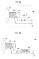
- FIGS. 2A and 2B are schematic diagrams of a speaker which includes a device for preventing leakage of a weak signal according to an exemplary embodiment of the present invention
- FIGS. 3A and 3B are schematic diagrams of a speaker which further includes a transformer, together with the device for preventing leakage of a weak signal according to an exemplary embodiment of the present invention
- FIG. 4A shows an example in which a Low Pass Filter (LPF) and a limiter are connected to a bidirectional threshold element according to an exemplary embodiment of the present invention
- FIG. 4B shows an example in which the LPF of FIG. 4A is implemented with two inductors and one capacitor and the limiter of FIG. 4A is implemented with a varistor;
- LPF Low Pass Filter
- FIG. 5A shows an example in which a High Pass Filter (HPF) and a limiter are connected to a bidirectional threshold element according to an exemplary embodiment of the present invention
- FIG. 5B shows an example in which the HPF of FIG. 5A is implemented with a capacitor and the limiter of FIG. 5A is implemented with a varistor;
- HPF High Pass Filter
- FIG. 6 is a measured graph of voltage-current characteristics of the bidirectional threshold element 240a according to an exemplary embodiment of the present invention.
- FIG. 7A shows a test setup for measuring a voltage amplitude of a weak signal generated in the conventional speaker as changing the input sound intensity to the speaker
- FIG. 7B is a graph showing a maximum voltage amplitude of a weak signal measured at the front (channel 1) and rear (channel 2) of a transformer 160 according to the input sound intensity to the conventional speaker in FIG. 7A ;
- FIG. 8A shows a test setup for measuring a voltage amplitude of a normal speaker drive signal coming from an audio amplifier (AMP) as changing the output sound intensity measured by a sound level meter (D4) 50 cm apart from the broadcast speaker for announcement, 100C;
- FIG. 8B is a graph showing a maximum voltage amplitude of a speaker drive signal measured at the front (channel 1) and rear (channel 2) of a transformer according to the output sound intensity from the speaker in FIG. 8A ;
- FIG. 9 shows a test setup for checking the effect of the signal leakage prevention device 240 according to an exemplary embodiment of the present invention.
- FIG. 10 shows a test setup for checking whether the speaker, which includes the signal leakage prevention device 240 according to an exemplary embodiment of the present invention, normally operates.
- FIGS. 2A and 2B are schematic diagrams of a speaker 200 which includes a device 240 for preventing leakage of a weak signal according to an exemplary embodiment of the present invention.
- the speaker 200 includes a permanent magnet 210, a voice coil 220 surrounding the permanent magnet 210, a diaphragm 230 connected to one side of the voice coil 220, and the device 240 for preventing leakage of a weak signal from a speaker according to exemplary embodiments of the present invention.
- the device 240 is connected to one line of the voice coil 220 and becomes conductive only when a voltage difference between both sides is larger than a predetermined value.
- the speaker 200 has the same elements as the conventional speaker 100a, except the device 240.
- the device 240 includes a bidirectional threshold element 240a configured to conduct only when the voltage difference between both sides is larger than the predetermined value.
- the bidirectional threshold element 240a is composed of two parallel diodes 241 connected in an opposite direction, or two serial Zener diodes 243 connected in an opposite direction. In another exemplary embodiment, the bidirectional threshold element 240a is composed of at least one varistor.
- FIGS. 3A and 3B are schematic diagrams showing the speaker 200 which further includes a transformer 260 according to an exemplary embodiment of the present invention.
- the bidirectional threshold element 240a is directly connected to one of the speaker signal lines 250 or placed between the voice coil 220 and the transformer 260.
- the position of the bidirectional threshold element 240a is determined by the magnitudes of leakage signals before and after the amplification by the transformer 260. This will be described below in detail.
- the bidirectional threshold element 240a should be directly connected to one of the speaker signal lines 250 as shown in FIG. 3A .
- the bidirectional threshold element 240a should be placed between the voice coil 220 and the transformer 260 as shown in FIG. 3B .
- the reason why the position of the bidirectional threshold element 240a differs is to minimize the distortion of the speaker drive signal.
- the bidirectional threshold element 240a becomes conductive unexpectedly due to noise or abnormal signals, then the weak signal in the voice coil 220 may be leaked from the speaker.
- the present invention prevents the bidirectional threshold element 240a from being abnormally conductive by adding a low pass filter (LPF) and a limiter to block a signal, whose frequency is above the audible frequency, or a high pass filter (HPF) and a limiter to bypass an above-the-audible-frequency signal to another path.
- LPF low pass filter
- HPF high pass filter
- FIG. 4A shows an example in which an LPF 270a and a limiter 280 are connected to the bidirectional threshold element 240a according to an exemplary embodiment of the present invention
- FIG. 4B shows an example in which the LPF 270a of FIG. 4A is implemented with two inductors and one capacitor and the limiter 280 of FIG. 4A is implemented with a varistor.
- the LPF 270a passes an audio signal but blocks an above-the-audible-frequency signal and the limiter 280 restricts a voltage difference between the speaker signal lines 250 to a permitted value, thereby preventing the bidirectional threshold element 240a from being abnormally conductive.
- FIG. 5A shows an example in which an HPF 270b and a limiter 280 are connected to the bidirectional threshold element 240a according to an exemplary embodiment of the present invention
- FIG. 5B shows an example in which the HPF 270b of FIG. 5A is implemented with a capacitor and the limiter 280 of FIG. 5A is implemented with a varistor.
- the HPF 270b bypasses an above-the-audible-frequency signal but blocks an audio signal and the limiter 280 restricts a voltage difference between the speaker signal lines 250 to a permitted value, thereby preventing the bidirectional threshold element 240a from being abnormally conductive.
- bidirectional threshold element 240a Operation of the bidirectional threshold element 240a according to an exemplary embodiment of the present invention will be described below in detail through test results.
- FIG. 6 is a measured graph of voltage-current characteristics of the bidirectional threshold element 240a according to an exemplary embodiment of the present invention.
- the dead zone is in a range of -0.3 V ⁇ +0.3 V in the case of general purpose diodes and in a range of -0.1 V ⁇ +0.1 V in the case of Schottky diodes.
- the threshold voltage are 0.3 V and 0.1 V in case of general purpose diodes and Schottky diodes respectively.
- FIG. 7A shows a test setup for measuring a voltage amplitude of a weak signal generated in the conventional speaker as changing the input sound intensity to the speaker
- FIG. 7B is a graph showing a maximum voltage amplitude of a weak signal measured at the front (channel 1) and rear (channel 2) of a transformer 160 according to the input sound intensity to the conventional speaker in FIG. 7A .
- the peak-to-peak voltage amplitudes of channel I and channel 2 were less than 2 mV and 25 mV respectively.
- the peak-to-peak voltage amplitudes of channel 1 and channel 2 were less than 7 mV and 200 mV respectively.
- the bidirectional threshold element 240a with the threshold voltage of 0.3 V which is implemented by general purpose diodes, is connected to a point of channel 2 (see FIG. 3A ) or the bidirectional threshold element 240a with the threshold voltage of 0.1 V, which is implemented by Schottky diodes, is connected to a point of channel 1 (see FIG. 3B ), the leakage of a weak signal in voice coil can be prevented.
- FIG. 8A shows a test setup for measuring a voltage amplitude of a normal speaker drive signal coming from an audio amplifier (AMP) as changing the output sound intensity measured by a sound level meter (D4) 50 cm apart from the broadcast speaker for announcement, 100C;
- FIG. 8B is a graph showing a maximum voltage amplitude of a speaker drive signal measured at the front (channel 1) and rear (channel 2) of a transformer according to the output sound intensity from the speaker in FIG. 8A .
- the peak-to-peak voltage amplitudes of channel 1 and channel 2 were at least 1 V and 15 V respectively.
- bidirectional threshold element 240a implemented by Schottky diodes at a point of channel 1 or the bidirectional threshold element 240a implemented by general purpose diodes at a point of channel 2.
- FIG. 9 shows a test setup for checking the effect of the signal leakage prevention device 240 according to an exemplary embodiment of the present invention.
- FIG. 10 shows a test setup for checking whether the speaker 200, which includes the signal leakage prevention device 240 according to an exemplary embodiment of the present invention, normally operates.
- the sound intensity was about 76 dB. However, in case that the device 240 was removed, the sound intensity increased into about 82 dB.
- the present invention make a broadcast speaker for announcement operate normally without serious sound quality degradation while blocking a weak signal generated by the sounds around the speaker, thereby preventing tapping through the speaker.
- An apparatus for preventing leakage of a weak signal from a speaker passes a normal speaker drive signal coming through speaker signal lines and blocks a weak signal generated by the sounds around the speaker, thereby preventing wiretapping the speaker.
Landscapes
- Physics & Mathematics (AREA)
- Engineering & Computer Science (AREA)
- Acoustics & Sound (AREA)
- Signal Processing (AREA)
- Circuit For Audible Band Transducer (AREA)
- Fittings On The Vehicle Exterior For Carrying Loads, And Devices For Holding Or Mounting Articles (AREA)
Abstract
Description
- This application claims priority to and the benefit of Korean Patent Application No.
10-2008-0104624, filed October 24, 2008 - The present invention relates to an apparatus for preventing leakage of a weak signal from a speaker, and more particularly, to an apparatus for preventing leakage of a weak signal from a speaker, which passes a normal speaker drive signal coming from an audio system through speaker signal lines and blocks a weak signal generated by the sounds around the speaker.
- A speaker, which is a device for generating sound, can be maliciously used for eavesdropping in some situation, since it has a structure similar to a microphone.
FIGS. 1A and 1B are schematic diagrams showing structures of aspeaker 100a and amicrophone 100b respectively, andFIG. 1C is a schematic diagram showing a structure of a broadcast speaker forannouncement 100c. - Referring to
FIG. 1A , theconventional speaker 100a has a structure including avoice coil 120a surrounding apermanent magnet 110a and adiaphragm 130a attached to thevoice coil 120a. When an output current of a signal generator D1 is transmitted throughspeaker signal lines 140a and flows to thevoice coil 120a, thediaphragm 130a moves according to the electromagnetic force by the Lorentz force law, thereby generating sound. - Referring to
FIG. 1B , themicrophone 100b has the similar structure as thespeaker 100a. When thediaphragm 130b is moved by microphone-around sounds, a current flows in thevoice coil 120b according to electromagnetic induction. The current is transmitted to a signal receiver D2 through themicrophone signal lines 140b. - As described above, the
speaker 100a have basically the similar structure as themicrophone 100b, so a current may be generated by speaker-around sounds and flows in thevoice coil 120a of thespeaker 100a, as in themicrophone 100b. In this case, when the current flowing in thevoice coil 120a is leaked through thespeaker signal lines 140a, the conversation around the speaker may be eavesdropped. - Specifically, when broadcast speakers for announcement are installed at multiple positions, conversations around all speakers connected to the common signal lines may be eavesdropped simultaneously if a person branches off the common signal lines.
- Referring to
FIG. 1C , thebroadcast speaker 100c generally includes atransformer 160 which is used to minimize the transmission power loss but may make eavesdropping easy because it amplifies a weak signal of thevoice coil 120a. - The present invention provides an apparatus for preventing a weak signal generated by the sounds around the speaker from being leaked through speaker signal lines.
- According to an aspect of the present invention, there is provided an apparatus for preventing leakage of a weak signal from a speaker, including: a bidirectional threshold element configured to conduct only when a voltage difference between both sides is larger than a predetermined value, wherein the bidirectional threshold element passes a speaker drive signal coming through speaker signal lines and blocks a weak signal coming from a voice coil of the speaker.
- The bidirectional threshold element may include two parallel diodes connected in an opposite direction or two serial Zener diodes connected in an opposite direction.
- The bidirectional threshold element may include at least one varistor.
- The apparatus may further include: a low pass filter for blocking a noise or an abnormal signal whose frequency is above the audible frequency. The low pass filter may include inductors and capacitors.
- The apparatus may further include: a high pass filter for bypassing a noise or an abnormal signal whose frequency is above the audible frequency to another path. The high pass filter may include capacitors.
- The apparatus may further include: a limiter for limiting a voltage difference between the speaker signal lines to be less than a predetermined value. The limiter may include a varistor.
- The above and other objects, features and advantages of the present invention will become more apparent to those of ordinary skill in the art by describing in detail exemplary embodiments thereof with reference to the accompanying drawings, in which:
-
FIGS. 1A and 1B are schematic diagrams showing structures of a speaker and a microphone;FIG. 1C is a schematic diagram showing a structure of a broadcast speaker for announcement; -
FIGS. 2A and2B are schematic diagrams of a speaker which includes a device for preventing leakage of a weak signal according to an exemplary embodiment of the present invention; -
FIGS. 3A and3B are schematic diagrams of a speaker which further includes a transformer, together with the device for preventing leakage of a weak signal according to an exemplary embodiment of the present invention; -
FIG. 4A shows an example in which a Low Pass Filter (LPF) and a limiter are connected to a bidirectional threshold element according to an exemplary embodiment of the present invention;FIG. 4B shows an example in which the LPF ofFIG. 4A is implemented with two inductors and one capacitor and the limiter ofFIG. 4A is implemented with a varistor; -
FIG. 5A shows an example in which a High Pass Filter (HPF) and a limiter are connected to a bidirectional threshold element according to an exemplary embodiment of the present invention;FIG. 5B shows an example in which the HPF ofFIG. 5A is implemented with a capacitor and the limiter ofFIG. 5A is implemented with a varistor; -
FIG. 6 is a measured graph of voltage-current characteristics of thebidirectional threshold element 240a according to an exemplary embodiment of the present invention; -
FIG. 7A shows a test setup for measuring a voltage amplitude of a weak signal generated in the conventional speaker as changing the input sound intensity to the speaker;FIG. 7B is a graph showing a maximum voltage amplitude of a weak signal measured at the front (channel 1) and rear (channel 2) of atransformer 160 according to the input sound intensity to the conventional speaker inFIG. 7A ; -
FIG. 8A shows a test setup for measuring a voltage amplitude of a normal speaker drive signal coming from an audio amplifier (AMP) as changing the output sound intensity measured by a sound level meter (D4) 50 cm apart from the broadcast speaker for announcement, 100C;FIG. 8B is a graph showing a maximum voltage amplitude of a speaker drive signal measured at the front (channel 1) and rear (channel 2) of a transformer according to the output sound intensity from the speaker inFIG. 8A ; -
FIG. 9 shows a test setup for checking the effect of the signalleakage prevention device 240 according to an exemplary embodiment of the present invention; and -
FIG. 10 shows a test setup for checking whether the speaker, which includes the signalleakage prevention device 240 according to an exemplary embodiment of the present invention, normally operates. - An apparatus for preventing leakage of a weak signal from a speaker according to exemplary embodiments of the present invention will be described in detail herein below with reference to the accompanying drawings.
-
FIGS. 2A and2B are schematic diagrams of aspeaker 200 which includes adevice 240 for preventing leakage of a weak signal according to an exemplary embodiment of the present invention. - Referring to
FIGS. 2A and2B , thespeaker 200 includes apermanent magnet 210, avoice coil 220 surrounding thepermanent magnet 210, adiaphragm 230 connected to one side of thevoice coil 220, and thedevice 240 for preventing leakage of a weak signal from a speaker according to exemplary embodiments of the present invention. Thedevice 240 is connected to one line of thevoice coil 220 and becomes conductive only when a voltage difference between both sides is larger than a predetermined value. - According to an exemplary embodiment of the present invention, the
speaker 200 has the same elements as theconventional speaker 100a, except thedevice 240. - The
device 240 includes abidirectional threshold element 240a configured to conduct only when the voltage difference between both sides is larger than the predetermined value. - The
bidirectional threshold element 240a is composed of twoparallel diodes 241 connected in an opposite direction, or twoserial Zener diodes 243 connected in an opposite direction. In another exemplary embodiment, thebidirectional threshold element 240a is composed of at least one varistor. -
FIGS. 3A and3B are schematic diagrams showing thespeaker 200 which further includes atransformer 260 according to an exemplary embodiment of the present invention. - Referring to
FIGS. 3A and3B , when thespeaker 200 further includes thetransformer 260, thebidirectional threshold element 240a is directly connected to one of thespeaker signal lines 250 or placed between thevoice coil 220 and thetransformer 260. - The position of the
bidirectional threshold element 240a is determined by the magnitudes of leakage signals before and after the amplification by thetransformer 260. This will be described below in detail. - First, if the threshold voltage of the
bidirectional threshold element 240a is much higher than the magnitude of the leakage signal in thevoice coil 220 and slightly higher than that of the leakage signal amplified by thetransformer 260, thebidirectional threshold element 240a should be directly connected to one of thespeaker signal lines 250 as shown inFIG. 3A . - Second, if the threshold voltage of the
bidirectional threshold element 240a is slightly higher than the magnitude of the leakage signal in thevoice coil 220 and lower than that of the leakage signal amplified by thetransformer 260, thebidirectional threshold element 240a should be placed between thevoice coil 220 and thetransformer 260 as shown inFIG. 3B . - The reason why the position of the
bidirectional threshold element 240a differs is to minimize the distortion of the speaker drive signal. - By the way, the
bidirectional threshold element 240a becomes conductive unexpectedly due to noise or abnormal signals, then the weak signal in thevoice coil 220 may be leaked from the speaker. - Accordingly, the present invention prevents the
bidirectional threshold element 240a from being abnormally conductive by adding a low pass filter (LPF) and a limiter to block a signal, whose frequency is above the audible frequency, or a high pass filter (HPF) and a limiter to bypass an above-the-audible-frequency signal to another path. This will be described below in detail. -
FIG. 4A shows an example in which anLPF 270a and alimiter 280 are connected to thebidirectional threshold element 240a according to an exemplary embodiment of the present invention, andFIG. 4B shows an example in which theLPF 270a ofFIG. 4A is implemented with two inductors and one capacitor and thelimiter 280 ofFIG. 4A is implemented with a varistor. - Referring to
FIGS. 4A and4B , theLPF 270a passes an audio signal but blocks an above-the-audible-frequency signal and thelimiter 280 restricts a voltage difference between thespeaker signal lines 250 to a permitted value, thereby preventing thebidirectional threshold element 240a from being abnormally conductive. -
FIG. 5A shows an example in which anHPF 270b and alimiter 280 are connected to thebidirectional threshold element 240a according to an exemplary embodiment of the present invention andFIG. 5B shows an example in which theHPF 270b ofFIG. 5A is implemented with a capacitor and thelimiter 280 ofFIG. 5A is implemented with a varistor. - Referring to
FIGS. 5A and 5B , theHPF 270b bypasses an above-the-audible-frequency signal but blocks an audio signal and thelimiter 280 restricts a voltage difference between thespeaker signal lines 250 to a permitted value, thereby preventing thebidirectional threshold element 240a from being abnormally conductive. - Operation of the
bidirectional threshold element 240a according to an exemplary embodiment of the present invention will be described below in detail through test results. -
FIG. 6 is a measured graph of voltage-current characteristics of thebidirectional threshold element 240a according to an exemplary embodiment of the present invention. - In the measurement, as changing the voltage of the power supply, we measured the current flowing through a resistor of 31 Ω connected to the
bidirectional threshold element 240a as shown in the left-top portion ofFIG. 6 . We measured two types of thebidirectional threshold element 240a, one of which was composed of general purpose diodes and the other was composed of Schottky diodes. - As shown in the graph of
FIG. 6 , there is a dead zone in which no substantial current flows. The dead zone is in a range of -0.3 V ∼ +0.3 V in the case of general purpose diodes and in a range of -0.1 V ∼ +0.1 V in the case of Schottky diodes. - That is, in the
bidirectional threshold element 240a according to an exemplary embodiment of the present invention, the threshold voltage are 0.3 V and 0.1 V in case of general purpose diodes and Schottky diodes respectively. -
FIG. 7A shows a test setup for measuring a voltage amplitude of a weak signal generated in the conventional speaker as changing the input sound intensity to the speaker;FIG. 7B is a graph showing a maximum voltage amplitude of a weak signal measured at the front (channel 1) and rear (channel 2) of atransformer 160 according to the input sound intensity to the conventional speaker inFIG. 7A . - By using a signal generator D1, an audio amplifier (AMP), and the
conventional speaker 100a as shown inFIG. 7A , we radiated 1kHz acoustic waves into the broadcast, speaker forannouncement 100c, placed 50cm apart from thespeaker 100a, and measured the sound intensity of the acoustic waves incident to thespeaker 100c by using a sound level meter D4. - As changing the sound intensity, peak-to-peak voltage amplitudes of signals observed at the front (channel 1) and rear (channel 2) of the
transformer 160 were measured by an oscilloscope. At this time, Inter-M CS-03 was used as the broadcast speaker for announcement, 100c. - At a conversation sound intensity of 70 ∼ 75 dB as seen from
FIG. 7B , the peak-to-peak voltage amplitudes of channel I andchannel 2 were less than 2 mV and 25 mV respectively. At a high sound level of 95.6 dB such as noise in a factory, etc., the peak-to-peak voltage amplitudes ofchannel 1 andchannel 2 were less than 7 mV and 200 mV respectively. - When the
bidirectional threshold element 240a with the threshold voltage of 0.3 V, which is implemented by general purpose diodes, is connected to a point of channel 2 (seeFIG. 3A ) or thebidirectional threshold element 240a with the threshold voltage of 0.1 V, which is implemented by Schottky diodes, is connected to a point of channel 1 (seeFIG. 3B ), the leakage of a weak signal in voice coil can be prevented. -
FIG. 8A shows a test setup for measuring a voltage amplitude of a normal speaker drive signal coming from an audio amplifier (AMP) as changing the output sound intensity measured by a sound level meter (D4) 50 cm apart from the broadcast speaker for announcement, 100C;FIG. 8B is a graph showing a maximum voltage amplitude of a speaker drive signal measured at the front (channel 1) and rear (channel 2) of a transformer according to the output sound intensity from the speaker inFIG. 8A . - By using a signal generator D1, an audio amplifier (AMP), and the
broadcast speaker 100c as shown inFIG. 8A , we radiated 1kHz acoustic waves into a sound level meter D4, placed 50cm apart from thespeaker 100c, and measured the sound intensity of the acoustic waves incident to thespeaker 100c by using a sound level meter D4. As changing the sound intensity, peak-to-peak voltage amplitudes of signals observed at the front (channel 1) and rear (channel 2) of thetransformer 160 were measured by an oscilloscope. At this time, Inter-M CS-03 was used as the broadcast speaker forannouncement 100c - Even at a sound intensity of 62.5 dB as seen from
FIG. 8B , the peak-to-peak voltage amplitudes ofchannel 1 andchannel 2 were at least 1 V and 15 V respectively. - In conclusion, we can install the
bidirectional threshold element 240a implemented by Schottky diodes at a point ofchannel 1 or thebidirectional threshold element 240a implemented by general purpose diodes at a point ofchannel 2. -
FIG. 9 shows a test setup for checking the effect of the signalleakage prevention device 240 according to an exemplary embodiment of the present invention. - As shown in
Fig. 9 , we radiated the conversation sounds recorded in an MP3 player D5 by using the AMP and theconventional speaker 100a, and measured the sound intensity incident to thespeaker 200, placed 50 cm apart from thespeaker 100a, by using a sound level meter D4. Then, we tried to listen to that sound by wiretapping the speaker 200and using a Low Noise Amplifier (LNA). - According to the results, even when the sound intensity was 90 dB, we could not listen to the conversation sounds due to the
device 240. However, when thedevice 240 was removed from thespeaker 200, we could clearly listen to the conversation sound, even when the intensity of incident sound was only 70 dB. -
FIG. 10 shows a test setup for checking whether thespeaker 200, which includes the signalleakage prevention device 240 according to an exemplary embodiment of the present invention, normally operates. - As shown in
Fig. 10 , we radiated the conversation sounds recorded in an MP3 player D5 by using the AMP and thespeaker 200 including thedevice 240, and measured the sound intensity by using a sound level meter D4 paced 50 cm apart from thespeaker 200. - In normal operation, the sound intensity was about 76 dB. However, in case that the
device 240 was removed, the sound intensity increased into about 82 dB. - Even though the
device 240 for preventing leakage of a weak signal reduces the sound intensity by about 6 dB, the present invention make a broadcast speaker for announcement operate normally without serious sound quality degradation while blocking a weak signal generated by the sounds around the speaker, thereby preventing tapping through the speaker. - While the present invention has been shown and described in connection with exemplary embodiments thereof, it will be apparent to those skilled in the art that various modifications can be made without departing from the spirit and scope of the invention as defined by the appended claims.
- In summary an embodiment of the invention can be described as follows:
- An apparatus for preventing leakage of a weak signal from a speaker is provided. The apparatus passes a normal speaker drive signal coming through speaker signal lines and blocks a weak signal generated by the sounds around the speaker, thereby preventing wiretapping the speaker.
Claims (9)
- An apparatus for preventing leakage of a weak signal from a speaker, comprising:a bidirectional threshold element configured to conduct only when a voltage difference between both sides is larger than a predetermined value,wherein the bidirectional threshold element passes a speaker drive signal larger than the predetermined value and blocks a weak signal smaller than the predetermined value.
- The apparatus of claim 1, wherein the bidirectional threshold element includes two parallel diodes connected in an opposite direction or two serial Zener diodes connected in an opposite direction,
- The apparatus of any of the preceding claims, wherein the bidirectional threshold element includes at least one varistor.
- The apparatus of any of the preceding claims, further comprising:a low pass filter for blocking a noise or an abnormal signal whose frequency is above the audible frequency.
- The apparatus of claim 4, wherein the low pass filter includes inductors and capacitors.
- The apparatus of any of the preceding claims, further comprising:a high pass filter for bypassing a noise or an abnormal signal whose frequency is above the audible frequency to another path.
- The apparatus of claim 6, wherein the high pass filter includes a capacitor.
- The apparatus of any of the preceding claims, further comprising:a limiter for limiting a voltage difference between both sides of the speaker signal line to be less than a predetermined value.
- The apparatus of claim 8, wherein the limiter includes a varistor.
Applications Claiming Priority (1)
| Application Number | Priority Date | Filing Date | Title |
|---|---|---|---|
| KR1020080104624A KR100999450B1 (en) | 2008-10-24 | 2008-10-24 | Weak signal leakage blocking device of speaker |
Publications (2)
| Publication Number | Publication Date |
|---|---|
| EP2180720A1 true EP2180720A1 (en) | 2010-04-28 |
| EP2180720B1 EP2180720B1 (en) | 2011-09-21 |
Family
ID=41650144
Family Applications (1)
| Application Number | Title | Priority Date | Filing Date |
|---|---|---|---|
| EP09166026A Not-in-force EP2180720B1 (en) | 2008-10-24 | 2009-07-21 | Apparatus for preventing leakage of a weak signal from a speaker |
Country Status (5)
| Country | Link |
|---|---|
| US (1) | US8693710B2 (en) |
| EP (1) | EP2180720B1 (en) |
| JP (1) | JP4938061B2 (en) |
| KR (1) | KR100999450B1 (en) |
| AT (1) | ATE525866T1 (en) |
Families Citing this family (1)
| Publication number | Priority date | Publication date | Assignee | Title |
|---|---|---|---|---|
| KR101909701B1 (en) * | 2018-03-05 | 2018-10-18 | 한국전자통신연구원 | Apparatus and method for preventing recording of electronic devices |
Citations (3)
| Publication number | Priority date | Publication date | Assignee | Title |
|---|---|---|---|---|
| US2841647A (en) * | 1953-12-07 | 1958-07-01 | Gen Dynamics Corp | Privacy insuring means for intercommunication systems |
| US3283073A (en) * | 1962-11-30 | 1966-11-01 | Webster Electric Co Inc | Intercommunication system and eavesdropping preventing means therefor |
| WO1999051010A1 (en) * | 1998-03-30 | 1999-10-07 | Martinho Costa Joao | Distributing environmental sound/paging via telephone extensions |
Family Cites Families (5)
| Publication number | Priority date | Publication date | Assignee | Title |
|---|---|---|---|---|
| JPS61262399A (en) * | 1985-05-16 | 1986-11-20 | Matsushita Electric Ind Co Ltd | Protection circuit for speaker |
| JPH05264332A (en) | 1992-03-17 | 1993-10-12 | Sharp Corp | Detecting device for extraneous sound and audio output device |
| KR19990041875A (en) | 1997-11-25 | 1999-06-15 | 전주범 | Inertial Resistance Canceling Speaker Unit of AC Current |
| KR20050102992A (en) | 2004-04-23 | 2005-10-27 | 주식회사 팬택앤큐리텔 | Speaker capable of isolating noise and protecting electro-static discharge |
| KR100901772B1 (en) | 2007-10-08 | 2009-06-11 | 한국전자통신연구원 | Devices to prevent eavesdropping through speakers |
-
2008
- 2008-10-24 KR KR1020080104624A patent/KR100999450B1/en active Active
-
2009
- 2009-07-21 US US12/506,624 patent/US8693710B2/en not_active Expired - Fee Related
- 2009-07-21 EP EP09166026A patent/EP2180720B1/en not_active Not-in-force
- 2009-07-21 AT AT09166026T patent/ATE525866T1/en not_active IP Right Cessation
- 2009-08-19 JP JP2009190273A patent/JP4938061B2/en not_active Expired - Fee Related
Patent Citations (3)
| Publication number | Priority date | Publication date | Assignee | Title |
|---|---|---|---|---|
| US2841647A (en) * | 1953-12-07 | 1958-07-01 | Gen Dynamics Corp | Privacy insuring means for intercommunication systems |
| US3283073A (en) * | 1962-11-30 | 1966-11-01 | Webster Electric Co Inc | Intercommunication system and eavesdropping preventing means therefor |
| WO1999051010A1 (en) * | 1998-03-30 | 1999-10-07 | Martinho Costa Joao | Distributing environmental sound/paging via telephone extensions |
Also Published As
| Publication number | Publication date |
|---|---|
| JP2010103976A (en) | 2010-05-06 |
| JP4938061B2 (en) | 2012-05-23 |
| US8693710B2 (en) | 2014-04-08 |
| ATE525866T1 (en) | 2011-10-15 |
| KR20100045618A (en) | 2010-05-04 |
| KR100999450B1 (en) | 2010-12-09 |
| US20100104109A1 (en) | 2010-04-29 |
| EP2180720B1 (en) | 2011-09-21 |
Similar Documents
| Publication | Publication Date | Title |
|---|---|---|
| US9148729B2 (en) | Microphone with programmable frequency response | |
| US7920822B2 (en) | Device for preventing eavesdropping through speaker | |
| US9344051B2 (en) | Apparatus, method and storage medium for performing adaptive audio equalization | |
| US20130156238A1 (en) | Adaptive crosstalk rejection | |
| US11373665B2 (en) | Voice isolation system | |
| WO2013169453A2 (en) | Frequency and direction-dependent ambient sound handling in personal audio devices having adaptive noise cancellation (anc) | |
| EP2632175A1 (en) | Earphone power amplifier, working method, and mobile terminal equipment | |
| KR20140055932A (en) | Apparatus and method for keeping output loudness and quality of sound among differernt equalizer modes | |
| KR20150002730U (en) | Ultrasonic Recording and Bug Suppressor | |
| US9779753B2 (en) | Method and apparatus for attenuating undesired content in an audio signal | |
| US7657046B2 (en) | IC chip type hearing aid module for mobile communication terminal | |
| EP2180720B1 (en) | Apparatus for preventing leakage of a weak signal from a speaker | |
| EP1868414B1 (en) | Method and system for checking an audio connection | |
| KR20070104897A (en) | Audio device for improved sound reproduction | |
| Roy et al. | Backdoor: Sounds that a microphone can record, but that humans can't hear | |
| CN102656904B (en) | Apparatus comprising means for connecting to one or more external loudspeakers and means for detecting such connection | |
| KR102046414B1 (en) | System including a charging circuit using audio signal of power amplifier and a protection circuit of high frequency speaker | |
| WO2009149737A1 (en) | Method for reducing a disturbance in an input signal caused by an output signal in a multi-port connector, multi-port connector, and mobile device | |
| US20120263320A1 (en) | Gain Control Device for an Amplifier and Related Methods, and an Audio Processing Device | |
| JP7675960B1 (en) | Public address system | |
| CN209299512U (en) | Protection circuits and electronic equipment for passive devices | |
| US20080069377A1 (en) | Audio processing system and method | |
| AU2015101076A4 (en) | Apparatus for eliminating crosstalk in loudspeaker networks | |
| JP6276957B2 (en) | Intercom system | |
| RU2134486C1 (en) | Cable-connected low-frequency amplifier |
Legal Events
| Date | Code | Title | Description |
|---|---|---|---|
| PUAI | Public reference made under article 153(3) epc to a published international application that has entered the european phase |
Free format text: ORIGINAL CODE: 0009012 |
|
| AK | Designated contracting states |
Kind code of ref document: A1 Designated state(s): AT BE BG CH CY CZ DE DK EE ES FI FR GB GR HR HU IE IS IT LI LT LU LV MC MK MT NL NO PL PT RO SE SI SK SM TR |
|
| AX | Request for extension of the european patent |
Extension state: AL BA RS |
|
| 17P | Request for examination filed |
Effective date: 20101028 |
|
| 17Q | First examination report despatched |
Effective date: 20101123 |
|
| GRAP | Despatch of communication of intention to grant a patent |
Free format text: ORIGINAL CODE: EPIDOSNIGR1 |
|
| RIC1 | Information provided on ipc code assigned before grant |
Ipc: H04R 3/00 20060101AFI20110411BHEP |
|
| GRAS | Grant fee paid |
Free format text: ORIGINAL CODE: EPIDOSNIGR3 |
|
| GRAA | (expected) grant |
Free format text: ORIGINAL CODE: 0009210 |
|
| AK | Designated contracting states |
Kind code of ref document: B1 Designated state(s): AT BE BG CH CY CZ DE DK EE ES FI FR GB GR HR HU IE IS IT LI LT LU LV MC MK MT NL NO PL PT RO SE SI SK SM TR |
|
| REG | Reference to a national code |
Ref country code: GB Ref legal event code: FG4D |
|
| REG | Reference to a national code |
Ref country code: CH Ref legal event code: EP |
|
| REG | Reference to a national code |
Ref country code: IE Ref legal event code: FG4D |
|
| REG | Reference to a national code |
Ref country code: DE Ref legal event code: R096 Ref document number: 602009002661 Country of ref document: DE Effective date: 20111117 |
|
| REG | Reference to a national code |
Ref country code: NL Ref legal event code: VDEP Effective date: 20110921 |
|
| PG25 | Lapsed in a contracting state [announced via postgrant information from national office to epo] |
Ref country code: SE Free format text: LAPSE BECAUSE OF FAILURE TO SUBMIT A TRANSLATION OF THE DESCRIPTION OR TO PAY THE FEE WITHIN THE PRESCRIBED TIME-LIMIT Effective date: 20110921 Ref country code: NO Free format text: LAPSE BECAUSE OF FAILURE TO SUBMIT A TRANSLATION OF THE DESCRIPTION OR TO PAY THE FEE WITHIN THE PRESCRIBED TIME-LIMIT Effective date: 20111221 Ref country code: LT Free format text: LAPSE BECAUSE OF FAILURE TO SUBMIT A TRANSLATION OF THE DESCRIPTION OR TO PAY THE FEE WITHIN THE PRESCRIBED TIME-LIMIT Effective date: 20110921 Ref country code: FI Free format text: LAPSE BECAUSE OF FAILURE TO SUBMIT A TRANSLATION OF THE DESCRIPTION OR TO PAY THE FEE WITHIN THE PRESCRIBED TIME-LIMIT Effective date: 20110921 Ref country code: HR Free format text: LAPSE BECAUSE OF FAILURE TO SUBMIT A TRANSLATION OF THE DESCRIPTION OR TO PAY THE FEE WITHIN THE PRESCRIBED TIME-LIMIT Effective date: 20110921 |
|
| LTIE | Lt: invalidation of european patent or patent extension |
Effective date: 20110921 |
|
| PG25 | Lapsed in a contracting state [announced via postgrant information from national office to epo] |
Ref country code: GR Free format text: LAPSE BECAUSE OF FAILURE TO SUBMIT A TRANSLATION OF THE DESCRIPTION OR TO PAY THE FEE WITHIN THE PRESCRIBED TIME-LIMIT Effective date: 20111222 Ref country code: SI Free format text: LAPSE BECAUSE OF FAILURE TO SUBMIT A TRANSLATION OF THE DESCRIPTION OR TO PAY THE FEE WITHIN THE PRESCRIBED TIME-LIMIT Effective date: 20110921 Ref country code: AT Free format text: LAPSE BECAUSE OF FAILURE TO SUBMIT A TRANSLATION OF THE DESCRIPTION OR TO PAY THE FEE WITHIN THE PRESCRIBED TIME-LIMIT Effective date: 20110921 Ref country code: LV Free format text: LAPSE BECAUSE OF FAILURE TO SUBMIT A TRANSLATION OF THE DESCRIPTION OR TO PAY THE FEE WITHIN THE PRESCRIBED TIME-LIMIT Effective date: 20110921 Ref country code: CY Free format text: LAPSE BECAUSE OF FAILURE TO SUBMIT A TRANSLATION OF THE DESCRIPTION OR TO PAY THE FEE WITHIN THE PRESCRIBED TIME-LIMIT Effective date: 20110921 |
|
| REG | Reference to a national code |
Ref country code: AT Ref legal event code: MK05 Ref document number: 525866 Country of ref document: AT Kind code of ref document: T Effective date: 20110921 |
|
| PG25 | Lapsed in a contracting state [announced via postgrant information from national office to epo] |
Ref country code: BE Free format text: LAPSE BECAUSE OF FAILURE TO SUBMIT A TRANSLATION OF THE DESCRIPTION OR TO PAY THE FEE WITHIN THE PRESCRIBED TIME-LIMIT Effective date: 20110921 |
|
| PG25 | Lapsed in a contracting state [announced via postgrant information from national office to epo] |
Ref country code: CZ Free format text: LAPSE BECAUSE OF FAILURE TO SUBMIT A TRANSLATION OF THE DESCRIPTION OR TO PAY THE FEE WITHIN THE PRESCRIBED TIME-LIMIT Effective date: 20110921 Ref country code: SK Free format text: LAPSE BECAUSE OF FAILURE TO SUBMIT A TRANSLATION OF THE DESCRIPTION OR TO PAY THE FEE WITHIN THE PRESCRIBED TIME-LIMIT Effective date: 20110921 Ref country code: IS Free format text: LAPSE BECAUSE OF FAILURE TO SUBMIT A TRANSLATION OF THE DESCRIPTION OR TO PAY THE FEE WITHIN THE PRESCRIBED TIME-LIMIT Effective date: 20120121 |
|
| PG25 | Lapsed in a contracting state [announced via postgrant information from national office to epo] |
Ref country code: PL Free format text: LAPSE BECAUSE OF FAILURE TO SUBMIT A TRANSLATION OF THE DESCRIPTION OR TO PAY THE FEE WITHIN THE PRESCRIBED TIME-LIMIT Effective date: 20110921 Ref country code: EE Free format text: LAPSE BECAUSE OF FAILURE TO SUBMIT A TRANSLATION OF THE DESCRIPTION OR TO PAY THE FEE WITHIN THE PRESCRIBED TIME-LIMIT Effective date: 20110921 Ref country code: NL Free format text: LAPSE BECAUSE OF FAILURE TO SUBMIT A TRANSLATION OF THE DESCRIPTION OR TO PAY THE FEE WITHIN THE PRESCRIBED TIME-LIMIT Effective date: 20110921 Ref country code: PT Free format text: LAPSE BECAUSE OF FAILURE TO SUBMIT A TRANSLATION OF THE DESCRIPTION OR TO PAY THE FEE WITHIN THE PRESCRIBED TIME-LIMIT Effective date: 20120123 Ref country code: RO Free format text: LAPSE BECAUSE OF FAILURE TO SUBMIT A TRANSLATION OF THE DESCRIPTION OR TO PAY THE FEE WITHIN THE PRESCRIBED TIME-LIMIT Effective date: 20110921 Ref country code: IT Free format text: LAPSE BECAUSE OF FAILURE TO SUBMIT A TRANSLATION OF THE DESCRIPTION OR TO PAY THE FEE WITHIN THE PRESCRIBED TIME-LIMIT Effective date: 20110921 |
|
| PLBE | No opposition filed within time limit |
Free format text: ORIGINAL CODE: 0009261 |
|
| STAA | Information on the status of an ep patent application or granted ep patent |
Free format text: STATUS: NO OPPOSITION FILED WITHIN TIME LIMIT |
|
| PG25 | Lapsed in a contracting state [announced via postgrant information from national office to epo] |
Ref country code: DK Free format text: LAPSE BECAUSE OF FAILURE TO SUBMIT A TRANSLATION OF THE DESCRIPTION OR TO PAY THE FEE WITHIN THE PRESCRIBED TIME-LIMIT Effective date: 20110921 |
|
| 26N | No opposition filed |
Effective date: 20120622 |
|
| REG | Reference to a national code |
Ref country code: DE Ref legal event code: R097 Ref document number: 602009002661 Country of ref document: DE Effective date: 20120622 |
|
| PG25 | Lapsed in a contracting state [announced via postgrant information from national office to epo] |
Ref country code: MC Free format text: LAPSE BECAUSE OF NON-PAYMENT OF DUE FEES Effective date: 20120731 Ref country code: MK Free format text: LAPSE BECAUSE OF FAILURE TO SUBMIT A TRANSLATION OF THE DESCRIPTION OR TO PAY THE FEE WITHIN THE PRESCRIBED TIME-LIMIT Effective date: 20110921 |
|
| REG | Reference to a national code |
Ref country code: FR Ref legal event code: ST Effective date: 20130329 |
|
| PG25 | Lapsed in a contracting state [announced via postgrant information from national office to epo] |
Ref country code: ES Free format text: LAPSE BECAUSE OF FAILURE TO SUBMIT A TRANSLATION OF THE DESCRIPTION OR TO PAY THE FEE WITHIN THE PRESCRIBED TIME-LIMIT Effective date: 20120101 Ref country code: FR Free format text: LAPSE BECAUSE OF NON-PAYMENT OF DUE FEES Effective date: 20120731 |
|
| REG | Reference to a national code |
Ref country code: IE Ref legal event code: MM4A |
|
| PG25 | Lapsed in a contracting state [announced via postgrant information from national office to epo] |
Ref country code: BG Free format text: LAPSE BECAUSE OF FAILURE TO SUBMIT A TRANSLATION OF THE DESCRIPTION OR TO PAY THE FEE WITHIN THE PRESCRIBED TIME-LIMIT Effective date: 20111221 |
|
| PG25 | Lapsed in a contracting state [announced via postgrant information from national office to epo] |
Ref country code: MT Free format text: LAPSE BECAUSE OF FAILURE TO SUBMIT A TRANSLATION OF THE DESCRIPTION OR TO PAY THE FEE WITHIN THE PRESCRIBED TIME-LIMIT Effective date: 20110921 Ref country code: IE Free format text: LAPSE BECAUSE OF NON-PAYMENT OF DUE FEES Effective date: 20120721 |
|
| REG | Reference to a national code |
Ref country code: CH Ref legal event code: PL |
|
| GBPC | Gb: european patent ceased through non-payment of renewal fee |
Effective date: 20130721 |
|
| PG25 | Lapsed in a contracting state [announced via postgrant information from national office to epo] |
Ref country code: TR Free format text: LAPSE BECAUSE OF FAILURE TO SUBMIT A TRANSLATION OF THE DESCRIPTION OR TO PAY THE FEE WITHIN THE PRESCRIBED TIME-LIMIT Effective date: 20110921 Ref country code: GB Free format text: LAPSE BECAUSE OF NON-PAYMENT OF DUE FEES Effective date: 20130721 Ref country code: LI Free format text: LAPSE BECAUSE OF NON-PAYMENT OF DUE FEES Effective date: 20130731 Ref country code: CH Free format text: LAPSE BECAUSE OF NON-PAYMENT OF DUE FEES Effective date: 20130731 |
|
| PG25 | Lapsed in a contracting state [announced via postgrant information from national office to epo] |
Ref country code: SM Free format text: LAPSE BECAUSE OF FAILURE TO SUBMIT A TRANSLATION OF THE DESCRIPTION OR TO PAY THE FEE WITHIN THE PRESCRIBED TIME-LIMIT Effective date: 20110921 Ref country code: LU Free format text: LAPSE BECAUSE OF NON-PAYMENT OF DUE FEES Effective date: 20120721 |
|
| PG25 | Lapsed in a contracting state [announced via postgrant information from national office to epo] |
Ref country code: HU Free format text: LAPSE BECAUSE OF FAILURE TO SUBMIT A TRANSLATION OF THE DESCRIPTION OR TO PAY THE FEE WITHIN THE PRESCRIBED TIME-LIMIT Effective date: 20090721 |
|
| PGFP | Annual fee paid to national office [announced via postgrant information from national office to epo] |
Ref country code: DE Payment date: 20170706 Year of fee payment: 9 |
|
| REG | Reference to a national code |
Ref country code: DE Ref legal event code: R119 Ref document number: 602009002661 Country of ref document: DE |
|
| PG25 | Lapsed in a contracting state [announced via postgrant information from national office to epo] |
Ref country code: DE Free format text: LAPSE BECAUSE OF NON-PAYMENT OF DUE FEES Effective date: 20190201 |