EP2180552A1 - Press-fit pin with unsymmetrical protrusions - Google Patents
Press-fit pin with unsymmetrical protrusions Download PDFInfo
- Publication number
- EP2180552A1 EP2180552A1 EP08018735A EP08018735A EP2180552A1 EP 2180552 A1 EP2180552 A1 EP 2180552A1 EP 08018735 A EP08018735 A EP 08018735A EP 08018735 A EP08018735 A EP 08018735A EP 2180552 A1 EP2180552 A1 EP 2180552A1
- Authority
- EP
- European Patent Office
- Prior art keywords
- press
- fit
- protrusions
- pins
- pin
- Prior art date
- Legal status (The legal status is an assumption and is not a legal conclusion. Google has not performed a legal analysis and makes no representation as to the accuracy of the status listed.)
- Withdrawn
Links
- 238000003825 pressing Methods 0.000 claims description 17
- 239000000463 material Substances 0.000 claims description 5
- 239000007787 solid Substances 0.000 claims description 3
- 239000007769 metal material Substances 0.000 claims description 2
- 239000011295 pitch Substances 0.000 description 7
- 238000003780 insertion Methods 0.000 description 6
- 230000037431 insertion Effects 0.000 description 6
- 238000005452 bending Methods 0.000 description 4
- 238000005516 engineering process Methods 0.000 description 2
- 230000003749 cleanliness Effects 0.000 description 1
- 238000010276 construction Methods 0.000 description 1
- 238000009434 installation Methods 0.000 description 1
- 238000004519 manufacturing process Methods 0.000 description 1
- 230000013011 mating Effects 0.000 description 1
- 239000013528 metallic particle Substances 0.000 description 1
- 238000000034 method Methods 0.000 description 1
- 239000002245 particle Substances 0.000 description 1
- 150000003071 polychlorinated biphenyls Chemical class 0.000 description 1
Images




Classifications
-
- H—ELECTRICITY
- H01—ELECTRIC ELEMENTS
- H01R—ELECTRICALLY-CONDUCTIVE CONNECTIONS; STRUCTURAL ASSOCIATIONS OF A PLURALITY OF MUTUALLY-INSULATED ELECTRICAL CONNECTING ELEMENTS; COUPLING DEVICES; CURRENT COLLECTORS
- H01R12/00—Structural associations of a plurality of mutually-insulated electrical connecting elements, specially adapted for printed circuits, e.g. printed circuit boards [PCB], flat or ribbon cables, or like generally planar structures, e.g. terminal strips, terminal blocks; Coupling devices specially adapted for printed circuits, flat or ribbon cables, or like generally planar structures; Terminals specially adapted for contact with, or insertion into, printed circuits, flat or ribbon cables, or like generally planar structures
- H01R12/50—Fixed connections
- H01R12/51—Fixed connections for rigid printed circuits or like structures
- H01R12/55—Fixed connections for rigid printed circuits or like structures characterised by the terminals
- H01R12/58—Fixed connections for rigid printed circuits or like structures characterised by the terminals terminals for insertion into holes
-
- H—ELECTRICITY
- H01—ELECTRIC ELEMENTS
- H01R—ELECTRICALLY-CONDUCTIVE CONNECTIONS; STRUCTURAL ASSOCIATIONS OF A PLURALITY OF MUTUALLY-INSULATED ELECTRICAL CONNECTING ELEMENTS; COUPLING DEVICES; CURRENT COLLECTORS
- H01R12/00—Structural associations of a plurality of mutually-insulated electrical connecting elements, specially adapted for printed circuits, e.g. printed circuit boards [PCB], flat or ribbon cables, or like generally planar structures, e.g. terminal strips, terminal blocks; Coupling devices specially adapted for printed circuits, flat or ribbon cables, or like generally planar structures; Terminals specially adapted for contact with, or insertion into, printed circuits, flat or ribbon cables, or like generally planar structures
- H01R12/70—Coupling devices
- H01R12/71—Coupling devices for rigid printing circuits or like structures
- H01R12/72—Coupling devices for rigid printing circuits or like structures coupling with the edge of the rigid printed circuits or like structures
- H01R12/722—Coupling devices for rigid printing circuits or like structures coupling with the edge of the rigid printed circuits or like structures coupling devices mounted on the edge of the printed circuits
- H01R12/724—Coupling devices for rigid printing circuits or like structures coupling with the edge of the rigid printed circuits or like structures coupling devices mounted on the edge of the printed circuits containing contact members forming a right angle
Definitions
- the present invention relates to a press-fit pin for, in particular, electrical plug-in connectors, comprising a plurality of protrusions protruding from the press-fit pin in a direction essentially perpendicular to a height direction of the press-fit pin, whereby the protrusions that are closest to each other are arranged on opposing sides of the press-fit pin.
- the present invention relates to an electrical connector comprising a plurality of press-fit pins, the plurality of press-fit pins comprising at least one pair of press-fit pins mounted adjacent to and at a predetermined distance from each other, each of the press-fit pins of said pair comprising at least two protrusions sticking out from different sides of the respective press-fit pin.
- Press-fit pins are known and are pressed into printed circuit boards (PCB) for being used as a part of a plug-in connector for example.
- PCB printed circuit boards
- a tool For pressing the press-fit pins into dies or sockets of the respective elements, a tool must exert high press-in forces on the pin. Therefore, the tools are often supported at so called press-in shoulders which protrude symmetrically from opposing sides of the press-fit pin.
- the press-in shoulders constitute pressing planes facing in the height direction of the pin for supporting the tool.
- a press-fit pin according to the prior art is described in US-patent application US 200710010139 A1 for example.
- This press-fit pin includes a shoulder portion constituted by two protrusions symmetrically sticking out from opposite sides of the pin. Hence, the pin is significantly wider in the area of the protrusions than the rest of the pin-leg.
- the distance, i.e. pitch, between the press-fit pins being used as plug contacts arranged in a row is usually 2.5 to 2.54 mm. This very small distance is reduced even further in areas where protrusions symmetrically sticking out from the sides of adjacent different pins are opposing each other.
- a further miniaturization of electrical elements such as the electrical connectors mentioned above is impossible because this would mean to reduce the distance between the pins and their protrusions which would then have too close geometries. These may lead to short circuits especially in cases of a presence of metallic particles.
- due to the too close geometries of the pins it is difficult to reliably handle them with the press-in tools and design both the pins and the tools in a way that they will be stable enough and capable for industrial application.
- an object underlying the invention is to provide a press-fit pin which enables a further miniaturization of electrical elements, such as connectors, while at least maintaining the stability and capabilities in comparison with the prior art.
- the object is achieved according to the invention in that at the most one protrusion is arranged between the press-fit pins of said pair at any given height of the press-fit pins.
- the protrusions are unsymmetrical and do not overlap with another protrusion in a direction perpendicular to the height direction of the pin.
- the protrusions next to each other protruding from opposing sides of adjacent press-fit pins are spaced from each other in the height direction.
- the distance between the geometries or contours of adjacent pins with smaller distances has nearly the same proportion as between symmetrical contacts with bigger distances, i.e. pitches.
- the overall pitch may be reduced.
- an advantage of the invention over the prior art is that any components and units comprising press-fit pins according to the invention may have smaller sizes and consequently help saving material and installation place.
- the present invention helps to lower the risk of short circuits between adjacent pins and thereby has lower requirements to cleanliness in view of (metallic) particles, compared to the prior art.
- Further advantages arising therefrom are a realisability of a compliant-contact-technology (press-fit-technology) for narrow pitches with at most the same requirements to tooling and processing as in the prior art. Tools for production and subsequent processing may be designed as same solid as for the existing processes.
- At least one of the plurality of protrusions may comprise a pressing plane or surface of which the normal runs essentially parallel to a longitudinal direction of the press-fit pin or the height direction.
- a tool for exerting a press-in force to the pin may easily be supported at the pressing surface or the pressing surface may be used as a stop when inserting the pin into a socket.
- At least one of the protrusions sticks out from a side of the press-fit pin.
- This enables to provide stable press-in-shoulders for example, of which the left and the right halves are placed in different heights on the respective sides of the pin and upon which the press-in force may be applied.
- the opposite sides of the shoulders may be designed in a similar way, with a distance to the shoulder on the other side of the contact and accordingly the shoulder of an adjacent contact.
- the handling of a press-fit pin according to the invention is facilitated when the pressing surface is substantially rectangular.
- the area of the pressing surface may be maximized while minimizing the height of the protrusion with which it sticks out from the side of the pin.
- the outer edge of the substantially rectangular pressing surface sharply delimits the contour of the press-fit pin and facilitates to arrange a plurality of press-fit pins such that their contours interleave while keeping a desired minimal distance between adjacent pins in any height along their height direction.
- a cross-sectional area of the press-fit pin at least in a region comprising one of the protrusions is of substantially rectangular shape.
- the cross-sectional area lies in a plane having a right angle to the longitudinal axis of the pin. It is also advantageous, when the cross-sectional area in a direction perpendicular to the height direction of the press-fit pin in the region of the protrusions is larger than the cross-sectional area in a region where no protrusion protrudes from one of the sides of the press-fit pin. Thereby, the stability of the press-fit pin in the region of the protrusion is increased in relation to other regions or portions of the pin which have a smaller cross-sectional area.
- the protrusions are used as press-in-shoulders for example, it is possible to apply high press-in forces to the pin which has a high stability in the region of the shoulders due to the larger cross-sectional area.
- the press-fit pin may be constituted of solid metal material.
- the pin has a high stability and may take up higher forces than a pin having a hollow profile for example.
- a press-fit pin according to the invention may be easily produced if the press-fit pin is stamped from plate material.
- the pin may also be produced from wire for example.
- Fig. 1 shows a front view of a plurality of press-fit pins 1.
- the press-fit pins 1 have a longitudinal body portion 2 running in a longitudinal direction or height direction L and having a longitudinal axis I as well as a width w.
- each pin 1 is provided with a press-in zone 4 constituting a press-in head to be inserted into openings in a counterpart e.g. press-in sockets or press-in holes for contacts on PCBs or the like.
- the press-in zone 4 is structured such that it provides a good hold of the pin 1 when the pin 1 is inserted into a respective socket, cavity, hole, opening or die.
- each pin 1 is provided with a pair of protrusions 5a and 5b.
- Each of the protrusions 5a and 5b protrudes from a respective side 6a and 6b of each pin 1.
- the protrusions 5a, 5b stick out from the respective sides 6a, 6b in opposite directions substantially perpendicular to the longitudinal axis I.
- the protrusions 5a, 5b each form a shoulder element having an upper edge or corner.
- the shoulder elements constitute pressing surface 7a, 7b having a plane of which the normal at least partially runs parallel to the height direction L of each press-fit pin 1.
- the pressing planes 7a, 7b are facing in a direction opposite to an insertion direction I of the pins 1.
- the pressing surfaces 7a, 7b on the protrusions 5a, 5b facilitate to exert a press-in force on the pins 1 with the help of a press-in tool (not shown).
- the protrusions 5a, 5b have a rectangular shape with a height h in a direction perpendicular to the longitudinal axis I.
- the height h adds to the width w of the pin.
- Sides 8a, 8b of the respective protrusions 5a, 5b are running substantially parallel to the longitudinal axis I of the pins 1 like the sides 6a, 6b of the body portion 2 of each pin 1.
- the protrusions 5a, 5b stick out from the sides 6a, 6b and have a rectangular shape
- the protrusions 5a, 5b each constitute an additional shoulder element having a pressing surface 9a, 9b at a respective lower edge or corner of the protrusions 5a, 5b.
- the additional pressing surfaces 9a, 9b at least partially form a plane of which the normal also runs substantially parallel to the height direction L.
- the protrusions 5a, 5b which may be regarded as shoulders are spaced in the height direction L such that they have a certain distance d.
- the protrusions 5a, 5b are offset or displaced along the opposing sides 6a, 6b of the pins, such that they are arranged at different heights of the height direction L which is always parallel to the longitudinal axis I in the present case.
- the protrusions 5a, 5b are asymmetrically in respect to the longitudinal axis I.
- the asymmetrical arrangement of the protrusions 5a, 5b enables to arrange a plurality of press-fit pins 1 in a connector in such a way that the protrusions 5a, 5b of different pins 1 do not oppose each other in a direction perpendicular to the height direction L.
- the protrusions 5a, 5b are out of their way such that they may be regarded as interleaved for keeping a desired distance between their sides 8a, 8b and pressing planes 7a, 7b and 9a, 9b in any case according to the embodiment of the pins shown in Fig.1 .
- the body portion 2 of the pins 1 may be provided with one or more bending zones 10.
- the pins 1 may be bent such that they have a 90° kink for example.
- the pins 1 are provided with a punched out contact strip 11 as in the present embodiment, the pins 1 are stamped contacts made from strip or plate material.
- the contact strip 11 may advantageously be used as a carrier strip or holding member for feeding a plurality of press-fit pins 1 into a processing machine.
- the contact strip 11 can be removed before, during or after processing the press-fit pins 1.
- the pins may also be formed from wire material for example.
- the protrusions 5a, 5b may also be welded or soldered to the pins 1 or may be formed as several bends or by compressing the pins in the height direction L.
- the pins 1 are provided with a retaining element 12.
- the retaining element 12 helps to securely fix the pins 1 to a connector, a housing, or similar elements or may be used as another press-in shoulder for example.
- the retaining element 12 is constituted by lance like edges symmetrically protruding from the sides 6a, 6b of the pins 1 and is much smaller than the protrusions 5a, 5b. Hence, the retaining element 12 is not of particular interest.
- the pins 1 are provided with a contact zone 14.
- the contact zone 14 and the upper tip 13 constitute a pin contact when the press-fit pin 1 is inserted into an electrical connector.
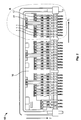
- Fig. 2 shows a rear view of an electrical connector 15 comprising a plurality of press-fit pins 1 according to the present invention.
- the pins 1 are similar to the press-fit pins 1 described above.
- the electrical connector 15 has a housing 16 which is provided with a plurality of cavities 17 in the form of sockets for accommodating a press-fit pin 1 each.
- Fig. 3 is an enlarged view of the detail A of the electrical connector 15 shown in Fig. 2 .
- the press-fit pins 1 are bent in the area of their bending zones 10 with a square angle. In an end position of the pins 1 shown in Fig. 3 an upper portion of the pins 1 reaching from their upper tip 13 to their retaining element 12 is fully inserted into a respective cavity 17.
- a lower portion of the pin from the bending zone 10 down to the press-in zone 4 has an insertion direction I and runs parallel to an insertion direction I' of the connector 15.
- the connector 15 is provided with retaining taps 18.
- the retaining taps 18 and the press-in zones 4 of the pins 1 are protruding from the connector 15 in the insertion directions I, I'.
- the connector 15 together with the pins 1 may be pressed into a PCB having respective cavities or press-in sockets for example, by carrying out a single press-in operation.
- a first spacing direction S 1 centers of the cavities 17 are spaced with a distance s.
- the distance s may be regarded as a common pitch of the cavities 17 and therefore also of pins 1 within the electrical connector 16.
- the sides 6a, 6b of adjacent, i.e. neighboring pins 1 facing each other have a maximal distance s' being the distance s less the width w of the pins 1.
- a minimal distance s" between opposing surfaces of the sides 6a, 6b and 8a, 8b of two adjacent or neighboring pins 1 is the distance s' between their respective sides 6a, 6b less the height h of the protrusions 5a, 5b protruding from the respective opposing sides 6a, 6b belonging to adjacent pins.
- the minimal distance s" between the sides 6a, 6b of adjacent pins 1 is always kept.
- the asymmetrical arrangement of the protrusions 5a, 5b help to interleave the protrusions 5a, 5b on opposing sides 6a, 6b of neighboring pins 1 such that the outer contours of the pins are matched in order to keep a certain distance, i.e. the minimal distance s".
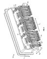
- Fig. 4 shows a perspective view of the connector 15 shown in Fig. 2 .
- press-fit pins 1 are not only aligned in a row in the first spacing direction S 1 but also in another row in a second spacing direction S 2 .
- the protrusions 5a, 5b protrude from the press-fit pins 1 in parallel to the first spacing direction S 1 .
- Any protrusions protruding from the pins 1 in the second spacing direction S 2 could also be displaced along the height direction L of the pins such that a minimal distance s" between the pins 1 is always kept.
- Fig. 5 shows a plurality of press-fit pins 21 according to the prior art.
- the pins 21 have a body portion 22.
- Protrusions 25a, 25b are protruding from opposite sides 26a, 26b of the body portion 22.
- the protrusions 25a, 25b also have a height h in a direction perpendicular to a longitudinal axis I of the pins 21 and adding to their width w.
- the height h of the protrusions 25a, 25b of the pins 21 according to the prior art is similar to the height h of the protrusions 5a, 5b of the pins 1 according to the present invention.
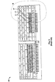
- Fig. 6 shows a rear view of an electrical connector 35 according to the prior art comprising a plurality of press-fit pins 21 according to the prior art.
- the pins 21 are similar to the press-fit pins 21 described above in relation to Fig. 5 .
- the electrical connector 35 has a housing 36 which is provided with a plurality of cavities 37 for accommodating the pins 21. In an end position of the pins 21 shown in Fig. 6 , an upper portion of the pins 21 is fully inserted into a respective cavity 37.
- Fig. 7 is an enlarged detail B of the connector 35 according to the prior art illustrated in Fig. 6 .
- the protrusions 25a, 25b protruding from opposing sides 26a, 26b of neighboring pins 21 according to the prior art are not offset, i.e. distanced along the height direction L of the pins 21, the protrusions 25a, 25b are arranged symmetrically in respect to the longitudinal axis I.
- a minimal distance s'" between the protrusions 25a, 25b in the spacing direction S 1 is smaller than the minimal distance s" according to the present invention.
- the distance s'" is the distance s between the centers of the cavities 37 less the width w of the pins and less two times the height h of the protrusions 25a, 25b.
- a minimal achievable distance s' min i.e. a minimal pitch
- asymmetrically arranged protrusions 5a, 5b according to the present invention have a decisive advantage over the symmetrically arranged protrusions 25a, 25b according to the prior art because the invention allows a smaller minimal distance, i.e. pitch, between the cavities 17 of a connector and therefore a larger density of the pins 1 inserted therein. This enables a further miniaturization of electrical components such as connectors.
- the protrusions 5a, 5b could e.g. have a triangular or any other shape. In case it is desired that the protrusions 5a, 5b form shoulder elements having pressing surfaces 7a, 7b in order to be utilized as press-in shoulders, the protrusions 5a, 5b should have an upper surface, edge or corner.
- the protrusions 5a, 5b could also have different shapes and may be used for another functionality, e.g. as stitch-shoulders and other contact-features that are wider than the very functional areas such as mating and PCB-connection areas because the application of the press-fit pins 1 is not limited to electrical connectors.
- the present invention may be used wherever at minimum two first objects or pins 1 are to be inserted parallel to each other and with a relatively narrow distance between each other into a second object which may be an electrical connector 15 as described herein.
- the first objects needing thereby a minimum of support in the insertion direction I and possibly a guiding along the insertion direction I.
- the sides 8a, 8b of the protrusions 5a, 5b do not have to be running parallel to the longitudinal axis I of the pin.
- the sides 8a, 8b may serve as lateral guiding surfaces which may be beveled such that they help to guide and center the pin 1 within a respective hole or cavity.
Landscapes
- Connector Housings Or Holding Contact Members (AREA)
Abstract
Description
- The present invention relates to a press-fit pin for, in particular, electrical plug-in connectors, comprising a plurality of protrusions protruding from the press-fit pin in a direction essentially perpendicular to a height direction of the press-fit pin, whereby the protrusions that are closest to each other are arranged on opposing sides of the press-fit pin.
- Further, the present invention relates to an electrical connector comprising a plurality of press-fit pins, the plurality of press-fit pins comprising at least one pair of press-fit pins mounted adjacent to and at a predetermined distance from each other, each of the press-fit pins of said pair comprising at least two protrusions sticking out from different sides of the respective press-fit pin.
- Press-fit pins are known and are pressed into printed circuit boards (PCB) for being used as a part of a plug-in connector for example. For pressing the press-fit pins into dies or sockets of the respective elements, a tool must exert high press-in forces on the pin. Therefore, the tools are often supported at so called press-in shoulders which protrude symmetrically from opposing sides of the press-fit pin. The press-in shoulders constitute pressing planes facing in the height direction of the pin for supporting the tool.
- A press-fit pin according to the prior art is described in US-patent application
US 200710010139 A1 - In an electrical connector, the distance, i.e. pitch, between the press-fit pins being used as plug contacts arranged in a row is usually 2.5 to 2.54 mm. This very small distance is reduced even further in areas where protrusions symmetrically sticking out from the sides of adjacent different pins are opposing each other. A further miniaturization of electrical elements such as the electrical connectors mentioned above is impossible because this would mean to reduce the distance between the pins and their protrusions which would then have too close geometries. These may lead to short circuits especially in cases of a presence of metallic particles. Moreover, due to the too close geometries of the pins it is difficult to reliably handle them with the press-in tools and design both the pins and the tools in a way that they will be stable enough and capable for industrial application.
- In view of the disadvantages of the prior art mentioned above, an object underlying the invention is to provide a press-fit pin which enables a further miniaturization of electrical elements, such as connectors, while at least maintaining the stability and capabilities in comparison with the prior art.
- This object is achieved according to the invention for the press-fit pin mentioned in the beinning of the introduction in that the protrusions that are closest to each other are distanced from each other in the height direction.
- For an electrical contact mentioned in the beginning of the description, the object is achieved according to the invention in that at the most one protrusion is arranged between the press-fit pins of said pair at any given height of the press-fit pins.
- These simple solutions provide that the protrusions are unsymmetrical and do not overlap with another protrusion in a direction perpendicular to the height direction of the pin. Regarding a connector, the protrusions next to each other protruding from opposing sides of adjacent press-fit pins are spaced from each other in the height direction. In this way, the distance between the geometries or contours of adjacent pins with smaller distances has nearly the same proportion as between symmetrical contacts with bigger distances, i.e. pitches. In other words, according to the invention, while keeping the narrowest required distance between the pin-geometries, the overall pitch may be reduced. Hence, an advantage of the invention over the prior art is that any components and units comprising press-fit pins according to the invention may have smaller sizes and consequently help saving material and installation place. Above that, the present invention helps to lower the risk of short circuits between adjacent pins and thereby has lower requirements to cleanliness in view of (metallic) particles, compared to the prior art. Further advantages arising therefrom are a realisability of a compliant-contact-technology (press-fit-technology) for narrow pitches with at most the same requirements to tooling and processing as in the prior art. Tools for production and subsequent processing may be designed as same solid as for the existing processes.
- The solution according to the invention can be combined as desired and further improved by the following, further embodiments that are advantageous on their own in each case.
- According to a first possible further embodiment of the invention, at least one of the plurality of protrusions may comprise a pressing plane or surface of which the normal runs essentially parallel to a longitudinal direction of the press-fit pin or the height direction. A tool for exerting a press-in force to the pin may easily be supported at the pressing surface or the pressing surface may be used as a stop when inserting the pin into a socket.
- According to another further possible configuration, at least one of the protrusions sticks out from a side of the press-fit pin. This enables to provide stable press-in-shoulders for example, of which the left and the right halves are placed in different heights on the respective sides of the pin and upon which the press-in force may be applied. The opposite sides of the shoulders may be designed in a similar way, with a distance to the shoulder on the other side of the contact and accordingly the shoulder of an adjacent contact.
- According to another possible further embodiment the handling of a press-fit pin according to the invention is facilitated when the pressing surface is substantially rectangular. Thereby, the area of the pressing surface may be maximized while minimizing the height of the protrusion with which it sticks out from the side of the pin. The outer edge of the substantially rectangular pressing surface sharply delimits the contour of the press-fit pin and facilitates to arrange a plurality of press-fit pins such that their contours interleave while keeping a desired minimal distance between adjacent pins in any height along their height direction.
- According to another possible embodiment of the invention it is possible that a cross-sectional area of the press-fit pin at least in a region comprising one of the protrusions is of substantially rectangular shape. The cross-sectional area lies in a plane having a right angle to the longitudinal axis of the pin. It is also advantageous, when the cross-sectional area in a direction perpendicular to the height direction of the press-fit pin in the region of the protrusions is larger than the cross-sectional area in a region where no protrusion protrudes from one of the sides of the press-fit pin. Thereby, the stability of the press-fit pin in the region of the protrusion is increased in relation to other regions or portions of the pin which have a smaller cross-sectional area. When the protrusions are used as press-in-shoulders for example, it is possible to apply high press-in forces to the pin which has a high stability in the region of the shoulders due to the larger cross-sectional area.
- According to another possible advantageous embodiment, the press-fit pin may be constituted of solid metal material. Thereby, the pin has a high stability and may take up higher forces than a pin having a hollow profile for example.
- A press-fit pin according to the invention may be easily produced if the press-fit pin is stamped from plate material. However, the pin may also be produced from wire for example.
- The invention will be described in more detail by way of example hereinafter using advantageous embodiments and with reference to the drawings. The described embodiments are only possible configurations in which the individual features may however, as described above, be implemented independently of each other or be omitted. Equal elements illustrated in the drawings are provided with equal reference signs. Redundant descriptions of equal elements within different drawings are left out.
-
- Fig. 1
- is a front view of a plurality of press-fit pins designed according to the invention which are arranged as a stamped strip of contacts,
- Fig. 2
- is a rear view of an electrical connector according to the invention comprising a plurality of press-fit pins according to the invention,
- Fig. 3
- is an enlarged view of detail A of the connector shown in
Fig. 2 ; - Fig. 4
- is a perspective view of the electrical connector shown in
Fig. 2 , - Fig. 5
- is a front view of a plurality of press-fit pins according to the prior art,
- Fig. 6
- is a rear view of an electrical connector comprising a plurality of press-fit pins according to the prior art.
- Fig. 7
- is an enlarged view of detail B of the connector shown in
Fig. 6 - The construction of a press-fit pin configured according to the invention will firstly be described in the following with reference to
Fig. 1 which shows a front view of a plurality of press-fit pins 1. The press-fit pins 1 have alongitudinal body portion 2 running in a longitudinal direction or height direction L and having a longitudinal axis I as well as a width w. In the region of alower tip 3 eachpin 1 is provided with a press-inzone 4 constituting a press-in head to be inserted into openings in a counterpart e.g. press-in sockets or press-in holes for contacts on PCBs or the like. The press-inzone 4 is structured such that it provides a good hold of thepin 1 when thepin 1 is inserted into a respective socket, cavity, hole, opening or die. - For exerting a press-in force on the
pins 1 or for other operations or functions, eachpin 1 is provided with a pair ofprotrusions protrusions respective side pin 1. As thesides pins 1, theprotrusions respective sides sides protrusions surface fit pin 1. Thepressing planes pins 1. Hence, thepressing surfaces protrusions pins 1 with the help of a press-in tool (not shown). - In the embodiment of the
pins 1 shown inFig. 1 , theprotrusions Sides respective protrusions pins 1 like thesides body portion 2 of eachpin 1. As theprotrusions sides protrusions pressing surface protrusions pressing surfaces - In the present invention it is an essential feature that the
protrusions protrusions sides protrusions protrusions fit pins 1 in a connector in such a way that theprotrusions different pins 1 do not oppose each other in a direction perpendicular to the height direction L. Theprotrusions sides pressing planes Fig.1 . - Further, according to the embodiment of the
pins 1 shown inFig. 1 , thebody portion 2 of thepins 1 may be provided with one ormore bending zones 10. In the area of the bendingzone 10, thepins 1 may be bent such that they have a 90° kink for example. Thepins 1 are provided with a punched outcontact strip 11 as in the present embodiment, thepins 1 are stamped contacts made from strip or plate material. Thecontact strip 11 may advantageously be used as a carrier strip or holding member for feeding a plurality of press-fit pins 1 into a processing machine. Thecontact strip 11 can be removed before, during or after processing the press-fit pins 1. Alternatively, the pins may also be formed from wire material for example. Theprotrusions pins 1 or may be formed as several bends or by compressing the pins in the height direction L. - Above the
contact strip 11, thepins 1 are provided with a retainingelement 12. The retainingelement 12 helps to securely fix thepins 1 to a connector, a housing, or similar elements or may be used as another press-in shoulder for example. The retainingelement 12 is constituted by lance like edges symmetrically protruding from thesides pins 1 and is much smaller than theprotrusions element 12 is not of particular interest. Between the retainingelement 12 and a sharpenedupper tip 13, thepins 1 are provided with acontact zone 14. Thecontact zone 14 and theupper tip 13 constitute a pin contact when the press-fit pin 1 is inserted into an electrical connector. -
Fig. 2 shows a rear view of anelectrical connector 15 comprising a plurality of press-fit pins 1 according to the present invention. Thepins 1 are similar to the press-fit pins 1 described above. Theelectrical connector 15 has ahousing 16 which is provided with a plurality ofcavities 17 in the form of sockets for accommodating a press-fit pin 1 each. -
Fig. 3 is an enlarged view of the detail A of theelectrical connector 15 shown inFig. 2 . The press-fit pins 1 are bent in the area of theirbending zones 10 with a square angle. In an end position of thepins 1 shown inFig. 3 an upper portion of thepins 1 reaching from theirupper tip 13 to their retainingelement 12 is fully inserted into arespective cavity 17. A lower portion of the pin from the bendingzone 10 down to the press-inzone 4 has an insertion direction I and runs parallel to an insertion direction I' of theconnector 15. - The
connector 15 is provided with retaining taps 18. The retaining taps 18 and the press-inzones 4 of thepins 1 are protruding from theconnector 15 in the insertion directions I, I'. - Hence, the
connector 15 together with thepins 1 may be pressed into a PCB having respective cavities or press-in sockets for example, by carrying out a single press-in operation. - In a first spacing direction S1. centers of the
cavities 17 are spaced with a distance s. Commonly, there is an equal spacing, i.e. distance s, between the centers of thecavities 17. In case of an equal spacing, the distance s may be regarded as a common pitch of thecavities 17 and therefore also ofpins 1 within theelectrical connector 16. Thesides pins 1 facing each other have a maximal distance s' being the distance s less the width w of thepins 1. A minimal distance s" between opposing surfaces of thesides pins 1 is the distance s' between theirrespective sides protrusions sides - As the
protrusions pin 1 are spaced with the distance d in a direction parallel to the longitudinal axis I of the pins, the minimal distance s" between thesides adjacent pins 1 is always kept. In other words, the asymmetrical arrangement of theprotrusions protrusions sides pins 1 such that the outer contours of the pins are matched in order to keep a certain distance, i.e. the minimal distance s".Sides protrusions sides body portions 2 of the pin are always kept at the minimal distance s", while the distance between opposingprotrusions lower shoulder elements protrusions -
Fig. 4 shows a perspective view of theconnector 15 shown inFig. 2 . InFig. 3 it becomes obvious that press-fit pins 1 are not only aligned in a row in the first spacing direction S1 but also in another row in a second spacing direction S2. Theprotrusions fit pins 1 in parallel to the first spacing direction S1. Any protrusions protruding from thepins 1 in the second spacing direction S2 could also be displaced along the height direction L of the pins such that a minimal distance s" between thepins 1 is always kept. -
Fig. 5 shows a plurality of press-fit pins 21 according to the prior art. Thepins 21 have abody portion 22.Protrusions opposite sides body portion 22. Theprotrusions pins 21 and adding to their width w. The height h of theprotrusions pins 21 according to the prior art is similar to the height h of theprotrusions pins 1 according to the present invention. -
Fig. 6 shows a rear view of anelectrical connector 35 according to the prior art comprising a plurality of press-fit pins 21 according to the prior art. Thepins 21 are similar to the press-fit pins 21 described above in relation toFig. 5 . Theelectrical connector 35 has a housing 36 which is provided with a plurality ofcavities 37 for accommodating thepins 21. In an end position of thepins 21 shown inFig. 6 , an upper portion of thepins 21 is fully inserted into arespective cavity 37. -
Fig. 7 is an enlarged detail B of theconnector 35 according to the prior art illustrated inFig. 6 . As theprotrusions sides pins 21 according to the prior art are not offset, i.e. distanced along the height direction L of thepins 21, theprotrusions pins 21 according to the prior art shown inFig. 7 , a minimal distance s'" between theprotrusions cavities 37 less the width w of the pins and less two times the height h of theprotrusions sockets 37 is larger than the minimal achievable distance smin according to the present invention. Consequently, asymmetrically arrangedprotrusions protrusions cavities 17 of a connector and therefore a larger density of thepins 1 inserted therein. This enables a further miniaturization of electrical components such as connectors. - Deviations from the above-described embodiments are possible within the inventive idea. The
protrusions protrusions pressing surfaces protrusions protrusions fit pins 1 is not limited to electrical connectors. The present invention may be used wherever at minimum two first objects orpins 1 are to be inserted parallel to each other and with a relatively narrow distance between each other into a second object which may be anelectrical connector 15 as described herein. - The first objects needing thereby a minimum of support in the insertion direction I and possibly a guiding along the insertion direction I. Hence, the
sides protrusions sides pin 1 within a respective hole or cavity.
Claims (9)
- Press-fit pin (1) for, in particular, electrical plug-in connectors (15), comprising a plurality of protrusions (5a, 5b) protruding from the press-fit pin (1) in a direction essentially perpendicular to a height direction (L) of the press-fit pin, whereby the two protrusions (5a, 5b) that are located closest to each other are arranged on opposing sides (6a, 6b) of the press-fit pin characterized in that the protrusions (5a, 5b) that are closest to each other are distanced from each other in the height direction (L).
- Press-fit pin (1) according to claim 1, characterized in that at least one of the plurality of protrusions (5a, 5b) comprises a pressing surface (7a, 7b, 9a, 9b) of which the normal runs essentially parallel to the height direction (L).
- Press-fit pin (1) according to any one of claims 1 or 2, characterized in that at least one of the protrusions (5a, 5b) sticks out from the side (6a, 6b) of the press-fit pin (1).
- Press-fit pin (1) according to claims 2 or 3, characterized in that the pressing surface (7a, 7b, 9a, 9b) is substantially rectangular.
- Press-fit pin according to any one of claims 1 to 3, characterized in that a cross-sectional area of the press-fit pin (1) at least in a region comprising one of the protrusions (5a, 5b) is of substantially rectangular shape.
- Press-fit pin (1) according to any one of claims 1 to 5, characterized in that a cross-sectional area of the press-fit pin (1) In a region of the protrusions (5a, 5b) is larger than the cross-sectional area In a region where no protrusion (5a, 5b) protrudes from one of the sides (6a, 6b) of the press-fit pin (1).
- Press-fit pin (1) according to any one of claims 1 to 6, characterized in that the press-fit pin (1) is constituted of solid metal material.
- Press-fit pin (1) according to any one of claims 1 to 7, characterized in that the press-fit pin (1) is stamped from plate material.
- Electrical connector (15) comprising a plurality of press-fit pins (1), the plurality of press-fit pins (1) comprising at least one pair of press-fit pins (1) mounted adjacent to and at a predetermined distance (s) from each other, each of the press-fit pins (1) of said pair comprising at least two protrusions (5a, 5b) sticking out from different sides (6a, 6b) of the respective press-fit pin (1), characterized in that at the most one protrusion (5a, 5b) is arranged between the press-fit pins (1) of said pair at any given height of the press-fit pins (1).
Priority Applications (1)
| Application Number | Priority Date | Filing Date | Title |
|---|---|---|---|
| EP08018735A EP2180552A1 (en) | 2008-10-27 | 2008-10-27 | Press-fit pin with unsymmetrical protrusions |
Applications Claiming Priority (1)
| Application Number | Priority Date | Filing Date | Title |
|---|---|---|---|
| EP08018735A EP2180552A1 (en) | 2008-10-27 | 2008-10-27 | Press-fit pin with unsymmetrical protrusions |
Publications (1)
| Publication Number | Publication Date |
|---|---|
| EP2180552A1 true EP2180552A1 (en) | 2010-04-28 |
Family
ID=40467373
Family Applications (1)
| Application Number | Title | Priority Date | Filing Date |
|---|---|---|---|
| EP08018735A Withdrawn EP2180552A1 (en) | 2008-10-27 | 2008-10-27 | Press-fit pin with unsymmetrical protrusions |
Country Status (1)
| Country | Link |
|---|---|
| EP (1) | EP2180552A1 (en) |
Citations (2)
| Publication number | Priority date | Publication date | Assignee | Title |
|---|---|---|---|---|
| EP0271357A2 (en) * | 1986-12-12 | 1988-06-15 | Nec Corporation | Press-fit connector |
| US20070010139A1 (en) | 2005-07-08 | 2007-01-11 | J.S.T. Corporation | Press-fit pin |
-
2008
- 2008-10-27 EP EP08018735A patent/EP2180552A1/en not_active Withdrawn
Patent Citations (2)
| Publication number | Priority date | Publication date | Assignee | Title |
|---|---|---|---|---|
| EP0271357A2 (en) * | 1986-12-12 | 1988-06-15 | Nec Corporation | Press-fit connector |
| US20070010139A1 (en) | 2005-07-08 | 2007-01-11 | J.S.T. Corporation | Press-fit pin |
Similar Documents
| Publication | Publication Date | Title |
|---|---|---|
| JP2803574B2 (en) | Press-in terminal of connector and method of manufacturing the same | |
| US5584709A (en) | Printed circuit board mounted electrical connector | |
| US6814590B2 (en) | Electrical power connector | |
| CN101171724B (en) | Two-piece surface mount head assembly with planar alignment surface | |
| CN100438217C (en) | Electrical connector for memory modules | |
| US6592382B2 (en) | Simplified board connector | |
| US5897401A (en) | Serrated starred pin | |
| CN105870690B (en) | terminal group and connector | |
| CN101128960A (en) | Surface Mount Receptacle Assembly with Planar Alignment Surface | |
| CN1139154C (en) | Testable electric connector for inserter grid mesh array component | |
| JPH10507303A (en) | Electrical connector having integral support structure | |
| US6634899B2 (en) | Card edge connector | |
| US9595782B2 (en) | Pin with angled retention member | |
| JPH04342970A (en) | Spear-shaped holder | |
| EP0546673A2 (en) | Connector with retention feature | |
| KR100515993B1 (en) | Contact for electrical connector and electrical connector comprising the same | |
| KR101029668B1 (en) | Surface Mount Header Assemblies | |
| EP2180552A1 (en) | Press-fit pin with unsymmetrical protrusions | |
| US8007304B2 (en) | Contact strip having pre-break recess with gradient width and deep | |
| KR101032933B1 (en) | Force fit contact and force fit connector using the same | |
| KR102767736B1 (en) | Rectangular wire terminal, connector, method for manufacturing rectangular wire, and method for manufacturing connector | |
| EP2169784A2 (en) | Connector terminal structure, connector and method of assembling connector | |
| EP0139786B1 (en) | Press fit connector insulator and contact | |
| JP7191380B2 (en) | connector | |
| CN106654664A (en) | Connector |
Legal Events
| Date | Code | Title | Description |
|---|---|---|---|
| PUAI | Public reference made under article 153(3) epc to a published international application that has entered the european phase |
Free format text: ORIGINAL CODE: 0009012 |
|
| AK | Designated contracting states |
Kind code of ref document: A1 Designated state(s): AT BE BG CH CY CZ DE DK EE ES FI FR GB GR HR HU IE IS IT LI LT LU LV MC MT NL NO PL PT RO SE SI SK TR |
|
| AX | Request for extension of the european patent |
Extension state: AL BA MK RS |
|
| AKY | No designation fees paid | ||
| STAA | Information on the status of an ep patent application or granted ep patent |
Free format text: STATUS: THE APPLICATION IS DEEMED TO BE WITHDRAWN |
|
| 18D | Application deemed to be withdrawn |
Effective date: 20101029 |
|
| REG | Reference to a national code |
Ref country code: DE Ref legal event code: R108 Effective date: 20110329 Ref country code: DE Ref legal event code: 8566 |