EP2180402A1 - Integrated development framework for composite applications - Google Patents
Integrated development framework for composite applications Download PDFInfo
- Publication number
- EP2180402A1 EP2180402A1 EP09012414A EP09012414A EP2180402A1 EP 2180402 A1 EP2180402 A1 EP 2180402A1 EP 09012414 A EP09012414 A EP 09012414A EP 09012414 A EP09012414 A EP 09012414A EP 2180402 A1 EP2180402 A1 EP 2180402A1
- Authority
- EP
- European Patent Office
- Prior art keywords
- objects
- development
- native
- framework
- integrated
- Prior art date
- Legal status (The legal status is an assumption and is not a legal conclusion. Google has not performed a legal analysis and makes no representation as to the accuracy of the status listed.)
- Ceased
Links
Images







Classifications
-
- G—PHYSICS
- G06—COMPUTING OR CALCULATING; COUNTING
- G06F—ELECTRIC DIGITAL DATA PROCESSING
- G06F8/00—Arrangements for software engineering
- G06F8/20—Software design
-
- G—PHYSICS
- G06—COMPUTING OR CALCULATING; COUNTING
- G06Q—INFORMATION AND COMMUNICATION TECHNOLOGY [ICT] SPECIALLY ADAPTED FOR ADMINISTRATIVE, COMMERCIAL, FINANCIAL, MANAGERIAL OR SUPERVISORY PURPOSES; SYSTEMS OR METHODS SPECIALLY ADAPTED FOR ADMINISTRATIVE, COMMERCIAL, FINANCIAL, MANAGERIAL OR SUPERVISORY PURPOSES, NOT OTHERWISE PROVIDED FOR
- G06Q10/00—Administration; Management
- G06Q10/10—Office automation; Time management
Definitions
- the invention relates generally to software development tools and more particularly to systems, methods, and articles of manufacture for development of composite applications.
- composite application generally refers to an application built by combining multiple existing functions into a new application.
- Composite applications may leverage enterprise and enterprise-ready sources, for example existing modules or even enterprise web services of information.
- Composite applications can be built using any technology or architecture.
- a composite application consists of functionality drawn from several different sources.
- the components may be individual selected functions from within other applications, or entire systems whose outputs have been packaged as business functions, modules, or web services.
- Composite applications often incorporate orchestration of "local" application logic to control how the composed functions interact with each other to produce the new, derived functionality.
- an integrated development environment and related capabilities for developing a composite application there is provided an integrated development environment and related capabilities for developing a composite application.
- Figures 1A , 1B , 1C , 1D , 1E and 1F illustrate various aspects of an integrated development environment, according to various embodiments of the inventive subject matter.
- Figures 2A , 2B , 2C , 2D , 2E , 2F , 2G , 2H , 2I , and 2J illustrate various example embodiments of a user interface for an integrated development environment, according to the inventive subject matter.
- Figure 3 illustrates a flow chart of a method, according to one example embodiment of the inventive subject matter.
- Figure 4 illustrates a computing platform, according to one example embodiment of the inventive subject matter.
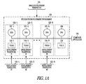
- FIG. 1A there is illustrated an overview of an integrated development environment 100 used to develop a composite application 105.
- Environment 100 is used to integrate the development objects (DOs) 107-1, 107-2 and 107-n and development tools 124-1, 124-2 and 124-n of respective heterogeneous development frameworks 120-1, 120-2 ... 120-n, each having a respective development perspective 123-1, 123-2 and 123-n, into a single development environment providing a single development perspective 101.
- objects 107 are non-native to environment 100.
- Their respective development frameworks 120 may exist outside of environment 100.
- environment 100 further includes additional development objects 108 and development tools 126 that are native to environment 100.
- Non-native objects 107 and tools 124 may be less tightly integrated with environment 100 than object 108 and tools 126.
- the content of tools 124 may be imported into environment 100, but with read-only support (e.g., creation of development objects 107 is not supported).
- environment 100 is a software development framework and includes support programs, code libraries, a scripting language, and other software to help develop and connect together the different components of a software project.
- environment 100 includes a graphical user interface 112, a plurality of development tools 114, a meta-model repository 115, an application programming interface (API) 116, and error checking functions 117 and application runtime functions 113 necessary to run a composite application 105.
- API application programming interface
- composite application 105 includes functionality drawn from several different sources.
- the components of composite application 105 may be individual selected functions from within other applications, or entire systems whose outputs have been packaged as business functions, modules, or web services.
- composite application 105 in one example embodiment, may include one or more of the heterogeneous development objects 107-1, 107-2...107-n that are native to the one or more respective heterogeneous development frameworks 120-1, 120-2 ... 120-n, and non-native to environment 100, and one or more development objects 108-1, 108-2 ... 108-n that are native to the integrated development environment 100.
- Objects 107 and/or objects 108 may be collectively referred to herein as objects 109.
- Native development objects 108, and non-native development objects 107 interface with the environment 100 through the application programming interface (API) 116.
- API application programming interface
- one or more objects 107 used in one of the respective frameworks 120 are not capable of use without modification in another one of the respective frameworks 120.
- one or more objects 108 native to environment 100 are not capable of use in native form with one or more of the frameworks 120.
- objects 107 include adaptors 111 enabling the non-native objects 107 to interface with API 116.
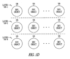
- composite application 105 further includes, in one example embodiment, one or more layers 106-1, 106-2 ... 106-n.
- a layer is a group of classes that have the same set of link-time module dependencies to other modules.
- a layer may be formed of a group of reusable components that are reusable in similar circumstances.
- These layers can include, but are not limited to, a web-program development layer, a service layer, a user interface technologies layer, a process layer, and/or any other layers.
- a composite application 105 may include only one layer 106, such as a process-layer, or many layers. While specific examples of layers are enumerated above, the invention is in no way limited to any particular layers or combination of layers.
- the heterogeneous development frameworks 120-1, 120-2 ... 120-n are each designed for developing programs using corresponding programming models 121-1, 121-2 ... 120-n.
- a programming model is an abstract conceptual view of the structure and operation of a computing system. Such environments and models may be, for example, for development of web portals, guided procedures, visual composition of user interfaces, or web-based applications.
- Development frameworks 120-1, 120-2 ... 120-n each include respective development tool sets 124-1, 124-2 ... 124-n, native to these environments.
- Tool sets 124 each include a plurality of tools 125 that are used to develop programs within these environments, and in particular compose or edit objects 107 used in such programs.
- Tools 125 are, in one example embodiment, programs or applications that software developers use to create, debug, maintain, or otherwise support other programs and applications.
- development tools 114 accessible in environment 100 include one or more of the tool sets 124 native to the developmental frameworks 120, such that a developer may access these tools if composing or editing an object 107 within environment 100.
- the integrated development environment 100 enables a developer to implement a composite application 105 using heterogeneous objects 107 from heterogeneous development frameworks 120 and using heterogeneous tool sets 124, all from a single user interface 112.
- environment 100 subsumes all editors and views that are specific for any of the development frameworks 120, providing at least the basic functionality for editing a composite application 105.
- Development in environment 100 is further supported with model- and code-generation-based methods via tools that store models 121 in a meta-model repository 115.
- the integrated development environment 100 provides a user interface 112 that is used to browse, edit, and compose composite applications 105, and in particular development objects 109 and the relationships and dependencies between those objects.
- Objects 109 are displayed in a tree view in a composite explorer 210, illustrated in more detail in Figure 2B , in graphical views in the composite designer 212, illustrated in more detail in Figure 2C , and in a detail view window 214.
- An outline view window 216 is used to display an outline view of the composite application 105.
- a palette 218 of development tools, menus, and options to support development are also provided.
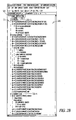
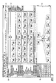
- FIG. 2B illustrates an example view of the composite explorer 210 in more detail.
- composite explorer 210 integrates all relevant content provided from the different frameworks 120 into one view 211.
- "Product" or "software component” entities may be used as a root entity 213 in the tree.
- the objects 109 contained in the given product or software component are structured in five layers, a portal layer 220-1, a processes layer 220-2, a user-interface (UI) layer 220-3, a business logic layer 220-4, and an infrastructure or external services layer 220-5 (not shown in Figure 2B ).
- Composite explorer 210 makes all the tasks needed for composite application development accessible from one explorer view 211. As such, there is no need to switch the perspective in development environment 100 in order to develop a composite application 105 using objects 109 in different layers or from different programming models or frameworks.
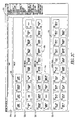
- Figure 2C illustrates the composite designer 212, which shows an overview of all the main (re-usable) development objects 109 of a composite application in a graphical view.
- the development objects 109 are structured in layers 106, for example but not by way of limitation, a portal layer 220-1, a process layer 220-2, UI layer 220-3, a business logic layer 220-4, and an external services layer 220-5.
- the composite designer 212 gives a quick overview of the content of a composite application 105, and may be the entry point for composite application development.
- actions like Show Relations 231, Navigate to Tool Editor 232, Trigger Check Framework 233 and others can be triggered from the overview using pop-up or drop-down navigation menus 230 as for example shown in Figures 2D and 2E .
- Figure 2D is an example interface illustrating menus 230 used to navigate from the composite designer 212 to a tool specific editor to edit a development object 234.
- These editors may be native to the development environment 100, or non-native, for example supported on an external server.
- the first tool editor 232 option 232-1 is to open the editor inside a composite designer perspective.
- the second option 232-2 is to open the editor in a tool specific perspective.
- Figure 2E illustrates an example interface allowing a user to navigate from the composite designer 212 to the composite explorer 210.
- the user may select an element in the composite designer 212 and use the menu option 235 to display the corresponding object 234 in the explorer view 211.
- these views can include, but not by way of limitation, Composite Explorer 236-1, Navigator 236-2, Outline 236-3, Package Explorer 236-4, Project Explorer 236-5, and Component Navigator 236-6.
- Figure 2F illustrates an example view 240, selected from the menu options, that displays relations 242 between the main development objects 109 of different toolsets 124 of a composite application 105.
- the relations 242 can be shown in a separate view, referred to as a "relations view,” or in the composite designer 212 for example as activated by a menu button.
- the relations view supports graphical and textual, for example form-based, visualization of the relations, for example a relation from a first web-based component 245 to various objects 247 of the integrated development environment 100.
- two modes of relationship exposure are possible: a basic mode that shows only relations between main objects 109 with no details of internal structure shown and an extended mode that shows detailed relations including internal structure between development objects 109.
- Figure 2G illustrates an example interface 250 to check consistency between different toolsets.
- the consistency check is done on the operational level between the different toolsets, for example for the web component 245 that is consuming an application service operation.
- the consistency check notifies a developer at design time in case of incompatible changes of an operation. Mapping of Input/Output parameters from usage (e.g. a web model class) to used object (e.g., an application service operation) are shown in a check result dialog 252.
- Figure 2H illustrates an example check result dialog 252. It shows parameter/attribute mappings between a source 254 and a target 256 operation.
- an operation has an input/output structure.
- the dialog 252 may show the inconsistencies 258 between the structures of the source 254 and target 256 operations.
- Figure 2I illustrates an example interface allowing a user to create new development objects 109 in the graphical overview using palette 218, with no need to switch perspective. This can provide one common UI behavior to create new entities across all frameworks 120 and associated toolsets 124.
- Figure 2J illustrates an example interface to create relations on-the-fly between developments objects 109 of different toolsets 124 via the Connection Palette Tool 260 in the graphical overview.
- the tool 260 can create a relation from the web component 245 to the application service 246.
- this improves developer productivity by automatically setting all preconditions, for example object 109 dependency, access permissions, and others so that relation creation is possible.
- manual steps in creating relations are no longer necessary.
- environment 100 allows non-native objects 107 from a plurality of different development frameworks to be edited from the same user interface 112.
- the tools 300 include a plurality of tool sets 124 that are native to respective development frameworks 120.
- Each development framework 120 may also include a context menu entry to navigate to objects 109 of other programming models.
- FIG. 3 there is shown a flow diagram 300 illustrating one example embodiment of one example mode of use of the development environment 100. While a specific order of operations is given, it shall be understood that the order of operations may be varied or used in any combination.
- a composite application 105 is selected and loaded 305 into the environment 100.
- Objects of the composite application 105 are displayed 310 together in a tree view and/or in a graphical view showing the layer to which each object belongs. Relationships between the objects shown in the graphical view are graphically indicated 315, for example across all objects or for a selected object.
- a user can select an object in any layer and navigate 320 to a target object in the same or different layer.
- the target object's function may be edited 325, for example by editing the code of the object, by altering the object's relationships, or by other means. Or, a new object may be created.
- the user may navigate back to the source object.
- the user may check 330 the composite application 105 and any errors in the composite application are displayed 335 to the developer at design time. The developer may then debug 340 any problems with the composite application 105 prior to run time.
- environment 100 may use breadcrumbs wherein every object of a programming model that was a navigation target is also one node in the breadcrumb so that by clicking on a node a backward navigation is possible.
- a view provided by environment 100 may contain the breadcrumb with a collection and history of all objects 109 and the development framework 120 of the programming model to handle the objects.
- each framework/tool provides a context menu entry to navigate to entities of other programming models. Accordingly, for example, a developer can start from an entity in a process and navigate to a user interface. Next, in the perspective of the user interface programming model the developers can navigate to a used service. Then, within the implementation of the service the developer can change the coding. Finally, after the change in the code a developer navigates back to the user interface or the process and is able to test the change.
- the integrated development environment 100 may integrate non-native development frameworks 120 either directly or indirectly.
- some of the tool sets 124 may be built into environment 100, and others may be downloaded from an external source, such as a server holding server-based tools 124.
- a composition application 105 matches to a software component, and the content of the different frameworks 120 in a composite application 105 are stored in specific development objects 109.
- Platform 400 may host the development environment 100.
- development environment 100 may be stored on one or more machine readable media 420 on platform 400, such as a hard drive or memory circuits, and execute on one or more processors 410.
- Platform 400 may take the form of one or more servers or other computing systems, such as workstations, personal computers, or mainframes.
- an article of manufacture such as a computer, a memory system, a magnetic or optical disk, some other storage device, and/or any type of electronic device or system may include one or more processors coupled to a machine-readable medium such as a memory (e.g., removable storage media, as well as any memory including an electrical, optical, or electromagnetic conductor) having instructions stored thereon (e.g., computer program instructions), which when executed by the one or more processors result in performing any of the actions described with respect to the methods above.
- a machine-readable medium such as a memory (e.g., removable storage media, as well as any memory including an electrical, optical, or electromagnetic conductor) having instructions stored thereon (e.g., computer program instructions), which when executed by the one or more processors result in performing any of the actions described with respect to the methods above.
- the machine may take the form of a computer system having a processor coupled to a number of components directly, and/or using a bus.
- Such components may include main memory, static or non-volatile memory, and mass storage.
- Other components coupled to the processor may include an output device, such as a video display, an input device, such as a keyboard, a cursor control device, such as a mouse, and a signal generation device, such as a speaker.
- a network interface device to couple the processor and other components to a network may also be coupled to the bus.
- the instructions may further be transmitted or received over the network via the network interface device utilizing any one of a number of well-known transfer protocols (e.g., HTTP). Any of these elements coupled to the bus may be absent, present singly, or present in plural numbers, depending on the specific example to be realized.
- the processor, the memories and the mass storage device may each include instructions which, when executed, cause the machine to perform any one or more of the methods described herein.
- the machine operates as a standalone device or may be connected (e.g., networked) to other machines.
- the machine may operate in the capacity of a server or a client machine in server-client network environment, or as a peer machine in a peer-to-peer (or distributed) network environment.
- the machine may be a personal computer (PC), a tablet PC, a set-top box (STB), a Personal Digital Assistant (PDA), a cellular telephone, a web appliance, a network router, switch or bridge, or any machine capable of executing a set of instructions (sequential or otherwise) that specify actions to be taken by that machine.
- PC personal computer
- PDA Personal Digital Assistant
- STB set-top box
- WPA Personal Digital Assistant
- a cellular telephone a web appliance
- network router switch or bridge
- machine shall also be taken to include any collection of machines that individually or jointly execute a set (or multiple sets) of instructions to perform any one or more of the methodologies discussed herein.
- machine-readable medium should be taken to include a single medium or multiple media (e.g., a centralized or distributed database, and/or associated caches and servers, and or a variety of storage media, such as the processor, registers, memories, and the mass storage device) that store the one or more sets of instructions.
- the term “machine-readable medium” shall also be taken to include any medium that is capable of storing, encoding or carrying a set of instructions for execution by the machine and that cause the machine to perform any one or more of the methodologies of the present invention, or that is capable of storing, encoding or carrying data structures utilized by or associated with such a set of instructions.
- the term “machine-readable medium” shall accordingly be taken to include tangible media, such as solid-state memories and optical and magnetic media.
- an integrated development environment 100 that provides, among other things, for development of composite applications from a single perspective.
- the environment 100 provides for display, editing, and creation of objects in different layers of the application and from different heterogeneous development environments using heterogeneous development tools.
- Environment 100 enables a developer to view relationships between objects in different layers, and to navigate from an object in one layer to an object in another layer, and to check any edits to the application in design time. Environment 100 therefore allows a developer to more readily develop or debug composite applications.
Landscapes
- Engineering & Computer Science (AREA)
- Theoretical Computer Science (AREA)
- Business, Economics & Management (AREA)
- Physics & Mathematics (AREA)
- General Engineering & Computer Science (AREA)
- Entrepreneurship & Innovation (AREA)
- Human Resources & Organizations (AREA)
- Strategic Management (AREA)
- Software Systems (AREA)
- General Physics & Mathematics (AREA)
- Operations Research (AREA)
- Tourism & Hospitality (AREA)
- General Business, Economics & Management (AREA)
- Quality & Reliability (AREA)
- Marketing (AREA)
- Economics (AREA)
- Data Mining & Analysis (AREA)
- Stored Programmes (AREA)
Abstract
There is disclosed an integrated development environment for development of a composite application, wherein the development environment integrates a plurality of different heterogeneous development frameworks to provide a single user interface and perspective for developing a composite application including components from the different heterogeneous frameworks. In the environment, objects from different frameworks and layers may be viewed simultaneously, navigated between, edited and composed. Error checking functionality allows edits across different layers or objects of different frameworks to be checked at design time.
Description
- The invention relates generally to software development tools and more particularly to systems, methods, and articles of manufacture for development of composite applications.
- In computing, the term "composite application" generally refers to an application built by combining multiple existing functions into a new application. Composite applications may leverage enterprise and enterprise-ready sources, for example existing modules or even enterprise web services of information. Composite applications can be built using any technology or architecture.
- A composite application consists of functionality drawn from several different sources. The components may be individual selected functions from within other applications, or entire systems whose outputs have been packaged as business functions, modules, or web services. Composite applications often incorporate orchestration of "local" application logic to control how the composed functions interact with each other to produce the new, derived functionality.
- According to various example embodiments there is provided an integrated development environment and related capabilities for developing a composite application.
-
Figures 1A ,1B ,1C ,1D ,1E and 1F illustrate various aspects of an integrated development environment, according to various embodiments of the inventive subject matter. -
Figures 2A ,2B ,2C ,2D ,2E ,2F ,2G ,2H ,2I , and2J illustrate various example embodiments of a user interface for an integrated development environment, according to the inventive subject matter. -
Figure 3 illustrates a flow chart of a method, according to one example embodiment of the inventive subject matter. -
Figure 4 illustrates a computing platform, according to one example embodiment of the inventive subject matter. - In the following detailed description of exemplary embodiments of the invention, reference is made to the accompanying drawings which form a part hereof, and in which is shown, by way of illustration, specific exemplary embodiments in which the invention may be practiced. These embodiments are described in sufficient detail to enable those skilled in the art to practice the invention, and it is to be understood that other embodiments may be utilized and that logical, mechanical, electrical, and other changes may be made without departing from the scope of the present invention.
- Referring now to
Figure 1A there is illustrated an overview of an integrateddevelopment environment 100 used to develop acomposite application 105.Environment 100 is used to integrate the development objects (DOs) 107-1, 107-2 and 107-n and development tools 124-1, 124-2 and 124-n of respective heterogeneous development frameworks 120-1, 120-2 ... 120-n, each having a respective development perspective 123-1, 123-2 and 123-n, into a single development environment providing asingle development perspective 101. In an embodiment,objects 107 are non-native toenvironment 100. Theirrespective development frameworks 120 may exist outside ofenvironment 100. According to one example embodiment,environment 100 further includesadditional development objects 108 anddevelopment tools 126 that are native toenvironment 100.Non-native objects 107 andtools 124 may be less tightly integrated withenvironment 100 thanobject 108 andtools 126. In an example embodiment, the content oftools 124 may be imported intoenvironment 100, but with read-only support (e.g., creation ofdevelopment objects 107 is not supported). According to one example embodiment,environment 100 is a software development framework and includes support programs, code libraries, a scripting language, and other software to help develop and connect together the different components of a software project. As illustrated inFigure 1B ,environment 100 includes agraphical user interface 112, a plurality ofdevelopment tools 114, a meta-model repository 115, an application programming interface (API) 116, anderror checking functions 117 andapplication runtime functions 113 necessary to run acomposite application 105. - As described further below,
composite application 105 includes functionality drawn from several different sources. According to one example embodiment, the components ofcomposite application 105 may be individual selected functions from within other applications, or entire systems whose outputs have been packaged as business functions, modules, or web services. As illustrated inFigure 1A and1C ,composite application 105, in one example embodiment, may include one or more of the heterogeneous development objects 107-1, 107-2...107-n that are native to the one or more respective heterogeneous development frameworks 120-1, 120-2 ... 120-n, and non-native toenvironment 100, and one or more development objects 108-1, 108-2 ... 108-n that are native to theintegrated development environment 100.Objects 107 and/orobjects 108 may be collectively referred to herein asobjects 109.Native development objects 108, andnon-native development objects 107, interface with theenvironment 100 through the application programming interface (API) 116. In one embodiment, one ormore objects 107 used in one of therespective frameworks 120 are not capable of use without modification in another one of therespective frameworks 120. Further, one ormore objects 108 native toenvironment 100 are not capable of use in native form with one or more of theframeworks 120. According to one embodiment,objects 107 includeadaptors 111 enabling thenon-native objects 107 to interface withAPI 116. - As illustrated in
Figure 1D ,composite application 105 further includes, in one example embodiment, one or more layers 106-1, 106-2 ... 106-n. In object-oriented design, a layer is a group of classes that have the same set of link-time module dependencies to other modules. In other words, a layer may be formed of a group of reusable components that are reusable in similar circumstances. These layers can include, but are not limited to, a web-program development layer, a service layer, a user interface technologies layer, a process layer, and/or any other layers. Acomposite application 105 may include only onelayer 106, such as a process-layer, or many layers. While specific examples of layers are enumerated above, the invention is in no way limited to any particular layers or combination of layers. - According to one example embodiment illustrated in
Figure 1E , the heterogeneous development frameworks 120-1, 120-2 ... 120-n are each designed for developing programs using corresponding programming models 121-1, 121-2 ... 120-n. According to one embodiment, a programming model is an abstract conceptual view of the structure and operation of a computing system. Such environments and models may be, for example, for development of web portals, guided procedures, visual composition of user interfaces, or web-based applications. Development frameworks 120-1, 120-2 ... 120-n each include respective development tool sets 124-1, 124-2 ... 124-n, native to these environments.Tool sets 124 each include a plurality oftools 125 that are used to develop programs within these environments, and in particular compose or editobjects 107 used in such programs.Tools 125 are, in one example embodiment, programs or applications that software developers use to create, debug, maintain, or otherwise support other programs and applications. - According to one example embodiment illustrated in
Figure 1F ,development tools 114 accessible inenvironment 100 include one or more of thetool sets 124 native to thedevelopmental frameworks 120, such that a developer may access these tools if composing or editing anobject 107 withinenvironment 100. Thus, the integrateddevelopment environment 100 enables a developer to implement acomposite application 105 usingheterogeneous objects 107 fromheterogeneous development frameworks 120 and usingheterogeneous tool sets 124, all from asingle user interface 112. Accordingly,environment 100 subsumes all editors and views that are specific for any of thedevelopment frameworks 120, providing at least the basic functionality for editing acomposite application 105. Development inenvironment 100 is further supported with model- and code-generation-based methods via tools that storemodels 121 in a meta-model repository 115. - Referring now to
Figures 2A through 2I , one example embodiment of auser interface 112 and associated functionality is described. According to oneexample embodiment 200 illustrated inFigures 2A , the integrateddevelopment environment 100 provides auser interface 112 that is used to browse, edit, and composecomposite applications 105, and inparticular development objects 109 and the relationships and dependencies between those objects.Objects 109 are displayed in a tree view in acomposite explorer 210, illustrated in more detail inFigure 2B , in graphical views in thecomposite designer 212, illustrated in more detail inFigure 2C , and in adetail view window 214. Anoutline view window 216 is used to display an outline view of thecomposite application 105. Apalette 218 of development tools, menus, and options to support development are also provided. -
Figure 2B illustrates an example view of thecomposite explorer 210 in more detail. In this example embodiment,composite explorer 210 integrates all relevant content provided from thedifferent frameworks 120 into oneview 211. "Product" or "software component" entities may be used as aroot entity 213 in the tree. In one example embodiment, theobjects 109 contained in the given product or software component are structured in five layers, a portal layer 220-1, a processes layer 220-2, a user-interface (UI) layer 220-3, a business logic layer 220-4, and an infrastructure or external services layer 220-5 (not shown inFigure 2B ).Composite explorer 210 makes all the tasks needed for composite application development accessible from oneexplorer view 211. As such, there is no need to switch the perspective indevelopment environment 100 in order to develop acomposite application 105 usingobjects 109 in different layers or from different programming models or frameworks. -
Figure 2C illustrates thecomposite designer 212, which shows an overview of all the main (re-usable)development objects 109 of a composite application in a graphical view. In one embodiment, thedevelopment objects 109 are structured inlayers 106, for example but not by way of limitation, a portal layer 220-1, a process layer 220-2, UI layer 220-3, a business logic layer 220-4, and an external services layer 220-5. According to one example embodiment, thecomposite designer 212 gives a quick overview of the content of acomposite application 105, and may be the entry point for composite application development. According to one example embodiment, actions likeShow Relations 231, Navigate toTool Editor 232,Trigger Check Framework 233 and others, can be triggered from the overview using pop-up or drop-down navigation menus 230 as for example shown inFigures 2D and2E . -
Figure 2D is an exampleinterface illustrating menus 230 used to navigate from thecomposite designer 212 to a tool specific editor to edit adevelopment object 234. These editors may be native to thedevelopment environment 100, or non-native, for example supported on an external server. In one embodiment there are three navigation/editing options. Thefirst tool editor 232 option 232-1 is to open the editor inside a composite designer perspective. The second option 232-2 is to open the editor in a tool specific perspective. Lastly, there is an option 232-3 to open a tool specific graphical modeler.Figure 2E illustrates an example interface allowing a user to navigate from thecomposite designer 212 to thecomposite explorer 210. For example, the user may select an element in thecomposite designer 212 and use themenu option 235 to display thecorresponding object 234 in theexplorer view 211. In one embodiment these views can include, but not by way of limitation, Composite Explorer 236-1, Navigator 236-2, Outline 236-3, Package Explorer 236-4, Project Explorer 236-5, and Component Navigator 236-6. -
Figure 2F illustrates anexample view 240, selected from the menu options, that displaysrelations 242 between the main development objects 109 ofdifferent toolsets 124 of acomposite application 105. Therelations 242 can be shown in a separate view, referred to as a "relations view," or in thecomposite designer 212 for example as activated by a menu button. In one embodiment, the relations view supports graphical and textual, for example form-based, visualization of the relations, for example a relation from a first web-basedcomponent 245 tovarious objects 247 of the integrateddevelopment environment 100. In one embodiment, two modes of relationship exposure are possible: a basic mode that shows only relations betweenmain objects 109 with no details of internal structure shown and an extended mode that shows detailed relations including internal structure between development objects 109. -
Figure 2G illustrates anexample interface 250 to check consistency between different toolsets. In one embodiment, the consistency check is done on the operational level between the different toolsets, for example for theweb component 245 that is consuming an application service operation. The consistency check notifies a developer at design time in case of incompatible changes of an operation. Mapping of Input/Output parameters from usage (e.g. a web model class) to used object (e.g., an application service operation) are shown in acheck result dialog 252. -
Figure 2H illustrates an examplecheck result dialog 252. It shows parameter/attribute mappings between asource 254 and atarget 256 operation. In an example embodiment, an operation has an input/output structure. Thedialog 252 may show theinconsistencies 258 between the structures of thesource 254 and target 256 operations. -
Figure 2I illustrates an example interface allowing a user to create new development objects 109 in the graphicaloverview using palette 218, with no need to switch perspective. This can provide one common UI behavior to create new entities across allframeworks 120 and associatedtoolsets 124. -
Figure 2J illustrates an example interface to create relations on-the-fly between developments objects 109 ofdifferent toolsets 124 via theConnection Palette Tool 260 in the graphical overview. For example, thetool 260 can create a relation from theweb component 245 to theapplication service 246. In one example embodiment, this improves developer productivity by automatically setting all preconditions, forexample object 109 dependency, access permissions, and others so that relation creation is possible. As such, in this embodiment, manual steps in creating relations are no longer necessary. - Accordingly,
environment 100 allowsnon-native objects 107 from a plurality of different development frameworks to be edited from thesame user interface 112. According to one example embodiment, thetools 300 include a plurality of tool sets 124 that are native torespective development frameworks 120. Eachdevelopment framework 120 may also include a context menu entry to navigate toobjects 109 of other programming models. - Referring now to
Figure 3 , there is shown a flow diagram 300 illustrating one example embodiment of one example mode of use of thedevelopment environment 100. While a specific order of operations is given, it shall be understood that the order of operations may be varied or used in any combination. Acomposite application 105 is selected and loaded 305 into theenvironment 100. Objects of thecomposite application 105, at least two of which are native to respective different development environments, are displayed 310 together in a tree view and/or in a graphical view showing the layer to which each object belongs. Relationships between the objects shown in the graphical view are graphically indicated 315, for example across all objects or for a selected object. A user can select an object in any layer and navigate 320 to a target object in the same or different layer. The target object's function may be edited 325, for example by editing the code of the object, by altering the object's relationships, or by other means. Or, a new object may be created. The user may navigate back to the source object. In addition, the user may check 330 thecomposite application 105 and any errors in the composite application are displayed 335 to the developer at design time. The developer may then debug 340 any problems with thecomposite application 105 prior to run time. - According to one example embodiment,
environment 100 may use breadcrumbs wherein every object of a programming model that was a navigation target is also one node in the breadcrumb so that by clicking on a node a backward navigation is possible. A view provided byenvironment 100 may contain the breadcrumb with a collection and history of allobjects 109 and thedevelopment framework 120 of the programming model to handle the objects. According to one example embodiment, each framework/tool provides a context menu entry to navigate to entities of other programming models. Accordingly, for example, a developer can start from an entity in a process and navigate to a user interface.
Next, in the perspective of the user interface programming model the developers can navigate to a used service. Then, within the implementation of the service the developer can change the coding. Finally, after the change in the code a developer navigates back to the user interface or the process and is able to test the change. - According to another example embodiment, the integrated
development environment 100 may integratenon-native development frameworks 120 either directly or indirectly. For example, some of the tool sets 124 may be built intoenvironment 100, and others may be downloaded from an external source, such as a server holding server-basedtools 124. According to another example embodiment, acomposition application 105 matches to a software component, and the content of thedifferent frameworks 120 in acomposite application 105 are stored in specific development objects 109. - Referring now to
Figure 4 there is illustrated acomputing platform 400 that may host thedevelopment environment 100. According to one example embodiment,development environment 100 may be stored on one or more machinereadable media 420 onplatform 400, such as a hard drive or memory circuits, and execute on one ormore processors 410.Platform 400 may take the form of one or more servers or other computing systems, such as workstations, personal computers, or mainframes. - Thus, other embodiments may be realized. For example, an article of manufacture, such as a computer, a memory system, a magnetic or optical disk, some other storage device, and/or any type of electronic device or system may include one or more processors coupled to a machine-readable medium such as a memory (e.g., removable storage media, as well as any memory including an electrical, optical, or electromagnetic conductor) having instructions stored thereon (e.g., computer program instructions), which when executed by the one or more processors result in performing any of the actions described with respect to the methods above.
- The machine may take the form of a computer system having a processor coupled to a number of components directly, and/or using a bus. Such components may include main memory, static or non-volatile memory, and mass storage. Other components coupled to the processor may include an output device, such as a video display, an input device, such as a keyboard, a cursor control device, such as a mouse, and a signal generation device, such as a speaker. A network interface device to couple the processor and other components to a network may also be coupled to the bus. The instructions may further be transmitted or received over the network via the network interface device utilizing any one of a number of well-known transfer protocols (e.g., HTTP). Any of these elements coupled to the bus may be absent, present singly, or present in plural numbers, depending on the specific example to be realized.
- The processor, the memories and the mass storage device may each include instructions which, when executed, cause the machine to perform any one or more of the methods described herein. In some examples, the machine operates as a standalone device or may be connected (e.g., networked) to other machines. In a networked environment, the machine may operate in the capacity of a server or a client machine in server-client network environment, or as a peer machine in a peer-to-peer (or distributed) network environment. The machine may be a personal computer (PC), a tablet PC, a set-top box (STB), a Personal Digital Assistant (PDA), a cellular telephone, a web appliance, a network router, switch or bridge, or any machine capable of executing a set of instructions (sequential or otherwise) that specify actions to be taken by that machine. Further, the term "machine" shall also be taken to include any collection of machines that individually or jointly execute a set (or multiple sets) of instructions to perform any one or more of the methodologies discussed herein.
- The term "machine-readable medium" should be taken to include a single medium or multiple media (e.g., a centralized or distributed database, and/or associated caches and servers, and or a variety of storage media, such as the processor, registers, memories, and the mass storage device) that store the one or more sets of instructions. The term "machine-readable medium" shall also be taken to include any medium that is capable of storing, encoding or carrying a set of instructions for execution by the machine and that cause the machine to perform any one or more of the methodologies of the present invention, or that is capable of storing, encoding or carrying data structures utilized by or associated with such a set of instructions. The term "machine-readable medium" shall accordingly be taken to include tangible media, such as solid-state memories and optical and magnetic media.
- Accordingly, described above is an integrated
development environment 100 that provides, among other things, for development of composite applications from a single perspective. Theenvironment 100 provides for display, editing, and creation of objects in different layers of the application and from different heterogeneous development environments using heterogeneous development tools.Environment 100 enables a developer to view relationships between objects in different layers, and to navigate from an object in one layer to an object in another layer, and to check any edits to the application in design time.Environment 100 therefore allows a developer to more readily develop or debug composite applications.
Claims (15)
- A system comprising:an integrated development framework to develop a composite application using at least a plurality of non-native development objects, wherein the non-native development objects are native to respective programming models using respective non-native development tools, wherein the composite application further includes a plurality of layers and the objects belong to one or more of the layers;the integrated development framework including an application programming interface (API) used by the non-native development objects to communicate with the integrated development framework;the integrated development framework including a graphical user interface providing a visual development framework to:(a) simultaneously display at least two of the non-native development objects from at least two of the different programming models;(b) display an indication of the layers of the composite application and so that the at least two objects are displayed to indicate to which of the layers they belong;(c) display one or more relationships between the displayed development objects;(d) edit one or more of the displayed development objects or a relationship defined between the objects;(e) enable a user to navigate between objects displayed in different layers;(f) enable a user to edit one or more relationships between objects in different layers; andthe integrated development framework further including at least one error-checking function to check edited objects and the edited relationships between the objects and to indicate to a user any errors identified by the check.
- A system according to claim 1 further wherein the integrated development environment includes a development tool function to access and use a non-native development tool to edit a non-native software object inside the visual development framework, and/orfurther wherein the user interface includes at least one navigation function to navigate between the at least two non-native development objects, wherein the navigation includes selecting one of the non-native objects and in response thereto at least identifying to a user at least one other non-native object that is related to the selected non-native object, and/orfurther wherein the error-checking function applies at least one rule to determine if an edit to a programming object or an object relationship results in an execution error at runtime of the composite application, and/orfurther wherein at least one of the non-native development tools includes an adaptor to enable it to communicate with the application programming interface of the integrated development framework, and/orfurther wherein the non-native development objects are displayed so that they are visually associated with a graphical representation of the software layers.
- A system according to any one of the preceding claims further wherein the user interface includes at least one user-selectable relationship display option to cause the system to display the relationships between the at least two non-native development objects, wherein the relationships include dependencies between the at least two non-native development objects.
- A system according to any one of the preceding claims further including one or more functions to allow a user working in the visual development framework to:navigate from a source software object in one of the layers to a target software object in another of the layers;change the coding of the target software object; andfollowing changing the code navigate back to the source software object and test the change using the at least one error checking function.
- A system according to any one of the preceding claims further including an import function to import content for the development tools from other respective development frameworks for the development tools.
- A system according to any one of the preceding claims further including a packaging infrastructure to assemble the composite application, and/or further including at least one software object or development tool native to the integrated development framework.
- A system according to any one of the preceding claims wherein the system includes a project browser that displays the objects in a tree representation.
- A system according to any one of the preceding claims further wherein at least one of the layers is selected from the group: process, user interface, business logic or services.
- A system according to any one of the preceding claims wherein the non-native development tools are native to respective programming models and at least one of the models is selected from the group: a programming model to develop a web portal, a programming model to develop a guided procedure, a programming model using visual composing, and a programming model to develop web-based applications.
- A system according to any one of the preceding claims wherein at least one object is selected from the group: process objects, user interface objects, business object objects, and services objects.
- A system according to any one of the preceding claims wherein at least one of the programming models for the non-native development tools are server-based, and the content for the respective tools are downloaded to the integrated development framework from the respective server.
- A system comprising:an integrated development framework to develop a composite application using at least a plurality of non-native development objects, wherein the non-native development objects are native to respective programming models using respective non-native development tools;the integrated development framework including an application programming interface (API) used by the non-native development objects to communicate with the integrated development framework;the integrated development framework including a graphical user interface providing a visual development framework to:(a) simultaneously display at least two of the non-native development objects from at least two of the different programming models; and(b) edit one or more of the displayed development objects or a relationship defined between the objects.
- A system comprising:an integrated development framework to develop a composite application using at least a plurality of non-native development objects, wherein the non-native development objects are native to respective programming models using respective non-native development tools;
wherein the composite application includes a plurality of layers and at least two of the development objects belong to at least two different respective layers of the composite application;the integrated development framework including an application programming interface (API) used by the non-native development objects to communicate with the integrated development framework;the integrated development framework including a graphical user interface providing a visual development framework to:(a) simultaneously display at least two of the non-native development objects from at least two of the different programming models;(b) display an indication of the layers of the composite application and so that the at least two objects are displayed to indicate which of the layers they belong to;(c) enable a user to navigate between objects displayed in different layers; and(d) enable a user to edit or compose a first object in a first layer and one or more relationships between the first object and a second object in a second layer. - A system comprising:an integrated development framework to develop a composite application using at least a plurality of non-native development objects, wherein the non-native development objects are native to respective programming models using respective non-native development tools;the integrated development framework including an application programming interface (API) used by the non-native development objects to communicate with the integrated development framework;the integrated development framework including a graphical user interface providing a visual development framework to:(a) simultaneously display at least two of the non-native development objects from at least two of the different programming models; and(b) display one or more relationships between the displayed development objects.
- A system comprising:an integrated development framework to develop a composite application using at least a plurality of non-native development objects, wherein the non-native development objects are native to respective programming models using respective non-native development tools;the integrated development framework including an application programming interface (API) used by the non-native development objects to communicate with the integrated development framework;the integrated development framework including a graphical user interface providing a visual development framework to edit one or more of the non-native development objects, or a relationship defined between at least two of the non-native objects, wherein the relationship is defined between objects corresponding to different programming models; andthe integrated development framework further including at least one function to check edited objects and the edited relationships between the objects, and to indicate to a user any errors identified by the check.
Applications Claiming Priority (1)
| Application Number | Priority Date | Filing Date | Title |
|---|---|---|---|
| US12/257,226 US8341593B2 (en) | 2008-10-23 | 2008-10-23 | Integrated development framework for composite applications |
Publications (1)
| Publication Number | Publication Date |
|---|---|
| EP2180402A1 true EP2180402A1 (en) | 2010-04-28 |
Family
ID=41351443
Family Applications (1)
| Application Number | Title | Priority Date | Filing Date |
|---|---|---|---|
| EP09012414A Ceased EP2180402A1 (en) | 2008-10-23 | 2009-09-30 | Integrated development framework for composite applications |
Country Status (2)
| Country | Link |
|---|---|
| US (1) | US8341593B2 (en) |
| EP (1) | EP2180402A1 (en) |
Families Citing this family (19)
| Publication number | Priority date | Publication date | Assignee | Title |
|---|---|---|---|---|
| US8484615B2 (en) * | 2007-12-20 | 2013-07-09 | Ncr Corporation | Software framework to build an executable scheme in a GUI environment |
| DE102008047238A1 (en) * | 2008-09-09 | 2010-04-15 | Khs Ag | Framework-based control for automation systems |
| US8627223B1 (en) * | 2009-06-30 | 2014-01-07 | Sprint Communications Company L.P. | Customized execution sequences for portions of third party applications |
| US9286037B2 (en) * | 2010-12-29 | 2016-03-15 | Microsoft Technology Licensing, Llc | Platform for distributed applications |
| WO2014021872A1 (en) * | 2012-07-31 | 2014-02-06 | Hewlett-Packard Development Company, L.P. | Constructing test-centric model of application |
| US10755208B2 (en) * | 2012-08-15 | 2020-08-25 | Sap Se | Methods, apparatus and system for mediating services |
| US9411665B2 (en) | 2012-09-05 | 2016-08-09 | Sap Se | Messaging infrastructure integration |
| US9569274B2 (en) | 2012-10-16 | 2017-02-14 | Microsoft Technology Licensing, Llc | Distributed application optimization using service groups |
| KR102090269B1 (en) * | 2012-12-14 | 2020-03-17 | 삼성전자주식회사 | Method for searching information, device, and computer readable recording medium thereof |
| MX2021010973A (en) | 2013-03-15 | 2023-01-03 | Beulah Works Llc | Knowledge capture and discovery system. |
| US9164877B2 (en) | 2013-06-21 | 2015-10-20 | Sap Se | Business application inspection and modification |
| US9274760B2 (en) | 2013-07-11 | 2016-03-01 | Sap Se | Adaptive developer experience based on project types and process templates |
| US9280319B2 (en) | 2013-10-18 | 2016-03-08 | Microsoft Technology Licensing, Llc | Integrated visualization for modeled customizations |
| US9870203B2 (en) | 2013-12-05 | 2018-01-16 | Sap Se | Consumption layer for business entities |
| US9772822B2 (en) | 2015-03-16 | 2017-09-26 | Microsoft Technology Licensing, Llc | Visualization framework for customizable types in a development environment |
| US10783007B2 (en) | 2018-10-01 | 2020-09-22 | Sap Se | Load distribution for integration scenarios |
| US10715388B2 (en) | 2018-12-10 | 2020-07-14 | Sap Se | Using a container orchestration service for dynamic routing |
| CN111796799B (en) * | 2019-04-09 | 2021-09-07 | 广州腾讯科技有限公司 | Sub-application development method and device, computer equipment and storage medium |
| EP4260175A4 (en) * | 2020-12-11 | 2024-11-06 | Workday, Inc. | SYSTEM AND METHOD FOR DEVELOPING USER INTERFACE APPLICATIONS |
Citations (2)
| Publication number | Priority date | Publication date | Assignee | Title |
|---|---|---|---|---|
| US20040015838A1 (en) * | 2001-01-31 | 2004-01-22 | Kabushiki Kaisha Toshiba | Software building support system |
| US20080092116A1 (en) * | 2006-10-16 | 2008-04-17 | Invensys Systems, Inc. | Extensible automation development environment |
Family Cites Families (27)
| Publication number | Priority date | Publication date | Assignee | Title |
|---|---|---|---|---|
| US5928389A (en) * | 1996-10-21 | 1999-07-27 | Applied Materials, Inc. | Method and apparatus for priority based scheduling of wafer processing within a multiple chamber semiconductor wafer processing tool |
| US6270582B1 (en) * | 1997-12-15 | 2001-08-07 | Applied Materials, Inc | Single wafer load lock chamber for pre-processing and post-processing wafers in a vacuum processing system |
| US6340406B1 (en) * | 1999-03-24 | 2002-01-22 | Moore North America, Inc. | Simple pressure seal units |
| US20020196201A1 (en) * | 2000-06-30 | 2002-12-26 | Rosen Products Llc. | Vehicular display system |
| US20020054155A1 (en) * | 2000-07-14 | 2002-05-09 | Borland Software Corporation | Data module design system |
| US6528427B2 (en) * | 2001-03-30 | 2003-03-04 | Lam Research Corporation | Methods for reducing contamination of semiconductor substrates |
| US6506994B2 (en) * | 2001-06-15 | 2003-01-14 | Applied Materials, Inc. | Low profile thick film heaters in multi-slot bake chamber |
| US20020195201A1 (en) * | 2001-06-25 | 2002-12-26 | Emanuel Beer | Apparatus and method for thermally isolating a heat chamber |
| US6841006B2 (en) * | 2001-08-23 | 2005-01-11 | Applied Materials, Inc. | Atmospheric substrate processing apparatus for depositing multiple layers on a substrate |
| US7316966B2 (en) * | 2001-09-21 | 2008-01-08 | Applied Materials, Inc. | Method for transferring substrates in a load lock chamber |
| CA2360645C (en) * | 2001-10-31 | 2006-03-07 | Ibm Canada Limited-Ibm Canada Limitee | Dynamic generic framework for distributed tooling |
| US7085622B2 (en) * | 2002-04-19 | 2006-08-01 | Applied Material, Inc. | Vision system |
| US20030213560A1 (en) * | 2002-05-16 | 2003-11-20 | Yaxin Wang | Tandem wafer processing system and process |
| CA2391756A1 (en) * | 2002-06-26 | 2003-12-26 | Ibm Canada Limited-Ibm Canada Limitee | Accessing a remote iseries or as/400 computer system from the eclipse integrated development environment |
| US6696367B1 (en) * | 2002-09-27 | 2004-02-24 | Asm America, Inc. | System for the improved handling of wafers within a process tool |
| US20040143822A1 (en) * | 2003-01-17 | 2004-07-22 | Jager James De | Method and system for compiling a visual representation of a website |
| US20040187140A1 (en) * | 2003-03-21 | 2004-09-23 | Werner Aigner | Application framework |
| CA2451164C (en) * | 2003-09-11 | 2016-08-30 | Teamplate Inc. | Customizable components |
| US20050150452A1 (en) * | 2004-01-14 | 2005-07-14 | Soovo Sen | Process kit design for deposition chamber |
| US20050196971A1 (en) * | 2004-03-05 | 2005-09-08 | Applied Materials, Inc. | Hardware development to reduce bevel deposition |
| KR101071817B1 (en) * | 2004-04-19 | 2011-10-11 | 엘지전자 주식회사 | drum type washing machine with laundry drying function |
| US7094442B2 (en) * | 2004-07-13 | 2006-08-22 | Applied Materials, Inc. | Methods for the reduction and elimination of particulate contamination with CVD of amorphous carbon |
| US20060241961A1 (en) * | 2005-04-22 | 2006-10-26 | Igor Tsyganskiy | Methods of optimizing legacy application layer control structure using refactoring |
| US8775974B2 (en) * | 2005-12-21 | 2014-07-08 | International Business Machines Corporation | Multi-contextual delta navigation in a compare view |
| US8131838B2 (en) * | 2006-05-31 | 2012-03-06 | Sap Ag | Modular monitor service for smart item monitoring |
| US8407706B2 (en) * | 2006-12-28 | 2013-03-26 | Sap Ag | Framework for parallel business object processing |
| US8584082B2 (en) * | 2008-06-12 | 2013-11-12 | Serena Software, Inc. | System for dynamic discovery, configuration, and development of process-bound widgets |
-
2008
- 2008-10-23 US US12/257,226 patent/US8341593B2/en active Active
-
2009
- 2009-09-30 EP EP09012414A patent/EP2180402A1/en not_active Ceased
Patent Citations (2)
| Publication number | Priority date | Publication date | Assignee | Title |
|---|---|---|---|---|
| US20040015838A1 (en) * | 2001-01-31 | 2004-01-22 | Kabushiki Kaisha Toshiba | Software building support system |
| US20080092116A1 (en) * | 2006-10-16 | 2008-04-17 | Invensys Systems, Inc. | Extensible automation development environment |
Also Published As
| Publication number | Publication date |
|---|---|
| US20100107136A1 (en) | 2010-04-29 |
| US8341593B2 (en) | 2012-12-25 |
Similar Documents
| Publication | Publication Date | Title |
|---|---|---|
| US8341593B2 (en) | Integrated development framework for composite applications | |
| Crusoe et al. | Methods included: standardizing computational reuse and portability with the common workflow language | |
| US10997246B2 (en) | Managing and automatically linking data objects | |
| US8296721B2 (en) | Template-based software development | |
| CN107562626B (en) | Method for realizing Web automatic test by encapsulating Selenium and Sikuli | |
| Plasmeijer et al. | Task-oriented programming in a pure functional language | |
| CN104216701B (en) | System and method for creating graphic user interface in manufacturing execution system | |
| US20210263833A1 (en) | Code Generation Platform with Debugger | |
| US8548967B1 (en) | System for visual query and manipulation of configuration management records | |
| CN120763055A (en) | An intelligent testing platform | |
| US20120084224A1 (en) | Automatically created report generator for managing information technology service projects | |
| Annighoefer et al. | Open source domain-specific model interface and tool frameworks for a digital avionics systems development process | |
| US20100250228A1 (en) | Modeling a composite application | |
| Fekete et al. | Obvious: A meta-toolkit to encapsulate information visualization toolkits—one toolkit to bind them all | |
| Lijnse | TOP to the rescue: task-oriented programming for incident response applications | |
| Evergreen | Selecting a State Management Strategy for Modern Web Frontend Applications | |
| CN118012393A (en) | Method for improving development efficiency of platform Web end | |
| Beisel et al. | Metamodel and Formalization to Model, Transform, Deploy, and Execute Quantum Workflows | |
| US12008384B2 (en) | Process-oriented application configuration through semantic mapping | |
| Kuhrmann et al. | Visual process model design using domain-specific languages | |
| Le | Comparing State Management Between Redux And Zustand In React | |
| US20260044667A1 (en) | Generating and self-correcting workflows for editing digital files using language machine learning models | |
| Savolainen et al. | Spine Deliverable 2.1 Software Design Document | |
| CN119847587A (en) | Monorepo architecture-based integration method and system | |
| Byelas et al. | Introducing Data Provenance and Error Handling for NGS Workflows within the MOLGENIS Computational Framework. |
Legal Events
| Date | Code | Title | Description |
|---|---|---|---|
| PUAI | Public reference made under article 153(3) epc to a published international application that has entered the european phase |
Free format text: ORIGINAL CODE: 0009012 |
|
| AK | Designated contracting states |
Kind code of ref document: A1 Designated state(s): AT BE BG CH CY CZ DE DK EE ES FI FR GB GR HR HU IE IS IT LI LT LU LV MC MK MT NL NO PL PT RO SE SI SK SM TR |
|
| AX | Request for extension of the european patent |
Extension state: AL BA RS |
|
| 17P | Request for examination filed |
Effective date: 20100826 |
|
| 17Q | First examination report despatched |
Effective date: 20110426 |
|
| STAA | Information on the status of an ep patent application or granted ep patent |
Free format text: STATUS: THE APPLICATION HAS BEEN REFUSED |
|
| 18R | Application refused |
Effective date: 20120414 |