EP2180399A1 - Input reception device, region control method, information recording medium, and program - Google Patents
Input reception device, region control method, information recording medium, and program Download PDFInfo
- Publication number
- EP2180399A1 EP2180399A1 EP08827417A EP08827417A EP2180399A1 EP 2180399 A1 EP2180399 A1 EP 2180399A1 EP 08827417 A EP08827417 A EP 08827417A EP 08827417 A EP08827417 A EP 08827417A EP 2180399 A1 EP2180399 A1 EP 2180399A1
- Authority
- EP
- European Patent Office
- Prior art keywords
- area
- reception
- reception area
- unit
- target image
- Prior art date
- Legal status (The legal status is an assumption and is not a legal conclusion. Google has not performed a legal analysis and makes no representation as to the accuracy of the status listed.)
- Withdrawn
Links
Images


Classifications
-
- G—PHYSICS
- G06—COMPUTING; CALCULATING OR COUNTING
- G06F—ELECTRIC DIGITAL DATA PROCESSING
- G06F3/00—Input arrangements for transferring data to be processed into a form capable of being handled by the computer; Output arrangements for transferring data from processing unit to output unit, e.g. interface arrangements
- G06F3/01—Input arrangements or combined input and output arrangements for interaction between user and computer
- G06F3/03—Arrangements for converting the position or the displacement of a member into a coded form
- G06F3/041—Digitisers, e.g. for touch screens or touch pads, characterised by the transducing means
- G06F3/0416—Control or interface arrangements specially adapted for digitisers
- G06F3/04162—Control or interface arrangements specially adapted for digitisers for exchanging data with external devices, e.g. smart pens, via the digitiser sensing hardware
-
- G—PHYSICS
- G06—COMPUTING; CALCULATING OR COUNTING
- G06F—ELECTRIC DIGITAL DATA PROCESSING
- G06F3/00—Input arrangements for transferring data to be processed into a form capable of being handled by the computer; Output arrangements for transferring data from processing unit to output unit, e.g. interface arrangements
- G06F3/01—Input arrangements or combined input and output arrangements for interaction between user and computer
- G06F3/03—Arrangements for converting the position or the displacement of a member into a coded form
- G06F3/041—Digitisers, e.g. for touch screens or touch pads, characterised by the transducing means
- G06F3/0412—Digitisers structurally integrated in a display
-
- G—PHYSICS
- G06—COMPUTING; CALCULATING OR COUNTING
- G06F—ELECTRIC DIGITAL DATA PROCESSING
- G06F3/00—Input arrangements for transferring data to be processed into a form capable of being handled by the computer; Output arrangements for transferring data from processing unit to output unit, e.g. interface arrangements
- G06F3/01—Input arrangements or combined input and output arrangements for interaction between user and computer
- G06F3/048—Interaction techniques based on graphical user interfaces [GUI]
- G06F3/0487—Interaction techniques based on graphical user interfaces [GUI] using specific features provided by the input device, e.g. functions controlled by the rotation of a mouse with dual sensing arrangements, or of the nature of the input device, e.g. tap gestures based on pressure sensed by a digitiser
- G06F3/0488—Interaction techniques based on graphical user interfaces [GUI] using specific features provided by the input device, e.g. functions controlled by the rotation of a mouse with dual sensing arrangements, or of the nature of the input device, e.g. tap gestures based on pressure sensed by a digitiser using a touch-screen or digitiser, e.g. input of commands through traced gestures
- G06F3/04886—Interaction techniques based on graphical user interfaces [GUI] using specific features provided by the input device, e.g. functions controlled by the rotation of a mouse with dual sensing arrangements, or of the nature of the input device, e.g. tap gestures based on pressure sensed by a digitiser using a touch-screen or digitiser, e.g. input of commands through traced gestures by partitioning the display area of the touch-screen or the surface of the digitising tablet into independently controllable areas, e.g. virtual keyboards or menus
Definitions
- the present invention relates to an input reception device, an area control method, an information recording medium, and a program that can appropriately prevent an input failure in continuous touching operations.
- touch panels have been used commonly as one kind of input device that receives an input operation from a user.
- a touch panel is disposed on the front face of a display unit such as a Liquid Crystal Display (LCD) and waits for a touching operation (a contact, etc.) to be given by a user's finger or a touch pen (a stylus or the like) in a state that the display unit displays a target image (e.g., a button image).
- a target image e.g., a button image
- the input device enters instruction information, etc. assigned to the touched button image.
- compact devices such as portable game devices, mobile phones (portable terminals), etc. have come to carry a touch panel.
- a disclosed technique for appropriately preventing occurrence of such a chattering detects any touch to the touch panel, and in response, expands the reception area (recognition area) of the touched button image within an extent that it does not overlap other reception areas to perform determination based on the position of the finger or the like when it is detached (released) from the touch panel and the expanded reception area (e.g., see Patent Literature 1).
- Patent Literature 1 makes it possible to appropriately prevent occurrence of a chattering due to shakes of a finger or a touch pen while it is touching the touch panel (during a period from touch to release).
- a chattering due to shakes of a finger or a touch pen while it is touching the touch panel (during a period from touch to release).
- a gradual shift of the position hit by the touching operations might entail.
- the problem explained below which has been verified to be unsolvable by the technique disclosed in Patent Literature 1, eventually occurs.
- multi-tap As their text entry system, mobile phones commonly employ an input system called multi-tap as their text entry system.
- This system assigns a plurality of letters to each key, and in response to each continuous press to the same key, switches among the target letters in order.
- a multi-tap system displays a predetermined number of key images (e.g., images representing letter keys, etc.) on a display unit and lets a user touch a desired key image (to be more specific, a reception area on the touch panel).
- key images e.g., images representing letter keys, etc.
- An actual scene of text entry will naturally include a situation where the same key image is touched a plurality of times repetitively.
- a position touched might fall out of the key image (reception area), which renders the inputs to the key image canceled and un-entered, requiring the user to reconfirm the position that should be touched and restart the touching operations from scratch.
- limitations on size, resolution, etc. of a display unit often require the key images to be displayed with a considerably small interval between them (with virtually no space between them). In such a case, a position touched in continuous touching operations that falls out of an intended key image constitutes an input to another key image, leading to a problem of an erroneous input.
- a situation is where a plurality of command images on a portable game device that are used for instructing a character to do some actions, etc. are displayed and inputs to the command images via a touch panel are received.
- Such a case can also include a scene in which a player has to continuously instruct his/her character to do the same action, bringing about a situation where a touching operation is performed on the same command image a plurality of times. Then, a position touched in the repetitive touching operations might be off the intended command image and likewise produce invalidation of an action instruction or an erroneous input of another kind of action instruction.
- the present invention was made to solve these problems and an object of the present invention is to provide an input reception device, an area control method, an information recording medium, and a program that can appropriately prevent an input failure in continuous touching operations.
- An input reception device is an input reception device that receives an input via a touch panel disposed on a display unit, and includes an area memory unit, a detecting unit, a determining unit, and an area control unit.
- the area memory unit stores area information about an area on the touch panel, which is a variable reception area corresponding to a predetermined target image displayed on the display unit.
- the detecting unit detects, in response to a touching operation to the touch panel, its touch position.
- the determining unit determines whether the detected touch position is within or outside the range of the stored reception area.
- the area control unit sets a reception area that matches the display area of the target image in the area memory unit; when a touch position is detected and determined to be within the range, expands the reception area to a predetermined range; and when a touching operation is not given to the expanded reception area within a predetermined time period, reduces the expanded reception area back to the reception area before being expanded.
- the determining unit specifies its touch position and determines that the touch position is within the reception area of a given target image. For example, when the touch position is within the reception area of a target image A, the area control unit expands the reception area of the target image A.
- the detecting unit shall detect this continuous touching operation before a predetermined time period (e.g., 0.3 second) elapses. That is, the determining unit shall determine whether the next touch position is within or outside the range of the expanded reception area of the target image A.
- An input reception device is an input reception device that receives an input via a touch panel disposed on a display unit, and includes a display control unit, an area memory unit, a detecting unit, a determining unit, a time measuring unit, and an area control unit.
- the display control unit displays a target image, which serves as an operation target, on the display unit.
- the area memory unit stores area information about an area on the touch panel, which is a variable reception area corresponding to the displayed target image.
- the detecting unit detects its touch position.
- the determining unit determines whether a detected touch position is within or outside the range of a stored reception area.
- the time measuring unit measures a time period that has elapsed since a touching operation.
- the area control unit sets a first reception area that matches the display area of the target image in the area memory unit; when a touch position is detected and determined to be within the range, expands the first reception area to a second reception area that covers a larger range than the first reception area; and when a touching operation is not given to the second reception area until the measured time period becomes equal to a predetermined time period, reduces the second reception area to the first reception area.
- the determining unit specifies its touch position and determines it to be within the range of the first reception area of a given target image. Then, the area control unit expands the reception area of that target image to a second reception area, and the time measuring unit starts measuring a time period that has elapsed since the touching operation.
- the detecting unit shall detect another touching operation before the time period measured by the time measuring unit becomes equal to a predetermined time period (e.g., 0.3 second). That is, the determining unit shall determine whether the next touch position is within or outside the range of the second reception area to which the first reception area is expanded.
- the area control unit may expand the reception area by gradually changing at least one of its shape and its size based on the number of touching operations. In this case, expansion, etc. of the reception area is along with an increase in the number of touching operations, bringing more efficiency in prevention of input failure, etc.
- the area control unit may expand the reception area toward a predetermined direction based on a change of touch positions.
- the reception area will be expanded in a direction in which touching operations of a user are shifted, bringing more efficiency in prevention of input failure, etc.
- the input reception device may further include a target image control unit that expands or reduces the target image to the size of a corresponding reception area, which is expanded or reduced by the area control unit.
- a target image corresponding to a reception area and having the same size as the reception area is also subjected to expansion, etc. to match the size of the reception area, making it possible to visually recognize that an input failure, etc. is prevented.
- the display unit may display thereon a predetermined number of the target image in an array.
- the input reception device may further include a target image control unit that, after a predetermined touching operation is given, changes the display contents of a plurality of target images that are arrayed in the vicinity of the target image that is given that touching operation. For example, if the key image display for multi-tap text entry is changed when a long press or the like is given or when the number of touching operations reaches a predetermined number (e.g., two), the text entry will be more facilitated.
- a predetermined number e.g., two
- Each of the target images may be in advance assigned a plurality of different letters.
- the target image control unit may change the respective letters assigned to the target image that is given a touching operation, such that the letters become the display contents of the target images arrayed in the vicinity of the target image given the touching operation respectively. For example, if the respective letters that are assigned to a target image that is given a touching operation are displayed in the vicinity of that target image, text entry will be more efficient in a multi-tap system.
- An input reception device is an input reception device that receives an input via a touch panel disposed on a display unit, and includes a display control unit, a determining unit, and a target image control unit.
- the display control unit displays an array of a predetermined number of target images (e.g., key images), each of which is in advance assigned a plurality of different letters, on the display unit.
- the determining unit detects a touching operation including a contact that is given to the touch panel, and determines any of the target images that is given the touching operation.
- the target image control unit changes, after a predetermined touching operation (e.g., a long press, etc.) is given, the display contents of the target images that are arrayed in the vicinity of the target image that is given that touching operation, to the letters assigned to the target image given the touching operation respectively.
- a predetermined touching operation e.g., a long press, etc.
- the target image control unit changes the display contents of the key images that are arrayed in the vicinity of the key image that is given a long press, etc. to the letters assigned to the key image that is given the long press, etc. This makes the letters assigned to the key image given the long press, etc. be displayed at the same time on the key images that exist in the vicinity, making it possible for a user to more efficiently enter a text.
- An area control method is an area control method of an input reception device that includes a memory unit and receives an input via a touch panel disposed on a display unit, and the method includes a detecting step, a determining step, and an area controlling step.
- the memory unit stores area information about an area on the touch panel, which is a variable reception area corresponding to a predetermined target image displayed on the display unit.
- the detecting step in response to a touching operation to the touch panel, its touch position is detected.
- a reception area that, in its initial state, matches the display area of the target image is set in the memory unit. Also, when a touch position is detected and determined to be within the range, the reception area is expanded to a predetermined range, and when a touching operation is not given to the expanded reception area within a predetermined time period, the expanded reception area is reduced back to the reception area before being expanded.
- a touching operation when detected at the detecting step, its touch position is specified at the determining step and determined to be within a reception area of a given target image. For example, when the touch position is within the reception area of a target image A, the reception area of the target image A is expanded at the area controlling step.
- this continuous touching operation shall be detected at the detecting step before a predetermined time period (e.g., 0.3 second) elapses. That is, it shall be determined at the determining step whether the next touch position is within or outside the range of the expanded reception area of the target image A.
- An information recording medium stores a program for controlling a computer (including an electronic device) to function as the input reception device described above.
- a program according to a sixth aspect of the present invention controls a computer (including an electronic device) to function as the input reception device described above.
- This program may be recorded on a computer-readable information recording medium such as a compact disk, a flexible disk, a hard disk, a magneto-optical disk, a digital video disk, a magnetic tape, a semiconductor memory, etc.
- a computer-readable information recording medium such as a compact disk, a flexible disk, a hard disk, a magneto-optical disk, a digital video disk, a magnetic tape, a semiconductor memory, etc.
- the program may be distributed or sold through a computer communication network independently from a computer on which the program is executed.
- the information recording medium described above may be distributed or sold independently from the computer.
- Embodiments of the present invention will be described below.
- the embodiments below of the present invention are described as applications to portable game devices (game machines).
- the present invention may be similarly applied to information processing devices, such as various computers, PDAs, or mobile phones.
- the embodiments described below are provided to give explanations, but not to limit the scope of the present invention. Therefore, those skilled in the art can adopt embodiments in which some or all of the elements herein have been replaced with respective equivalents, and such embodiments are also to be included within the scope of the present invention.
- Fig. 1 is an exemplary diagram showing appearance of a typical game device on which an input reception device according to the embodiments of the present invention is realized.
- the game device 1 characteristically includes a first display unit 18 and a second display unit 19, which each can display a predetermined image.
- a touch panel 20 is disposed on the front face of the second display unit 19.
- Fig. 2 is an exemplary diagram showing a schematic configuration of the game device of Fig. 1 . The following explanation will be given with reference to Fig. 2 .
- the game device 1 includes a process control unit 10, a connector 11, a cartridge 12, a wireless communication unit 13, a communication controller 14, a sound amplifier 15, a speaker 16, operation keys 17, the first display unit 18, the second display unit 19, and a touch panel 20.
- the process control unit 10 includes a Central Processing Unit (CPU) core 10a, an image processing unit 10b, a clock circuit 10c, a Video Random Access Memory (VRAM) 10d, a Work RAM (WRAM) 10e, a Liquid Crystal Display (LCD) controller 10f, and a touch panel controller 10g.
- the process control unit further includes a Central Processing Unit (CPU) core 10a, an image processing unit 10b, a clock circuit 10c, a Video Random Access Memory (VRAM) 10d, a Work RAM (WRAM) 10e, a Liquid Crystal Display (LCD) controller 10f, and a touch panel controller 10g.
- the process control unit further includes a Central Processing Unit (CPU) core 10a, an image processing unit 10b, a clock circuit 10c, a Video Random Access Memory (VRAM) 10d, a Work RAM (WRAM) 10e, a Liquid Crystal Display (LCD) controller 10f, and a touch panel controller 10g.
- the process control unit further
- the CPU core 10a controls the operation of the whole game device 1, being connected to each component to exchange control signals and data with it. Specifically, with the cartridge 12 inserted to the connector 11, the CPU core 10a reads out programs and data stored in a Read Only Memory (ROM) 12a in the cartridge 12 and performs a predetermined process.
- ROM Read Only Memory
- the image processing unit 10b applies some process to the data read out from the ROM 12a in the cartridge 12 or to the data processed by the CPU core 10a and stores it in the VRAM 10d.
- the clock circuit 10c serves to measure various kinds of time periods (or times of day). It checks the current time of day set in the game device 1 or measures the time period that is needed during the game.
- the VRAM 10d is a memory that stores display information - i.e., image information processed by the image processing unit 10b, etc.
- the WRAM 10e stores work data, etc. that are necessary for the CPU core 10a to perform various processes in accordance with a program.
- the LCD controller 10f controls the first display unit 18 and the second display unit 19 to display a predetermined display image.
- the LCD controller 1 0f converts image information stored in the VRAM 10d into display signals at predetermined synchronization timings and outputs them to the first display unit 18.
- the LCD controller 10f displays predetermined instruction icons, etc. on the second display unit 19.
- the touch panel controller 10g detects a contact (touch) of a touch pen or a user's finger to the touch panel 20. For example, in a state that the predetermined instruction icons, etc. are displayed on the second display unit 19, the touch panel controller 10g detects a touch to or a release from the touch panel 20, the position of the touch or the release, etc.
- the connector 11 is a terminal that can detachably connect with the cartridge 12, and when connected with the cartridge 12, exchange predetermined data with the cartridge 12.
- the cartridge 12 includes the ROM 12a and a Random Access Memory (RAM) 12b.
- the ROM 12a stores a program for realizing a game and image data, sound data, etc. that accompany the game.
- the RAM 12b stores various data representing progress statuses of the game, etc.
- the wireless communication unit 13 is a unit that wirelessly communicates with the wireless communication unit 13 of another game device 1, and exchanges predetermined data with it via an unillustrated antenna (built-in antenna or the like).
- the wireless communication unit 13 is also capable of wirelessly communicating with a predetermined wireless access point.
- the wireless communication unit 13 is assigned a unique Media Access Control (MAC) address.
- MAC Media Access Control
- the communication controller 14 controls the wireless communication unit 13 and thereby intermediates between the process control unit 10 and its counterpart in another game device 1 in accordance with a predetermined protocol for them to perform wireless communication.
- the communication controller 14 intermediates between the process control unit 10 and the wireless access point or the like in accordance with a wireless LAN protocol for them to perform wireless communication.
- the sound amplifier 15 amplifies a sound signal generated by the process control unit 10 and supplies it to the speaker 16.
- the speaker 16 is constituted by, for example, a stereo speaker or the like, and outputs a predetermined musical sound, sound effects, etc. in accordance with the sound signal amplified by the sound amplifier 15.
- the operation keys 17 include a plurality of key switches, etc. that are properly arranged on the game device 1 in an array, and receive a predetermined instruction input in response to a user's operation.
- the first display unit 18 and the second display unit 19 are constituted by a LCD or the like and display an appropriate game image, etc. under the control of the LCD controller 10f.
- the second display unit 19 displays instruction icons, etc. via which a user touches the touch panel 20 to input an operation instruction.
- the touch panel 20 is disposed on the front face of the second display unit 19, and receives an input that is given by a contact thereto of a touch pen or a user's finger.
- the touch panel 20 is constituted by, for example, a pressure-sensitive touch sensor panel or the like, senses a pressure of a touch pen or the like to detect a touching operation such as a contact, its position (touch position), etc. Otherwise, the touch panel 20 may detect a contact of a user's finger or the like based on a change in capacitance, etc.
- Fig. 3 is an exemplary diagram showing a schematic configuration of the input reception device 100 according to the present embodiment. The following explanation will be given with reference to Fig. 3 .
- the input reception device 100 includes a display control unit 101, a process control unit 102, an area memory unit 103, a detecting unit 104, a determining unit 105, a time measuring unit 106, and an area control unit 107.
- the display control unit 101 displays various images on the display unit (the first display unit 18 or the second display unit 19 described above). For example, the display control unit 101 displays a target image, which serves as an operation target, on the second display unit 19 on which the touch panel 20 is disposed. Specifically, the display control unit 101 displays a key array image KH as shown in Fig. 4A on the second display unit 19.
- the key array image KH includes nine key images K (K1 to K9), which are arrayed with a relatively small interval between them.
- Each key image K is assigned a plurality of letters (to be more specific, a plurality of letter codes) in accordance with a multi-tap system.
- the key image K1 is assigned ten letters, namely "A”, “I”, “U”, “E”, “O”, “a”, “i”, “u”, “e”, and “o” (which is an example case of a Japanese text input mode).
- the letters to be entered switch in order of, for example, "A" ⁇ "I” ⁇ ”U", ....
- the order returns and switches to the first letter "A”. That is, the ten letters sequentially switch in circles.
- the image processing unit 10b and the LCD controller 10f described above can function as the display control unit 101.
- the process control unit 102 controls the input reception device 100 as a whole. For example, for a character's name, a user's nickname, etc. to be input, the process control unit 102 controls the display control unit 101 to have the above-described key array image KH, etc., displayed. In this state, the process control unit 102 acquires letters (letter string) input by the user, in accordance with a result of input determination made by the determining unit 105.
- the CPU core 10a described above can function as the process control unit 102.
- the area memory unit 103 stores reception areas (or range information or the like defining the areas) on the touch panel 20 that are set in correspondence to the key array image KH (or the respective key images K) displayed on the second display unit 19.
- the reception areas are where determination of whether to enter an input given to each key image K (or whether an input is effective) is performed.
- the area memory unit 103 stores nine reception areas UA (UA1 to UA9) corresponding to the key images K (display areas) of Fig. 4A described above.
- Fig. 4B shows the sizes of the reception areas UA in their initial state (or standby state), in which they perfectly align with the key images K of Fig. 4A respectively.
- the area control unit 107 manages each reception area UA in a size-variable manner. As will be described in detail later, under some circumstance, the area control unit 107 has to expand any of the reception areas UA up to a predetermined range. Under such a circumstance, the area memory unit 103 shall store the reception areas UA including the expanded one.
- the WRAM 10e described above can function as the area memory unit 103.
- the detecting unit 104 senses occurrence of a touch to and a release from the touch panel 20 and detects their positions (or their positions on the touch panel in coordinate representation, etc.) based on some information (a signal or the like) acquired from the touch panel 20. For example, in response to a touching operation (a contact, etc.) to the touch panel 20, the detecting unit 104 detects the touch position (the position of contact, etc.) Then, the detecting unit 104 supplies the detected touch position to the determining unit 105, the time measuring unit 106, etc.
- the touch panel controller 10g described above can function as the detecting unit 104.
- the determining unit 105 determines where the input is given (and whether to enter the input, etc.) by using the information stored in the area memory unit 103. For example, when supplied with a touch position from the detecting unit 104, the determining unit 105 determines whether the touch position is included in any of the reception areas UA, etc. Specifically, the determining unit 105 determines whether or not a touch position TP touched by a touch pen P is included in the reception areas UA1 to UA9, as shown in Fig. 5A . In the case of Fig.
- the determining unit 105 determines that the touch position TP is included in the reception area UA5, i.e., that the corresponding key image K5 has been touched. As will be described in detail later, when any reception area UA is expanded as shown in Fig. 5B , the determining unit 105 makes determinations by using the expanded reception area UA (e.g., the reception area UA5).
- the CPU core 10a described above can function as the determining unit 105.
- the time measuring unit 106 measures a predetermined time period in response to a touching operation to the touch panel 20. For example, when supplied with a touch position from the detecting unit 104 in response to a touch to the touch panel 20, the time measuring unit 106 starts measuring the lapse of time from the time of the detection. This time period is measured to be compared with a standard time interval between continuous touching operations (i.e., a time period between the most recent touching operation and the touching operation immediately before the most recent one). Specifically, suppose it has been experimentally or in any manner found that a time interval between touching operations that are given in a situation of repeating touching operations to the same key image K is, for example, 0.3 second at a maximum.
- the time measuring unit 106 starts measuring an elapsed time period in response to an initial touching operation and within 0.3 second thereafter detects another touching operation, it is possible to determine that these touching operations are continuous (or that before the latter one, a touching operation has been given to the same key image K at least once).
- a touching operation which is to be given to a key image that is different from the one that is touched by a previous touching operation, needs an extra time period for a touch pen or the like to be moved or for some other reasons.
- a time period longer than 0.3 second e.g., a time period of approximately 1 second is needed therefor even if the user gives quick touching operations.
- the clock circuit 10c described above can function as the time measuring unit 106.
- the area control unit 107 manages the size, etc. of each reception area UA stored in the area memory unit 103 in an appropriate manner. For example, when the determining unit 105 determines that a touch position is included in any of the reception areas UA, the area control unit 107 expands that reception area UA to a predetermined range. Specifically, when a touch position TP is determined to be included in the reception area UA5 as shown in Fig. 5A , the area control unit 107 expands the reception area UA5 as shown in Fig. 5B . That is, the area control unit 107 expands the reception area UA5 to such a range that overlaps, at a predetermined ratio, other surrounding reception areas UA.
- the reception area UA5 In the state that the reception area UA5 is expanded, for example, during continuous touching operations by the user, it is possible to determine that the key image K5 (or the reception area UA5 before being expanded) has been entered, as long as the touched position is not greatly off the key image K5 (unless the touched position falls out of the reception area UA5 after being expanded).
- the area control unit 107 reduces the expanded reception area UA5 to its original size. That is, because there will be no (or highly unlikely no) continuous touching operation given after 0.3 second has elapsed, the area control unit 107 reduces the expanded reception area UA5 of Fig. 5B to its original size as shown in Fig. 5A . Therefore, in a touching operation directed to another adjoining key image K thereafter, a touch position is within bounds of its corresponding reception area UA, making this key image K be entered, not the key image K5.
- the CPU core 10a described above can function as the area control unit 107.
- Fig. 6 is a flowchart showing the flow of an area control process performed by the input reception device 100 having the configuration described above. The following explanation will be given with reference to Fig. 6 .
- the area control process will be started in a state that, for example, the key array image KH (or its respective key images K) shown in Fig. 4A is/are displayed on the second display unit 19.
- each reception area UA stored in the area memory unit 103 has the size of its corresponding key image K, as shown in Fig. 4B .
- the input reception device 100 determines whether or not a touching operation has been detected (step S201). That is, the detecting unit 104 determines whether it has sensed a touching operation that starts by a contact to the touch panel and ends by a release from the touch panel.
- step S201 Upon determination that no touching operation has been detected (step S201; No), the input reception device 100 advances the flow to step S207 described later. On the other hand, upon determination that a touching operation has been detected (step S201; Yes), the input reception device 100 acquires the touch position (step S202). That is, in response to sensing a touching operation, the detecting unit 104 detects the touch position, which is the position of contact.
- the input reception device 100 determines whether or not the detected touch position is included in any of the reception areas (step S203). That is, the determining unit 105 determines to which image key the input has been given (or whether or not to enter the input), etc. by using information about the reception areas stored at that time in the area memory unit 103. That is, if it is in the initial state, the determining unit 105 compares such reception areas UA as shown in Fig. 4B presented above, none of which is expanded, with the touch position to determine to which image key K the input has been given, etc. If it is in a state that any of the reception areas UA is expanded, the determining unit 105 compares such reception areas UA as shown in Fig. 5B presented above, which include the expanded one, with the touch position to make determinations.
- step S203 Upon determination that the touch position is not included in any of the reception areas (step S203; No), the input reception device 100 returns the flow to step S201 described above.
- step S203 upon determination that the touch position is included in any of the reception areas (step S203; Yes), the input reception device 100 specifies the key image to enter a corresponding letter (step S204). That is, the process control unit 102 specifies any key image K of Fig. 4A that corresponds to the reception area UA in which the touch position is included, and enters a letter corresponding to the specified key image K.
- the input reception device 100 expands the reception area in which the touch position is included (step S205). That is, the area control unit 107 expands the reception area UA shown in Fig. 5A in which the touch position TP is included (i.e., the reception area UA5 in the case of Fig. 5A ) to a range where it overlaps, at a predetermined ratio, other surrounding reception areas UA as shown in Fig. 5B .
- a predetermined time period e.g., 0.3 second
- the area control unit 107 keeps this reception area as is because it has been already expanded.
- the input reception device 100 starts measuring an elapsed time period (step S206). That is, the time measuring unit 106 starts measuring a time period that has elapsed since this point in time. When the time measuring unit 106 has already started measuring an elapsed time period (i.e., when 0.3 second has not yet elapsed since the last touching operation), the time measuring unit 106 resets the time period that has been measured to zero to restart measuring an elapsed time period. Then, the input reception device 100 returns the flow to step S201 described above.
- step S207 the input reception device 100 determines whether or not an elapsed time period is currently being measured. That is, the input reception device 100 determines whether the time measuring unit 106 is currently measuring an elapsed time period. Upon determination that an elapsed time period is not currently being measured (step S207; No), the input reception device 100 returns the flow to step S201 described above.
- step S207 upon determination that an elapsed time period is currently being measured (step S207; Yes), the input reception device 100 determines whether or not the elapsed time period measured has exceeded 0.3 second (example) (step S208). That is, when it has been experimentally or in any manner found that a time interval between continuous touching operations given to the same target image is 0.3 second, the input reception device 100 determines whether or not the elapsed time period has exceeded the found value of 0.3 second. Then, upon determination that the elapsed time period has not become longer than 0.3 second (step S208; No), the input reception device 100 returns the flow to step S201 described above.
- the input reception device 100 reduces the expanded reception area to its original size (step S209). That is, here, it is possible to determine that continuous touching operations have not been given because there has been a substantial time interval taken between touching operations. Hence, the reception area should be reduced to its original size.
- the input reception device 100 stops measuring the elapsed time period (step S210). That is, the input reception device 100 stops the time measuring unit 106 from measuring. Then, the input reception device 100 returns the flow to step S201 described above.
- This area control process can prevent input failures such as invalidation (non-entry) or erroneous input of a touching operation in a situation where touching operations are repeated to the same target.
- the determining unit 105 upon detection of a first touching operation tp1 by the detecting unit 104, specifies the touch position and determines in which reception area the touch position is included, etc.
- the area control unit 107 expands the reception area UA5 as shown in Fig. 7B .
- the time measuring unit 106 starts measuring an elapsed time period.
- the detecting unit 104 shall detect a second touching operation tp2 after a time period tm1, which is shorter than 0.3 second, as shown in Fig. 7A . Then, the determining unit 105 specifies the touch position of the second touching operation tp2 and determines in which reception area it is included, etc.
- the determining unit 105 shall determine whether the touch position is included in the range of the reception area UA5 or the others, etc.
- the area control unit 107 keeps the expanded reception area UA5 shown in Fig. 7B as is, and the time measuring unit 106 restarts measuring an elapsed time period after being reset to zero.
- the detecting unit 104 shall detect a third touching operation tp3 after a time period tm2, which is shorter than 0.3 second as shown in Fig. 7A . Then, likewise, the determining unit 105 determines whether the touch position is included in the range of the reception area UA5 or the others, etc. In this case too, even if the touch position TP has fallen out of the original reception area UA5, it is possible to determine that the key image K5 has been touched as long as the touch position TP is within the expanded reception area UA5.
- the area control unit 107 keeps the expanded reception area UA5 as is, and the time measuring unit 106 restarts measuring an elapsed time period after being reset to zero.
- the detecting unit 104 shall detect a fourth touching operation tp4 after a time period tm3, which is longer than 0.3 second, as shown in Fig. 7A .
- the area control unit 107 shall reduce the expanded reception area UA5 to its original size as shown in Fig. 7C , at a timing tov at which 0.3 second elapses.
- reception area UA5 since the reception area UA5 has regained its original size, for example, even a touch position TP that is in an edge portion of the reception area UA8 as shown in Fig. 7C can be normally determined to be of a touching operation to the key image K8.
- the corresponding reception area that is appropriately expanded can prevent the input from being invalidated or from being erroneously entered as another kind of input.
- a touching operation is to be given to another target (another key image)
- a predetermined time period e.g., 0.3 second
- the expanded reception area has its size reduced to its original.
- the embodiment described above has explained expansion of a reception area, wherein the reception area is expanded to a predetermined range at one time (in one stroke).
- the manner of controlling expansion of a reception area is not limited to this but may be appropriately modified.
- the range to which a reception area is expanded may be enlarged in a discrete gradation manner or in a continuous gradation manner.
- the area control unit 107 expands the reception area UA slightly at the first stage as shown in Fig. 8A , and to an even larger range at the second stage as shown in Fig. 8B . Then, at the third stage, the area control unit 107 expands the reception area UA to its maximum as shown in Fig. 8C .
- the area control unit 107 expands the reception area UA largely in accordance with the number of continuous touching operations, it is possible to appropriately deal with gradual shift of a touch position.
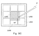
- a reception area UA may be expanded toward a touch position, a direction of shift, etc, instead of expanding to all directions. For example, when a first touch position TP is on a right lower portion of the reception area UA5 as shown in Fig. 9A , the area control unit 107 expands the reception area UA5 in the right-downward direction, i.e., only in the directions toward the reception areas UA6, UA9, and UA8, as shown in Fig. 9B . Then, when a second touch position TP touched in this state is expectedly shifted to the right-downward direction, the area control unit 107 further expands the reception area UA5 in the right-downward direction as shown in Fig. 9C . In this case too, even if a touch position TP is off the original reception area UA5 to fall on an edge of the reception area UA6, which is within the expanded reception area UA5, it is possible to determine that the key image K5 has been touched.
- reduction of a reception area may also be performed not only at one time, but in discrete gradation or continuous gradation.
- the embodiment described above has explained control for expansion, etc. of a reception area.
- the size of the key images, etc. which are the user interface items, may also be subjected to expansion, etc. to match the reception areas.
- the display control unit 101 may likewise expand a key image K corresponding to that area, which is one of the key images K (K1 to K9) displayed on the second display unit 19. That is, the display control unit 101 functions as a target image control unit, and expands a key image K corresponding to an expanded reception area UA to cover exactly the same range as the expanded reception area UA.
- key image display for a multi-tap text entry system may be changed in a manner to facilitate a user's text entry, based on the number of touching operations, the timing at which the first letter of a key returns as the target letter to be input after repetitive touching operations, etc. For example, when a predetermined number of continuous touching operations have been given and the first letter is the target letter to be input after going through a full round of the letters, these letters, which are assigned to one key image, may be rendered enterable from another key image.
- the display control unit 101 changes the content of the key array image KH. For example, as shown in Fig. 10B and Fig. 10C , all the letters assigned to the key image K5 may be displayed at the same time to enable a user to enter a desired letter directly.
- the display control unit 101 may change the display contents of the plurality of key images K arrayed around the key image K5 as shown in Fig. 10B and Fig. 10C .
- the process control unit 102 performs determination of a key image K that is given a touching operation by a long press, etc., based on a touch position, etc. supplied by the detecting unit 104, etc.
- the display control unit 101 having received a determination result from the process control unit 102, turns to function as the target image control unit, and displays the letters assigned to the key image that was given the long press, etc. by changing them to be the display contents of surrounding other key images.
- the process control unit 102 determines the letter corresponding to the display content of the key image that has just been given the touching operation, as the letter having input by the user. For example, when a touching operation is given to the key image K2 in the state of Fig. 10C , the process control unit 102 determines the input as a letter "NI". Then, when a touching operation is given again to the key image K5, the process control unit 102 determines the input as a letter "NA". It should be noted that not only a touching operation but any other may trigger determination of a letter that is input by a user.
- the letter corresponding to a key image that is dragged may be determined as an input.
- the process control unit 102 discriminates a key image from which a touch pen P (or a finger) is released after the display content is changed, and determines the letter corresponding to the display content of the discriminated key image as a letter that is input by the user. For example, when the touch pen P is dragged to the key image K4 and released therefrom in the state of Fig.
- the process control unit 102 determines a letter "NO" as an input.
- the process control unit 102 determines a letter "NA" as an input.
- Fig. 10B and Fig. 10C presented above are example key array images, to which the display content is changed when the key image K5 in the center is given a long press, etc., so different key array images will be displayed in accordance with the position, etc. of a key image K that is given a long press, etc.
- the display control unit 101 changes the display contents of a plurality of key images K that are arrayed in the vicinity of the key image K1 as shown in Fig. 11A and Fig. 11B .
- the display control unit 101 changes the display contents of a plurality of key images K that are arrayed in the vicinity of the key image K2 as shown in Fig. 12A and Fig. 12B .
- the key array image described above has been a case of nine key images K being arrayed, as an example.
- the number of key images K arrayed is not limited to nine, but may be arbitrarily changed.
- a key array image KH in which twenty-five key images K (K1 to K25) are arrayed, may be displayed.
- a plurality of different letters are assigned to each of the key images K7 to K9, K12 to K14, and K17 to K19, for example.
- the display control unit 101 displays the letters assigned to this key image by changing them to be the display contents of other key images that are arrayed in the vicinity, as well as the above. For example, when the key image K7 is given a long press, etc., the display control unit 101 changes the display contents of a plurality of key images K that area arrayed around the key image K7 as shown in Fig. 13B and Fig. 13C .
- a touching operation is a contact to the touch panel 20.
- the embodiment can also appropriately be applied to a case in which a release from a contacted state is detected as a touching operation. That is, a position of release may be seen as a touch position, which may be then checked with the reception areas UA as well as the above, and any reception area UA may be subjected to expansion, etc.
- an input reception device that processes a touch position at the time of release as an input can appropriately prevent an input failure in continuous touching operations.
- the present invention can provide an input reception device, an area control method, an information recording medium, and a program that can appropriately prevent an input failure in continuous touching operations.
Abstract
A display control unit (101) displays a key image, which serves as an operation target, etc. on a display unit. An area memory unit (103) stores a reception area (area information) corresponding to the displayed key image. A detecting unit (104) senses a user's touching operation and detects its touch position. A determining unit (105) makes determinations whether the detected touch position is within the range of the reception area stored in the area memory unit (103), etc. A time measuring unit (106) measures a time period that has elapsed since the touching operation. When a touching operation is detected, an area control unit (107) expands a reception area that includes the touch position to a predetermined range. Thereafter, the area control unit (107) reduces the expanded reception area to its original size when the time measuring unit (106) measures a predetermined time period.
Description
- The present invention relates to an input reception device, an area control method, an information recording medium, and a program that can appropriately prevent an input failure in continuous touching operations.
- Conventionally, touch panels have been used commonly as one kind of input device that receives an input operation from a user. Such a touch panel is disposed on the front face of a display unit such as a Liquid Crystal Display (LCD) and waits for a touching operation (a contact, etc.) to be given by a user's finger or a touch pen (a stylus or the like) in a state that the display unit displays a target image (e.g., a button image). When an area (a reception area) on the touch panel that corresponds to the button image is touched, the input device enters instruction information, etc. assigned to the touched button image.
Recently, compact devices such as portable game devices, mobile phones (portable terminals), etc. have come to carry a touch panel. In general, users hold such a compact device in one hand and give a touching operation to the touch panel by the other hand (a finger or a touch pen), often resulting in that the user's finger or the like shakes and misses the point. When giving a touching operation with a touch pen, users often let it slip on the touch panel to be out of position.
When a touching operation is given to an edge (boundary) of the button image on the touch panel, the finger or the like that has touched down might shake, coming into and out of the reception area repeatedly, raising a concern that determination of an input might run an intermittent repetition of ON and OFF (i.e., there occurs a chattering). - A disclosed technique for appropriately preventing occurrence of such a chattering detects any touch to the touch panel, and in response, expands the reception area (recognition area) of the touched button image within an extent that it does not overlap other reception areas to perform determination based on the position of the finger or the like when it is detached (released) from the touch panel and the expanded reception area (e.g., see Patent Literature 1).
- Patent Literature 1: Unexamined Japanese Patent Application KOKAI Publication No.
2006-133887 Fig. 5 ) - The technique of
Patent Literature 1 described above makes it possible to appropriately prevent occurrence of a chattering due to shakes of a finger or a touch pen while it is touching the touch panel (during a period from touch to release).
However, in a situation where touching operations are continuously given to the same place (i.e., a situation of repeating touch and release a plurality of times in a short period), a gradual shift of the position hit by the touching operations (the position to be touched) might entail. When it entails, the problem explained below, which has been verified to be unsolvable by the technique disclosed inPatent Literature 1, eventually occurs. - For example, mobile phones commonly employ an input system called multi-tap as their text entry system. This system assigns a plurality of letters to each key, and in response to each continuous press to the same key, switches among the target letters in order.
When implemented on a touch panel, such a multi-tap system displays a predetermined number of key images (e.g., images representing letter keys, etc.) on a display unit and lets a user touch a desired key image (to be more specific, a reception area on the touch panel). An actual scene of text entry will naturally include a situation
where the same key image is touched a plurality of times repetitively. - As such touching operations are repeated, a position touched might fall out of the key image (reception area), which renders the inputs to the key image canceled and un-entered, requiring the user to reconfirm the position that should be touched and restart the touching operations from scratch.
Further, limitations on size, resolution, etc. of a display unit often require the key images to be displayed with a considerably small interval between them (with virtually no space between them). In such a case, a position touched in continuous touching operations that falls out of an intended key image constitutes an input to another key image, leading to a problem of an erroneous input. - Furthermore, apart from such text entry cases as above, various other situations where touching operations are repeated to the same target possibly exist. For example, one such situation is where a plurality of command images on a portable game device that are used for instructing a character to do some actions, etc. are displayed and inputs to the command images via a touch panel are received.
Such a case can also include a scene in which a player has to continuously instruct his/her character to do the same action, bringing about a situation where a touching operation is performed on the same command image a plurality of times. Then, a position touched in the repetitive touching operations might be off the intended command image and likewise produce invalidation of an action instruction or an erroneous input of another kind of action instruction. - Hence, there has been a demand for a technique that prevents input failures, such as invalidation (un-entry) or erroneous input of a touching operation in a situation where touching operations are repeated to the same target.
- The present invention was made to solve these problems and an object of the present invention is to provide an input reception device, an area control method, an information recording medium, and a program that can appropriately prevent an input failure in continuous touching operations.
- An input reception device according to a first aspect of the present invention is an input reception device that receives an input via a touch panel disposed on a display unit, and includes an area memory unit, a detecting unit, a determining unit, and an area control unit.
- The area memory unit stores area information about an area on the touch panel, which is a variable reception area corresponding to a predetermined target image displayed on the display unit. The detecting unit detects, in response to a touching operation to the touch panel, its touch position. The determining unit determines whether the detected touch position is within or outside the range of the stored reception area. The area control unit sets a reception area that matches the display area of the target image in the area memory unit; when a touch position is detected and determined to be within the range, expands the reception area to a predetermined range; and when a touching operation is not given to the expanded reception area within a predetermined time period, reduces the expanded reception area back to the reception area before being expanded.
- That is, when the detecting unit detects a touching operation, the determining unit specifies its touch position and determines that the touch position is within the reception area of a given target image. For example, when the touch position is within the reception area of a target image A, the area control unit expands the reception area of the target image A. When a touching operation is to be given continuously to the target image A in this state, the detecting unit shall detect this continuous touching operation before a predetermined time period (e.g., 0.3 second) elapses. That is, the determining unit shall determine whether the next touch position is within or outside the range of the expanded reception area of the target image A.
Hence, even if the touch position falls a bit out of the display area of the target image A but lands within the expanded reception area, it is possible to determine that the touching operation has been directed to the target image A.
On the other hand, when a touching operation is to be given to a target image B after expansion of the reception area of the target image A, the time elapsed between the expansion and the touch is longer than the predetermined time period because of including moving a touch pen or the like. The expanded reception area of the target image A has already got back to its original size matching the display area. Hence, even if the target image B exists immediately next to the target image A, it is possible to determine in the reception area of the target image B that the touching operation has been directed to the target image B. Accordingly, it is possible to appropriately prevent an input failure in continuous touching operations. - An input reception device according to a second aspect of the present invention is an input reception device that receives an input via a touch panel disposed on a display unit, and includes a display control unit, an area memory unit, a detecting unit, a determining unit, a time measuring unit, and an area control unit.
- First, the display control unit displays a target image, which serves as an operation target, on the display unit. The area memory unit stores area information about an area on the touch panel, which is a variable reception area corresponding to the displayed target image. In response to a touching operation, including a contact, to the touch panel, the detecting unit detects its touch position.
- The determining unit determines whether a detected touch position is within or outside the range of a stored reception area. The time measuring unit measures a time period that has elapsed since a touching operation. The area control unit sets a first reception area that matches the display area of the target image in the area memory unit; when a touch position is detected and determined to be within the range, expands the first reception area to a second reception area that covers a larger range than the first reception area; and when a touching operation is not given to the second reception area until the measured time period becomes equal to a predetermined time period, reduces the second reception area to the first reception area.
- That is, when the detecting unit detects a touching operation, the determining unit specifies its touch position and determines it to be within the range of the first reception area of a given target image. Then, the area control unit expands the reception area of that target image to a second reception area, and the time measuring unit starts measuring a time period that has elapsed since the touching operation. When a touching operation is to be given continuously in this state, the detecting unit shall detect another touching operation before the time period measured by the time measuring unit becomes equal to a predetermined time period (e.g., 0.3 second). That is, the determining unit shall determine whether the next touch position is within or outside the range of the second reception area to which the first reception area is expanded.
Hence, even if the touch position falls a bit out of the display area of the target image but lands within the second reception area, it is possible to determine that the touching operation has been directed to that target image.
On the other hand, a touching operation that is to be given, after the reception area of the current target image was expanded to the second reception area, to another target image than this target image will let the time measuring unit measure a time period that is longer than the predetermined time period because of including moving a touch pen or the like. The reception area expanded to the second reception area has already got back to the original first reception area. Hence, even if this other target image exists immediately next to the former target image, it is possible to determine in the first reception area of this another target image that the touching operation has been directed to this another target image.
Accordingly, it is possible to appropriately prevent an input failure in continuous touching operations. - The area control unit may expand the reception area by gradually changing at least one of its shape and its size based on the number of touching operations.
In this case, expansion, etc. of the reception area is along with an increase in the number of touching operations, bringing more efficiency in prevention of input failure, etc. - The area control unit may expand the reception area toward a predetermined direction based on a change of touch positions.
In this case, for example, the reception area will be expanded in a direction in which touching operations of a user are shifted, bringing more efficiency in prevention of input failure, etc. - The input reception device may further include a target image control unit that expands or reduces the target image to the size of a corresponding reception area, which is expanded or reduced by the area control unit.
In this case, a target image corresponding to a reception area and having the same size as the reception area is also subjected to expansion, etc. to match the size of the reception area, making it possible to visually recognize that an input failure, etc. is prevented. - The display unit may display thereon a predetermined number of the target image in an array.
The input reception device may further include a target image control unit that, after a predetermined touching operation is given, changes the display contents of a plurality of target images that are arrayed in the vicinity of the target image that is given that touching operation. For example, if the key image display for multi-tap text entry is changed when a long press or the like is given or when the number of touching operations reaches a predetermined number (e.g., two), the text entry will be more facilitated. - Each of the target images may be in advance assigned a plurality of different letters.
The target image control unit may change the respective letters assigned to the target image that is given a touching operation, such that the letters become the display contents of the target images arrayed in the vicinity of the target image given the touching operation respectively. For example, if the respective letters that are assigned to a target image that is given a touching operation are displayed in the vicinity of that target image, text entry will be more efficient in a multi-tap system. - An input reception device according to a third aspect of the present invention is an input reception device that receives an input via a touch panel disposed on a display unit, and includes a display control unit, a determining unit, and a target image control unit.
- First, the display control unit displays an array of a predetermined number of target images (e.g., key images), each of which is in advance assigned a plurality of different letters, on the display unit. The determining unit detects a touching operation including a contact that is given to the touch panel, and determines any of the target images that is given the touching operation. The target image control unit changes, after a predetermined touching operation (e.g., a long press, etc.) is given, the display contents of the target images that are arrayed in the vicinity of the target image that is given that touching operation, to the letters assigned to the target image given the touching operation respectively.
- That is, the target image control unit changes the display contents of the key images that are arrayed in the vicinity of the key image that is given a long press, etc. to the letters assigned to the key image that is given the long press, etc.
This makes the letters assigned to the key image given the long press, etc. be displayed at the same time on the key images that exist in the vicinity, making it possible for a user to more efficiently enter a text. - An area control method according to a fourth aspect of the present invention is an area control method of an input reception device that includes a memory unit and receives an input via a touch panel disposed on a display unit, and the method includes a detecting step, a determining step, and an area controlling step.
- The memory unit stores area information about an area on the touch panel, which is a variable reception area corresponding to a predetermined target image displayed on the display unit. At the detecting step, in response to a touching operation to the touch panel, its touch position is detected. At the determining step, it is determined whether a detected touch position is within or outside the range of a reception area stored in the memory unit. At the area controlling step, a reception area that, in its initial state, matches the display area of the target image is set in the memory unit. Also, when a touch position is detected and determined to be within the range, the reception area is expanded to a predetermined range, and when a touching operation is not given to the expanded reception area within a predetermined time period, the expanded reception area is reduced back to the reception area before being expanded.
- That is, when a touching operation is detected at the detecting step, its touch position is specified at the determining step and determined to be within a reception area of a given target image. For example, when the touch position is within the reception area of a target image A, the reception area of the target image A is expanded at the area controlling step. When a touching operation is to be given continuously to the target image A in this state, this continuous touching operation shall be detected at the detecting step before a predetermined time period (e.g., 0.3 second) elapses. That is, it shall be determined at the determining step whether the next touch position is within or outside the range of the expanded reception area of the target image A.
Hence, even if the touch position falls a bit out of the display area of the target image A but lands within the expanded reception area, it is possible to determine that the touching operation has been directed to the target image A.
On the other hand, when a touching operation is to be given to a target image B after expansion of the reception area of the target image A, the time elapsed between the expansion and the touch is longer than the predetermined time period because of including moving a touch pen or the like. The expanded reception area of the target image A has already got back to its original size matching the display area. Hence, even if the target image B exists immediately next to the target image A, it is possible to determine in the reception area of the target image B that the touching operation has been directed to the target image B. Accordingly, it is possible to appropriately prevent an input failure in continuous touching operations. - An information recording medium according to a fifth aspect of the present invention stores a program for controlling a computer (including an electronic device) to function as the input reception device described above.
- A program according to a sixth aspect of the present invention controls a computer (including an electronic device) to function as the input reception device described above.
- This program may be recorded on a computer-readable information recording medium such as a compact disk, a flexible disk, a hard disk, a magneto-optical disk, a digital video disk, a magnetic tape, a semiconductor memory, etc.
- The program may be distributed or sold through a computer communication network independently from a computer on which the program is executed. The information recording medium described above may be distributed or sold independently from the computer.
- In accordance with the present invention, it is possible to appropriately prevent an input failure in continuous touching operations.
-
- [
Fig. 1] Fig. 1 is an exemplary diagram showing appearance of a game device according to an embodiment of the present invention. - [
Fig. 2] Fig. 2 is an exemplary diagram showing a schematic configuration of the game device according to the embodiment. - [
Fig. 3] Fig. 3 is an exemplary diagram showing a schematic configuration of an input reception device according to the embodiment. - [
Fig. 4A] Fig. 4A is an exemplary diagram showing an example of key array image (or its respective key images) displayed. - [
Fig. 4B] Fig. 4B is an exemplary diagram explaining reception areas corresponding to the key images respectively. - [
Fig. 5A] Fig. 5A is an exemplary diagram explaining the reception areas. - [
Fig. 5B] Fig. 5B is an exemplary diagram explaining a reception area that is expanded. - [
Fig. 6] Fig. 6 is a flowchart showing the flow of an area control process according to the embodiment. - [
Fig. 7A] Fig. 7A is an exemplary diagram explaining timings of touching operations. - [
Fig. 7B] Fig. 7B is an exemplary diagram explaining how the reception areas are controlled. - [
Fig. 7C] Fig. 7C is an exemplary diagram explaining how the reception areas are controlled. - [
Fig. 8A] Fig. 8A is an exemplary diagram explaining how a reception area is expanded gradually. - [
Fig. 8B] Fig. 8B is an exemplary diagram explaining how a reception area is expanded gradually. - [
Fig. 8C] Fig. 8C is an exemplary diagram explaining how a reception area is expanded gradually. - [
Fig. 9A] Fig. 9A is an exemplary diagram explaining how a reception area is expanded in a predetermined direction. - [
Fig. 9B] Fig. 9B is an exemplary diagram explaining how a reception area is expanded in a predetermined direction. - [
Fig. 9C] Fig. 9C is an exemplary diagram explaining how a reception area is expanded in a predetermined direction. - [
Fig. 10A] Fig. 10A is an exemplary diagram explaining how the display content of a key array image (or its respective key images) is changed. - [
Fig. 10B] Fig. 10B is an exemplary diagram explaining how the display content of a key array image is changed. - [
Fig. 10C] Fig. 10C is an exemplary diagram explaining how the display content of a key array image is changed. - [
Fig. 11A] Fig. 11A is an exemplary diagram explaining how the display content of a key array image is changed in a different way. - [
Fig. 11B] Fig. 11B is an exemplary diagram explaining how the display content of a key array image is changed in a different way. - [
Fig. 12A] Fig. 12A is an exemplary diagram explaining how the display content of a key array image is changed in a different way. - [
Fig. 12B] Fig. 12B is an exemplary diagram explaining how the display content of a key array image is changed in a different way. - [
Fig. 13A] Fig. 13A is an exemplary diagram explaining how the display content of a different type of key array image (or its respective key images) is changed. - [
Fig. 13B] Fig. 13B is an exemplary diagram explaining how the display content of the different type of key array image is changed. - [
Fig. 13C] Fig. 13C is an exemplary diagram explaining how the display content of the different type of key array image is changed. -
- 1
- game device
- 10
- process control unit
- 11
- connector
- 12
- cartridge
- 13
- wireless communication unit
- 14
- communication controller
- 15
- sound amplifier
- 16
- speaker
- 17
- operation keys
- 18
- first display unit
- 19
- second display unit
- 20
- touch panel
- 100
- input reception device
- 101
- display control unit
- 102
- process control unit
- 103
- area memory unit
- 104
- detecting unit
- 105
- determining unit
- 106
- time measuring unit
- 107
- area control unit
- Embodiments of the present invention will be described below. For ease of understanding, the embodiments below of the present invention are described as applications to portable game devices (game machines). However, the present invention may be similarly applied to information processing devices, such as various computers, PDAs, or mobile phones. In other words, the embodiments described below are provided to give explanations, but not to limit the scope of the present invention. Therefore, those skilled in the art can adopt embodiments in which some or all of the elements herein have been replaced with respective equivalents, and such embodiments are also to be included within the scope of the present invention.
-
Fig. 1 is an exemplary diagram showing appearance of a typical game device on which an input reception device according to the embodiments of the present invention is realized. As illustrated, thegame device 1 characteristically includes afirst display unit 18 and asecond display unit 19, which each can display a predetermined image. Atouch panel 20 is disposed on the front face of thesecond display unit 19. -
Fig. 2 is an exemplary diagram showing a schematic configuration of the game device ofFig. 1 . The following explanation will be given with reference toFig. 2 . - The
game device 1 includes aprocess control unit 10, aconnector 11, acartridge 12, awireless communication unit 13, acommunication controller 14, asound amplifier 15, aspeaker 16,operation keys 17, thefirst display unit 18, thesecond display unit 19, and atouch panel 20. - The
process control unit 10 includes a Central Processing Unit (CPU)core 10a, animage processing unit 10b, aclock circuit 10c, a Video Random Access Memory (VRAM) 10d, a Work RAM (WRAM) 10e, a Liquid Crystal Display (LCD)controller 10f, and atouch panel controller 10g.
The process control unit further - The
CPU core 10a controls the operation of thewhole game device 1, being connected to each component to exchange control signals and data with it. Specifically, with thecartridge 12 inserted to theconnector 11, theCPU core 10a reads out programs and data stored in a Read Only Memory (ROM) 12a in thecartridge 12 and performs a predetermined process. - The
image processing unit 10b applies some process to the data read out from theROM 12a in thecartridge 12 or to the data processed by theCPU core 10a and stores it in theVRAM 10d. - The
clock circuit 10c serves to measure various kinds of time periods (or times of day). It checks the current time of day set in thegame device 1 or measures the time period that is needed during the game. - The
VRAM 10d is a memory that stores display information - i.e., image information processed by theimage processing unit 10b, etc.
TheWRAM 10e stores work data, etc. that are necessary for theCPU core 10a to perform various processes in accordance with a program. - The
LCD controller 10f controls thefirst display unit 18 and thesecond display unit 19 to display a predetermined display image. For example, theLCD controller 1 0f converts image information stored in theVRAM 10d into display signals at predetermined synchronization timings and outputs them to thefirst display unit 18. TheLCD controller 10f displays predetermined instruction icons, etc. on thesecond display unit 19. - The
touch panel controller 10g detects a contact (touch) of a touch pen or a user's finger to thetouch panel 20. For example, in a state that the predetermined instruction icons, etc. are displayed on thesecond display unit 19, thetouch panel controller 10g detects a touch to or a release from thetouch panel 20, the position of the touch or the release, etc. - The
connector 11 is a terminal that can detachably connect with thecartridge 12, and when connected with thecartridge 12, exchange predetermined data with thecartridge 12. - The
cartridge 12 includes theROM 12a and a Random Access Memory (RAM) 12b.
TheROM 12a stores a program for realizing a game and image data, sound data, etc. that accompany the game.
TheRAM 12b stores various data representing progress statuses of the game, etc. - The
wireless communication unit 13 is a unit that wirelessly communicates with thewireless communication unit 13 of anothergame device 1, and exchanges predetermined data with it via an unillustrated antenna (built-in antenna or the like).
Thewireless communication unit 13 is also capable of wirelessly communicating with a predetermined wireless access point. Thewireless communication unit 13 is assigned a unique Media Access Control (MAC) address. - The
communication controller 14 controls thewireless communication unit 13 and thereby intermediates between theprocess control unit 10 and its counterpart in anothergame device 1 in accordance with a predetermined protocol for them to perform wireless communication.
When thegame device 1 connects to the Internet via a nearby wireless access point or the like, thecommunication controller 14 intermediates between theprocess control unit 10 and the wireless access point or the like in accordance with a wireless LAN protocol for them to perform wireless communication. - The
sound amplifier 15 amplifies a sound signal generated by theprocess control unit 10 and supplies it to thespeaker 16.
Thespeaker 16 is constituted by, for example, a stereo speaker or the like, and outputs a predetermined musical sound, sound effects, etc. in accordance with the sound signal amplified by thesound amplifier 15. - The
operation keys 17 include a plurality of key switches, etc. that are properly arranged on thegame device 1 in an array, and receive a predetermined instruction input in response to a user's operation. - The
first display unit 18 and thesecond display unit 19 are constituted by a LCD or the like and display an appropriate game image, etc. under the control of theLCD controller 10f.
Thesecond display unit 19 displays instruction icons, etc. via which a user touches thetouch panel 20 to input an operation instruction. - The
touch panel 20 is disposed on the front face of thesecond display unit 19, and receives an input that is given by a contact thereto of a touch pen or a user's finger.
Thetouch panel 20 is constituted by, for example, a pressure-sensitive touch sensor panel or the like, senses a pressure of a touch pen or the like to detect a touching operation such as a contact, its position (touch position), etc.
Otherwise, thetouch panel 20 may detect a contact of a user's finger or the like based on a change in capacitance, etc. -
Fig. 3 is an exemplary diagram showing a schematic configuration of theinput reception device 100 according to the present embodiment. The following explanation will be given with reference toFig. 3 .
Theinput reception device 100 includes adisplay control unit 101, aprocess control unit 102, anarea memory unit 103, a detectingunit 104, a determiningunit 105, atime measuring unit 106, and anarea control unit 107. - The
display control unit 101 displays various images on the display unit (thefirst display unit 18 or thesecond display unit 19 described above).
For example, thedisplay control unit 101 displays a target image, which serves as an operation target, on thesecond display unit 19 on which thetouch panel 20 is disposed. Specifically, thedisplay control unit 101 displays a key array image KH as shown inFig. 4A on thesecond display unit 19.
For example, the key array image KH includes nine key images K (K1 to K9), which are arrayed with a relatively small interval between them. Each key image K is assigned a plurality of letters (to be more specific, a plurality of letter codes) in accordance with a multi-tap system. - For example, the key image K1 is assigned ten letters, namely "A", "I", "U", "E", "O", "a", "i", "u", "e", and "o" (which is an example case of a Japanese text input mode). When the key image K1 (or its corresponding reception area on the
touch panel 20, to be more specific) is touched, the letters to be entered switch in order of, for example, "A"→"I"→"U", ....
When it switches to the last letter "o", the order returns and switches to the first letter "A". That is, the ten letters sequentially switch in circles.
Theimage processing unit 10b and theLCD controller 10f described above can function as thedisplay control unit 101. - Returning to
Fig. 3 , theprocess control unit 102 controls theinput reception device 100 as a whole.
For example, for a character's name, a user's nickname, etc. to be input, theprocess control unit 102 controls thedisplay control unit 101 to have the above-described key array image KH, etc., displayed. In this state, theprocess control unit 102 acquires letters (letter string) input by the user, in accordance with a result of input determination made by the determiningunit 105.
TheCPU core 10a described above can function as theprocess control unit 102. - The
area memory unit 103 stores reception areas (or range information or the like defining the areas) on thetouch panel 20 that are set in correspondence to the key array image KH (or the respective key images K) displayed on thesecond display unit 19. The reception areas are where determination of whether to enter an input given to each key image K (or whether an input is effective) is performed.
Specifically, as shown inFig. 4B , thearea memory unit 103 stores nine reception areas UA (UA1 to UA9) corresponding to the key images K (display areas) ofFig. 4A described above.Fig. 4B shows the sizes of the reception areas UA in their initial state (or standby state), in which they perfectly align with the key images K ofFig. 4A respectively.
In this state, when, for example, a touch pen touches an edge of the key image K5 (i.e., when a touching operation is given thereto), the determiningunit 105, etc., which are to be described later, will let a letter assigned to the key image K5 be entered, as this position (touch position) is included in the reception area UA5.
On the other hand, when the key image K5 is missed but the key image K6 is touched on its edge, a letter assigned to the key image K6 will be entered because the position is included in the reception area UA6. - The
area control unit 107 manages each reception area UA in a size-variable manner. As will be described in detail later, under some circumstance, thearea control unit 107 has to expand any of the reception areas UA up to a predetermined range. Under such a circumstance, thearea memory unit 103 shall store the reception areas UA including the expanded one.
TheWRAM 10e described above can function as thearea memory unit 103. - The detecting
unit 104 senses occurrence of a touch to and a release from thetouch panel 20 and detects their positions (or their positions on the touch panel in coordinate representation, etc.) based on some information (a signal or the like) acquired from thetouch panel 20.
For example, in response to a touching operation (a contact, etc.) to thetouch panel 20, the detectingunit 104 detects the touch position (the position of contact, etc.) Then, the detectingunit 104 supplies the detected touch position to the determiningunit 105, thetime measuring unit 106, etc.
Thetouch panel controller 10g described above can function as the detectingunit 104. - In response to a touching operation to the
touch panel 20, the determiningunit 105 determines where the input is given (and whether to enter the input, etc.) by using the information stored in thearea memory unit 103.
For example, when supplied with a touch position from the detectingunit 104, the determiningunit 105 determines whether the touch position is included in any of the reception areas UA, etc.
Specifically, the determiningunit 105 determines whether or not a touch position TP touched by a touch pen P is included in the reception areas UA1 to UA9, as shown inFig. 5A . In the case ofFig. 5A , the determiningunit 105 determines that the touch position TP is included in the reception area UA5, i.e., that the corresponding key image K5 has been touched.
As will be described in detail later, when any reception area UA is expanded as shown inFig. 5B , the determiningunit 105 makes determinations by using the expanded reception area UA (e.g., the reception area UA5).
TheCPU core 10a described above can function as the determiningunit 105. - The
time measuring unit 106 measures a predetermined time period in response to a touching operation to thetouch panel 20.
For example, when supplied with a touch position from the detectingunit 104 in response to a touch to thetouch panel 20, thetime measuring unit 106 starts measuring the lapse of time from the time of the detection. This time period is measured to be compared with a standard time interval between continuous touching operations (i.e., a time period between the most recent touching operation and the touching operation immediately before the most recent one).
Specifically, suppose it has been experimentally or in any manner found that a time interval between touching operations that are given in a situation of repeating touching operations to the same key image K is, for example, 0.3 second at a maximum. Under this condition, when thetime measuring unit 106 starts measuring an elapsed time period in response to an initial touching operation and within 0.3 second thereafter detects another touching operation, it is possible to determine that these touching operations are continuous (or that before the latter one, a touching operation has been given to the same key image K at least once).
On the other hand, a touching operation, which is to be given to a key image that is different from the one that is touched by a previous touching operation, needs an extra time period for a touch pen or the like to be moved or for some other reasons. A time period longer than 0.3 second (e.g., a time period of approximately 1 second) is needed therefor even if the user gives quick touching operations. Therefore, when the next touching operation is detected after 0.3 second has elapsed since the start of measurement of the time period by thetime measuring unit 106, it is possible to determine that the touching operations are not continuous (or highly unlikely to be continuous).
Theclock circuit 10c described above can function as thetime measuring unit 106. - The
area control unit 107 manages the size, etc. of each reception area UA stored in thearea memory unit 103 in an appropriate manner.
For example, when the determiningunit 105 determines that a touch position is included in any of the reception areas UA, thearea control unit 107 expands that reception area UA to a predetermined range.
Specifically, when a touch position TP is determined to be included in the reception area UA5 as shown inFig. 5A , thearea control unit 107 expands the reception area UA5 as shown inFig. 5B . That is, thearea control unit 107 expands the reception area UA5 to such a range that overlaps, at a predetermined ratio, other surrounding reception areas UA.
In the state that the reception area UA5 is expanded, for example, during continuous touching operations by the user, it is possible to determine that the key image K5 (or the reception area UA5 before being expanded) has been entered, as long as the touched position is not greatly off the key image K5 (unless the touched position falls out of the reception area UA5 after being expanded). - When an elapsed time period that is measured by the
time measuring unit 106 becomes as long as a predetermined time period (e.g., 0.3 second as above), thearea control unit 107 reduces the expanded reception area UA5 to its original size.
That is, because there will be no (or highly unlikely no) continuous touching operation given after 0.3 second has elapsed, thearea control unit 107 reduces the expanded reception area UA5 ofFig. 5B to its original size as shown inFig. 5A . Therefore, in a touching operation directed to another adjoining key image K thereafter, a touch position is within bounds of its corresponding reception area UA, making this key image K be entered, not the key image K5.
TheCPU core 10a described above can function as thearea control unit 107. -
Fig. 6 is a flowchart showing the flow of an area control process performed by theinput reception device 100 having the configuration described above. The following explanation will be given with reference toFig. 6 . The area control process will be started in a state that, for example, the key array image KH (or its respective key images K) shown inFig. 4A is/are displayed on thesecond display unit 19. In the initial state, each reception area UA stored in thearea memory unit 103 has the size of its corresponding key image K, as shown inFig. 4B . - First, the
input reception device 100 determines whether or not a touching operation has been detected (step S201). That is, the detectingunit 104 determines whether it has sensed a touching operation that starts by a contact to the touch panel and ends by a release from the touch panel. - Upon determination that no touching operation has been detected (step S201; No), the
input reception device 100 advances the flow to step S207 described later.
On the other hand, upon determination that a touching operation has been detected (step S201; Yes), theinput reception device 100 acquires the touch position (step S202). That is, in response to sensing a touching operation, the detectingunit 104 detects the touch position, which is the position of contact. - The
input reception device 100 determines whether or not the detected touch position is included in any of the reception areas (step S203). That is, the determiningunit 105 determines to which image key the input has been given (or whether or not to enter the input), etc. by using information about the reception areas stored at that time in thearea memory unit 103.
That is, if it is in the initial state, the determiningunit 105 compares such reception areas UA as shown inFig. 4B presented above, none of which is expanded, with the touch position to determine to which image key K the input has been given, etc.
If it is in a state that any of the reception areas UA is expanded, the determiningunit 105 compares such reception areas UA as shown inFig. 5B presented above, which include the expanded one, with the touch position to make determinations. - Upon determination that the touch position is not included in any of the reception areas (step S203; No), the
input reception device 100 returns the flow to step S201 described above.
On the other hand, upon determination that the touch position is included in any of the reception areas (step S203; Yes), theinput reception device 100 specifies the key image to enter a corresponding letter (step S204).
That is, theprocess control unit 102 specifies any key image K ofFig. 4A that corresponds to the reception area UA in which the touch position is included, and enters a letter corresponding to the specified key image K. - The
input reception device 100 expands the reception area in which the touch position is included (step S205). That is, thearea control unit 107 expands the reception area UA shown inFig. 5A in which the touch position TP is included (i.e., the reception area UA5 in the case ofFig. 5A ) to a range where it overlaps, at a predetermined ratio, other surrounding reception areas UA as shown inFig. 5B .
When a predetermined time period (e.g., 0.3 second) has not yet elapsed since the expansion by the last touching operation, thearea control unit 107 keeps this reception area as is because it has been already expanded. - The
input reception device 100 starts measuring an elapsed time period (step S206). That is, thetime measuring unit 106 starts measuring a time period that has elapsed since this point in time.
When thetime measuring unit 106 has already started measuring an elapsed time period (i.e., when 0.3 second has not yet elapsed since the last touching operation), thetime measuring unit 106 resets the time period that has been measured to zero to restart measuring an elapsed time period.
Then, theinput reception device 100 returns the flow to step S201 described above. - Upon determination at step S201 described above that no touching operation has been detected (step S201; No), the
input reception device 100 determines whether or not an elapsed time period is currently being measured (step S207).
That is, theinput reception device 100 determines whether thetime measuring unit 106 is currently measuring an elapsed time period. Upon determination that an elapsed time period is not currently being measured (step S207; No), theinput reception device 100 returns the flow to step S201 described above. - On the other hand, upon determination that an elapsed time period is currently being measured (step S207; Yes), the
input reception device 100 determines whether or not the elapsed time period measured has exceeded 0.3 second (example) (step S208).
That is, when it has been experimentally or in any manner found that a time interval between continuous touching operations given to the same target image is 0.3 second, theinput reception device 100 determines whether or not the elapsed time period has exceeded the found value of 0.3 second.
Then, upon determination that the elapsed time period has not become longer than 0.3 second (step S208; No), theinput reception device 100 returns the flow to step S201 described above. - On the other hand, upon determination that the elapsed time period has exceeded than 0.3 second (step S208; Yes), the
input reception device 100 reduces the expanded reception area to its original size (step S209). That is, here, it is possible to determine that continuous touching operations have not been given because there has been a substantial time interval taken between touching operations. Hence, the reception area should be reduced to its original size. - The
input reception device 100 stops measuring the elapsed time period (step S210). That is, theinput reception device 100 stops thetime measuring unit 106 from measuring.
Then, theinput reception device 100 returns the flow to step S201 described above. - This area control process can prevent input failures such as invalidation (non-entry) or erroneous input of a touching operation in a situation where touching operations are repeated to the same target.
- That is, as shown in
Fig. 7A , upon detection of a first touching operation tp1 by the detectingunit 104, the determiningunit 105 specifies the touch position and determines in which reception area the touch position is included, etc. Here, when it is the reception area UA5 that includes the touch position, thearea control unit 107 expands the reception area UA5 as shown inFig. 7B . Along with this, thetime measuring unit 106 starts measuring an elapsed time period. - When there is to be given a continuous touching operation to the same target in this state, the detecting
unit 104 shall detect a second touching operation tp2 after a time period tm1, which is shorter than 0.3 second, as shown inFig. 7A . Then, the determiningunit 105 specifies the touch position of the second touching operation tp2 and determines in which reception area it is included, etc. Here, attending first to the reception area UA5 that has been expanded as shown inFig. 7B , the determiningunit 105 shall determine whether the touch position is included in the range of the reception area UA5 or the others, etc.
Hence, even when the touch position TP has fallen out of the former reception area UA5 to an edge of the reception area UA6, which is within the expanded reception area UA5 as shown inFig. 7B , it is possible to determine that the key image K5 has been touched.
Thearea control unit 107 keeps the expanded reception area UA5 shown inFig. 7B as is, and thetime measuring unit 106 restarts measuring an elapsed time period after being reset to zero. - When another continuous touching operation is to be given to the same target in this state, the detecting
unit 104 shall detect a third touching operation tp3 after a time period tm2, which is shorter than 0.3 second as shown inFig. 7A . Then, likewise, the determiningunit 105 determines whether the touch position is included in the range of the reception area UA5 or the others, etc.
In this case too, even if the touch position TP has fallen out of the original reception area UA5, it is possible to determine that the key image K5 has been touched as long as the touch position TP is within the expanded reception area UA5.
Thearea control unit 107 keeps the expanded reception area UA5 as is, and thetime measuring unit 106 restarts measuring an elapsed time period after being reset to zero. - When a touching operation is to be given to another target in this state, the detecting
unit 104 shall detect a fourth touching operation tp4 after a time period tm3, which is longer than 0.3 second, as shown inFig. 7A .
During this time period tm3, thearea control unit 107 shall reduce the expanded reception area UA5 to its original size as shown inFig. 7C , at a timing tov at which 0.3 second elapses. - In this case, since the reception area UA5 has regained its original size, for example, even a touch position TP that is in an edge portion of the reception area UA8 as shown in
Fig. 7C can be normally determined to be of a touching operation to the key image K8. - Accordingly, even if a position that is touched in repetitive touching operations to the same target (key image) is off the target, the corresponding reception area that is appropriately expanded can prevent the input from being invalidated or from being erroneously entered as another kind of input.
As a touching operation is to be given to another target (another key image), a predetermined time period (e.g., 0.3 second) has been exceeded because of including moving a touch pen or the like. The expanded reception area has its size reduced to its original. Hence, even if this other key image is located immediately next to the former key image, it is possible to determine in the reception area of this key image that the touching operation was given to this key image.
Hence, it is possible to appropriately prevent an input failure in continuous touching operations. - The embodiment described above has explained expansion of a reception area, wherein the reception area is expanded to a predetermined range at one time (in one stroke).
However, the manner of controlling expansion of a reception area is not limited to this but may be appropriately modified.
For example, in accordance with the number of continuous touching operations, the range to which a reception area is expanded may be enlarged in a discrete gradation manner or in a continuous gradation manner. - Specifically, when the range to which a reception area UA is expanded is gradated in three stages, the
area control unit 107 expands the reception area UA slightly at the first stage as shown inFig. 8A , and to an even larger range at the second stage as shown inFig. 8B . Then, at the third stage, thearea control unit 107 expands the reception area UA to its maximum as shown inFig. 8C .
As above, by expanding the reception area UA largely in accordance with the number of continuous touching operations, it is possible to appropriately deal with gradual shift of a touch position. - A reception area UA may be expanded toward a touch position, a direction of shift, etc, instead of expanding to all directions.
For example, when a first touch position TP is on a right lower portion of the reception area UA5 as shown inFig. 9A , thearea control unit 107 expands the reception area UA5 in the right-downward direction, i.e., only in the directions toward the reception areas UA6, UA9, and UA8, as shown inFig. 9B .
Then, when a second touch position TP touched in this state is expectedly shifted to the right-downward direction, thearea control unit 107 further expands the reception area UA5 in the right-downward direction as shown inFig. 9C .
In this case too, even if a touch position TP is off the original reception area UA5 to fall on an edge of the reception area UA6, which is within the expanded reception area UA5, it is possible to determine that the key image K5 has been touched. - Further, reduction of a reception area may also be performed not only at one time, but in discrete gradation or continuous gradation.
- The embodiment described above has explained control for expansion, etc. of a reception area. Likewise, the size of the key images, etc., which are the user interface items, may also be subjected to expansion, etc. to match the reception areas.
For example, in response to that thearea control unit 107 expands a given reception area UA, thedisplay control unit 101 may likewise expand a key image K corresponding to that area, which is one of the key images K (K1 to K9) displayed on thesecond display unit 19. That is, thedisplay control unit 101 functions as a target image control unit, and expands a key image K corresponding to an expanded reception area UA to cover exactly the same range as the expanded reception area UA.
Further, key image display for a multi-tap text entry system may be changed in a manner to facilitate a user's text entry, based on the number of touching operations, the timing at which the first letter of a key returns as the target letter to be input after repetitive touching operations, etc.
For example, when a predetermined number of continuous touching operations have been given and the first letter is the target letter to be input after going through a full round of the letters, these letters, which are assigned to one key image, may be rendered enterable from another key image. - Specifically, when a key array image KH shown in
Fig. 10A is displayed on thesecond display unit 19, touching operations are continuously given to the key image K5 in this state. After one full round of the letters is completed as "NA"→"NI"→"NU"→"NE"→ "NO"→"NA" (each representing a monosyllabic letter in Japanese), thedisplay control unit 101 changes the content of the key array image KH.
For example, as shown inFig. 10B and Fig. 10C , all the letters assigned to the key image K5 may be displayed at the same time to enable a user to enter a desired letter directly.
What is assumed here is that when a user tries to input one of the letters assigned to the key image K5, the user might overlook that very letter and have to wait one more round. Hence, displaying all the letters at one time to enable a direct input is more efficient and easier for the user. That is, when a predetermined touching operation is given to the key image K5, the key image display may be changed as shown inFig. 10B and Fig. 10C immediately, to make letter input easier for the user. For example, when a long press (i.e., letting a predetermined time period elapse while keeping a key touched) is given to the key image K5, or when a predetermined number (e.g., two) of touching operations are given to the key image K5, thedisplay control unit 101 may change the display contents of the plurality of key images K arrayed around the key image K5 as shown inFig. 10B and Fig. 10C . Note that theprocess control unit 102 performs determination of a key image K that is given a touching operation by a long press, etc., based on a touch position, etc. supplied by the detectingunit 104, etc.
Then, thedisplay control unit 101, having received a determination result from theprocess control unit 102, turns to function as the target image control unit, and displays the letters assigned to the key image that was given the long press, etc. by changing them to be the display contents of surrounding other key images. - When a touching operation is given in this state, in which the changed display content of each surrounding key image is displayed, the
process control unit 102 determines the letter corresponding to the display content of the key image that has just been given the touching operation, as the letter having input by the user. For example, when a touching operation is given to the key image K2 in the state ofFig. 10C , theprocess control unit 102 determines the input as a letter "NI". Then, when a touching operation is given again to the key image K5, theprocess control unit 102 determines the input as a letter "NA".
It should be noted that not only a touching operation but any other may trigger determination of a letter that is input by a user. For example, the letter corresponding to a key image that is dragged (to be more specific, a key image that is released from a dragged touch having travelled thereto) may be determined as an input.
In this case, which includes only the case that the display content of surrounding key images has been changed by a long press, theprocess control unit 102 discriminates a key image from which a touch pen P (or a finger) is released after the display content is changed, and determines the letter corresponding to the display content of the discriminated key image as a letter that is input by the user. For example, when the touch pen P is dragged to the key image K4 and released therefrom in the state ofFig. 10C , which has appeared responsive to a long press, theprocess control unit 102 determines a letter "NO" as an input. When the touch pen P is released from the key image K5 without being moved, theprocess control unit 102 determines a letter "NA" as an input. -
Fig. 10B and Fig. 10C presented above are example key array images, to which the display content is changed when the key image K5 in the center is given a long press, etc., so different key array images will be displayed in accordance with the position, etc. of a key image K that is given a long press, etc.
For example, when a key image K on any of the four corners (e.g., the key image K1) is given a long press, etc., thedisplay control unit 101 changes the display contents of a plurality of key images K that are arrayed in the vicinity of the key image K1 as shown inFig. 11A and Fig. 11B .
Further, when any key image K that is on the edge except those on the four corners (e.g., the key image K2) is given a long press, etc., thedisplay control unit 101 changes the display contents of a plurality of key images K that are arrayed in the vicinity of the key image K2 as shown inFig. 12A and Fig. 12B . - The key array image described above has been a case of nine key images K being arrayed, as an example. However, the number of key images K arrayed is not limited to nine, but may be arbitrarily changed. For example, as shown in
Fig. 13A , a key array image KH, in which twenty-five key images K (K1 to K25) are arrayed, may be displayed.
In this case, assume that a plurality of different letters are assigned to each of the key images K7 to K9, K12 to K14, and K17 to K19, for example.
When a long press, etc. is given to any such key image that is assigned a plurality of different letters, thedisplay control unit 101 displays the letters assigned to this key image by changing them to be the display contents of other key images that are arrayed in the vicinity, as well as the above.
For example, when the key image K7 is given a long press, etc., thedisplay control unit 101 changes the display contents of a plurality of key images K that area arrayed around the key image K7 as shown inFig. 13B and Fig. 13C . - The embodiment described above has explained an example in which a touching operation is a contact to the
touch panel 20. Otherwise, the embodiment can also appropriately be applied to a case in which a release from a contacted state is detected as a touching operation. That is, a position of release may be seen as a touch position, which may be then checked with the reception areas UA as well as the above, and any reception area UA may be subjected to expansion, etc.
In this case, an input reception device that processes a touch position at the time of release as an input can appropriately prevent an input failure in continuous touching operations. - The present application claims priority based on Japanese Patent Application No.
2007-211223 - As explained above, the present invention can provide an input reception device, an area control method, an information recording medium, and a program that can appropriately prevent an input failure in continuous touching operations.
Claims (11)
- An input reception device that receives an input via a touch panel that is disposed on a display unit, comprising:an area memory unit (103) that stores area information about an area on the touch panel, the area being a variable reception area corresponding to a predetermined target image displayed on the display unit;a detecting unit (104) that, in response to a touching operation to the touch panel, detects a touch position;a determining unit (105) that determines whether the detected touch position is within or outside a range of the stored reception area; andan area control unit (107) that sets, in the area memory unit (103), a reception area that matches an area on which the target image is displayed, and when a touch position is detected and determined to be within the range, expands the reception area to a predetermined range, and when a touching operation is not given to the expanded reception area within a predetermined time period, reduces the expanded reception area back to the reception area before being expanded.
- An input reception device that receives an input via a touch panel that is disposed on a display unit, comprising:a display control unit (101) that displays a target image, which serves as an operation target, on the display unit;an area memory unit (103) that stores area information about an area on the touch panel, the area being a variable reception area corresponding to the displayed target image;a detecting unit (104) that, in response to a touching operation to the touch panel, detects a touch position, the touching operation including a contact to the touch panel;a determining unit (105) that determines whether the detected touch position is within or outside a range of the stored reception area;a time measuring unit (106) that measures a time period that has elapsed since the touching operation; andan area control unit (107) that sets, in the area memory unit (103), a first reception area that matches an area on which the target image is displayed; when a touch position is detected and determined to be within the range, expands the first reception area to a second reception area that covers a larger range than the first reception area; and when a touching operation is not given to the second reception area until the measured time period becomes equal to a predetermined time period, reduces the second reception area to the first reception area.
- The input reception device according to claim 1 or 2,
wherein the area control unit (107) expands the reception area by gradually changing at least one of its shape and its size based on a number of touching operations. - The input reception device according to claim 1 or 2,
wherein the area control unit (107) expands the reception area toward a predetermined direction based on a change of touch positions. - The input reception device according to claim 1 or 2, further comprising a target image control unit (101) that expands or reduces the target image to a size of a corresponding reception area, which is expanded or reduced by the area control unit (107).
- The input reception device according to claim 1 or 2,
wherein the display unit displays thereon a predetermined number of the target image in an array, and
the input reception device further comprises a target image control unit (101) that, after a predetermined touching operation is given, changes display contents of a plurality of target images that are arrayed in vicinity of the target image that is given that touching operation. - The input reception device according to claim 6,
wherein each of the target images is in advance assigned a plurality of different letters, and
the target image control unit (101) changes the respective letters assigned to the target image that is given the touching operation, such that the letters become display contents of the target images arrayed in vicinity of the target image given the touching operation respectively. - An input reception device that receives an input via a touch panel that is disposed on a display unit, comprising:a display control unit (101) that displays, in an array, a predetermined number of target images, each of which is in advance assigned a plurality of different letters, on the display unit;a determining unit (102) that detects a touching operation that is given to the touch panel, including a contact thereto, and determines which one of the target images is given the touching operation; anda target image control unit (101) that, after a predetermined touching operation is given, changes display contents of the target images that are arrayed in vicinity of the target image that is given that touching operation, to the letters assigned to the target image given the touching operation respectively.
- An area control method of an input reception device that includes a memory unit (103) and receives an input via a touch panel disposed on a display unit,
the memory unit (103) storing area information about an area on the touch panel, the area being a variable reception area corresponding to a predetermined target image displayed on the display unit,
the method comprising:a detecting step (S201, S202) of, in response to a touching operation to the touch panel, detecting a touch position;a determining step (S203) of determining whether the detected touch position is within or outside a range of the reception area stored in the memory unit (103); andan area controlling step (S205, S209) of setting, in the memory unit (103), a reception area that matches an area on which the target image is displayed; when a touch position is detected and determined to be within the range, expanding the reception area to a predetermined range; and when a touching operation is not given to the expanded reception area within a predetermined time period, reducing the expanded reception area back to the reception area before being expanded. - An information recording medium storing a program that controls a computer, which receives an input via a touch panel disposed on a display unit, to function as:an area memory unit (103) that stores area information about an area on the touch panel, the area being a variable reception area corresponding to a predetermined target image displayed on the display unit;a detecting unit (104) that, in response to a touching operation to the touch panel, detects a touch position;a determining unit (105) that determines whether the detected touch position is within or outside a range of the stored reception area; andan area control unit (107) that sets, in the area memory unit (103), a reception area that matches an area on which the target image is displayed; when a touch position is detected and determined to be within the range, expands the reception area to a predetermined range; and when a touching operation is not given to the expanded reception area within a predetermined time period, reduces the expanded reception area back to the reception area before being expanded.
- A program that controls a computer, which receives an input via a touch panel disposed on a display unit, to function as:an area memory unit (103) that stores area information about an area on the touch panel, the area being a variable reception area corresponding to a predetermined target image displayed on the display unit;a detecting unit (104) that, in response to a touching operation to the touch panel, detects a touch position;a determining unit (105) that determines whether the detected touch position is within or outside a range of the stored reception area; andan area control unit (107) that sets, in the area memory unit (103), a reception area that matches an area on which the target image is displayed; when a touch position is detected and determined to be within the range, expands the reception area to a predetermined range; and when a touching operation is not given to the expanded reception area within a predetermined time period, reduces the expanded reception area back to the reception area before being expanded.
Applications Claiming Priority (2)
| Application Number | Priority Date | Filing Date | Title |
|---|---|---|---|
| JP2007211223A JP2009048245A (en) | 2007-08-14 | 2007-08-14 | Input reception device, area control method and program |
| PCT/JP2008/064135 WO2009022607A1 (en) | 2007-08-14 | 2008-08-06 | Input reception device, region control method, information recording medium, and program |
Publications (1)
| Publication Number | Publication Date |
|---|---|
| EP2180399A1 true EP2180399A1 (en) | 2010-04-28 |
Family
ID=40350661
Family Applications (1)
| Application Number | Title | Priority Date | Filing Date |
|---|---|---|---|
| EP08827417A Withdrawn EP2180399A1 (en) | 2007-08-14 | 2008-08-06 | Input reception device, region control method, information recording medium, and program |
Country Status (7)
| Country | Link |
|---|---|
| US (1) | US8188984B2 (en) |
| EP (1) | EP2180399A1 (en) |
| JP (1) | JP2009048245A (en) |
| KR (1) | KR20090132596A (en) |
| CN (1) | CN101627351A (en) |
| TW (1) | TW200915143A (en) |
| WO (1) | WO2009022607A1 (en) |
Cited By (1)
| Publication number | Priority date | Publication date | Assignee | Title |
|---|---|---|---|---|
| DE102020207040B3 (en) | 2020-06-05 | 2021-10-21 | Volkswagen Aktiengesellschaft | Method and device for the manual use of an operating element and a corresponding motor vehicle |
Families Citing this family (147)
| Publication number | Priority date | Publication date | Assignee | Title |
|---|---|---|---|---|
| US8677377B2 (en) | 2005-09-08 | 2014-03-18 | Apple Inc. | Method and apparatus for building an intelligent automated assistant |
| US9318108B2 (en) | 2010-01-18 | 2016-04-19 | Apple Inc. | Intelligent automated assistant |
| US8977255B2 (en) | 2007-04-03 | 2015-03-10 | Apple Inc. | Method and system for operating a multi-function portable electronic device using voice-activation |
| US10002189B2 (en) | 2007-12-20 | 2018-06-19 | Apple Inc. | Method and apparatus for searching using an active ontology |
| US9330720B2 (en) | 2008-01-03 | 2016-05-03 | Apple Inc. | Methods and apparatus for altering audio output signals |
| US8676904B2 (en) | 2008-10-02 | 2014-03-18 | Apple Inc. | Electronic devices with voice command and contextual data processing capabilities |
| KR101602372B1 (en) * | 2009-04-22 | 2016-03-11 | 삼성디스플레이 주식회사 | Touch panel nad noise elliminating method therefor |
| US20100295799A1 (en) * | 2009-05-21 | 2010-11-25 | Sony Computer Entertainment America Inc. | Touch screen disambiguation based on prior ancillary touch input |
| US10255566B2 (en) | 2011-06-03 | 2019-04-09 | Apple Inc. | Generating and processing task items that represent tasks to perform |
| JP2011018200A (en) | 2009-07-09 | 2011-01-27 | Seiko Epson Corp | Information input apparatus and information input method |
| US20110043538A1 (en) * | 2009-08-18 | 2011-02-24 | Sony Ericsson Mobile Communications Ab | Method and Arrangement for Zooming on a Display |
| US8599130B2 (en) * | 2009-11-30 | 2013-12-03 | Blackberry Limited | Portable electronic device and method of controlling same |
| KR101657963B1 (en) * | 2009-12-08 | 2016-10-04 | 삼성전자 주식회사 | Operation Method of Device based on a alteration ratio of touch area And Apparatus using the same |
| JP5115546B2 (en) * | 2009-12-24 | 2013-01-09 | ブラザー工業株式会社 | Input device and input control program |
| JP5378981B2 (en) * | 2009-12-24 | 2013-12-25 | 京セラ株式会社 | Mobile device |
| JP5523090B2 (en) * | 2009-12-25 | 2014-06-18 | キヤノン株式会社 | INPUT DEVICE, CONTROL METHOD FOR INPUT DEVICE, PROGRAM, AND STORAGE MEDIUM |
| JP2011141852A (en) * | 2010-01-11 | 2011-07-21 | Brother Industries Ltd | Input device and input control program |
| US10276170B2 (en) | 2010-01-18 | 2019-04-30 | Apple Inc. | Intelligent automated assistant |
| US8682667B2 (en) | 2010-02-25 | 2014-03-25 | Apple Inc. | User profiling for selecting user specific voice input processing information |
| CN102200874B (en) * | 2010-03-26 | 2015-04-01 | 腾讯科技(深圳)有限公司 | Key input method and key input device based on touch screen |
| JP5550435B2 (en) * | 2010-04-26 | 2014-07-16 | アルパイン株式会社 | Touch sensor with input assist function |
| KR101701932B1 (en) * | 2010-07-22 | 2017-02-13 | 삼성전자 주식회사 | Input device and control method of thereof |
| JP5418440B2 (en) * | 2010-08-13 | 2014-02-19 | カシオ計算機株式会社 | Input device and program |
| KR101044320B1 (en) * | 2010-10-14 | 2011-06-29 | 주식회사 네오패드 | Method for providing background image contents of virtual key input means and its system |
| JP5701569B2 (en) * | 2010-10-20 | 2015-04-15 | 株式会社ソニー・コンピュータエンタテインメント | Image display device, image display control method, and program |
| JP5675324B2 (en) * | 2010-12-24 | 2015-02-25 | シャープ株式会社 | Input display device and cooking device |
| EP2686755B1 (en) | 2011-03-17 | 2020-10-14 | Laubach, Kevin | Input device enhanced interface |
| US9262612B2 (en) | 2011-03-21 | 2016-02-16 | Apple Inc. | Device access using voice authentication |
| CN102799339B (en) * | 2011-05-24 | 2015-11-25 | 汉王科技股份有限公司 | Application function button tap implementation method and device |
| US10057736B2 (en) | 2011-06-03 | 2018-08-21 | Apple Inc. | Active transport based notifications |
| CN102419649A (en) * | 2011-07-06 | 2012-04-18 | 北京汇冠新技术股份有限公司 | Range enlarging touch method and system |
| CN102253839A (en) * | 2011-08-04 | 2011-11-23 | 陈天明 | Method for adding virtual keys on touch screen to operate flash games |
| JP5573814B2 (en) * | 2011-10-26 | 2014-08-20 | コニカミノルタ株式会社 | Device having display unit for displaying screen, user interface control method, and user interface control program |
| KR101892567B1 (en) * | 2012-02-24 | 2018-08-28 | 삼성전자 주식회사 | Method and apparatus for moving contents on screen in terminal |
| US10134385B2 (en) | 2012-03-02 | 2018-11-20 | Apple Inc. | Systems and methods for name pronunciation |
| US10417037B2 (en) | 2012-05-15 | 2019-09-17 | Apple Inc. | Systems and methods for integrating third party services with a digital assistant |
| EP2954514B1 (en) | 2013-02-07 | 2021-03-31 | Apple Inc. | Voice trigger for a digital assistant |
| CN104020871B (en) * | 2013-03-01 | 2017-04-12 | 宏碁股份有限公司 | Method and device for touch detection |
| US10652394B2 (en) | 2013-03-14 | 2020-05-12 | Apple Inc. | System and method for processing voicemail |
| US10748529B1 (en) | 2013-03-15 | 2020-08-18 | Apple Inc. | Voice activated device for use with a voice-based digital assistant |
| JP6131091B2 (en) * | 2013-04-22 | 2017-05-17 | シャープ株式会社 | Information processing apparatus and control program |
| JP6216145B2 (en) * | 2013-04-22 | 2017-10-18 | シナプティクス・ジャパン合同会社 | Touch panel controller and semiconductor device |
| WO2014197335A1 (en) | 2013-06-08 | 2014-12-11 | Apple Inc. | Interpreting and acting upon commands that involve sharing information with remote devices |
| US10176167B2 (en) | 2013-06-09 | 2019-01-08 | Apple Inc. | System and method for inferring user intent from speech inputs |
| WO2014200728A1 (en) | 2013-06-09 | 2014-12-18 | Apple Inc. | Device, method, and graphical user interface for enabling conversation persistence across two or more instances of a digital assistant |
| JP6244712B2 (en) * | 2013-07-23 | 2017-12-13 | 富士通株式会社 | Image processing apparatus, image processing method, and image processing program |
| WO2015054373A1 (en) * | 2013-10-08 | 2015-04-16 | Tk Holdings Inc. | Apparatus and method for direct delivery of haptic energy to touch surface |
| US10296160B2 (en) | 2013-12-06 | 2019-05-21 | Apple Inc. | Method for extracting salient dialog usage from live data |
| CN103761033A (en) * | 2014-01-09 | 2014-04-30 | 深圳市欧珀通信软件有限公司 | Virtual keyboard amplification method and device |
| JP6217459B2 (en) * | 2014-03-04 | 2017-10-25 | オムロン株式会社 | Program and information processing apparatus for character input system |
| JP5843908B2 (en) * | 2014-03-07 | 2016-01-13 | 株式会社コナミデジタルエンタテインメント | GAME CONTROL DEVICE, GAME SYSTEM, AND PROGRAM |
| CN103942000A (en) * | 2014-04-23 | 2014-07-23 | 宁波保税区攀峒信息科技有限公司 | Touch event identification method |
| US9633004B2 (en) | 2014-05-30 | 2017-04-25 | Apple Inc. | Better resolution when referencing to concepts |
| US9715875B2 (en) | 2014-05-30 | 2017-07-25 | Apple Inc. | Reducing the need for manual start/end-pointing and trigger phrases |
| US10170123B2 (en) | 2014-05-30 | 2019-01-01 | Apple Inc. | Intelligent assistant for home automation |
| US9966065B2 (en) | 2014-05-30 | 2018-05-08 | Apple Inc. | Multi-command single utterance input method |
| US9430463B2 (en) | 2014-05-30 | 2016-08-30 | Apple Inc. | Exemplar-based natural language processing |
| JP5830135B1 (en) * | 2014-06-16 | 2015-12-09 | 株式会社カプコン | GAME PROGRAM AND GAME DEVICE |
| US9338493B2 (en) | 2014-06-30 | 2016-05-10 | Apple Inc. | Intelligent automated assistant for TV user interactions |
| JP6280005B2 (en) | 2014-08-28 | 2018-02-14 | 株式会社東芝 | Information processing apparatus, image projection apparatus, and information processing method |
| US9818400B2 (en) | 2014-09-11 | 2017-11-14 | Apple Inc. | Method and apparatus for discovering trending terms in speech requests |
| JP6135625B2 (en) * | 2014-09-19 | 2017-05-31 | キヤノンマーケティングジャパン株式会社 | Information processing apparatus, control method thereof, and program |
| US10074360B2 (en) | 2014-09-30 | 2018-09-11 | Apple Inc. | Providing an indication of the suitability of speech recognition |
| US9668121B2 (en) | 2014-09-30 | 2017-05-30 | Apple Inc. | Social reminders |
| US10127911B2 (en) | 2014-09-30 | 2018-11-13 | Apple Inc. | Speaker identification and unsupervised speaker adaptation techniques |
| CN104461212A (en) * | 2014-12-25 | 2015-03-25 | 中国电子科技集团公司第四十一研究所 | Operation method for human-computer interaction interface of convenient resistive touch screen instrument |
| US10152299B2 (en) | 2015-03-06 | 2018-12-11 | Apple Inc. | Reducing response latency of intelligent automated assistants |
| US9721566B2 (en) | 2015-03-08 | 2017-08-01 | Apple Inc. | Competing devices responding to voice triggers |
| US9886953B2 (en) | 2015-03-08 | 2018-02-06 | Apple Inc. | Virtual assistant activation |
| US10460227B2 (en) | 2015-05-15 | 2019-10-29 | Apple Inc. | Virtual assistant in a communication session |
| JP6481506B2 (en) * | 2015-05-21 | 2019-03-13 | コニカミノルタ株式会社 | Electronic device, operation reception method and operation reception program |
| US10083688B2 (en) | 2015-05-27 | 2018-09-25 | Apple Inc. | Device voice control for selecting a displayed affordance |
| US10200824B2 (en) | 2015-05-27 | 2019-02-05 | Apple Inc. | Systems and methods for proactively identifying and surfacing relevant content on a touch-sensitive device |
| US10101822B2 (en) * | 2015-06-05 | 2018-10-16 | Apple Inc. | Language input correction |
| US9578173B2 (en) | 2015-06-05 | 2017-02-21 | Apple Inc. | Virtual assistant aided communication with 3rd party service in a communication session |
| US20160378747A1 (en) | 2015-06-29 | 2016-12-29 | Apple Inc. | Virtual assistant for media playback |
| US10671428B2 (en) | 2015-09-08 | 2020-06-02 | Apple Inc. | Distributed personal assistant |
| US10747498B2 (en) | 2015-09-08 | 2020-08-18 | Apple Inc. | Zero latency digital assistant |
| US10331312B2 (en) | 2015-09-08 | 2019-06-25 | Apple Inc. | Intelligent automated assistant in a media environment |
| US10740384B2 (en) | 2015-09-08 | 2020-08-11 | Apple Inc. | Intelligent automated assistant for media search and playback |
| JP6310437B2 (en) * | 2015-10-21 | 2018-04-11 | 株式会社カプコン | GAME PROGRAM AND GAME DEVICE |
| JP6310436B2 (en) * | 2015-10-21 | 2018-04-11 | 株式会社カプコン | GAME PROGRAM AND GAME DEVICE |
| US10691473B2 (en) | 2015-11-06 | 2020-06-23 | Apple Inc. | Intelligent automated assistant in a messaging environment |
| US10956666B2 (en) | 2015-11-09 | 2021-03-23 | Apple Inc. | Unconventional virtual assistant interactions |
| US10049668B2 (en) | 2015-12-02 | 2018-08-14 | Apple Inc. | Applying neural network language models to weighted finite state transducers for automatic speech recognition |
| US10223066B2 (en) | 2015-12-23 | 2019-03-05 | Apple Inc. | Proactive assistance based on dialog communication between devices |
| JP6711632B2 (en) * | 2016-02-08 | 2020-06-17 | キヤノン株式会社 | Information processing apparatus, information processing method, and program |
| US11227589B2 (en) | 2016-06-06 | 2022-01-18 | Apple Inc. | Intelligent list reading |
| US10049663B2 (en) | 2016-06-08 | 2018-08-14 | Apple, Inc. | Intelligent automated assistant for media exploration |
| US10586535B2 (en) | 2016-06-10 | 2020-03-10 | Apple Inc. | Intelligent digital assistant in a multi-tasking environment |
| DK179415B1 (en) | 2016-06-11 | 2018-06-14 | Apple Inc | Intelligent device arbitration and control |
| DK201670540A1 (en) | 2016-06-11 | 2018-01-08 | Apple Inc | Application integration with a digital assistant |
| JP6735191B2 (en) * | 2016-09-05 | 2020-08-05 | 日産自動車株式会社 | Parking assistance method and parking assistance device |
| US10474753B2 (en) | 2016-09-07 | 2019-11-12 | Apple Inc. | Language identification using recurrent neural networks |
| US10043516B2 (en) | 2016-09-23 | 2018-08-07 | Apple Inc. | Intelligent automated assistant |
| US11204787B2 (en) | 2017-01-09 | 2021-12-21 | Apple Inc. | Application integration with a digital assistant |
| TW201907285A (en) * | 2017-04-28 | 2019-02-16 | 日商松下知識產權經營股份有限公司 | Display device |
| US10417266B2 (en) | 2017-05-09 | 2019-09-17 | Apple Inc. | Context-aware ranking of intelligent response suggestions |
| DK201770383A1 (en) | 2017-05-09 | 2018-12-14 | Apple Inc. | User interface for correcting recognition errors |
| US10395654B2 (en) | 2017-05-11 | 2019-08-27 | Apple Inc. | Text normalization based on a data-driven learning network |
| US10726832B2 (en) | 2017-05-11 | 2020-07-28 | Apple Inc. | Maintaining privacy of personal information |
| DK179745B1 (en) | 2017-05-12 | 2019-05-01 | Apple Inc. | SYNCHRONIZATION AND TASK DELEGATION OF A DIGITAL ASSISTANT |
| DK179496B1 (en) | 2017-05-12 | 2019-01-15 | Apple Inc. | USER-SPECIFIC Acoustic Models |
| US11301477B2 (en) | 2017-05-12 | 2022-04-12 | Apple Inc. | Feedback analysis of a digital assistant |
| DK201770428A1 (en) | 2017-05-12 | 2019-02-18 | Apple Inc. | Low-latency intelligent automated assistant |
| US20180336892A1 (en) | 2017-05-16 | 2018-11-22 | Apple Inc. | Detecting a trigger of a digital assistant |
| US10403278B2 (en) | 2017-05-16 | 2019-09-03 | Apple Inc. | Methods and systems for phonetic matching in digital assistant services |
| DK179560B1 (en) | 2017-05-16 | 2019-02-18 | Apple Inc. | Far-field extension for digital assistant services |
| US10311144B2 (en) | 2017-05-16 | 2019-06-04 | Apple Inc. | Emoji word sense disambiguation |
| US10303715B2 (en) | 2017-05-16 | 2019-05-28 | Apple Inc. | Intelligent automated assistant for media exploration |
| US10733982B2 (en) | 2018-01-08 | 2020-08-04 | Apple Inc. | Multi-directional dialog |
| US10733375B2 (en) | 2018-01-31 | 2020-08-04 | Apple Inc. | Knowledge-based framework for improving natural language understanding |
| US10789959B2 (en) | 2018-03-02 | 2020-09-29 | Apple Inc. | Training speaker recognition models for digital assistants |
| US10592604B2 (en) | 2018-03-12 | 2020-03-17 | Apple Inc. | Inverse text normalization for automatic speech recognition |
| US10818288B2 (en) | 2018-03-26 | 2020-10-27 | Apple Inc. | Natural assistant interaction |
| US10909331B2 (en) | 2018-03-30 | 2021-02-02 | Apple Inc. | Implicit identification of translation payload with neural machine translation |
| US10928918B2 (en) | 2018-05-07 | 2021-02-23 | Apple Inc. | Raise to speak |
| US11145294B2 (en) | 2018-05-07 | 2021-10-12 | Apple Inc. | Intelligent automated assistant for delivering content from user experiences |
| US10984780B2 (en) | 2018-05-21 | 2021-04-20 | Apple Inc. | Global semantic word embeddings using bi-directional recurrent neural networks |
| DK180639B1 (en) | 2018-06-01 | 2021-11-04 | Apple Inc | DISABILITY OF ATTENTION-ATTENTIVE VIRTUAL ASSISTANT |
| DK201870355A1 (en) | 2018-06-01 | 2019-12-16 | Apple Inc. | Virtual assistant operation in multi-device environments |
| DK179822B1 (en) | 2018-06-01 | 2019-07-12 | Apple Inc. | Voice interaction at a primary device to access call functionality of a companion device |
| US11386266B2 (en) | 2018-06-01 | 2022-07-12 | Apple Inc. | Text correction |
| US10892996B2 (en) | 2018-06-01 | 2021-01-12 | Apple Inc. | Variable latency device coordination |
| US10496705B1 (en) | 2018-06-03 | 2019-12-03 | Apple Inc. | Accelerated task performance |
| US11010561B2 (en) | 2018-09-27 | 2021-05-18 | Apple Inc. | Sentiment prediction from textual data |
| US11170166B2 (en) | 2018-09-28 | 2021-11-09 | Apple Inc. | Neural typographical error modeling via generative adversarial networks |
| US11462215B2 (en) | 2018-09-28 | 2022-10-04 | Apple Inc. | Multi-modal inputs for voice commands |
| US10839159B2 (en) | 2018-09-28 | 2020-11-17 | Apple Inc. | Named entity normalization in a spoken dialog system |
| US11475898B2 (en) | 2018-10-26 | 2022-10-18 | Apple Inc. | Low-latency multi-speaker speech recognition |
| JP7218567B2 (en) * | 2018-12-21 | 2023-02-07 | 京セラドキュメントソリューションズ株式会社 | Information input device |
| US11638059B2 (en) | 2019-01-04 | 2023-04-25 | Apple Inc. | Content playback on multiple devices |
| JP7129352B2 (en) * | 2019-01-30 | 2022-09-01 | シャープ株式会社 | Operation range setting device, game device, operation range setting method, and program |
| JP2020149278A (en) * | 2019-03-13 | 2020-09-17 | セイコーエプソン株式会社 | Electronic apparatus and program |
| US11348573B2 (en) | 2019-03-18 | 2022-05-31 | Apple Inc. | Multimodality in digital assistant systems |
| US11475884B2 (en) | 2019-05-06 | 2022-10-18 | Apple Inc. | Reducing digital assistant latency when a language is incorrectly determined |
| US11307752B2 (en) | 2019-05-06 | 2022-04-19 | Apple Inc. | User configurable task triggers |
| DK201970509A1 (en) | 2019-05-06 | 2021-01-15 | Apple Inc | Spoken notifications |
| US11423908B2 (en) | 2019-05-06 | 2022-08-23 | Apple Inc. | Interpreting spoken requests |
| US11140099B2 (en) | 2019-05-21 | 2021-10-05 | Apple Inc. | Providing message response suggestions |
| DK180129B1 (en) | 2019-05-31 | 2020-06-02 | Apple Inc. | User activity shortcut suggestions |
| DK201970511A1 (en) | 2019-05-31 | 2021-02-15 | Apple Inc | Voice identification in digital assistant systems |
| US11289073B2 (en) | 2019-05-31 | 2022-03-29 | Apple Inc. | Device text to speech |
| US11496600B2 (en) | 2019-05-31 | 2022-11-08 | Apple Inc. | Remote execution of machine-learned models |
| US11360641B2 (en) | 2019-06-01 | 2022-06-14 | Apple Inc. | Increasing the relevance of new available information |
| US11488406B2 (en) | 2019-09-25 | 2022-11-01 | Apple Inc. | Text detection using global geometry estimators |
| US11043220B1 (en) | 2020-05-11 | 2021-06-22 | Apple Inc. | Digital assistant hardware abstraction |
Family Cites Families (10)
| Publication number | Priority date | Publication date | Assignee | Title |
|---|---|---|---|---|
| JP2643045B2 (en) | 1991-10-31 | 1997-08-20 | 富士通株式会社 | Display enlargement / reduction method |
| JPH0981320A (en) * | 1995-09-20 | 1997-03-28 | Matsushita Electric Ind Co Ltd | Pen input type selection input device and method therefor |
| JPH10143319A (en) | 1996-11-11 | 1998-05-29 | Sharp Corp | Input device |
| JP2002325965A (en) * | 2001-04-27 | 2002-11-12 | Sega Corp | Input character processing method |
| JP4317774B2 (en) * | 2004-02-26 | 2009-08-19 | 任天堂株式会社 | Game device and game program using touch panel |
| JP2005234199A (en) * | 2004-02-19 | 2005-09-02 | Nec Saitama Ltd | Image display control method and image display control unit, and personal digital assistant equipped therewith |
| JP2006133887A (en) | 2004-11-02 | 2006-05-25 | Konami Co Ltd | Indication accepting device, method for controlling recognition region, and program |
| JP2006209279A (en) | 2005-01-26 | 2006-08-10 | Nec Computertechno Ltd | Input device and touch reading character/symbol input method |
| JP2007041790A (en) * | 2005-08-02 | 2007-02-15 | Sony Corp | Display device and method |
| JP2007211223A (en) | 2006-02-06 | 2007-08-23 | Kazuyuki Aso | Snow-melting material and/or soil-modifying material characterized in degradability |
-
2007
- 2007-08-14 JP JP2007211223A patent/JP2009048245A/en active Pending
-
2008
- 2008-08-06 CN CN200880004587A patent/CN101627351A/en active Pending
- 2008-08-06 WO PCT/JP2008/064135 patent/WO2009022607A1/en active Application Filing
- 2008-08-06 EP EP08827417A patent/EP2180399A1/en not_active Withdrawn
- 2008-08-06 US US12/673,261 patent/US8188984B2/en active Active
- 2008-08-06 KR KR1020097021090A patent/KR20090132596A/en not_active Application Discontinuation
- 2008-08-13 TW TW097130770A patent/TW200915143A/en unknown
Non-Patent Citations (1)
| Title |
|---|
| See references of WO2009022607A1 * |
Cited By (1)
| Publication number | Priority date | Publication date | Assignee | Title |
|---|---|---|---|---|
| DE102020207040B3 (en) | 2020-06-05 | 2021-10-21 | Volkswagen Aktiengesellschaft | Method and device for the manual use of an operating element and a corresponding motor vehicle |
Also Published As
| Publication number | Publication date |
|---|---|
| US8188984B2 (en) | 2012-05-29 |
| WO2009022607A1 (en) | 2009-02-19 |
| US20110199312A1 (en) | 2011-08-18 |
| CN101627351A (en) | 2010-01-13 |
| JP2009048245A (en) | 2009-03-05 |
| KR20090132596A (en) | 2009-12-30 |
| TW200915143A (en) | 2009-04-01 |
Similar Documents
| Publication | Publication Date | Title |
|---|---|---|
| US8188984B2 (en) | Input reception device, area control method, information recording medium, and program | |
| US8493338B2 (en) | Mobile terminal | |
| US10459626B2 (en) | Text input method in touch screen terminal and apparatus therefor | |
| US10990271B2 (en) | Method of inputting user command and electronic apparatus using the same | |
| US10551987B2 (en) | Multiple screen mode in mobile terminal | |
| CN109343759B (en) | Screen-turning display control method and terminal | |
| KR101416992B1 (en) | Mobile Terminal With Touch Input Device And Method Of Displaying Item Using Same | |
| JP5599741B2 (en) | Electronic device, content display method, and content display program | |
| KR20100123475A (en) | Method for processing image of mobile terminal | |
| KR20080073872A (en) | Mobile communication terminal with touch screen and method of inputting information using same | |
| KR20110028834A (en) | Method and apparatus for providing user interface using touch pressure on touch screen of mobile station | |
| KR20130097331A (en) | Apparatus and method for selecting object in device with touch screen | |
| CN107992342B (en) | Application configuration changing method and mobile terminal | |
| CN109683802B (en) | Icon moving method and terminal | |
| US20130328827A1 (en) | Information terminal device and display control method | |
| JP2006133887A (en) | Indication accepting device, method for controlling recognition region, and program | |
| JP5199296B2 (en) | Selection device, selection method, and program | |
| US20110012843A1 (en) | Touch-controlled electronic apparatus and related control method | |
| JP4521320B2 (en) | Input terminal | |
| US20090189853A1 (en) | Character input device | |
| CN108984099B (en) | Man-machine interaction method and terminal | |
| CN111045628A (en) | Information transmission method and electronic equipment | |
| US8384692B2 (en) | Menu selection method and apparatus using pointing device | |
| JP2013182463A (en) | Portable terminal device, touch operation control method, and program | |
| JP2007286964A (en) | Input device and program for controlling layout of keys |
Legal Events
| Date | Code | Title | Description |
|---|---|---|---|
| PUAI | Public reference made under article 153(3) epc to a published international application that has entered the european phase |
Free format text: ORIGINAL CODE: 0009012 |
|
| 17P | Request for examination filed |
Effective date: 20100215 |
|
| AK | Designated contracting states |
Kind code of ref document: A1 Designated state(s): AT BE BG CH CY CZ DE DK EE ES FI FR GB GR HR HU IE IS IT LI LT LU LV MC MT NL NO PL PT RO SE SI SK TR |
|
| AX | Request for extension of the european patent |
Extension state: AL BA MK RS |
|
| STAA | Information on the status of an ep patent application or granted ep patent |
Free format text: STATUS: THE APPLICATION HAS BEEN WITHDRAWN |
|
| 18W | Application withdrawn |
Effective date: 20100813 |
|
| RIC1 | Information provided on ipc code assigned before grant |
Ipc: G06F 3/048 20060101AFI20100819BHEP |