EP2180324A1 - Stirring determination device, stirring determination method, and analyzer - Google Patents
Stirring determination device, stirring determination method, and analyzer Download PDFInfo
- Publication number
- EP2180324A1 EP2180324A1 EP08791086A EP08791086A EP2180324A1 EP 2180324 A1 EP2180324 A1 EP 2180324A1 EP 08791086 A EP08791086 A EP 08791086A EP 08791086 A EP08791086 A EP 08791086A EP 2180324 A1 EP2180324 A1 EP 2180324A1
- Authority
- EP
- European Patent Office
- Prior art keywords
- stirring
- liquid
- vessel
- temperature
- determining
- Prior art date
- Legal status (The legal status is an assumption and is not a legal conclusion. Google has not performed a legal analysis and makes no representation as to the accuracy of the status listed.)
- Granted
Links
Images




Classifications
-
- G—PHYSICS
- G01—MEASURING; TESTING
- G01K—MEASURING TEMPERATURE; MEASURING QUANTITY OF HEAT; THERMALLY-SENSITIVE ELEMENTS NOT OTHERWISE PROVIDED FOR
- G01K1/00—Details of thermometers not specially adapted for particular types of thermometer
- G01K1/14—Supports; Fastening devices; Arrangements for mounting thermometers in particular locations
- G01K1/146—Supports; Fastening devices; Arrangements for mounting thermometers in particular locations arrangements for moving thermometers to or from a measuring position
-
- B—PERFORMING OPERATIONS; TRANSPORTING
- B01—PHYSICAL OR CHEMICAL PROCESSES OR APPARATUS IN GENERAL
- B01F—MIXING, e.g. DISSOLVING, EMULSIFYING OR DISPERSING
- B01F31/00—Mixers with shaking, oscillating, or vibrating mechanisms
- B01F31/80—Mixing by means of high-frequency vibrations above one kHz, e.g. ultrasonic vibrations
- B01F31/87—Mixing by means of high-frequency vibrations above one kHz, e.g. ultrasonic vibrations transmitting the vibratory energy by means of a fluid, e.g. by means of air shock waves
-
- B—PERFORMING OPERATIONS; TRANSPORTING
- B01—PHYSICAL OR CHEMICAL PROCESSES OR APPARATUS IN GENERAL
- B01F—MIXING, e.g. DISSOLVING, EMULSIFYING OR DISPERSING
- B01F35/00—Accessories for mixers; Auxiliary operations or auxiliary devices; Parts or details of general application
- B01F35/20—Measuring; Control or regulation
- B01F35/21—Measuring
- B01F35/211—Measuring of the operational parameters
- B01F35/2115—Temperature
-
- B—PERFORMING OPERATIONS; TRANSPORTING
- B01—PHYSICAL OR CHEMICAL PROCESSES OR APPARATUS IN GENERAL
- B01F—MIXING, e.g. DISSOLVING, EMULSIFYING OR DISPERSING
- B01F35/00—Accessories for mixers; Auxiliary operations or auxiliary devices; Parts or details of general application
- B01F35/20—Measuring; Control or regulation
- B01F35/21—Measuring
- B01F35/213—Measuring of the properties of the mixtures, e.g. temperature, density or colour
-
- B—PERFORMING OPERATIONS; TRANSPORTING
- B01—PHYSICAL OR CHEMICAL PROCESSES OR APPARATUS IN GENERAL
- B01F—MIXING, e.g. DISSOLVING, EMULSIFYING OR DISPERSING
- B01F35/00—Accessories for mixers; Auxiliary operations or auxiliary devices; Parts or details of general application
- B01F35/20—Measuring; Control or regulation
- B01F35/22—Control or regulation
- B01F35/2201—Control or regulation characterised by the type of control technique used
- B01F35/2209—Controlling the mixing process as a whole, i.e. involving a complete monitoring and controlling of the mixing process during the whole mixing cycle
-
- G—PHYSICS
- G01—MEASURING; TESTING
- G01N—INVESTIGATING OR ANALYSING MATERIALS BY DETERMINING THEIR CHEMICAL OR PHYSICAL PROPERTIES
- G01N35/00—Automatic analysis not limited to methods or materials provided for in any single one of groups G01N1/00 - G01N33/00; Handling materials therefor
- G01N2035/00465—Separating and mixing arrangements
- G01N2035/00534—Mixing by a special element, e.g. stirrer
- G01N2035/00554—Mixing by a special element, e.g. stirrer using ultrasound
-
- G—PHYSICS
- G01—MEASURING; TESTING
- G01N—INVESTIGATING OR ANALYSING MATERIALS BY DETERMINING THEIR CHEMICAL OR PHYSICAL PROPERTIES
- G01N35/00—Automatic analysis not limited to methods or materials provided for in any single one of groups G01N1/00 - G01N33/00; Handling materials therefor
- G01N35/00584—Control arrangements for automatic analysers
- G01N35/00594—Quality control, including calibration or testing of components of the analyser
- G01N35/00613—Quality control
Definitions
- the present invention relates to a stirring determining device, a stirring determining method, and an analyzer.
- a stirrer that is used in an analyzer and stirs liquid contained in a vessel without making contact using a sound-wave generating element in order to prevent what is called carry-over is conventionally known (for example, see Patent Document 1).
- the stirrer stirs the liquid contained in the vessel using the sound wave generated by driving the sound-wave generating element.
- Patent document 1 Japanese Patent Application Laid-open No. 2006-119125
- the stirrer disclosed in Patent Document 1 can detect the breaking of a signal line or poor connection at a terminal portion on the basis of the reflection of a drive signal supplied from a power source.
- the stirrer disclosed in Patent Document 1 even if the sound-wave generating element is correctly operated, sometimes the generated sound wave is not propagated to the liquid contained in the vessel due to adherence failure between the sound-wave generating element and the vessel.
- stirring failure may occur such that the liquid is not sufficiently stirred or cannot be stirred at all. It is difficult to determine such a stirring failure on the basis of the reflection of a drive signal.
- the stirrer is used in an analyzer, it causes variation in analysis accuracy. Therefore, when used in an analyzer, it is desired for the stirrer disclosed in Patent Document 1 that it can easily and reliably determine whether the stirring of the liquid is successful or unsuccessful.
- the present invention has been made in view of the above, and an object of the present invention is to provide a stirring determining device, a stirring determining method, and an analyzer that can determine whether the stirring of the liquid using the sound-wave generating unit is successful or unsuccessful.
- a stirring determining device determines whether stirring by a stirrer, which stirs liquid contained in a vessel using sound wave generated by a sound-wave generating unit that is attached to the vessel, is successful or unsuccessful, and includes a temperature sensor that measures a temperature of the liquid; and a determining unit that determines whether stirring of the liquid contained in the vessel is successful or unsuccessful depending on the temperature of the liquid measured at least before and after the stirring by the temperature sensor.
- a stirring determining method for determining whether stirring by a stirrer, which stirs liquid contained in a vessel using sound wave generated by a sound-wave generating unit, is successful or unsuccessful, includes a temperature measuring step of measuring a temperature of the liquid; and a determining step of determining whether stirring of the liquid contained in the vessel is successful or unsuccessful depending on the temperature of the liquid measured at least before and after the stirring.
- an amount of the liquid and the temperature of the liquid before the stirring are controlled within a predetermined range.
- an analyzer that causes a stirrer to stir a plurality of different liquid contained in a vessel using sound wave generated by a sound-wave generating unit attached to the vessel to induce a reaction, and measures an optical characteristic of reaction liquid to analyze the reaction liquid, includes the stirring determining device.
- a position where the temperature sensor measures the temperature of the liquid contained in the vessel is same as a position where the stirrer stirs the liquid contained in the vessel.
- a position where the temperature sensor measures the temperature of the liquid contained in the vessel is different from a position where the stirrer stirs the liquid contained in the vessel.
- a cleaning device that cleans the vessel is further included, and the temperature sensor is arranged in the cleaning device.
- the liquid is cleaning water supplied by the cleaning device.
- a control unit that controls an operation of the cleaning device such that an amount of the cleaning water supplied to the vessel upon determining whether the stirring of the liquid is successful or unsuccessful is smaller than an amount of the cleaning water supplied to the vessel upon cleaning is further included.
- the stirring determining device includes the temperature sensor that measures the temperature of the liquid and the determining unit that determines whether the stirring of the liquid contained in the vessel is successful or unsuccessful on the basis of the temperature of the liquid measured by the temperature sensor at least before and after the stirring.
- the stirring determining method includes the temperature measuring step for measuring the temperature of the liquid and the determining step for determining whether the stirring of the liquid contained in the vessel is successful or unsuccessful on the basis of the measured temperature of the liquid at least before and after the stirring.
- the analyzer according to the present invention causes the stirrer to stir a plurality of different liquid contained in the vessel using sound wave generated by the sound-wave generating unit attached to the vessel to induce a reaction, and measures optical characteristics of the reaction liquid, to analyze the reaction liquid. Because the analyzer includes the stirring determining device, it produces an advantage in that it can be determined whether the stirring of the liquid using the sound-wave generating unit is successful or unsuccessful.
- FIG. 1 is a schematic configuration diagram that illustrates an automatic analyzer according to the first embodiment.
- FIG. 2 is a plain view that illustrates reagent dispensing systems, a specimen dispensing system, a specimen stirrer, reagent stirrers, a determining stirrer, and a stirring determining device arranged near a reaction table in the automatic analyzer according to the first embodiment.
- an automatic analyzer 1 includes reagent tables 2, 3, a reaction table 4, a specimen-vessel transferring system 8, an analysis optical system 12, a cleaning system 13, a control unit 15, a specimen stirrer 20, reagent stirrers 26, 27, a determining stirrer 28, and a stirring determining device 30.
- the reagent tables 2, 3 are rotated by respective driving means so as to transfer a reagent vessel 2a that contains a first reagent and a reagent vessel 3a that contains a second reagent in a circumferential direction as depicted in FIG. 1 .
- a plurality of reaction vessels 5 is arranged on the reaction table 4 in a circumferential direction.
- the reaction table 4 is rotated while keeping the plurality of reaction vessels 5 at a predetermined temperature, for example, 37°C, and transfers the reaction vessels 5 in a circumferential direction.
- a plurality of connecting terminals 4a that establishes connections with sound-wave generating elements 23 is arranged on the outer surface of the reaction table 4, where each of the reaction vessels 5 is arranged, along a circumferential direction.
- the reaction table 4 rotates, for example, (one revolution subtracted by one reaction vessel)/4 revolution in one cycle, and rotates (one revolution subtracted by one reaction vessel) revolution through four cycles.
- the plurality of reaction vessels 5 arranged on the reaction table 4 is transferred in a circumferential direction due to the intermittent rotation of the reaction table 4.
- reagent dispensing, specimen dispensing, stirring of a liquid sample that includes a reagent and a specimen, optical measurement of a reagent, a specimen, and a reaction liquid, and cleaning are performed.
- Reagent dispensing systems 6, 7, a specimen dispensing system 11, the specimen stirrer 20, the reagent stirrers 26, 27, the determining stirrer 28, and the stirring determining device 30 are arranged near the reaction table 4.
- the reaction vessel 5 is a cuvette whose capacity is very small, from several ⁇ L to several hundreds of ⁇ L, and a transparent material is used, through which more than 80% of light contained in the analysis light emitted by a light emitting unit 12a of the analysis optical system 12 is transmitted.
- a transparent material for example, glass including heat-resistant glass or synthetic resin such as cyclic olefin and polystyrene may be used.
- the reaction vessel 5 has the sound-wave generating element 23 attached to a side wall 5a (see FIG. 4 ) and forms the stirrer 20 together with the sound-wave generating element 23.
- the reaction vessel 5 is arranged on the reaction table 4 such that the sound-wave generating element 23 faces outward in a radial direction.
- the first reagent and the second reagent are sequentially dispensed from the reagent vessels 2a, 3a by the reagent dispensing systems 6, 7 arranged near the outer circumference of the reaction table 4.
- the reagent dispensing systems 6, 7 have respective probes 6b, 7b that dispense reagents and that are attached to respective arms 6a, 7a that are rotated in the directions indicated by arrows in a horizontal plane.
- the reagent dispensing systems include probe cleaning means that cleans the probes 6b, 7b using cleaning water.
- the specimen-vessel transferring system 8 transfers a plurality of racks 10 arranged on a feeder 9 step by step in the direction indicated by an arrow.
- the rack 10 holds a plurality of specimen vessels 10a that contain specimens.
- the specimen contained in the specimen vessel 10a is dispensed in the reaction vessel 5 by the specimen dispensing system 11 that includes a drive arm 11a rotated in a horizontal direction and a probe 11b.
- the specimen dispensing system 11 includes a probe cleaning means that cleans the probe 11b using cleaning water.
- the analysis optical system 12 emits analysis light to analyze liquid contained in the reaction vessel 5 where the reagent and the specimen are reacted.
- the analysis optical system includes the light emitting unit 12a, a light splitting unit 12b, and a light receiving unit 12c.
- the analysis light emitted by the light emitting unit 12a is transmitted through the liquid contained in the reaction vessel 5 and is received by the light receiving unit 12c located at a position opposed to the light splitting unit 12b.
- the light receiving unit 12c is connected to the control unit 15 and outputs a light intensity signal of the received analysis light to the control unit 15.
- the cleaning system 13 cleans the reaction vessel 5 after the optical measurement is finished.
- the system includes detergent nozzle pairs 13A, 13B, cleaning nozzle pairs 13C to 13F, suction nozzles 13G, 13H, a waste-liquid tank 13J, a detergent tank 13L, a cleaning-water tank 13M, and liquid sending pumps 13N to 13S that are connected via pipes.
- the cleaning system 13 sequentially cleans the reaction vessels 5 transferred due to the rotation of the reaction table 4 in the direction indicated by an arrow while moving up and down.
- the detergent nozzle pairs 13A, 13B, the cleaning nozzle pairs 13C to 13F, and the suction nozzles 13G, 13H are supported by a support member 13I and are moved up and down together by a driving means that drives the support member 13I.
- Each of the detergent nozzle pairs 13A, 13B and the cleaning nozzle pairs 13C to 13F includes a suction nozzle 13a that is inserted into an area near the bottom of the reaction vessel 5, a dispensing nozzle 13b that is inserted into a middle area of the reaction vessel 5, and an overflow suction nozzle 13c that is inserted into an upper area of the reaction vessel 5.
- Each nozzle has a different length.
- the cleaning-water tank 13M is held in a constant-temperature water tank 14 in which a heater 14a is arranged, and the cleaning water is controlled at 35 to 45°C.
- the inside of the waste-liquid tank 13J is maintained at a negative pressure by a vacuum pump 13K.
- the detergent nozzle pair 13A sucks up the reaction liquid contained in the reaction vessel 5 using the suction nozzle 13a, disposes of the reaction liquid into the waste-liquid tank 13J, and discharges the detergent contained in the detergent tank 13L into the reaction vessel 5 via the dispensing nozzle 13b using the liquid sending pump 13N.
- the overflow suction nozzle 13c sucks up excess detergent and disposes of the detergent into the waste-liquid tank 13J, thereby preventing the detergent from overflowing from the reaction vessel 5.
- the overflow suction nozzle 13c also prevents the overflow of the detergent or cleaning water for other nozzle pairs.
- the detergent nozzle pair 13B sucks up the detergent discharged into the reaction vessel 5 by the detergent nozzle pair 13A using the suction nozzle 13a, disposes of the detergent into the waste-liquid tank 13J, and discharges the detergent contained in the detergent tank 13L into the reaction vessel 5 via the dispensing nozzle 13b using the liquid sending pump 130.
- the cleaning nozzle pair 13C sucks up the detergent discharged into the reaction vessel 5 by the detergent nozzle pair 13B using the suction nozzle 13a, disposes of the detergent into the waste-liquid tank 13J, and discharges the cleaning water contained in the cleaning-water tank 13M into the reaction vessel 5 via the dispensing nozzle 13b using the liquid sending pump 13P.
- the cleaning nozzle pair 13D sucks up the cleaning water discharged into the reaction vessel 5 by the cleaning nozzle pair 13C using the suction nozzle 13a, disposes of the cleaning water into the waste-liquid tank 13J, and discharges the cleaning water contained in the cleaning-water tank 13M into the reaction vessel 5 via the dispensing nozzle 13b using the liquid sending pump 13Q.
- the same operation is repeatedly performed by the cleaning nozzle pairs 13E, 13F.
- the cleaning nozzle pairs 13C to 13F suck up excess detergent or cleaning water using the overflow suction nozzle 13c so as to keep the cleaning water contained in the reaction vessel 5 at a certain amount.
- the reaction vessel 5 is set to contain 750 ⁇ L of cleaning water. This is set in consideration of the prevention of the overflow of the cleaning water due to the insertion of a temperature sensor 36 and a reasonable increase in the temperature of the cleaning water, which is a temperature measurement target, due to driving of the determining stirrer 28.
- the control unit 15 controls the cleaning nozzle pair 13F such that, when the cleaning water is used for determining whether the stirring is successful or unsuccessful, the amount of cleaning water supplied to the reaction vessel 5 from the dispensing nozzle 13b becomes smaller than the amount of cleaning water supplied to the reaction vessel 5 from the dispensing nozzles 13b of the cleaning nozzle pairs 13C to 13E upon cleaning.
- the suction nozzle 13G sucks up the cleaning water discharged into the reaction vessel 5 by the cleaning nozzle pair 13F and disposes of the cleaning water into the waste-liquid tank 13J.
- the suction nozzle 13H has a chip 13h, which is made of a synthetic resin and attached to its lower end, sucks up the cleaning water left by the suction nozzle 13G, and disposes of the cleaning water into the waste-liquid tank 13J.
- a microcomputer may be used for the control unit 15.
- the control unit 15 is connected to each component of the automatic analyzer 1.
- the control unit 15 controls the operation of each component and analyzes constituent concentrations and the like of a specimen on the basis of the absorbance of the liquid contained in the reaction vessel 5 in accordance with the intensity of light output from the light emitting unit 12a and the intensity of light received by the light receiving unit 12c.
- the control unit 15 causes an analysis operation to be performed while controlling the operation of each component of the automatic analyzer 1 in accordance with an analysis instruction input from an input unit 17, such as a keyboard.
- the control unit 15 displays on a display unit 18, such as a display panel, an analysis result, warning information, and various types of information in accordance with a display instruction input from the input unit 17.
- the specimen stirrer 20, the reagent stirrers 26, 27, and the determining stirrer 28 perform noncontact stirring of liquid such as a specimen and a reagent contained in the reaction vessel 5 using sound wave generated by driving the sound-wave generating element 23.
- the stirrer includes an electric-power transmitting member 21 and the sound-wave generating element 23.
- the determining stirrer 28 is a stirrer used for easily determining whether the stirring of the liquid is successful or unsuccessful in accordance with the degree of propagation of the sound wave generated by the sound-wave generating element 23 to the cleaning water contained in the reaction vessel 5.
- the determining stirrer has the same configuration as the specimen stirrer 20 and the reagent stirrers 26, 27. Therefore, an explanation will be given of the determining stirrer 28. Reference numerals that correspond to the corresponding components are used for the specimen stirrer 20 and the reagent stirrers 26, 27 so as to omit detailed explanations thereof.
- the electric-power transmitting member 21 is arranged such that the electric-power transmitting member 21 is opposed to the reaction vessel 5 in a horizontal direction at a position where the electric-power transmitting member 21 and the outer circumference of the reaction table 4 are opposed to each other.
- the electric-power transmitting member 21 sends the electric power supplied from a high-frequency alternating-current source of about several MHz to several hundreds of MHz to the sound-wave generating element 23.
- the electric-power transmitting member 21 includes a solenoid 21a and a radio-frequency (RF) power source 21c as well as a driving circuit and a controller.
- RF radio-frequency
- the electric-power transmitting member 21 causes a connecting terminal 21b to be in contact with the connecting terminal 4a for the sound-wave generating element 23 arranged on the outer surface of the reaction table 4 using the solenoid 21a in order to drive the sound-wave generating element 23.
- the electric-power transmitting member 21 is supported by an arrangement determining member 22 and, when the rotation of the reaction table 4 is stopped, sends the electric power from the connecting terminal 21b to the connecting terminal 4a so that liquid, such as a specimen and a reagent, contained in the reaction vessel 5 is stirred by the sound wave generated by the sound-wave generating element 23.
- the arrangement determining member 22 moves the electric-power transmitting member 21 so as to adjust the relative arrangement of the electric-power transmitting member 21 and the connecting terminal 4a in the circumferential direction and the radial direction of the reaction table 4.
- the sound-wave generating element 23 may be configured such that a oscillator formed of a plurality of comb-teeth electrodes (IDT) is arranged on one surface of a piezoelectric substrate made of lithium niobate (LiNbO3) and is attached to the side wall 5a (see FIG. 4 ) of the reaction vessel 5 via an acoustic matching layer such as an epoxy resin or an ultraviolet curable resin. If the sound-wave generating element 23 is driven at, for example, 1.6W for about 2.4 seconds, the temperature of the 750mL cleaning water, which is contained in the reaction vessel 5 and controlled at 35 to 45°C, is increased by about 1°C.
- IDT comb-teeth electrodes
- the stirring determining device 30 detects the degree of propagation of the sound wave generated by the sound-wave generating element 23 to the liquid contained in the reaction vessel 5 on the basis of an increase in the temperature of the liquid in order to determine whether the stirring of the liquid is successful or unsuccessful.
- the stirring determining device 30 is located at a position opposed to the determining stirrer 28 with the reaction table 4 interposed therebetween and includes a temperature sensor 36 and a determining unit 16. The stirring determining device 30 easily and reliably determines whether the propagation of the generated sound wave to the liquid contained in the reaction vessel 5 is successful or unsuccessful.
- the unsuccessful propagation is sometimes caused by poor adhesion of the sound-wave generating element 23 to the reaction vessel 5, separation of the sound-wave generating element 23 from the reaction vessel 5, adherence of water or an elastic material to the surface of the sound-wave generating element 23, or the like.
- the temperature sensor 36 is provided at the lower end of a support member 35 and measures the temperature of the liquid contained in the reaction vessel 5.
- a thermistor or a thermocouple is used.
- the support member 35 is supported by an arm 34 arranged on a support rod 32 that moves up and down due to the rotation of a cam 31.
- the cam 31 is rotated by a driving means such as an undepicted motor.
- a step portion 32a that is in contact with a cam surface 31a of the cam 31 is formed in the middle of the support rod 32, and a guide member 33 smoothly guides the up-and-down movement of the support rod 32 in accordance with the rotation of the cam 31.
- the determining unit 16 is integrally formed with the control unit 15 and determines whether the stirring of the liquid contained in the reaction vessel 5 is successful or unsuccessful on the basis of the change in the temperature of the liquid, which has been measured by the temperature sensor 36, before and after the stirring.
- the automatic analyzer 1 that has the configuration as described above is operated under the control of the control unit 15 so that the first reagent, the second reagent, and the specimen are sequentially dispensed by the reagent dispensing systems 6, 7 and the specimen dispensing system 11 in the plurality of reaction vessels 5 transferred by the rotating reaction table 4 in a circumferential direction.
- the dispensed reagents and specimen are sequentially stirred by the reagent stirrers 26, 27 and the specimen stirrer 20.
- reaction vessel 5 In which the reagents and the specimen have been stirred, passes by the analysis optical system 12, the optical characteristics of the reaction liquid are measured by the light receiving unit 12c, and the constituent concentration or the like is analyzed by the control unit 15.
- the reaction vessel 5, for which the optical measurement of the reaction liquid is finished, is cleaned by the cleaning system 13 and then is used for analysis of a specimen again.
- the automatic analyzer 1 determines, independently of the analysis operation, whether the stirring of the cleaning water is successful or unsuccessful using the sound wave generated by the sound-wave generating element 23.
- the automatic analyzer 1 usually cleans reaction vessels 5 using the cleaning system 13 before the analysis is started, and, at that time, the automatic analyzer 1 detects the degree of propagation of the sound wave generated by the sound-wave generating element 23 to the cleaning water contained in the reaction vessel 5 on the basis of an increase in the temperature of the cleaning water.
- the stirring of the cleaning water due to the sound wave generated by the sound-wave generating element 23 is successful or unsuccessful can be easily and reliably determined using the stirring determining device 30.
- control unit 15 causes the dispensing nozzle 13b of the cleaning nozzle pair 13F to discharge a certain amount of cleaning water into each reaction vessel 5 transferred to the position of the cleaning system 13 by rotating the reaction table 4 and then causes the support member 13I to raise the cleaning nozzle pair 13F together with the other nozzle pairs. Then, each of the reaction vessels 5 is sequentially transferred to the position of the determining stirrer 28 by rotating the reaction table 4, and it is determined whether the stirring of the cleaning water using sound wave is successful or unsuccessful. The cleaning water in the reaction vessel 5 after the measurement of a temperature (T2) is sucked up by the cleaning system 13.
- T2 a temperature
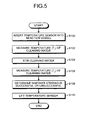
- control unit 15 rotates the cam 31 of the stirring determining device 30 to move down the arm 34 to a predetermined position and inserts the temperature sensor 36 into the reaction vessel 5 (step S100).
- control unit 15 measures a temperature (T1) of the cleaning water in the reaction vessel 5 using the temperature signal input from the temperature sensor 36 (step S102).
- the control unit 15 outputs the measured temperature (T1) of the cleaning water to the determining unit 16.
- control unit 15 drives the electric-power transmitting member 21 of the determining stirrer 28 so that the solenoid 21a causes the connecting terminal 21b to be in contact with the connecting terminal 4a for the sound-wave generating element 23 arranged on the outer surface of the reaction table 4.
- the control unit 15 drives the sound-wave generating element 23 for a certain period of time to stir the cleaning water (step S104).
- the sound-wave generating element 23 is driven, for example, for one second.
- the control unit 15 measures the temperature (T2) of the cleaning water in the reaction vessel 5 using the temperature signal input from the temperature sensor 36 (step S106). The control unit 15 outputs the measured temperature (T2) of the cleaning water to the determining unit 16. Next, the control unit 15 causes the determining unit 16 to determine whether the stirring is successful or unsuccessful (step S108). As depicted in FIG. 6 , the determining unit 16 determines whether the stirring is successful or unsuccessful on the basis of a temperature difference ( ⁇ T) between the temperature (T1) of the cleaning water before the stirring and the temperature (T2) of the cleaning water after the stirring, which have been input from the control unit 15.
- ⁇ T a temperature difference
- the control unit 15 may determine a threshold ( ⁇ Ts) concerning the temperature difference ( ⁇ T) in advance and stores the threshold ( ⁇ Ts) in the determining unit 16. If the temperature difference ( ⁇ T) is equal to or less than the threshold ( ⁇ Ts) ( ⁇ T ⁇ Ts), the control unit 15 causes the determining unit 16 to determine it as a stirring failure.
- the control unit 15 rotates the cam 31 of the stirring determining device 30 to raise the arm 34 to a predetermined position and lifts the temperature sensor 36 from the reaction vessel 5 (step S110).
- the above is the successful/unsuccessful determination of the stirring of the cleaning water using each of the reaction vessels 5, which is performed before the analysis operation is started.
- the reaction vessel 5, for which the stirring failure is determined is prevented from being used.
- the analysis of a specimen is performed by using the other reaction vessel 5, for which the stirring failure is not determined.
- the determining unit 16 may output a warning signal relating to an indication, which indicates that the stirring failure is determined, and the position number of the reaction vessel 5 to the display unit 18 via the control unit 15 so that the position of the reaction vessel 5 with the stirring failure is displayed.
- the reaction vessel 5 with the stirring failure can be removed before the specimen and the reagent are dispensed.
- the cleaning-water tank 13M is held in the constant-temperature water tank 14 in which the heater 14a is arranged.
- the cleaning water is controlled at 35 to 45°C, and the reaction table 4 is rotated while the reaction vessel 5 is kept at a predetermined temperature (for example, 37°C). Therefore, the temperature sensor 36 of the stirring determining device 30 can stably measure the temperature of the cleaning water in the reaction vessel 5 with high accuracy.
- the determination of the stirring failure of the liquid on the basis of the temperature measurement of the liquid can be performed after the analysis is finished.
- the control unit 15 displays the indication on the display unit 18 so as to alert an operator to call attention and causes an analysis to be performed again using the different reaction vessel 5 for the analysis item of the same specimen.
- the temperature of the cleaning water may be measured at certain time intervals plural times so as to set in advance a threshold (ks) concerning a gradient of a regression line of the time and the temperature of cleaning water as depicted in FIG. 7 , while driving the sound-wave generating element 23.
- a stirring failure is determined by comparing the result with the actually measured gradient (k) of the regression line. It is also possible to determine whether the stirring is successful or unsuccessful based on a threshold concerning the temperature change that is set using a curve approximation based on a hyperbolic function, an exponent function, or a logarithmic function, instead of a straight-line approximation.
- the tip end of the overflow suction nozzle 13c of the cleaning nozzle pair 13F may be lowered so as to reduce the amount of cleaning water used for the successful/unsuccessful determination of the stirring. With this, the temperature increase upon stirring at the same electric power becomes large.
- the position for stirring the liquid is the same as the position for measuring the temperature of the liquid.
- the position for stirring the liquid is different from the position for measuring the temperature of the liquid.
- FIG. 8 is a plain view that illustrates reagent dispensing systems, a specimen dispensing system, a specimen stirrer, reagent stirrers, a determining stirrer, and a stirring determining device arranged near a reaction table in an automatic analyzer according to the second embodiment.
- FIG. 9 is a schematic configuration diagram that illustrates a cleaning system used in the automatic analyzer according to the second embodiment. Because the automatic analyzers according to the second embodiment and a subsequent embodiment have the same basic configuration that includes the stirring determining device as the automatic analyzer according to the first embodiment, the same reference numerals are used for the same components.
- the determining stirrer 28 is located near the reagent stirrer 26, and the position where the determining stirrer 28 stirs the cleaning water in the reaction vessel 5 upon determining whether the stirring is successful or unsuccessful is different from the positions where the temperatures (T1, T2) of the cleaning water are measured.
- a temperature sensor T such as a thermistor or a thermocouple, is arranged near the dispensing nozzle 13b on a pipe that sends cleaning water to the dispensing nozzle 13b of the cleaning nozzle pair 13F.
- the automatic analyzer according to the second embodiment determines whether the stirring is successful or unsuccessful, independently of the analysis operation.
- the temperature (T1) of the cleaning water, which is discharged into the reaction vessel 5, is measured at the position of the cleaning system 13 before the stirring.
- the reaction table 4 moves the reaction vessel 5 that is a stirring target to the position of the cleaning nozzle pair 13F of the cleaning system 13 under the control of the control unit 15.
- the control unit 15 causes the support member 13I to move up the cleaning nozzle pair 13F together with other nozzle pairs.
- the control unit 15 rotates the reaction table 4 so as to move the reaction vessel 5 to the position of the determining stirrer 28 and causes the determining stirrer 28 to stir the cleaning water in the reaction vessel 5.
- the control unit 15 rotates the reaction table 4 so as to move the reaction vessel 5 that is a stirring target to the position of the temperature sensor 36 of the stirring determining device 30 and causes the temperature sensor 36 to measure the temperature (T2) after the stirring.
- the automatic analyzer When the position for stirring the cleaning water is different from the position for measuring the temperature, the automatic analyzer has an advantage in that the design flexibility for arranging the determining stirrer 28 and the stirring determining device 30 is increased.
- the temperature sensor is supported by the arm that moves up and down.
- the temperature sensor moves up and down with the cleaning system.
- FIG. 10 is a plain view that illustrates reagent dispensing systems, a specimen dispensing system, a specimen stirrer, reagent stirrers, a determining stirrer, and a stirring determining device arranged near a reaction table in an automatic analyzer according to the third embodiment.
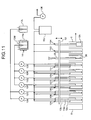
- FIG. 11 is a schematic configuration diagram that illustrates a cleaning system used in the automatic analyzer according to the third embodiment.
- the stirring determining device 30 is not provided in the automatic analyzer according to the third embodiment.
- the automatic analyzer according to the third embodiment has the support member 35 equipped with the temperature sensor 36 attached to its lower end.
- the support member 35 is arranged between the cleaning nozzle pair 13F and the suction nozzle 13G of the cleaning system 13 and supported by the support member 13I.
- the automatic analyzer measures the temperature (T1) of the cleaning water discharged into the reaction vessel 5 using the temperature sensor 36 arranged in the cleaning system 13. Then, the reaction table 4 is rotated to move the reaction vessel 5 and the cleaning water in the reaction vessel 5 is stirred by the determining stirrer 28. When the reaction table 4 is further rotated to move the reaction vessel 5 that is the stirring target to the position of the temperature sensor 36 of the cleaning system 13, the temperature (T2) of the cleaning water after the stirring is measured by the temperature sensor 36.
- the temperature sensor 36 is arranged in the cleaning system 13 instead of the stirring determining device 30. Therefore, the stirring determining device 30 that moves the temperature sensor 36 up and down does not need to be arranged in the automatic analyzer according to the third embodiment. Thus, there is an advantage in that design flexibility is increased for arranging other members or devices.
- the support rod 32 and the temperature sensor 36 are moved up and down by the cam 31 in the stirring determining device 30, but the configuration is not limited to the cam 31.
- the temperature sensor 36 can be moved up and down using a linear slide, a ball screw, or the like.
- the automatic analyzer according to the present invention can be applied to an automatic analyzer for any of a biochemical system, an immune system, and a gene system.
- a reaction vessel is a disposable type; however, in this case, it is possible that, before a specimen is dispensed into each reaction vessel and analysis is performed, the cleaning water is discharged into a reaction vessel, and, after it is confirmed that the stirring is performed successfully, the cleaning water is sucked up and removed and then the analysis is performed.
- the temperature of the cleaning water before and after the stirring which is measured each time the cleaning water contained in each reaction vessel is stirred, may be stored in the control unit 15, and the occurrence of a stirring failure may be predicted using a time-course record of the temperature of the cleaning water in each reaction vessel, or it can be used for improving the determination accuracy upon determining whether the stirring is successful or unsuccessful.
- the automatic analyzer dispenses the cleaning water, which is liquid used for the temperature measurement, by the cleaning system upon determining whether the stirring is successful or unsuccessful.
- a dispensing means that is a syringe pump may be used in order to improve the dispensing accuracy of the cleaning water.
- the above embodiment uses the wired system, in which the connecting terminal 21b of the electric-power transmitting member 21 is brought into contact with the connecting terminal 4a arranged on the outer surface of the reaction table 4 using the solenoid 21a so as to drive the sound-wave generating element 23.
- the stirring determining method according to the present invention can be used in the case where the electric-power transmitting member 21 wirelessly supplies the electric power to the sound-wave generating element 23, and it can be determined whether the stirring is successful or unsuccessful with higher accuracy than the case where a reflected signal from the sound-wave generating element 23 is detected.
- an automatic analyzer may be configured to have a plurality of analysis units.
- an automatic analyzer can include one reagent table.
- the stirring determining device, the stirring determining method, and the analyzer according to the present invention are useful for determining whether the stirring of the liquid by the sound-wave generating unit is successful or unsuccessful.
Landscapes
- Chemical & Material Sciences (AREA)
- Chemical Kinetics & Catalysis (AREA)
- Physics & Mathematics (AREA)
- General Physics & Mathematics (AREA)
- Automatic Analysis And Handling Materials Therefor (AREA)
- Accessories For Mixers (AREA)
- Investigating Or Analyzing Materials Using Thermal Means (AREA)
Abstract
Description
- The present invention relates to a stirring determining device, a stirring determining method, and an analyzer.
- A stirrer that is used in an analyzer and stirs liquid contained in a vessel without making contact using a sound-wave generating element in order to prevent what is called carry-over is conventionally known (for example, see Patent Document 1). The stirrer stirs the liquid contained in the vessel using the sound wave generated by driving the sound-wave generating element.
- Patent document 1: Japanese Patent Application Laid-open No.
2006-119125 - The stirrer disclosed in Patent Document 1 can detect the breaking of a signal line or poor connection at a terminal portion on the basis of the reflection of a drive signal supplied from a power source. However, in the stirrer disclosed in Patent Document 1, even if the sound-wave generating element is correctly operated, sometimes the generated sound wave is not propagated to the liquid contained in the vessel due to adherence failure between the sound-wave generating element and the vessel. For example, when the sound-wave generating element is separated from the vessel, or when water or an elastic material adheres to the sound-wave generating element, stirring failure may occur such that the liquid is not sufficiently stirred or cannot be stirred at all. It is difficult to determine such a stirring failure on the basis of the reflection of a drive signal. Thus, if the stirrer is used in an analyzer, it causes variation in analysis accuracy. Therefore, when used in an analyzer, it is desired for the stirrer disclosed in Patent Document 1 that it can easily and reliably determine whether the stirring of the liquid is successful or unsuccessful.
- The present invention has been made in view of the above, and an object of the present invention is to provide a stirring determining device, a stirring determining method, and an analyzer that can determine whether the stirring of the liquid using the sound-wave generating unit is successful or unsuccessful.
- To solve the problem described above and achieve the object, a stirring determining device according to the present invention determines whether stirring by a stirrer, which stirs liquid contained in a vessel using sound wave generated by a sound-wave generating unit that is attached to the vessel, is successful or unsuccessful, and includes a temperature sensor that measures a temperature of the liquid; and a determining unit that determines whether stirring of the liquid contained in the vessel is successful or unsuccessful depending on the temperature of the liquid measured at least before and after the stirring by the temperature sensor.
- To solve the problem described above and achieve the object, a stirring determining method according to the present invention for determining whether stirring by a stirrer, which stirs liquid contained in a vessel using sound wave generated by a sound-wave generating unit, is successful or unsuccessful, includes a temperature measuring step of measuring a temperature of the liquid; and a determining step of determining whether stirring of the liquid contained in the vessel is successful or unsuccessful depending on the temperature of the liquid measured at least before and after the stirring.
- In the stirring determining method according to the present invention as set forth in the invention described above, an amount of the liquid and the temperature of the liquid before the stirring are controlled within a predetermined range.
- To solve the problem described above and achieve the object, an analyzer according to the present invention that causes a stirrer to stir a plurality of different liquid contained in a vessel using sound wave generated by a sound-wave generating unit attached to the vessel to induce a reaction, and measures an optical characteristic of reaction liquid to analyze the reaction liquid, includes the stirring determining device.
- In the analyzer according to the present invention as set forth in the invention described above, a position where the temperature sensor measures the temperature of the liquid contained in the vessel is same as a position where the stirrer stirs the liquid contained in the vessel.
- In the analyzer according to the present invention as set forth in the invention described above, a position where the temperature sensor measures the temperature of the liquid contained in the vessel is different from a position where the stirrer stirs the liquid contained in the vessel.
- In the analyzer according to the present invention as set forth in the invention described above, a cleaning device that cleans the vessel is further included, and the temperature sensor is arranged in the cleaning device.
- In the analyzer according to the present invention as set forth in the invention described above, the liquid is cleaning water supplied by the cleaning device.
- In the analyzer according to the present invention as set forth in the invention described above, a control unit that controls an operation of the cleaning device such that an amount of the cleaning water supplied to the vessel upon determining whether the stirring of the liquid is successful or unsuccessful is smaller than an amount of the cleaning water supplied to the vessel upon cleaning is further included.
- In the analyzer according to the present invention as set forth in the invention described above, determination as to whether stirring of the liquid is successful or unsuccessful in accordance with temperature measurement of the liquid is performed before analysis is started or after analysis is finished.
- The stirring determining device according to the present invention includes the temperature sensor that measures the temperature of the liquid and the determining unit that determines whether the stirring of the liquid contained in the vessel is successful or unsuccessful on the basis of the temperature of the liquid measured by the temperature sensor at least before and after the stirring. The stirring determining method according to the present invention includes the temperature measuring step for measuring the temperature of the liquid and the determining step for determining whether the stirring of the liquid contained in the vessel is successful or unsuccessful on the basis of the measured temperature of the liquid at least before and after the stirring. The analyzer according to the present invention causes the stirrer to stir a plurality of different liquid contained in the vessel using sound wave generated by the sound-wave generating unit attached to the vessel to induce a reaction, and measures optical characteristics of the reaction liquid, to analyze the reaction liquid. Because the analyzer includes the stirring determining device, it produces an advantage in that it can be determined whether the stirring of the liquid using the sound-wave generating unit is successful or unsuccessful.
-
-
FIG. 1 is a schematic configuration diagram that illustrates an automatic analyzer according to a first embodiment. -
FIG. 2 is a plain view that illustrates reagent dispensing systems, a specimen dispensing system, a specimen stirrer, reagent stirrers, a determining stirrer, and a stirring determining device arranged near a reaction table in the automatic analyzer according to the first embodiment. -
FIG. 3 is a schematic configuration diagram that illustrates a cleaning system used in the automatic analyzer depicted inFIG. 1 . -
FIG. 4 is a diagram that illustrates the schematic configuration of the determining stirrer and the stirring determining device together with the cross-section surface of the reaction table that holds a reaction vessel. -
FIG. 5 is a flowchart that explains a procedure for determining whether the stirring of cleaning water using sound wave is successful or unsuccessful. -
FIG. 6 is a diagram that explains a determination method for determining whether the stirring of the liquid contained in the reaction vessel is successful or unsuccessful on the basis of the temperature of the cleaning water measured by a temperature sensor. -
FIG. 7 is a diagram that explains another determination method. -
FIG. 8 is a plain view that illustrates reagent dispensing systems, a specimen dispensing system, a specimen stirrer, reagent stirrers, a determining stirrer, and a stirring determining device arranged near the reaction table in an automatic analyzer according to a second embodiment. -
FIG. 9 is a schematic configuration diagram that illustrates a cleaning system used in the automatic analyzer according to the second embodiment. -
FIG. 10 is a plain view that illustrates reagent dispensing systems, a specimen dispensing system, a specimen stirrer, reagent stirrers, a determining stirrer, and a stirring determining device arranged near the reaction table in an automatic analyzer according to a third embodiment. -
FIG. 11 is a schematic configuration diagram that illustrates a cleaning system used in the automatic analyzer according to the third embodiment. -
- 1
- Automatic analyzer
- 2,3
- Reagent table
- 4
- Reaction table
- 5
- Reaction vessel
- 6,7
- Reagent dispensing system
- 8
- Specimen-vessel transferring system
- 9
- Feeder
- 10
- Rack
- 11
- Specimen dispensing system
- 12
- Analysis optical system
- 13
- Cleaning system
- 14
- Constant-temperature water tank
- 15
- Control unit
- 16
- Determining unit
- 17
- Input unit
- 18
- Display unit
- 20
- Specimen stirrer
- 21
- Electric-power transmitting member
- 22
- Arrangement determining member
- 23
- Sound-wave generating element
- 26,27
- Reagent stirrer
- 28
- Determining stirrer
- 30
- Stirring determining device
- 31
- Cam
- 32
- Support rod
- 33
- Guide member
- 34
- Arm
- 35
- Support member
- 36
- Temperature sensor
- T
- Thermocouple
- A detailed explanation will be given below of a first embodiment of a stirring determining device, a stirring determining method, and an analyzer according to the present invention with reference to the attached drawings.
FIG. 1 is a schematic configuration diagram that illustrates an automatic analyzer according to the first embodiment.FIG. 2 is a plain view that illustrates reagent dispensing systems, a specimen dispensing system, a specimen stirrer, reagent stirrers, a determining stirrer, and a stirring determining device arranged near a reaction table in the automatic analyzer according to the first embodiment. - As depicted in
FIGS. 1 and2 , an automatic analyzer 1 includes reagent tables 2, 3, a reaction table 4, a specimen-vessel transferring system 8, an analysisoptical system 12, acleaning system 13, acontrol unit 15, aspecimen stirrer 20,reagent stirrers stirrer 28, and astirring determining device 30. - The reagent tables 2, 3 are rotated by respective driving means so as to transfer a
reagent vessel 2a that contains a first reagent and areagent vessel 3a that contains a second reagent in a circumferential direction as depicted inFIG. 1 . - As depicted in
FIGS. 1 and2 , a plurality ofreaction vessels 5 is arranged on the reaction table 4 in a circumferential direction. The reaction table 4 is rotated while keeping the plurality ofreaction vessels 5 at a predetermined temperature, for example, 37°C, and transfers thereaction vessels 5 in a circumferential direction. A plurality of connectingterminals 4a that establishes connections with sound-wave generating elements 23 is arranged on the outer surface of the reaction table 4, where each of thereaction vessels 5 is arranged, along a circumferential direction. The reaction table 4 rotates, for example, (one revolution subtracted by one reaction vessel)/4 revolution in one cycle, and rotates (one revolution subtracted by one reaction vessel) revolution through four cycles. The plurality ofreaction vessels 5 arranged on the reaction table 4 is transferred in a circumferential direction due to the intermittent rotation of the reaction table 4. During the rotation, reagent dispensing, specimen dispensing, stirring of a liquid sample that includes a reagent and a specimen, optical measurement of a reagent, a specimen, and a reaction liquid, and cleaning are performed.Reagent dispensing systems specimen dispensing system 11, thespecimen stirrer 20, thereagent stirrers stirrer 28, and the stirring determiningdevice 30 are arranged near the reaction table 4. - The
reaction vessel 5 is a cuvette whose capacity is very small, from several µL to several hundreds of µL, and a transparent material is used, through which more than 80% of light contained in the analysis light emitted by alight emitting unit 12a of the analysisoptical system 12 is transmitted. For example, glass including heat-resistant glass or synthetic resin such as cyclic olefin and polystyrene may be used. Thereaction vessel 5 has the sound-wave generating element 23 attached to aside wall 5a (seeFIG. 4 ) and forms thestirrer 20 together with the sound-wave generating element 23. Thereaction vessel 5 is arranged on the reaction table 4 such that the sound-wave generating element 23 faces outward in a radial direction. The first reagent and the second reagent are sequentially dispensed from thereagent vessels reagent dispensing systems - The
reagent dispensing systems respective probes respective arms probes - As depicted in
FIG. 1 , the specimen-vessel transferring system 8 transfers a plurality ofracks 10 arranged on afeeder 9 step by step in the direction indicated by an arrow. Therack 10 holds a plurality ofspecimen vessels 10a that contain specimens. Each time the step transfer of therack 10 by the specimen-vessel transferring system 8 is stopped, the specimen contained in thespecimen vessel 10a is dispensed in thereaction vessel 5 by thespecimen dispensing system 11 that includes adrive arm 11a rotated in a horizontal direction and aprobe 11b. Thespecimen dispensing system 11 includes a probe cleaning means that cleans theprobe 11b using cleaning water. - The analysis
optical system 12 emits analysis light to analyze liquid contained in thereaction vessel 5 where the reagent and the specimen are reacted. As depicted inFIG. 1 , the analysis optical system includes thelight emitting unit 12a, alight splitting unit 12b, and alight receiving unit 12c. The analysis light emitted by thelight emitting unit 12a is transmitted through the liquid contained in thereaction vessel 5 and is received by thelight receiving unit 12c located at a position opposed to thelight splitting unit 12b. Thelight receiving unit 12c is connected to thecontrol unit 15 and outputs a light intensity signal of the received analysis light to thecontrol unit 15. - The
cleaning system 13 cleans thereaction vessel 5 after the optical measurement is finished. As depicted inFIG. 3 , the system includes detergent nozzle pairs 13A, 13B, cleaningnozzle pairs 13C to 13F,suction nozzles liquid tank 13J, adetergent tank 13L, a cleaning-water tank 13M, and liquid sending pumps 13N to 13S that are connected via pipes. Thecleaning system 13 sequentially cleans thereaction vessels 5 transferred due to the rotation of the reaction table 4 in the direction indicated by an arrow while moving up and down. The detergent nozzle pairs 13A, 13B, the cleaningnozzle pairs 13C to 13F, and thesuction nozzles - Each of the detergent nozzle pairs 13A, 13B and the
cleaning nozzle pairs 13C to 13F includes asuction nozzle 13a that is inserted into an area near the bottom of thereaction vessel 5, a dispensingnozzle 13b that is inserted into a middle area of thereaction vessel 5, and anoverflow suction nozzle 13c that is inserted into an upper area of thereaction vessel 5. Each nozzle has a different length. The cleaning-water tank 13M is held in a constant-temperature water tank 14 in which aheater 14a is arranged, and the cleaning water is controlled at 35 to 45°C. The inside of the waste-liquid tank 13J is maintained at a negative pressure by avacuum pump 13K. - The
detergent nozzle pair 13A sucks up the reaction liquid contained in thereaction vessel 5 using thesuction nozzle 13a, disposes of the reaction liquid into the waste-liquid tank 13J, and discharges the detergent contained in thedetergent tank 13L into thereaction vessel 5 via the dispensingnozzle 13b using theliquid sending pump 13N. At that time, theoverflow suction nozzle 13c sucks up excess detergent and disposes of the detergent into the waste-liquid tank 13J, thereby preventing the detergent from overflowing from thereaction vessel 5. Theoverflow suction nozzle 13c also prevents the overflow of the detergent or cleaning water for other nozzle pairs. - The
detergent nozzle pair 13B sucks up the detergent discharged into thereaction vessel 5 by thedetergent nozzle pair 13A using thesuction nozzle 13a, disposes of the detergent into the waste-liquid tank 13J, and discharges the detergent contained in thedetergent tank 13L into thereaction vessel 5 via the dispensingnozzle 13b using theliquid sending pump 130. - The cleaning
nozzle pair 13C sucks up the detergent discharged into thereaction vessel 5 by thedetergent nozzle pair 13B using thesuction nozzle 13a, disposes of the detergent into the waste-liquid tank 13J, and discharges the cleaning water contained in the cleaning-water tank 13M into thereaction vessel 5 via the dispensingnozzle 13b using theliquid sending pump 13P. - The cleaning
nozzle pair 13D sucks up the cleaning water discharged into thereaction vessel 5 by the cleaningnozzle pair 13C using thesuction nozzle 13a, disposes of the cleaning water into the waste-liquid tank 13J, and discharges the cleaning water contained in the cleaning-water tank 13M into thereaction vessel 5 via the dispensingnozzle 13b using theliquid sending pump 13Q. The same operation is repeatedly performed by the cleaning nozzle pairs 13E, 13F. - The cleaning
nozzle pairs 13C to 13F suck up excess detergent or cleaning water using theoverflow suction nozzle 13c so as to keep the cleaning water contained in thereaction vessel 5 at a certain amount. When thereaction vessel 5 with an inner bottom surface of 5x6 mm and a height of 30 mm is used, thereaction vessel 5 is set to contain 750 µL of cleaning water. This is set in consideration of the prevention of the overflow of the cleaning water due to the insertion of atemperature sensor 36 and a reasonable increase in the temperature of the cleaning water, which is a temperature measurement target, due to driving of the determiningstirrer 28. Thecontrol unit 15 controls the cleaningnozzle pair 13F such that, when the cleaning water is used for determining whether the stirring is successful or unsuccessful, the amount of cleaning water supplied to thereaction vessel 5 from the dispensingnozzle 13b becomes smaller than the amount of cleaning water supplied to thereaction vessel 5 from the dispensingnozzles 13b of the cleaningnozzle pairs 13C to 13E upon cleaning. - The
suction nozzle 13G sucks up the cleaning water discharged into thereaction vessel 5 by the cleaningnozzle pair 13F and disposes of the cleaning water into the waste-liquid tank 13J. Thesuction nozzle 13H has achip 13h, which is made of a synthetic resin and attached to its lower end, sucks up the cleaning water left by thesuction nozzle 13G, and disposes of the cleaning water into the waste-liquid tank 13J. - A microcomputer may be used for the
control unit 15. Thecontrol unit 15 is connected to each component of the automatic analyzer 1. Thecontrol unit 15 controls the operation of each component and analyzes constituent concentrations and the like of a specimen on the basis of the absorbance of the liquid contained in thereaction vessel 5 in accordance with the intensity of light output from thelight emitting unit 12a and the intensity of light received by thelight receiving unit 12c. Thecontrol unit 15 causes an analysis operation to be performed while controlling the operation of each component of the automatic analyzer 1 in accordance with an analysis instruction input from aninput unit 17, such as a keyboard. Thecontrol unit 15 displays on adisplay unit 18, such as a display panel, an analysis result, warning information, and various types of information in accordance with a display instruction input from theinput unit 17. - The
specimen stirrer 20, thereagent stirrers stirrer 28 perform noncontact stirring of liquid such as a specimen and a reagent contained in thereaction vessel 5 using sound wave generated by driving the sound-wave generating element 23. As depicted inFIGS. 1 and4 , the stirrer includes an electric-power transmitting member 21 and the sound-wave generating element 23. The determiningstirrer 28 is a stirrer used for easily determining whether the stirring of the liquid is successful or unsuccessful in accordance with the degree of propagation of the sound wave generated by the sound-wave generating element 23 to the cleaning water contained in thereaction vessel 5. The determining stirrer has the same configuration as thespecimen stirrer 20 and thereagent stirrers stirrer 28. Reference numerals that correspond to the corresponding components are used for thespecimen stirrer 20 and thereagent stirrers - The electric-
power transmitting member 21 is arranged such that the electric-power transmitting member 21 is opposed to thereaction vessel 5 in a horizontal direction at a position where the electric-power transmitting member 21 and the outer circumference of the reaction table 4 are opposed to each other. The electric-power transmitting member 21 sends the electric power supplied from a high-frequency alternating-current source of about several MHz to several hundreds of MHz to the sound-wave generating element 23. As depicted inFIG. 2 , the electric-power transmitting member 21 includes asolenoid 21a and a radio-frequency (RF)power source 21c as well as a driving circuit and a controller. As depicted inFIG. 4 , the electric-power transmitting member 21 causes a connecting terminal 21b to be in contact with the connecting terminal 4a for the sound-wave generating element 23 arranged on the outer surface of the reaction table 4 using thesolenoid 21a in order to drive the sound-wave generating element 23. As depicted inFIG. 1 , the electric-power transmitting member 21 is supported by anarrangement determining member 22 and, when the rotation of the reaction table 4 is stopped, sends the electric power from the connecting terminal 21b to the connecting terminal 4a so that liquid, such as a specimen and a reagent, contained in thereaction vessel 5 is stirred by the sound wave generated by the sound-wave generating element 23. - Upon sending the electric power from the electric-
power transmitting member 21 to the connecting terminal 4a, thearrangement determining member 22 moves the electric-power transmitting member 21 so as to adjust the relative arrangement of the electric-power transmitting member 21 and the connecting terminal 4a in the circumferential direction and the radial direction of the reaction table 4. - The sound-
wave generating element 23 may be configured such that a oscillator formed of a plurality of comb-teeth electrodes (IDT) is arranged on one surface of a piezoelectric substrate made of lithium niobate (LiNbO3) and is attached to theside wall 5a (seeFIG. 4 ) of thereaction vessel 5 via an acoustic matching layer such as an epoxy resin or an ultraviolet curable resin. If the sound-wave generating element 23 is driven at, for example, 1.6W for about 2.4 seconds, the temperature of the 750mL cleaning water, which is contained in thereaction vessel 5 and controlled at 35 to 45°C, is increased by about 1°C. - The stirring determining
device 30 detects the degree of propagation of the sound wave generated by the sound-wave generating element 23 to the liquid contained in thereaction vessel 5 on the basis of an increase in the temperature of the liquid in order to determine whether the stirring of the liquid is successful or unsuccessful. As depicted inFIGS. 1 ,2 , and4 , the stirring determiningdevice 30 is located at a position opposed to the determiningstirrer 28 with the reaction table 4 interposed therebetween and includes atemperature sensor 36 and a determiningunit 16. The stirring determiningdevice 30 easily and reliably determines whether the propagation of the generated sound wave to the liquid contained in thereaction vessel 5 is successful or unsuccessful. The unsuccessful propagation is sometimes caused by poor adhesion of the sound-wave generating element 23 to thereaction vessel 5, separation of the sound-wave generating element 23 from thereaction vessel 5, adherence of water or an elastic material to the surface of the sound-wave generating element 23, or the like. - The
temperature sensor 36 is provided at the lower end of asupport member 35 and measures the temperature of the liquid contained in thereaction vessel 5. For example, a thermistor or a thermocouple is used. Thesupport member 35 is supported by anarm 34 arranged on asupport rod 32 that moves up and down due to the rotation of acam 31. Thecam 31 is rotated by a driving means such as an undepicted motor. Astep portion 32a that is in contact with acam surface 31a of thecam 31 is formed in the middle of thesupport rod 32, and aguide member 33 smoothly guides the up-and-down movement of thesupport rod 32 in accordance with the rotation of thecam 31. - The determining
unit 16 is integrally formed with thecontrol unit 15 and determines whether the stirring of the liquid contained in thereaction vessel 5 is successful or unsuccessful on the basis of the change in the temperature of the liquid, which has been measured by thetemperature sensor 36, before and after the stirring. - The automatic analyzer 1 that has the configuration as described above is operated under the control of the
control unit 15 so that the first reagent, the second reagent, and the specimen are sequentially dispensed by thereagent dispensing systems specimen dispensing system 11 in the plurality ofreaction vessels 5 transferred by the rotating reaction table 4 in a circumferential direction. The dispensed reagents and specimen are sequentially stirred by thereagent stirrers specimen stirrer 20. - When the
reaction vessel 5, in which the reagents and the specimen have been stirred, passes by the analysisoptical system 12, the optical characteristics of the reaction liquid are measured by thelight receiving unit 12c, and the constituent concentration or the like is analyzed by thecontrol unit 15. Thereaction vessel 5, for which the optical measurement of the reaction liquid is finished, is cleaned by thecleaning system 13 and then is used for analysis of a specimen again. - Before the analysis is started or after the analysis is finished, the automatic analyzer 1 determines, independently of the analysis operation, whether the stirring of the cleaning water is successful or unsuccessful using the sound wave generated by the sound-
wave generating element 23. For example, the automatic analyzer 1 usually cleansreaction vessels 5 using thecleaning system 13 before the analysis is started, and, at that time, the automatic analyzer 1 detects the degree of propagation of the sound wave generated by the sound-wave generating element 23 to the cleaning water contained in thereaction vessel 5 on the basis of an increase in the temperature of the cleaning water. Thus, whether the stirring of the cleaning water due to the sound wave generated by the sound-wave generating element 23 is successful or unsuccessful can be easily and reliably determined using thestirring determining device 30. - In that case, the
control unit 15 causes the dispensingnozzle 13b of the cleaningnozzle pair 13F to discharge a certain amount of cleaning water into eachreaction vessel 5 transferred to the position of thecleaning system 13 by rotating the reaction table 4 and then causes the support member 13I to raise thecleaning nozzle pair 13F together with the other nozzle pairs. Then, each of thereaction vessels 5 is sequentially transferred to the position of the determiningstirrer 28 by rotating the reaction table 4, and it is determined whether the stirring of the cleaning water using sound wave is successful or unsuccessful. The cleaning water in thereaction vessel 5 after the measurement of a temperature (T2) is sucked up by thecleaning system 13. An explanation will be given below of the procedure for the successful/unsuccessful determination performed by thecontrol unit 15 with reference to the flowchart depicted inFIG. 5 . - First, the
control unit 15 rotates thecam 31 of the stirring determiningdevice 30 to move down thearm 34 to a predetermined position and inserts thetemperature sensor 36 into the reaction vessel 5 (step S100). Next, thecontrol unit 15 measures a temperature (T1) of the cleaning water in thereaction vessel 5 using the temperature signal input from the temperature sensor 36 (step S102). Thecontrol unit 15 outputs the measured temperature (T1) of the cleaning water to the determiningunit 16. - Next, the
control unit 15 drives the electric-power transmitting member 21 of the determiningstirrer 28 so that thesolenoid 21a causes the connecting terminal 21b to be in contact with the connecting terminal 4a for the sound-wave generating element 23 arranged on the outer surface of the reaction table 4. Thus, thecontrol unit 15 drives the sound-wave generating element 23 for a certain period of time to stir the cleaning water (step S104). The sound-wave generating element 23 is driven, for example, for one second. - After the cleaning water is stirred for a certain period of time, the
control unit 15 measures the temperature (T2) of the cleaning water in thereaction vessel 5 using the temperature signal input from the temperature sensor 36 (step S106). Thecontrol unit 15 outputs the measured temperature (T2) of the cleaning water to the determiningunit 16. Next, thecontrol unit 15 causes the determiningunit 16 to determine whether the stirring is successful or unsuccessful (step S108). As depicted inFIG. 6 , the determiningunit 16 determines whether the stirring is successful or unsuccessful on the basis of a temperature difference (ΔT) between the temperature (T1) of the cleaning water before the stirring and the temperature (T2) of the cleaning water after the stirring, which have been input from thecontrol unit 15. - Even if the sound-
wave generating element 23 of the determiningstirrer 28 is correctly operated, the generated sound wave is not propagated to the cleaning water contained in thereaction vessel 5 and the cleaning water is not stirred when, for example, the sound-wave generating element 23 is separated from the reaction vessel. Thus, the temperature of the cleaning water is not increased although the sound-wave generating element 23 is operated. Thecontrol unit 15 may determine a threshold (ΔTs) concerning the temperature difference (ΔT) in advance and stores the threshold (ΔTs) in the determiningunit 16. If the temperature difference (ΔT) is equal to or less than the threshold (ΔTs) (ΔT≤ΔTs), thecontrol unit 15 causes the determiningunit 16 to determine it as a stirring failure. - Next, the
control unit 15 rotates thecam 31 of the stirring determiningdevice 30 to raise thearm 34 to a predetermined position and lifts thetemperature sensor 36 from the reaction vessel 5 (step S110). The above is the successful/unsuccessful determination of the stirring of the cleaning water using each of thereaction vessels 5, which is performed before the analysis operation is started. Thereaction vessel 5, for which the stirring failure is determined, is prevented from being used. The analysis of a specimen is performed by using theother reaction vessel 5, for which the stirring failure is not determined. At that time, the determiningunit 16 may output a warning signal relating to an indication, which indicates that the stirring failure is determined, and the position number of thereaction vessel 5 to thedisplay unit 18 via thecontrol unit 15 so that the position of thereaction vessel 5 with the stirring failure is displayed. - As described, if it is determined whether the stirring is successful or unsuccessful before the analysis is started, the
reaction vessel 5 with the stirring failure can be removed before the specimen and the reagent are dispensed. Thus, it is possible to prevent the waste of the specimen and the reagent and prevent the output of an incorrect analysis value due to the stirring failure. In thecleaning system 13, the cleaning-water tank 13M is held in the constant-temperature water tank 14 in which theheater 14a is arranged. The cleaning water is controlled at 35 to 45°C, and the reaction table 4 is rotated while thereaction vessel 5 is kept at a predetermined temperature (for example, 37°C). Therefore, thetemperature sensor 36 of the stirring determiningdevice 30 can stably measure the temperature of the cleaning water in thereaction vessel 5 with high accuracy. - The determination of the stirring failure of the liquid on the basis of the temperature measurement of the liquid can be performed after the analysis is finished. In this case, because an analysis result using the
reaction vessel 5 for which the stirring failure is determined is not reliable, thecontrol unit 15 displays the indication on thedisplay unit 18 so as to alert an operator to call attention and causes an analysis to be performed again using thedifferent reaction vessel 5 for the analysis item of the same specimen. - When determining whether the stirring is successful or unsuccessful, the temperature of the cleaning water may be measured at certain time intervals plural times so as to set in advance a threshold (ks) concerning a gradient of a regression line of the time and the temperature of cleaning water as depicted in
FIG. 7 , while driving the sound-wave generating element 23. A stirring failure is determined by comparing the result with the actually measured gradient (k) of the regression line. It is also possible to determine whether the stirring is successful or unsuccessful based on a threshold concerning the temperature change that is set using a curve approximation based on a hyperbolic function, an exponent function, or a logarithmic function, instead of a straight-line approximation. - Furthermore, the tip end of the
overflow suction nozzle 13c of the cleaningnozzle pair 13F may be lowered so as to reduce the amount of cleaning water used for the successful/unsuccessful determination of the stirring. With this, the temperature increase upon stirring at the same electric power becomes large. - Next, a detailed explanation will be given of a second embodiment of the stirring determining device, the stirring determining method, and the analyzer according to the present invention with reference to the attached drawings. In the first embodiment, the position for stirring the liquid is the same as the position for measuring the temperature of the liquid. In the second embodiment, the position for stirring the liquid is different from the position for measuring the temperature of the liquid.
-
FIG. 8 is a plain view that illustrates reagent dispensing systems, a specimen dispensing system, a specimen stirrer, reagent stirrers, a determining stirrer, and a stirring determining device arranged near a reaction table in an automatic analyzer according to the second embodiment.FIG. 9 is a schematic configuration diagram that illustrates a cleaning system used in the automatic analyzer according to the second embodiment. Because the automatic analyzers according to the second embodiment and a subsequent embodiment have the same basic configuration that includes the stirring determining device as the automatic analyzer according to the first embodiment, the same reference numerals are used for the same components. - In the automatic analyzer according to the second embodiment, as depicted in
FIG. 8 , the determiningstirrer 28 is located near thereagent stirrer 26, and the position where the determiningstirrer 28 stirs the cleaning water in thereaction vessel 5 upon determining whether the stirring is successful or unsuccessful is different from the positions where the temperatures (T1, T2) of the cleaning water are measured. Specifically, as depicted inFIG. 9 , in thecleaning system 13 used in the automatic analyzer according to the second embodiment, a temperature sensor T, such as a thermistor or a thermocouple, is arranged near the dispensingnozzle 13b on a pipe that sends cleaning water to the dispensingnozzle 13b of the cleaningnozzle pair 13F. In the same manner as the automatic analyzer according to the first embodiment, before the analysis is started or after the analysis is finished, the automatic analyzer according to the second embodiment determines whether the stirring is successful or unsuccessful, independently of the analysis operation. The temperature (T1) of the cleaning water, which is discharged into thereaction vessel 5, is measured at the position of thecleaning system 13 before the stirring. - In the second embodiment, the reaction table 4 moves the
reaction vessel 5 that is a stirring target to the position of the cleaningnozzle pair 13F of thecleaning system 13 under the control of thecontrol unit 15. Next, after thecontrol unit 15 causes a certain amount of cleaning water to be discharged into thereaction vessel 5 from the dispensingnozzle 13b, thecontrol unit 15 causes the support member 13I to move up the cleaningnozzle pair 13F together with other nozzle pairs. Then, thecontrol unit 15 rotates the reaction table 4 so as to move thereaction vessel 5 to the position of the determiningstirrer 28 and causes the determiningstirrer 28 to stir the cleaning water in thereaction vessel 5. - After the stirring, the
control unit 15 rotates the reaction table 4 so as to move thereaction vessel 5 that is a stirring target to the position of thetemperature sensor 36 of the stirring determiningdevice 30 and causes thetemperature sensor 36 to measure the temperature (T2) after the stirring. The determiningunit 16 then determines whether the stirring is successful or unsuccessful on the basis of the temperature difference (ΔT=T2-T1) between the temperature (T1) of the cleaning water before the stirring and the temperature (T2) of the cleaning water after the stirring, which is measured by thetemperature sensor 36, by comparing the temperature difference with the certain threshold ΔTs set in advance. After the temperature (T2) is measured, the cleaning water in thereaction vessel 5 is sucked up by thecleaning system 13. - Even if the same stirring energy is applied to the cleaning water by the determining
stirrer 28 upon the stirring, the increased temperature is different depending on the temperature (T1) before the stirring, and the temperature difference (ΔT=T2-T1) can be different. Therefore, for example, as indicated in Table 1, the threshold ΔTs is set in advance concerning the temperature difference (ΔT=T2-T1) for each range of the temperature (T1) before the stirring and is stored in the determiningunit 16. If the temperature difference (ΔT) is equal to or less than the threshold ΔTs (ΔT≤ΔTs), the determiningunit 16 determines it as a stirring failure. In this manner, the automatic analyzer according to the second embodiment can further improve the accuracy of the successful/unsuccessful determination of the stirring performed by the determiningunit 16 compared to the automatic analyzer according to the first embodiment. -
Table 1 Condition ΔTs Remarks T1<35 - Determine as cleaning-water temperature control error 35≤T1<36 0.9 36≤T1<37 0.89 37≤T1<38 0.86 38≤T1<39 0.83 39≤T1<40 0.8 40≤T1<41 0.77 41≤T1<42 0.73 42≤T1<43 0.69 43≤T1<44 0.64 44≤T1<45 0.6 45<T1 - Determine as cleaning-water temperature control error - When the position for stirring the cleaning water is different from the position for measuring the temperature, the automatic analyzer has an advantage in that the design flexibility for arranging the determining
stirrer 28 and the stirring determiningdevice 30 is increased. - The determining
unit 16 may determine whether the stirring is successful or unsuccessful by comparing the temperature difference (ΔT=T2-T1) with the single threshold ΔTs in the same manner as the first embodiment. - Next, a detailed explanation will be given of a third embodiment of the stirring determining device, the stirring determining method, and the analyzer according to the present invention with reference to the attached drawings. In the first embodiment, the temperature sensor is supported by the arm that moves up and down. In the third embodiment, the temperature sensor moves up and down with the cleaning system.
-
FIG. 10 is a plain view that illustrates reagent dispensing systems, a specimen dispensing system, a specimen stirrer, reagent stirrers, a determining stirrer, and a stirring determining device arranged near a reaction table in an automatic analyzer according to the third embodiment.FIG. 11 is a schematic configuration diagram that illustrates a cleaning system used in the automatic analyzer according to the third embodiment. - As depicted in
FIG. 10 , the stirring determiningdevice 30 is not provided in the automatic analyzer according to the third embodiment. In place of the stirring determiningdevice 30, as depicted inFIG. 11 , the automatic analyzer according to the third embodiment has thesupport member 35 equipped with thetemperature sensor 36 attached to its lower end. Thesupport member 35 is arranged between the cleaningnozzle pair 13F and thesuction nozzle 13G of thecleaning system 13 and supported by the support member 13I. - The automatic analyzer according to the third embodiment measures the temperature (T1) of the cleaning water discharged into the
reaction vessel 5 using thetemperature sensor 36 arranged in thecleaning system 13. Then, the reaction table 4 is rotated to move thereaction vessel 5 and the cleaning water in thereaction vessel 5 is stirred by the determiningstirrer 28. When the reaction table 4 is further rotated to move thereaction vessel 5 that is the stirring target to the position of thetemperature sensor 36 of thecleaning system 13, the temperature (T2) of the cleaning water after the stirring is measured by thetemperature sensor 36. The determiningunit 16 then compares the temperature difference (ΔT=T2-T1) between the temperature (T1) of the cleaning water before the stirring and the temperature (T2) of the cleaning water after the stirring with the certain threshold ΔTs set in advance in order to determine whether the stirring is successful or unsuccessful. - In the automatic analyzer according to the third embodiment, the
temperature sensor 36 is arranged in thecleaning system 13 instead of the stirring determiningdevice 30. Therefore, the stirring determiningdevice 30 that moves thetemperature sensor 36 up and down does not need to be arranged in the automatic analyzer according to the third embodiment. Thus, there is an advantage in that design flexibility is increased for arranging other members or devices. - In the first and second embodiments, the
support rod 32 and thetemperature sensor 36 are moved up and down by thecam 31 in the stirring determiningdevice 30, but the configuration is not limited to thecam 31. For example, thetemperature sensor 36 can be moved up and down using a linear slide, a ball screw, or the like. - The automatic analyzer according to the present invention can be applied to an automatic analyzer for any of a biochemical system, an immune system, and a gene system. In an automatic analyzer for a gene system, a reaction vessel is a disposable type; however, in this case, it is possible that, before a specimen is dispensed into each reaction vessel and analysis is performed, the cleaning water is discharged into a reaction vessel, and, after it is confirmed that the stirring is performed successfully, the cleaning water is sucked up and removed and then the analysis is performed.
- In the present invention, the temperature of the cleaning water before and after the stirring, which is measured each time the cleaning water contained in each reaction vessel is stirred, may be stored in the
control unit 15, and the occurrence of a stirring failure may be predicted using a time-course record of the temperature of the cleaning water in each reaction vessel, or it can be used for improving the determination accuracy upon determining whether the stirring is successful or unsuccessful. - The automatic analyzer according to the present invention dispenses the cleaning water, which is liquid used for the temperature measurement, by the cleaning system upon determining whether the stirring is successful or unsuccessful. A dispensing means that is a syringe pump may be used in order to improve the dispensing accuracy of the cleaning water.
- Furthermore, the above embodiment uses the wired system, in which the connecting terminal 21b of the electric-
power transmitting member 21 is brought into contact with the connecting terminal 4a arranged on the outer surface of the reaction table 4 using thesolenoid 21a so as to drive the sound-wave generating element 23. However, the stirring determining method according to the present invention can be used in the case where the electric-power transmitting member 21 wirelessly supplies the electric power to the sound-wave generating element 23, and it can be determined whether the stirring is successful or unsuccessful with higher accuracy than the case where a reflected signal from the sound-wave generating element 23 is detected. - Although the case is explained where the automatic analyzer described in the embodiments includes one reaction table 4, i.e., one analysis unit, an automatic analyzer may be configured to have a plurality of analysis units. Although the case is explained where the two reagent tables for the first reagent and the second reagent are arranged, an automatic analyzer can include one reagent table.
- As described above, the stirring determining device, the stirring determining method, and the analyzer according to the present invention are useful for determining whether the stirring of the liquid by the sound-wave generating unit is successful or unsuccessful.
Claims (10)
- A stirring determining device that determines whether stirring by a stirrer, which stirs liquid contained in a vessel using sound wave generated by a sound-wave generating unit that is attached to the vessel, is successful or unsuccessful, the stirring determining device comprising:a temperature sensor that measures a temperature of the liquid; anda determining unit that determines whether stirring of the liquid contained in the vessel is successful or unsuccessful depending on the temperature of the liquid measured at least before and after the stirring by the temperature sensor.
- A stirring determining method for determining whether stirring by a stirrer, which stirs liquid contained in a vessel using sound wave generated by a sound-wave generating unit, is successful or unsuccessful, the stirring determining method comprising:a temperature measuring step of measuring a temperature of the liquid; anda determining step of determining whether stirring of the liquid contained in the vessel is successful or unsuccessful depending on the temperature of the liquid measured at least before and after the stirring.
- The stirring determining method according to claim 2, wherein an amount of the liquid and the temperature of the liquid before the stirring are controlled within a predetermined range.
- An analyzer that causes a stirrer to stir a plurality of different liquid contained in a vessel using sound wave generated by a sound-wave generating unit attached to the vessel to induce a reaction, and measures an optical characteristic of reaction liquid to analyze the reaction liquid, the analyzer comprising the stirring determining device according to claim 1.
- The analyzer according to claim 4, wherein a position where the temperature sensor measures the temperature of the liquid contained in the vessel is same as a position where the stirrer stirs the liquid contained in the vessel.
- The analyzer according to claim 4, wherein a position where the temperature sensor measures the temperature of the liquid contained in the vessel is different from a position where the stirrer stirs the liquid contained in the vessel.
- The analyzer according to claim 6, further comprising a cleaning device that cleans the vessel, wherein
the temperature sensor is arranged in the cleaning device. - The analyzer according to claim 7, wherein the liquid is cleaning water supplied by the cleaning device.
- The analyzer according to claim 8, further comprising a control unit that controls an operation of the cleaning device such that an amount of the cleaning water supplied to the vessel upon determining whether the stirring of the liquid is successful or unsuccessful is smaller than an amount of the cleaning water supplied to the vessel upon cleaning.
- The analyzer according to claim 4, wherein determination as to whether stirring of the liquid is successful or unsuccessful in accordance with temperature measurement of the liquid is performed before analysis is started or after analysis is finished.
Applications Claiming Priority (2)
| Application Number | Priority Date | Filing Date | Title |
|---|---|---|---|
| JP2007187052 | 2007-07-18 | ||
| PCT/JP2008/062605 WO2009011313A1 (en) | 2007-07-18 | 2008-07-11 | Stirring determination device, stirring determination method, and analyzer |
Publications (3)
| Publication Number | Publication Date |
|---|---|
| EP2180324A1 true EP2180324A1 (en) | 2010-04-28 |
| EP2180324A4 EP2180324A4 (en) | 2012-08-15 |
| EP2180324B1 EP2180324B1 (en) | 2013-11-20 |
Family
ID=40259646
Family Applications (1)
| Application Number | Title | Priority Date | Filing Date |
|---|---|---|---|
| EP08791086.5A Not-in-force EP2180324B1 (en) | 2007-07-18 | 2008-07-11 | Analyzer comprising a stirring determination device and stirring determination method |
Country Status (5)
| Country | Link |
|---|---|
| US (1) | US8197126B2 (en) |
| EP (1) | EP2180324B1 (en) |
| JP (1) | JP5222848B2 (en) |
| CN (1) | CN101755212B (en) |
| WO (1) | WO2009011313A1 (en) |
Families Citing this family (9)
| Publication number | Priority date | Publication date | Assignee | Title |
|---|---|---|---|---|
| ES2587590T3 (en) * | 2007-07-18 | 2016-10-25 | Beckman Coulter, Inc. | Analysis apparatus and its anomaly elimination method |
| JP5219461B2 (en) * | 2007-11-02 | 2013-06-26 | ベックマン コールター, インコーポレイテッド | Agitation judgment method and analyzer |
| JP2013068418A (en) * | 2011-09-20 | 2013-04-18 | Kawata Mfg Co Ltd | Processing unit |
| US20140190357A1 (en) * | 2013-01-09 | 2014-07-10 | Ka Chun MAK | Bottle Temperature Control Apparatus |
| JP6751008B2 (en) * | 2016-11-21 | 2020-09-02 | 日本スピンドル製造株式会社 | Kneading state determination system, kneading state determination device, operation screen of kneading state determination system, and kneading state determination auxiliary system |
| TWI766942B (en) | 2017-02-13 | 2022-06-11 | 美商海科生醫有限責任公司 | Apparatuses and methods for mixing fluid or media by vibrating a pipette using transient and steady-state intervals |
| CN110508189B (en) * | 2019-08-12 | 2021-10-01 | 深圳中研塑力科技有限公司 | Solution stirring detects with self-cleaning formula sensor |
| EP4252008A4 (en) * | 2020-11-30 | 2024-10-23 | Beckman Coulter, Inc. | Mixing heater setpoint change |
| WO2023145353A1 (en) * | 2022-01-31 | 2023-08-03 | 株式会社日立ハイテク | Automated analyzing device |
Family Cites Families (19)
| Publication number | Priority date | Publication date | Assignee | Title |
|---|---|---|---|---|
| US2828231A (en) * | 1954-03-31 | 1958-03-25 | Gen Electric | Method and apparatus for ultrasonic cleansing |
| US3457108A (en) * | 1964-08-03 | 1969-07-22 | Dow Chemical Co | Method of removing adherent materials |
| US3507695A (en) * | 1967-04-18 | 1970-04-21 | Beehler Vernon D | Utilization of sound wave energy |
| JPS61274651A (en) * | 1985-05-29 | 1986-12-04 | Nissei Reiki Kk | Method for cleaning soft cream manufacturing machine and apparatus therefor |
| JPH0723559B2 (en) * | 1989-06-12 | 1995-03-15 | ダイセル化学工業株式会社 | Stamper cleaning device |
| DE69102311T2 (en) * | 1990-03-07 | 1994-09-29 | Hitachi Ltd | Device and method for surface cleaning. |
| DE69521035T2 (en) * | 1994-03-18 | 2001-10-18 | Kao Corp., Tokio/Tokyo | CLEANING PROCEDURE |
| JPH08211592A (en) * | 1995-02-07 | 1996-08-20 | Nikon Corp | Cleaning / drying method and cleaning / drying apparatus |
| US6787112B1 (en) * | 1998-08-13 | 2004-09-07 | Symyx Technologies, Inc. | Parallel reactor with internal sensing and method of using same |
| US6528026B2 (en) * | 1998-08-13 | 2003-03-04 | Symyx Technologies, Inc. | Multi-temperature modular reactor and method of using same |
| US6719449B1 (en) * | 1998-10-28 | 2004-04-13 | Covaris, Inc. | Apparatus and method for controlling sonic treatment |
| JP2001188070A (en) * | 1999-12-28 | 2001-07-10 | Hitachi Ltd | Automatic analyzer and automatic analysis method |
| WO2001063300A1 (en) * | 2000-02-23 | 2001-08-30 | Hitachi, Ltd. | Automatic analyzer |
| DE10060891C1 (en) * | 2000-12-07 | 2002-07-25 | Wack O K Chemie Gmbh | Process for liquid cleaning objects |
| JP4365813B2 (en) | 2004-09-22 | 2009-11-18 | オリンパス株式会社 | Stirring device, container and analyzer equipped with stirrer |
| US7520287B2 (en) * | 2005-01-28 | 2009-04-21 | Kozy David M | Aqueous tube cleaning apparatus and method |
| US7543354B2 (en) * | 2005-11-04 | 2009-06-09 | Logan Instruments Corporation | Brush head for automatic dissolution vessel cleaner |
| EP1995597A1 (en) * | 2006-03-15 | 2008-11-26 | Olympus Corporation | Stirring device and analyzer |
| CN101905985B (en) * | 2010-07-30 | 2012-11-28 | 河北省微生物研究所 | Method for preparing microorganism-decomposing agent used for producing biological organic fertilizer by livestock and poultry manure fermentation |
-
2008
- 2008-07-11 CN CN2008800252043A patent/CN101755212B/en not_active Expired - Fee Related
- 2008-07-11 WO PCT/JP2008/062605 patent/WO2009011313A1/en not_active Ceased
- 2008-07-11 JP JP2009523636A patent/JP5222848B2/en not_active Expired - Fee Related
- 2008-07-11 EP EP08791086.5A patent/EP2180324B1/en not_active Not-in-force
-
2010
- 2010-01-14 US US12/687,644 patent/US8197126B2/en not_active Expired - Fee Related
Also Published As
| Publication number | Publication date |
|---|---|
| JP5222848B2 (en) | 2013-06-26 |
| JPWO2009011313A1 (en) | 2010-09-24 |
| CN101755212B (en) | 2013-11-06 |
| EP2180324B1 (en) | 2013-11-20 |
| EP2180324A4 (en) | 2012-08-15 |
| CN101755212A (en) | 2010-06-23 |
| US8197126B2 (en) | 2012-06-12 |
| US20100135352A1 (en) | 2010-06-03 |
| WO2009011313A1 (en) | 2009-01-22 |
Similar Documents
| Publication | Publication Date | Title |
|---|---|---|
| EP2180324B1 (en) | Analyzer comprising a stirring determination device and stirring determination method | |
| CN101755213B (en) | Analyzing device and method for handling abnormality thereof | |
| JP5140497B2 (en) | Analysis apparatus and analysis method | |
| EP2182369A1 (en) | Automatic analyzing device and dispensing method | |
| US8911685B2 (en) | Automated analyzer | |
| JP6581905B2 (en) | Automatic analyzer | |
| US11879904B2 (en) | Method of washing an aspiration probe of an in-vitro diagnostic system, in-vitro diagnostic method, and in-vitro diagnostic system | |
| EP2023145A1 (en) | Automatic analyzer and method of determining dispensing failure | |
| JP5236612B2 (en) | Automatic analyzer | |
| WO2017163613A1 (en) | Automated analyzer | |
| JP2011128075A (en) | Automatic analyzer, and specimen stirring method and specimen dispensation method of the automatic analyzer | |
| JP5583337B2 (en) | Automatic analyzer and its dispensing method | |
| JP2009031203A (en) | Automatic analyzer | |
| CN110352355B (en) | Automatic analysis device and analysis method | |
| WO2009148013A1 (en) | Method for cleaning probe in analyte dispensing device, analyte dispensing device and automatic analyzer | |
| JP2008256566A (en) | Dispenser and autoanalyzer | |
| JP2008003057A (en) | Analyzer and analysis method | |
| JP7309467B2 (en) | automatic analyzer | |
| JPS63195572A (en) | Dispensing device | |
| CN117288967A (en) | Sample analyzer and cleaning flow detection method | |
| CN121454078A (en) | Sample analyzer and cleaning components | |
| JP2009053113A (en) | Cleaning device and automatic analyzer |
Legal Events
| Date | Code | Title | Description |
|---|---|---|---|
| PUAI | Public reference made under article 153(3) epc to a published international application that has entered the european phase |
Free format text: ORIGINAL CODE: 0009012 |
|
| 17P | Request for examination filed |
Effective date: 20100218 |
|
| AK | Designated contracting states |
Kind code of ref document: A1 Designated state(s): AT BE BG CH CY CZ DE DK EE ES FI FR GB GR HR HU IE IS IT LI LT LU LV MC MT NL NO PL PT RO SE SI SK TR |
|
| AX | Request for extension of the european patent |
Extension state: AL BA MK RS |
|
| RAP1 | Party data changed (applicant data changed or rights of an application transferred) |
Owner name: BECKMAN COULTER, INC. |
|
| DAX | Request for extension of the european patent (deleted) | ||
| A4 | Supplementary search report drawn up and despatched |
Effective date: 20120716 |
|
| RIC1 | Information provided on ipc code assigned before grant |
Ipc: G01N 35/02 20060101AFI20120710BHEP Ipc: B01F 11/02 20060101ALI20120710BHEP Ipc: B01F 15/00 20060101ALI20120710BHEP |
|
| GRAP | Despatch of communication of intention to grant a patent |
Free format text: ORIGINAL CODE: EPIDOSNIGR1 |
|
| RIC1 | Information provided on ipc code assigned before grant |
Ipc: G01K 1/14 20060101ALI20130530BHEP Ipc: B01F 15/00 20060101ALI20130530BHEP Ipc: B01F 11/02 20060101ALI20130530BHEP Ipc: G01N 35/02 20060101AFI20130530BHEP |
|
| INTG | Intention to grant announced |
Effective date: 20130619 |
|
| GRAS | Grant fee paid |
Free format text: ORIGINAL CODE: EPIDOSNIGR3 |
|
| GRAA | (expected) grant |
Free format text: ORIGINAL CODE: 0009210 |
|
| AK | Designated contracting states |
Kind code of ref document: B1 Designated state(s): AT BE BG CH CY CZ DE DK EE ES FI FR GB GR HR HU IE IS IT LI LT LU LV MC MT NL NO PL PT RO SE SI SK TR |
|
| REG | Reference to a national code |
Ref country code: GB Ref legal event code: FG4D |
|
| REG | Reference to a national code |
Ref country code: CH Ref legal event code: EP |
|
| REG | Reference to a national code |
Ref country code: AT Ref legal event code: REF Ref document number: 641940 Country of ref document: AT Kind code of ref document: T Effective date: 20131215 |
|
| REG | Reference to a national code |
Ref country code: IE Ref legal event code: FG4D |
|
| REG | Reference to a national code |
Ref country code: DE Ref legal event code: R096 Ref document number: 602008028863 Country of ref document: DE Effective date: 20140116 |
|
| REG | Reference to a national code |
Ref country code: NL Ref legal event code: VDEP Effective date: 20131120 |
|
| REG | Reference to a national code |
Ref country code: AT Ref legal event code: MK05 Ref document number: 641940 Country of ref document: AT Kind code of ref document: T Effective date: 20131120 |
|
| REG | Reference to a national code |
Ref country code: LT Ref legal event code: MG4D |
|
| PG25 | Lapsed in a contracting state [announced via postgrant information from national office to epo] |
Ref country code: IS Free format text: LAPSE BECAUSE OF FAILURE TO SUBMIT A TRANSLATION OF THE DESCRIPTION OR TO PAY THE FEE WITHIN THE PRESCRIBED TIME-LIMIT Effective date: 20140320 Ref country code: FI Free format text: LAPSE BECAUSE OF FAILURE TO SUBMIT A TRANSLATION OF THE DESCRIPTION OR TO PAY THE FEE WITHIN THE PRESCRIBED TIME-LIMIT Effective date: 20131120 Ref country code: NL Free format text: LAPSE BECAUSE OF FAILURE TO SUBMIT A TRANSLATION OF THE DESCRIPTION OR TO PAY THE FEE WITHIN THE PRESCRIBED TIME-LIMIT Effective date: 20131120 Ref country code: LT Free format text: LAPSE BECAUSE OF FAILURE TO SUBMIT A TRANSLATION OF THE DESCRIPTION OR TO PAY THE FEE WITHIN THE PRESCRIBED TIME-LIMIT Effective date: 20131120 Ref country code: HR Free format text: LAPSE BECAUSE OF FAILURE TO SUBMIT A TRANSLATION OF THE DESCRIPTION OR TO PAY THE FEE WITHIN THE PRESCRIBED TIME-LIMIT Effective date: 20131120 Ref country code: SE Free format text: LAPSE BECAUSE OF FAILURE TO SUBMIT A TRANSLATION OF THE DESCRIPTION OR TO PAY THE FEE WITHIN THE PRESCRIBED TIME-LIMIT Effective date: 20131120 Ref country code: NO Free format text: LAPSE BECAUSE OF FAILURE TO SUBMIT A TRANSLATION OF THE DESCRIPTION OR TO PAY THE FEE WITHIN THE PRESCRIBED TIME-LIMIT Effective date: 20140220 |
|
| PG25 | Lapsed in a contracting state [announced via postgrant information from national office to epo] |
Ref country code: ES Free format text: LAPSE BECAUSE OF FAILURE TO SUBMIT A TRANSLATION OF THE DESCRIPTION OR TO PAY THE FEE WITHIN THE PRESCRIBED TIME-LIMIT Effective date: 20131120 Ref country code: AT Free format text: LAPSE BECAUSE OF FAILURE TO SUBMIT A TRANSLATION OF THE DESCRIPTION OR TO PAY THE FEE WITHIN THE PRESCRIBED TIME-LIMIT Effective date: 20131120 Ref country code: LV Free format text: LAPSE BECAUSE OF FAILURE TO SUBMIT A TRANSLATION OF THE DESCRIPTION OR TO PAY THE FEE WITHIN THE PRESCRIBED TIME-LIMIT Effective date: 20131120 Ref country code: BE Free format text: LAPSE BECAUSE OF FAILURE TO SUBMIT A TRANSLATION OF THE DESCRIPTION OR TO PAY THE FEE WITHIN THE PRESCRIBED TIME-LIMIT Effective date: 20131120 |
|
| PG25 | Lapsed in a contracting state [announced via postgrant information from national office to epo] |
Ref country code: PT Free format text: LAPSE BECAUSE OF FAILURE TO SUBMIT A TRANSLATION OF THE DESCRIPTION OR TO PAY THE FEE WITHIN THE PRESCRIBED TIME-LIMIT Effective date: 20140320 |
|
| PG25 | Lapsed in a contracting state [announced via postgrant information from national office to epo] |
Ref country code: EE Free format text: LAPSE BECAUSE OF FAILURE TO SUBMIT A TRANSLATION OF THE DESCRIPTION OR TO PAY THE FEE WITHIN THE PRESCRIBED TIME-LIMIT Effective date: 20131120 |
|
| REG | Reference to a national code |
Ref country code: DE Ref legal event code: R097 Ref document number: 602008028863 Country of ref document: DE |
|
| PG25 | Lapsed in a contracting state [announced via postgrant information from national office to epo] |
Ref country code: CZ Free format text: LAPSE BECAUSE OF FAILURE TO SUBMIT A TRANSLATION OF THE DESCRIPTION OR TO PAY THE FEE WITHIN THE PRESCRIBED TIME-LIMIT Effective date: 20131120 Ref country code: RO Free format text: LAPSE BECAUSE OF FAILURE TO SUBMIT A TRANSLATION OF THE DESCRIPTION OR TO PAY THE FEE WITHIN THE PRESCRIBED TIME-LIMIT Effective date: 20131120 Ref country code: SK Free format text: LAPSE BECAUSE OF FAILURE TO SUBMIT A TRANSLATION OF THE DESCRIPTION OR TO PAY THE FEE WITHIN THE PRESCRIBED TIME-LIMIT Effective date: 20131120 Ref country code: PL Free format text: LAPSE BECAUSE OF FAILURE TO SUBMIT A TRANSLATION OF THE DESCRIPTION OR TO PAY THE FEE WITHIN THE PRESCRIBED TIME-LIMIT Effective date: 20131120 |
|
| PLBE | No opposition filed within time limit |
Free format text: ORIGINAL CODE: 0009261 |
|
| STAA | Information on the status of an ep patent application or granted ep patent |
Free format text: STATUS: NO OPPOSITION FILED WITHIN TIME LIMIT |
|
| PG25 | Lapsed in a contracting state [announced via postgrant information from national office to epo] |
Ref country code: DK Free format text: LAPSE BECAUSE OF FAILURE TO SUBMIT A TRANSLATION OF THE DESCRIPTION OR TO PAY THE FEE WITHIN THE PRESCRIBED TIME-LIMIT Effective date: 20131120 |
|
| 26N | No opposition filed |
Effective date: 20140821 |
|
| REG | Reference to a national code |
Ref country code: DE Ref legal event code: R097 Ref document number: 602008028863 Country of ref document: DE Effective date: 20140821 |
|
| PG25 | Lapsed in a contracting state [announced via postgrant information from national office to epo] |
Ref country code: LU Free format text: LAPSE BECAUSE OF FAILURE TO SUBMIT A TRANSLATION OF THE DESCRIPTION OR TO PAY THE FEE WITHIN THE PRESCRIBED TIME-LIMIT Effective date: 20140711 Ref country code: SI Free format text: LAPSE BECAUSE OF FAILURE TO SUBMIT A TRANSLATION OF THE DESCRIPTION OR TO PAY THE FEE WITHIN THE PRESCRIBED TIME-LIMIT Effective date: 20131120 |
|
| REG | Reference to a national code |
Ref country code: CH Ref legal event code: PL |
|
| REG | Reference to a national code |
Ref country code: IE Ref legal event code: MM4A |
|
| PG25 | Lapsed in a contracting state [announced via postgrant information from national office to epo] |
Ref country code: LI Free format text: LAPSE BECAUSE OF NON-PAYMENT OF DUE FEES Effective date: 20140731 Ref country code: CH Free format text: LAPSE BECAUSE OF NON-PAYMENT OF DUE FEES Effective date: 20140731 Ref country code: IT Free format text: LAPSE BECAUSE OF FAILURE TO SUBMIT A TRANSLATION OF THE DESCRIPTION OR TO PAY THE FEE WITHIN THE PRESCRIBED TIME-LIMIT Effective date: 20131120 |
|
| PG25 | Lapsed in a contracting state [announced via postgrant information from national office to epo] |
Ref country code: IE Free format text: LAPSE BECAUSE OF NON-PAYMENT OF DUE FEES Effective date: 20140711 |
|
| PG25 | Lapsed in a contracting state [announced via postgrant information from national office to epo] |
Ref country code: MC Free format text: LAPSE BECAUSE OF FAILURE TO SUBMIT A TRANSLATION OF THE DESCRIPTION OR TO PAY THE FEE WITHIN THE PRESCRIBED TIME-LIMIT Effective date: 20131120 |
|
| PG25 | Lapsed in a contracting state [announced via postgrant information from national office to epo] |
Ref country code: BG Free format text: LAPSE BECAUSE OF FAILURE TO SUBMIT A TRANSLATION OF THE DESCRIPTION OR TO PAY THE FEE WITHIN THE PRESCRIBED TIME-LIMIT Effective date: 20131120 |
|
| PG25 | Lapsed in a contracting state [announced via postgrant information from national office to epo] |
Ref country code: GR Free format text: LAPSE BECAUSE OF FAILURE TO SUBMIT A TRANSLATION OF THE DESCRIPTION OR TO PAY THE FEE WITHIN THE PRESCRIBED TIME-LIMIT Effective date: 20140221 Ref country code: CY Free format text: LAPSE BECAUSE OF FAILURE TO SUBMIT A TRANSLATION OF THE DESCRIPTION OR TO PAY THE FEE WITHIN THE PRESCRIBED TIME-LIMIT Effective date: 20131120 Ref country code: MT Free format text: LAPSE BECAUSE OF FAILURE TO SUBMIT A TRANSLATION OF THE DESCRIPTION OR TO PAY THE FEE WITHIN THE PRESCRIBED TIME-LIMIT Effective date: 20131120 |
|
| REG | Reference to a national code |
Ref country code: FR Ref legal event code: PLFP Year of fee payment: 9 |
|
| PG25 | Lapsed in a contracting state [announced via postgrant information from national office to epo] |
Ref country code: TR Free format text: LAPSE BECAUSE OF FAILURE TO SUBMIT A TRANSLATION OF THE DESCRIPTION OR TO PAY THE FEE WITHIN THE PRESCRIBED TIME-LIMIT Effective date: 20131120 Ref country code: HU Free format text: LAPSE BECAUSE OF FAILURE TO SUBMIT A TRANSLATION OF THE DESCRIPTION OR TO PAY THE FEE WITHIN THE PRESCRIBED TIME-LIMIT; INVALID AB INITIO Effective date: 20080711 |
|
| REG | Reference to a national code |
Ref country code: FR Ref legal event code: PLFP Year of fee payment: 10 |
|
| REG | Reference to a national code |
Ref country code: FR Ref legal event code: PLFP Year of fee payment: 11 |
|
| PGFP | Annual fee paid to national office [announced via postgrant information from national office to epo] |
Ref country code: DE Payment date: 20180727 Year of fee payment: 11 Ref country code: FR Payment date: 20180726 Year of fee payment: 11 |
|
| PGFP | Annual fee paid to national office [announced via postgrant information from national office to epo] |
Ref country code: GB Payment date: 20180727 Year of fee payment: 11 |
|
| REG | Reference to a national code |
Ref country code: DE Ref legal event code: R119 Ref document number: 602008028863 Country of ref document: DE |
|
| GBPC | Gb: european patent ceased through non-payment of renewal fee |
Effective date: 20190711 |
|
| PG25 | Lapsed in a contracting state [announced via postgrant information from national office to epo] |
Ref country code: DE Free format text: LAPSE BECAUSE OF NON-PAYMENT OF DUE FEES Effective date: 20200201 Ref country code: GB Free format text: LAPSE BECAUSE OF NON-PAYMENT OF DUE FEES Effective date: 20190711 |
|
| PG25 | Lapsed in a contracting state [announced via postgrant information from national office to epo] |
Ref country code: FR Free format text: LAPSE BECAUSE OF NON-PAYMENT OF DUE FEES Effective date: 20190731 |