EP2180192A1 - Gas compression device and method of controlling gas compression device - Google Patents
Gas compression device and method of controlling gas compression device Download PDFInfo
- Publication number
- EP2180192A1 EP2180192A1 EP08790929A EP08790929A EP2180192A1 EP 2180192 A1 EP2180192 A1 EP 2180192A1 EP 08790929 A EP08790929 A EP 08790929A EP 08790929 A EP08790929 A EP 08790929A EP 2180192 A1 EP2180192 A1 EP 2180192A1
- Authority
- EP
- European Patent Office
- Prior art keywords
- gas
- flow rate
- compression
- compression means
- demand
- Prior art date
- Legal status (The legal status is an assumption and is not a legal conclusion. Google has not performed a legal analysis and makes no representation as to the accuracy of the status listed.)
- Withdrawn
Links
- 230000006835 compression Effects 0.000 title claims abstract description 214
- 238000007906 compression Methods 0.000 title claims abstract description 214
- 238000000034 method Methods 0.000 title claims description 22
- 238000011144 upstream manufacturing Methods 0.000 claims description 24
- 238000001514 detection method Methods 0.000 claims description 12
- 239000007789 gas Substances 0.000 description 279
- 230000007423 decrease Effects 0.000 description 7
- 230000003247 decreasing effect Effects 0.000 description 7
- 238000005265 energy consumption Methods 0.000 description 6
- 238000005259 measurement Methods 0.000 description 4
- 238000012986 modification Methods 0.000 description 4
- 230000004048 modification Effects 0.000 description 4
- IJGRMHOSHXDMSA-UHFFFAOYSA-N Atomic nitrogen Chemical compound N#N IJGRMHOSHXDMSA-UHFFFAOYSA-N 0.000 description 2
- CURLTUGMZLYLDI-UHFFFAOYSA-N Carbon dioxide Chemical compound O=C=O CURLTUGMZLYLDI-UHFFFAOYSA-N 0.000 description 2
- 230000001629 suppression Effects 0.000 description 2
- 230000001133 acceleration Effects 0.000 description 1
- 239000003570 air Substances 0.000 description 1
- QVGXLLKOCUKJST-UHFFFAOYSA-N atomic oxygen Chemical compound [O] QVGXLLKOCUKJST-UHFFFAOYSA-N 0.000 description 1
- 229910002092 carbon dioxide Inorganic materials 0.000 description 1
- 239000001569 carbon dioxide Substances 0.000 description 1
- 239000000470 constituent Substances 0.000 description 1
- 230000000694 effects Effects 0.000 description 1
- 230000006698 induction Effects 0.000 description 1
- 229910052757 nitrogen Inorganic materials 0.000 description 1
- 239000001301 oxygen Substances 0.000 description 1
- 229910052760 oxygen Inorganic materials 0.000 description 1
- 230000002093 peripheral effect Effects 0.000 description 1
Images

Classifications
-
- F—MECHANICAL ENGINEERING; LIGHTING; HEATING; WEAPONS; BLASTING
- F04—POSITIVE - DISPLACEMENT MACHINES FOR LIQUIDS; PUMPS FOR LIQUIDS OR ELASTIC FLUIDS
- F04D—NON-POSITIVE-DISPLACEMENT PUMPS
- F04D17/00—Radial-flow pumps, e.g. centrifugal pumps; Helico-centrifugal pumps
- F04D17/08—Centrifugal pumps
- F04D17/10—Centrifugal pumps for compressing or evacuating
- F04D17/12—Multi-stage pumps
-
- F—MECHANICAL ENGINEERING; LIGHTING; HEATING; WEAPONS; BLASTING
- F04—POSITIVE - DISPLACEMENT MACHINES FOR LIQUIDS; PUMPS FOR LIQUIDS OR ELASTIC FLUIDS
- F04D—NON-POSITIVE-DISPLACEMENT PUMPS
- F04D27/00—Control, e.g. regulation, of pumps, pumping installations or pumping systems specially adapted for elastic fluids
- F04D27/02—Surge control
- F04D27/0207—Surge control by bleeding, bypassing or recycling fluids
-
- F—MECHANICAL ENGINEERING; LIGHTING; HEATING; WEAPONS; BLASTING
- F04—POSITIVE - DISPLACEMENT MACHINES FOR LIQUIDS; PUMPS FOR LIQUIDS OR ELASTIC FLUIDS
- F04D—NON-POSITIVE-DISPLACEMENT PUMPS
- F04D27/00—Control, e.g. regulation, of pumps, pumping installations or pumping systems specially adapted for elastic fluids
- F04D27/02—Surge control
- F04D27/0246—Surge control by varying geometry within the pumps, e.g. by adjusting vanes
-
- F—MECHANICAL ENGINEERING; LIGHTING; HEATING; WEAPONS; BLASTING
- F04—POSITIVE - DISPLACEMENT MACHINES FOR LIQUIDS; PUMPS FOR LIQUIDS OR ELASTIC FLUIDS
- F04D—NON-POSITIVE-DISPLACEMENT PUMPS
- F04D27/00—Control, e.g. regulation, of pumps, pumping installations or pumping systems specially adapted for elastic fluids
- F04D27/02—Surge control
- F04D27/0284—Conjoint control of two or more different functions
Definitions
- the present invention relates to a gas compression device that is provided with a plurality of compression means that are driven by a single drive means, and a method for controlling the gas compression device.
- a turbo compression device gas compression device that is provided with a plurality of centrifugal compressors (compression means) that are linked by a shaft that is driven by a single motor (drive means) has conventionally been employed.
- the plurality of centrifugal compressors are arranged in series in the flow direction of the gas, so that the gas is gradually compressed in each centrifugal compressor.
- the amount of compressed gas that is required changes with time. That is, the amount of the compressed gas that is supplied from the turbo compression device to a device at the demand end changes with time.
- the present invention was achieved in view of the above circumstances, and has as its object, in a gas compression device that compresses gas by a plurality of compression means that are arranged in series with respect to the gas flow direction, to reduce the energy consumption by sufficiently reducing the load of a drive means while suppressing the occurrence of surging in the compression means.
- the gas compression device that is the first embodiment of the present invention is a gas compression device that arranges a plurality of compression means provided with impellers that impart velocity energy to a gas, and a diffuser that converts the velocity energy to pressure energy in series in the flow direction of gas, and supplies the gas that is compressed via the plurality of the compression means to a predetermined demand end, provided with a drive means that supplies power to the impeller; a flow rate adjusting means that adjusts the flow rate of the gas that is drawn into the compression means that is positioned furthest upstream with respect to the flow direction of the gas; a circulation and supply means that is capable of circulating and supplying at least a portion of the gas that is discharged from the compression means that is positioned furthest downstream with respect to the flow direction of the gas to the diffuser or is positioned between the diffuser and the impeller of each compression means, and a control means that controls at least the drive means, the flow rate adjusting means, and the circulation and supply means, in which the control
- the flow rate adjusting means is controlled in accordance with the demand amount of gas of the demand end. That is, in the case of the demand amount of gas of the demand end decreasing, the flow rate of gas that is drawn into the gas compression device is reduced in accordance with this decrement.
- each compression means in the case of the flow rate of the gas that is drawn in falling below a set value that is set based on a surging limit in the compression means, a portion of the gas in the compression means is circulated and supplied to the diffuser or between the diffuser and the impeller of each compression means.
- the gas compression device may be provided with a pressure detecting means that detects the pressure of the gas that is discharged from the compression means that is positioned furthest downstream, and a flow rate detecting means that detects the flow rate of the gas that is discharged from the compression means that is positioned furthest downstream, and the control means may perform control of the flow rate adjusting means with at least the detection result of the pressure detecting means serving as the demand amount of the gas of the demand end, among the pressure detecting means and the flow rate detecting means.
- the control means may start circulation and supply of the gas by the circulation and supply means in stages from the compression means that is positioned furthest downstream toward the upstream compression means.
- the set value may be a value that matches the flow rate of the surging limit in the compression means and a predetermined margin.
- the control means in the case of the demand amount of the gas of the demand end being zero, may maintain the intake of the gas in the compression means that is positioned furthest upstream with respect to the flow direction of the gas, and exhaust a portion of the gas that is discharged from the compression means that is positioned furthest downstream with respect to the flow direction of the gas without supplying it to the demand end.
- a method of controlling a gas compression device that is the second embodiment of the present invention is a method of controlling a gas compression device that arranges a plurality of compression means provided with an impeller that imparts velocity energy to a gas and a diffuser that converts the velocity energy to pressure energy in series in the flow direction of gas, and supplies the gas that is compressed via the plurality of the compression means to a predetermined demand end, comprising the steps of: adjusting the flow rate of gas that is drawn into the compression means that is positioned furthest upstream with respect to the flow direction of the gas in accordance with a demand amount of the gas at the demand end, and in each compression means, circulating and supplying at least a portion of the gas that is discharged from the compression means that is positioned furthest downstream with respect to the flow direction of the gas to the diffuser or between the diffuser and the impeller of each compression means in the case of the flow rate of the gas that is drawn in falling below a set value that is set based on a surging limit in the compression means.
- the flow rate of the gas that is drawn into the gas compression device is controlled. That is, in the case of the demand amount of the gas at the demand end device having decreased, the flow rate of the gas that is drawn into the gas compression device is reduced in proportion to this decrement.
- each compression means in the case of the flow rate of the gas that is drawn in falling below a set value that is set based on a surging limit in the compression means, in the compression means, a portion of the gas that is discharged from the compression means that is positioned furthest downstream is circulated and supplied to the diffuser or between the diffuser and the impeller of each compression means.
- Detecting the pressure and the flow rate of the gas that is discharged from the compression means that is positioned furthest downstream and, among the detection result, controlling the flow rate of the gas that is drawn into the compression means that is positioned furthest upstream may be performed with at least the pressure serving as the demand amount of the gas at the demand end.
- the circulation and supply of the gas may be started in stages from the compression means that is positioned furthest downstream toward the upstream compression means.
- the set value may be a value that matches the flow rate of the surging limit in the compression means and a predetermined margin.
- maintaining the intake of the gas in the compression means that is positioned furthest upstream with respect to the flow direction of the gas, and exhausting a portion of the gas that is discharged from the compression means that is positioned furthest downstream with respect to the flow direction of the gas without supplying it to the demand end may be performed.
- the flow rate of gas that is drawn into the gas compression device is controlled in accordance with the demand amount of gas at the demand end. That is, in the case of the demand amount of the gas at the demand end device having decreased, the flow rate of the gas that is drawn into the gas compression device is reduced in proportion to this decrement.
- each compression means in the case of the flow rate of the gas that is drawn in falling below a set value that is set based on a surging limit in the compression means, in the compression means, a portion of the gas that is discharged from the compression means that is positioned furthest downstream is circulated and supplied to the diffuser or between the diffuser and the impeller of each compression means.
- the gas that is circulated and supplied flows to the diffuser without being supplied to the impeller. For this reason, it is possible to supply gas of a sufficient flow rate to the diffuser without increasing the load on the impeller, and it is possible to suppress the occurrence of stalling and the occurrence of surging without increasing the load to the drive means. That is, however low the flow rate of the gas that is drawn into each compression means, it is possible to cause a flow of gas with a flow rate that enables suppression of surging to the diffuser of the compression means.
- a gas compression device that compresses gas by a plurality of compression means that are provided in series with respect to the flow direction of gas, it is possible to reduce energy consumption by sufficiently reducing the load of the drive means while suppressing the occurrence of surging in the compression means.
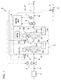
- FIG 1 is a block drawing that shows the outline constitution of a turbo compression device S (gas compression device) of the present embodiment.
- the turbo compression device S of the present embodiment is provided with an inlet guide vane 1 (flow rate adjusting means), a gas compression portion 2, a first circulation and supply control valve 3 (circulation and supply means), a second circulation and supply control valve 4 (circulation and supply means), an exhaust control valve 5, a flow rate detector 6 (flow rate detecting means), a pressure detector 7 (pressure detecting means), and a control unit 8 (control means).
- the inlet guide vane 1 is for adjusting the flow rate of gas that is drawn into the gas compression portion 2, and is controlled by the control unit 8.
- the gas compression portion 2 has a constitution in which two (a plurality of) centrifugal compressors 21 and 22 (compression means) are arranged in series in the flow direction of the gas.
- the gas that is drawn into the gas compression portion 2 via the inlet guide vane 1 is first drawn into the centrifugal compressor 21 that is positioned on the upstream side (furthest upstream) with respect to the flow direction of the gas. That is, the inlet guide vane 1 adjusts the flow rate of gas that is drawn into the centrifugal compressor 21 that is positioned furthest upstream with respect to the gas flow direction.
- This inlet guide vane 1 imparts a twist to the gas in the same direction as the rotation direction of an impeller 21a (refer to FIG. 2 ) that the centrifugal compressor 21 is equipped with. Thereby, the workload of the impellor of the centrifugal compressor 21 is decreased.
- the inlet guide vane 1 As a substitute for the inlet guide vane 1, it is also possible to use a butterfly valve. In this case, the flow rate of the gas that is drawn in is adjusted by applying resistance to the gas without imparting a twist to the gas.
- the gas compression portion 2 is provided with two centrifugal compressors 21 and 22 (compression means) that are arranged in the gas flow direction, a motor 23 (drive means) that supplies rotation power to the impellers 21a and 22a that are provided in the centrifugal compressors 21 and 22, an intercooler 24 that cools the gas that is discharged from the centrifugal compressor 21 (hereinbelow referred to as the first centrifugal compressor 21) located on the upstream side with respect to the flow direction of the gas, and an aftercooler 25 that cools the gas that is discharged from the centrifugal compressor 22 (hereinbelow referred to as the second centrifugal compressor 22) located on the downstream side with respect to the flow direction of the gas.
- the first centrifugal compressor 21 located on the upstream side with respect to the flow direction of the gas
- an aftercooler 25 that cools the gas that is discharged from the centrifugal compressor 22 located on the downstream side with respect to the flow direction of the gas.
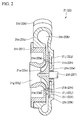
- FIG 2 is a cross-sectional view for describing the outline constitution of the first centrifugal compressor 21 and the second centrifugal compressor 22. Since the first centrifugal compressor 21 and the second centrifugal compressor 22 have the same constitution, in FIG. 2 , only one centrifugal compressor is shown. Also, in FIG 2 , reference numerals without parentheses refer to the first centrifugal compressor 21, while reference numerals with parentheses refer to the second centrifugal compressor 22.
- the centrifugal compressor 21 (22) is provided with a casing main body 21c (22c) that has a scroll flow path 21b (22b) of which one side opens and extends in the circumferential direction toward the portion in the vicinity of the inner peripheral edge, a gas discharge pipe 21d (22d) that is provided at a predetermined location of the casing main body 21c so as to continue to the scroll flow path 21b (22b), a rotor shaft 21f(22f) that rotatably passes through a seal member 21e (22e) that is provided in the center of the other wall portion of the casing main body 21c (22c), an impeller 21a (22a) that is positioned in the center in the inner portion of the casing main body 21c (22c) and that is coupled to the rotor shaft 21f(22f), a ring-shaped casing lid 21i (22i) that fits in the opening portion of the casing main body 21c (22c) so as to cover this impeller 21
- the rotor shaft 21f of the first centrifugal compressor 21 and the rotor shaft 22f of the second centrifugal compressor 22 are each connected with the motor 23 via a gearwheel acceleration mechanism. Then the impeller 21a (22a) rotates at a rotation speed corresponding to the output of the motor 23.
- the diffuser vane 21j (22j) is integrally formed with respect to the ring-shaped vane support seat 211 (221) that is installed in a cavity portion 21k (22k) that is provided so as to surround the impeller 21a (22a) in the interior of the casing main body 21c (22c).
- the flow path cross-sectional shape of the scroll flow path 21b (22b) is formed so as to become larger as the gas discharge pipe 21d (22d) is approached.
- a plurality of bypass flow passage holes 21m (22m) that are positioned between the impeller 21a (22a) and the diffuser vane 21j (22j) are formed in the casing lid 21i (22i).
- This bypass flow passage hole 21m (22m) is a flow passage for flowing gas from the outside of the centrifugal compressor 21 (22) toward the front edge side of the diffuser vane 21j (22j) of the diffuser 21h (22h).
- the plurality of bypass flow passage holes 21m (22m) are formed in the rotation direction of the impeller 21a (22a). That is, the diffuser 21h (22h) and the outside are connected by the plurality of bypass flow passages 21m (22m).
- centrifugal compressor 21 velocity energy is imparted by the rotatively driven impeller 21a (22a) to the gas that has flowed in from the gas inflow port 21g (22g). Then, the velocity energy that is imparted to the gas is converted to pressure energy by the diffuser vane 21j (22j). Thereby, the gas is compressed, and the compressed gas is discharged to the outside of the centrifugal compressor 21 (22) via the scroll flow path 21b (22b).
- FIG 1 shows the diffuser vane 21j (22j) and the scroll flow path 21b (22b) only on one side of the impeller 21a (22a) for convenience, they exist in reality along the entire periphery.
- the bypass flow passage holes 21m (22m) are formed at equal intervals between the impeller 21a (22a) and the diffuser vane 21j (22j) that exists along the entire periphery, and are constituted such that gas is uniformly supplied to each bypass flow passage hole 21m (22m).
- the motor 23 is connected to the impeller 21a and the impeller 22a, and the impeller 21a and impeller 22a are made to rotate at a constant rotational frequency.
- this kind of motor 23 it is possible to use an induction motor, for example.
- the first circulation and supply control valve 3 serves to enable circulation and supply of a portion or all of the gas that is discharged from the gas compression portion 2 to the bypass flow passage holes 21m of the first centrifugal compressor 21 (that is, between the impeller 21a and the diffuser vane 21j).
- the opening degree of the first circulation and supply control valve 3 is made to be controllable by the control unit 8. As the opening degree of the first circulation and supply control valve 3 is adjusted, the flow rate of gas that is supplied to the bypass flow passage holes 21m is adjusted.
- the second circulation and supply control valve 4 serves to enable circulation and supply of a portion or all of the gas that is discharged from the gas compression portion 2 to the bypass flow passage holes 22m of the second centrifugal compressor 22 (that is, between the impeller 22a and the diffuser vane 22j).
- the opening degree of the second circulation and supply control valve 4 is made to be controllable by the control unit 8. As the opening degree of the second circulation and supply control valve 4 is adjusted, the flow rate of gas that is supplied to the bypass flow passage holes 21m is adjusted.
- the exhaust control valve 5 serves to exhaust a portion or all of the gas that is discharged from the gas compression portion 2 to the outside of the turbo compression device S, and its opening and closing can be controlled by the control unit 8.
- the flow rate detector 6 has a measuring instrument that measures the flow of the gas that is discharged from the gas compression portion 2, and a transmitter that outputs the measurement result of the measuring instrument as a signal that shows the flow rate of the gas that has been discharged from the gas compression portion 2 (that is, the flow rate of the gas that has been discharged from the second centrifugal compressor 22).
- the pressure detector 7 has a measuring instrument that measures the pressure of the gas that is discharged from the gas compression portion 2 (that is, the pressure of the gas that has been discharged from the second centrifugal compressor 22), and a transmitter that outputs the measurement result of the measuring instrument as a signal that shows the pressure of the gas that has been discharged from the gas compression portion 2.
- the control unit 8 is electrically connected with the inlet guide vane 1 (or the butterfly valve), the motor 23 of the gas compression portion 2, the first circulation and supply control valve 3, the second circulation and supply control valve 4, the exhaust control valve 5, the flow rate detector 6, and the pressure detector 7.
- the gas that is drawn in from the outside via the filter f or the like is compressed and discharged by the gas compression portion 2. Then, of the gas that is discharged from the gas compression portion 2, the gas that excludes the gas that is supplied to the first centrifugal compressor 21 via the first circulation and supply control valve 3, the gas that is supplied to the second centrifugal compressor 22 via the second circulation and supply control valve 4, and the gas that is exhausted to the outside via the exhaust control valve 5 is supplied to the device at the demand end.
- the control unit 8 first compares the detection result of the pressure detector 7 and a set value that is determined in advance, and controls the inlet guide vane 1.
- the flow rate of the gas that is supplied from the turbo compression device S to the demand end device and the flow rate of the gas that the demand end device requires are shown to be the same.
- the balance between the gas flow rate that is supplied from the turbo compression device S to the demand end device and the gas flow rate that the demand end device requires is disturbed, and the pressure of the gas that is discharged from the gas compression portion 2 changes.
- control unit 8 compares the detection result of the pressure detector 7 and the set value that is determined in advance, and controls the inlet guide vane 1 so as to become the aforementioned desired pressure.
- the flow rate of the gas supplied from the turbo compression device S to the demand end device can be matched to the gas flow rate that the demand end device requires.
- the pressure of the gas after the gas compression portion 2 (the pressure of the gas that is discharged from the compression means that is located furthest downstream) relates to the flow rate of the gas supplied from the turbo compression device S to the demand end device. That is, controlling the inlet guide vane 1 based on the detection result of the pressure detector 7 is controlling the inlet guide vane 1 based on the flow rate of gas that is supplied from the turbo compression device S to the demand end device.
- control unit 8 checks the flow rate of the gas discharged from the gas compression portion 2, from the detection result of the flow rate detector 6. In addition to the detection result of the pressure detector 7, control of the inlet guide vane 1 may be performed using the detection result of the flow rate detector 6.
- the control unit 8 circulates and supplies a portion of the gas that is discharged from the gas compression portion 2 to the first centrifugal compressor 21 and/or the second centrifugal compressor 22.
- the control unit 8 controls the second circulation and supply control valve 4 to circulate and supply a portion of the gas that is discharged from the gas compression portion 2 between the impeller 22a and the diffuser vane 22j of the second centrifugal compressor 22 (that is, the diffuser 21h (22h).
- the control unit 8 controls the first circulation and supply control valve 3 to circulate and supply a portion of the gas that is discharged from the gas compression portion 2 between the impeller 21a and the diffuser vane 21j of the first centrifugal compressor 21 (that is, the diffuser 21h (22h).
- the set value that is set based on the surging limit is a value that matches the flow rate of the surging limit and the predetermined margin. Moreover, the flow rate of the surging limit shows the minimum limit gas flow rate at which surging does not occur in each centrifugal compressor S.
- the flow rate of the gas that is drawn into the first centrifugal compressor 21 corresponds to the opening of an inlet guide vane 1.
- the flow rate of the gas that is drawn into the second centrifugal compressor 22 corresponds to the opening of the inlet guide vane 1 and the opening of the first circulation and supply control valve 3.
- the opening of the first circulation and supply control valve 3 is controlled based on the opening of an inlet guide vane 1. For this reason, the flow rate of the gas drawn into the centrifugal compressors 21 and 22 is uniquely determined corresponding to the opening of an inlet guide vane 1.
- control unit 8 exhausts gas to the outside by opening the exhaust control valve 5 while maintaining the drawing in of the gas in the gas compression portion 2 via the inlet guide vane 1 in the case of the quantity of gas demanded by the demand end device being zero.
- control device 8 maintains the operation of the turbo compression device S at the minimum energy consumption without completely closing the inlet guide vane 1.
- the gas that is drawn in from the outside is drawn into the turbo compression device S via the inlet guide vane 1, and is drawn into the gas compression portion 2.
- the gas is compressed in the first centrifugal compressor 21, is subsequently cooled by the intercooler 24, and is further compressed in the second centrifugal compressor 22, and thereafter cooled and discharged by the aftercooler 25.
- the gas that is discharged from the gas compression portion 2 is distributed corresponding to the opening of the first circulation and supply control valve 3, the second circulation and supply control valve 4, and the exhaust control valve 5, with the remainder being supplied to the demand end device.
- the gas that is distributed by the first circulation and supply control valve 3 is supplied as required between the impeller 21a and the diffuser vane 21j of the first centrifugal compressor 21. Also, the gas that is distributed by the second circulation and supply control valve 4 is supplied between the impeller 22a and the diffuser vane 22j of the second centrifugal compressor 22. Also, the gas that is distributed by the exhaust control valve 5 is exhausted to the outside.
- (flow rate %) refers to the weight flow rate % of the gas, and the flow rate at each place is assumed to be 100 flow rate % in the case of the inlet guide vane 1 being opened to its maximum extent.
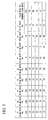
- FIG 3 is a table that shows the (flow rate %) at each position A to I in correspondence with the (flow rate %) of the gas supplied to the demand end device.
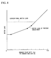
- FIG. 4 is a graph that shows the relationship between the demand flow amount to the demand end device and the motor load.
- A is the upstream side position of the inlet guide vane 1
- B is the position between the inlet guide vane 1 and the first centrifugal compressor
- C is the position between the centrifugal compressor 21 and the second centrifugal compressor
- D is the position on the downstream side of the second centrifugal compressor
- E is the position on the downstream side of the second centrifugal compressor 22 and the position after the removal of the gas to be exhausted via the exhaust control value 5
- F is the position on the downstream side of the second centrifugal compressor 22 and is the position that is divided to the side of the first circulation and supply control valve 3 and the second circulation and supply control valve 4
- G is the position on the downstream side of the of the exhaust control valve
- H is the position between the first circulation and supply control valve 3 and the first centrifugal compressor
- I is the position between the second circulation and supply control valve 4 and the second centrifugal compressor
- J is the position just before the demand end.
- the set value based on the surging limit of the first centrifugal compressor 21 is 60 flow rate %
- the set value based on the surging limit of the second centrifugal compressor 22 is 70 flow rate %.
- the inlet guide vane 1 is opened to a maximum, and thereby the flow rate at A to D becomes 100 flow rate %.
- the control unit 8 in the case of the demand flow rate of the demand end device being 100 flow rate %, makes the output of the motor 23 100% and puts the first circulation and supply control valve 3, the second circulation and supply control valve 4, and the exhaust control valve 5 in a closed state.
- the flow rate at E becomes 100 flow rate %
- the flow rates at F to I become 0 flow rate %. That is, in the case of the demand flow rate of the demand end device being 100 flow rate %, all of the gas is supplied to the demand end device, and there is no circulation and supply to the first centrifugal compressor 21 and the second centrifugal compressor 22.
- the load of the motor 23 also becomes 100% as shown in FIG. 4 .
- the control unit 8 restricts the opening of the inlet guide vane 1 to make the flow rate at A 70 flow rate %.
- the flow rate at B to D also becomes 70 flow rate %.
- the control unit 8 in the case of the demand flow rate of the demand end device being 70 flow rate %, puts the first circulation and supply control valve 3, the second circulation and supply control valve 4, and the exhaust control valve 5 in a closed state.
- the flow rate at E becomes 70 flow rate %
- the flow rate at F to I becomes 0 flow rate %. That is, in the case of the demand flow rate of the demand end device being 70 flow rate %, all of the gas is supplied to the demand end device, and there is no circulation and supply to the first centrifugal compressor 21 and the second centrifugal compressor 22.
- the load of the motor 23 also becomes 70% as shown in FIG 4 .
- the control unit 8 restricts the opening of the inlet guide vane 1 to make the flow rate at A 60 flow rate %.
- the control unit 8 opens up the second circulation and supply control valve 4 so that a 10 flow rate % portion of the gas that is discharged from the gas compression portion 2 is circulated and supplied to the second centrifugal compressor 22.
- the first circulation and supply control valve 3 and the exhaust control valve 5 remain closed.
- the flow rate at B and C becomes 60 flow rate %
- the flow rate at D and E becomes 70 flow rate %
- the flow rate at F and I becomes 10 flow rate %
- the flow rate at G and H becomes 0 flow rate %.
- the control unit 8 restricts the opening of the inlet guide vane 1 to make the flow rate at A 50 flow rate %.
- the control unit 8 opens up the first circulation and supply control valve 3 and the second circulation and supply control valve 4 so that, of the gas that is discharged from the gas compression portion 2, 10 flow rate % is circulated and supplied to the first centrifugal compressor 21 and a 10 flow rate % portion is circulated and supplied to the second centrifugal compressor 22.
- the exhaust control valve 5 remains closed.
- the flow rate at B becomes 50 flow rate %
- the flow rate at C becomes 60 flow rate %
- the flow rate at D and E becomes 70 flow rate %
- the flow rate at F becomes 20 flow rate %
- the flow rate at G becomes 0 flow rate %
- the flow rate at H and I becomes 10 flow rate %.
- the flow rate in the diffuser 21h becomes 60 flow rate %
- the flow rate in the diffuser 22h becomes 70 flow rate %, it is possible to suppress the occurrence of surging in the first centrifugal compressor 21 and the second centrifugal compressor 22.
- the load on the motor 23 is further reduced compared to the case of the demand flow rate of the demand end device being 60 flow rate % as shown in FIG. 4 .
- the control unit 8 restricts the opening of the inlet guide vane 1 to make the flow rate at A 10 flow rate %.
- the control unit 8 opens up the first circulation and supply control valve 3 and the second circulation and supply control valve 4 so that, of the gas that is discharged from the gas compression portion 2, 50 flow rate % is circulated and supplied to the first centrifugal compressor 21 and a 10 flow rate % portion is circulated and supplied to the second centrifugal compressor 22.
- the exhaust control valve 5 remains closed.
- the flow rate at B becomes 10 flow rate %
- the flow rate at C becomes 60 flow rate %
- the flow rate at D and E becomes 70 flow rate %
- the flow rate at F becomes 60 flow rate %
- the flow rate at G becomes 0 flow rate %
- the flow rate at H becomes 50 flow rate %
- the flow rate at I becomes 10 flow rate %.
- the flow rate in the diffuser 21h becomes 60 flow rate %
- the flow rate in the diffusers 22h becomes 70 flow rate %
- the load on the motor 23 is further reduced compared to the case of the demand flow rate of the demand end device being 50 flow rate % as shown in FIG 4 .
- the control unit 8 similarly to the case of the demand flow rate of the demand end device being 10 flow rate %, opens up the first circulation and supply control valve 3 and the second circulation and supply control valve 4 so that, of the gas that is discharged from the gas compression portion 2, 50 flow rate % is circulated and supplied to the first centrifugal compressor 21 and a 10 flow rate % portion is circulated and supplied to the second centrifugal compressor 22. Then, it is opened via the exhaust control valve 5, and the output of the motor 23 is maintained at 10%.
- the flow rate at B becomes 10 flow rate %
- the flow rate at C and E becomes 60 flow rate %
- the flow rate at D becomes 70 flow rate %
- the flow rate at F becomes 60 flow rate %
- the flow rate at G becomes 10 flow rate %
- the flow rate at H becomes 50 flow rate %
- the flow rate at I becomes 10 flow rate %.
- the circulation and supply of gas is started in stages from the second centrifugal compressor 22 that is positioned furthest downstream to the first centrifugal compressor 21 that is upstream.
- the flow rate of gas that the turbo compression device S draws in is controlled in proportion to the gas demand flow rate (demand amount) of the demand end device. That is, in the case of the gas demand flow rate of the demand end device having decreased, the flow rate of the gas that the turbo compression device S draws in is reduced in proportion to this amount of decrease.
- each centrifugal compressor 21 and 22 in the case of the flow rate of the gas that is drawn in falling below a set value that is set based on the surging limit in the centrifugal compressor 21 and 22, a portion of the gas that is discharged from the gas compression portion 2 in the centrifugal compressors 21 and 22 concerned is circulated and supplied to the diffusers 21h and 22h of the centrifugal compressors 21 and 22, respectively, so that surging is suppressed.
- the gas that is circulated and supplied flows to the diffusers 21h and 22h without being supplied to the impellers 21a and 22a. For this reason, it is possible to supply gas at a sufficient flow rate to the diffusers 21h and 22h without increasing the load on the impellers 21a and 22a, and it is possible to suppress the occurrence of surging without increasing the load on the motor. That is, however low the flow rate of the gas that is drawn into the first centrifugal compressor 21, it is possible to cause a flow of gas with a flow rate that enables suppression of surging to the diffusers 21h and 22h of the respective centrifugal compressors 21 and 22.
- the turbo compression device that compresses gas by the centrifugal compressors 21 and 22 that are arranged in a plurality in series in the flow direction of the gas, it is possible to reduce energy consumption by sufficiently reducing the load of the motor while suppressing the occurrence of surging in the centrifugal compressors 21 and 22.
- turbo compression device and the method of controlling the turbo compression device of the present embodiment in the case of the gas demand flow rate of the demand end device being zero, in addition to maintaining the drawing in of the gas in the gas compression portion 2, a portion of the gas that is discharged from the gas compression portion 2 (that gas that is not circulated and supplied among the gas that is discharged from the gas compression portion 2) is exhausted without supplying to the demand end device. For this reason, even in the case of the gas demand flow rate of the demand end device being zero, it is possible to maintain the operation of the turbo compression device S with minimal energy consumption without completing closing the inlet guide vane 1. Therefore, it is possible to reopen the supply quickly in the case of the supply of gas to the demand end device once again being required.
- a value that relates to the centrifugal compressor 21 and the centrifugal compressor 22 that is stored in advance in the control unit 8 is made a value that matches the flow rate at the surging limit in the centrifugal compressors 21 and 22 and a predetermined margin. For this reason, after imparting a margin to the flow rate of the surging limit, since the gas is circulated and supplied to the centrifugal compressors 21 and 22, it is possible to reliably suppress the occurrence of surging.
- the centrifugal compressor that is positioned on the downstream side with respect to the gas flow direction has a smaller flow rate coefficient
- gas is circulated and supplied first to the centrifugal compressor that is positioned on the downstream side.
- the margin in the set value that relates to the first centrifugal compressor 21 to be greater than the margin in the set value that relates to the second centrifugal compressor 22
- turbo compression device being provided with two centrifugal compressors.
- the present invention is not limited to this, and there may be three or more centrifugal compressors.
- a constitution may be adopted that circulates and supplies gas simultaneously to a number of centrifugal compressors.
- the circulation and supply of gas may be started in stages in the order of a centrifugal compressor X3 that is furthest downstream, a centrifugal compressor X2 that is mid stream, and a centrifugal compressor X1 that is furthest upstream, as shown in the schematic drawing of FIG.
- the circulation and supply may be simultaneously started to the centrifugal compressor X3 that is furthest downstream, the centrifugal compressor X2 that is mid stream, and the circulation and supply may be subsequently started to the centrifugal compressor X1 that is furthest upstream, and as shown in the schematic drawing of FIG 7 , the circulation and supply may be simultaneously started to the centrifugal compressor X2 that is mid stream and the centrifugal compressor X1 that is furthest upstream after starting the circulation and supply to the centrifugal compressor X3 that is furthest downstream.
- the pressure means that is furthest downstream has a small flow rate coefficient and enters a surge first, in any event the circulation and supply to the centrifugal compressor that is located on the downstream side is started first, and thereafter the circulation and supply to the centrifugal compressor that is located on the upstream side is started.
- the constitution was described of directly measuring the flow rate of the gas discharged from the gas compression portion 2 by the flow rate detector 6 and, based on this measurement result, the control unit 8 acquiring the demand amount of gas of the demand end device.
- the present invention is not limited to this, and in place of the flow rate detector 6, the current consumption or power consumption of the motor 23 may be measured, and thereby the flow rate of the gas discharged from the gas compression portion 2 may be indirectly measured. With such a constitution, it is possible to acquire the demand amount of gas of the demand end device based on the measurement result.
- the present invention is not limited thereto, and it is possible to use an axial flow compressor as the compression means of the present invention.
- the present invention is not limited thereto, and it is possible to use an engine, such as a diesel engine, or a turbine, such as a steam turbine, as the driving means of the present invention. In such a case, it is possible to acquire the demand amount of gas of the demand end device by detecting the engine or turbine torque in place of the flow rate detector 6.
- the constitution was described in which the rotational frequency of the motor 23 is constant.
- the present invention is not limited thereto, and for example the rotational frequency of the motor 23 may be changed in accordance with the intake amount of gas of the gas compression portion 2. In such a case, an inverter motor is often used as the motor 23.
- the constitution was described in which the diffusers 21h and 22h are disposed just after the impellers 21a and 22a, respectively, and the gas is circulated and supplied to the diffusers 21h and 22h.
- the present invention is not limited thereto, and for example, in the case of a throttle channel or the like existing between the impeller 21a and 22a and the diffuser 21h and 22h, it is possible to circulate and supply gas to the diffusers 21h and 22h, or between the diffusers 21h and 22h and the impellers 21a and 22a (that is, the throttle channel).
- the present invention can be applied to a multi-stage compressor with a single shaft and multiple stages, in which a plurality of centrifugal compressors are disposed in multiple stages on a single shaft, and a multi-stage compressor with multiple shafts and multiple stages, in which a centrifugal compressor is disposed on each shaft of the plurality of shafts via a gear type speed increasing mechanism.
- gas of the present invention for example it is possible to use air, nitrogen, oxygen, or carbon dioxide gas.
- the gas compression device and a method of controlling the gas compression device of the present invention while suppressing the occurrence of surging in a centrifugal compressor, it is possible to sufficiently reduce the load of a motor, and it is possible to reduce the consumption of energy.
Landscapes
- Engineering & Computer Science (AREA)
- Mechanical Engineering (AREA)
- General Engineering & Computer Science (AREA)
- Life Sciences & Earth Sciences (AREA)
- Sustainable Development (AREA)
- Physics & Mathematics (AREA)
- Geometry (AREA)
- Control Of Positive-Displacement Air Blowers (AREA)
- Structures Of Non-Positive Displacement Pumps (AREA)
Abstract
In a gas compression device that compresses gas by a compression means that is arranged in a plurality in series with respect to the flow direction of the gas, controlling the flow rate of the gas that is drawn into the gas compression portion in accordance with the demand amount of the gas of the demand end and, in the case of the flow rate of each compression means falling below a set value that is set based on the surging value, circulating and supplying at least a portion of the gas that is discharged from the gas compression portion to a diffuser of the compression means. For this reason, it is possible to sufficiently reduce the load of the driving means while suppressing the occurrence of surging in the compression means, and it is possible to reduce the consumption of energy.
Description
- The present invention relates to a gas compression device that is provided with a plurality of compression means that are driven by a single drive means, and a method for controlling the gas compression device.
- Priority is claimed on Japanese Patent Application No.
2007-188093, filed July 19, 2007 - A turbo compression device (gas compression device) that is provided with a plurality of centrifugal compressors (compression means) that are linked by a shaft that is driven by a single motor (drive means) has conventionally been employed.
- In such a turbo compression device, the plurality of centrifugal compressors are arranged in series in the flow direction of the gas, so that the gas is gradually compressed in each centrifugal compressor.
- In a device (demand end) to which gas that is compressed (hereinbelow referred to as compressed gas) is supplied from the turbo compression device in a typical factory, the amount of compressed gas that is required (demand amount) changes with time. That is, the amount of the compressed gas that is supplied from the turbo compression device to a device at the demand end changes with time.
- It is conceivable to respond to a decrease in the demand amount of the compressed gas by a method that decreases the amount of compressed gas by decreasing the intake amount of gas to the turbo compression device, and a method that always compresses a fixed amount of gas and supplies only the required amount to the device at the demand end and exhausts the remainder, but it is preferable to respond by a method that decreases the amount of compressed gas that is capable of reducing energy consumption in the turbo compression device (that is, capable of reducing the load on the motor).
- In order to decrease the amount of compressed gas, it is necessary to decrease the flow rate of gas that flows in the turbo compression device. However, decreasing the flow rate of gas that flows in a centrifugal compressor beyond a certain limit gives rise to surging. In greater detail, when gas that is accelerated by an impeller in a centrifugal compressor is decelerated by a diffuser, the flow of this gas stalls, and this becomes a trigger of an occurrence of surging.
- Therefore, in a conventional turbo compression device, by using a method that avoids surging in a centrifugal compressor such as disclosed in
Patent Documents 1 to 4, the load on the motor is reduced while suppressing surging in the centrifugal compressor. - [Patent Document 1] Japanese Examined Patent Application Publication No.
H02-61640 - [Patent Document 2] Japanese Examined Patent Application Publication No.
H02-59317 - [Patent Document 3] Japanese Unexamined Utility Model Application Publication No.
S59-99196 - [Patent Document 4] Japanese Unexamined Patent Application Publication No.
H10-252696 - However, in a conventional centrifugal compressor, even if the art that is disclosed in
Patent Documents 1 to 4 is employed, sufficiently suppressing surging is difficult in an environment in which the flow rate of the gas that is drawn into the centrifugal compressor is low, and it is not possible to decrease the flow rate of gas that is drawn into the centrifugal compressor to 60 to 70% or less. For this reason, it has not been possible to reduce the load on the motor to 60 to 70% or less. - The present invention was achieved in view of the above circumstances, and has as its object, in a gas compression device that compresses gas by a plurality of compression means that are arranged in series with respect to the gas flow direction, to reduce the energy consumption by sufficiently reducing the load of a drive means while suppressing the occurrence of surging in the compression means.
- In order to achieve the aforementioned object, the gas compression device that is the first embodiment of the present invention is a gas compression device that arranges a plurality of compression means provided with impellers that impart velocity energy to a gas, and a diffuser that converts the velocity energy to pressure energy in series in the flow direction of gas, and supplies the gas that is compressed via the plurality of the compression means to a predetermined demand end, provided with a drive means that supplies power to the impeller; a flow rate adjusting means that adjusts the flow rate of the gas that is drawn into the compression means that is positioned furthest upstream with respect to the flow direction of the gas; a circulation and supply means that is capable of circulating and supplying at least a portion of the gas that is discharged from the compression means that is positioned furthest downstream with respect to the flow direction of the gas to the diffuser or is positioned between the diffuser and the impeller of each compression means, and a control means that controls at least the drive means, the flow rate adjusting means, and the circulation and supply means, in which the control means controls the flow rate adjusting means in accordance with a demand amount of the gas of the demand end, and in each compression means, in the case of the flow rate of the gas that is drawn in falling below a set value that is set based on a surging limit in the compression means, controls the circulation and supply means to circulate and supply a portion of the gas in the compression means.
- According to this gas compression device, the flow rate adjusting means is controlled in accordance with the demand amount of gas of the demand end. That is, in the case of the demand amount of gas of the demand end decreasing, the flow rate of gas that is drawn into the gas compression device is reduced in accordance with this decrement.
- In each compression means, in the case of the flow rate of the gas that is drawn in falling below a set value that is set based on a surging limit in the compression means, a portion of the gas in the compression means is circulated and supplied to the diffuser or between the diffuser and the impeller of each compression means.
- The gas compression device may be provided with a pressure detecting means that detects the pressure of the gas that is discharged from the compression means that is positioned furthest downstream, and a flow rate detecting means that detects the flow rate of the gas that is discharged from the compression means that is positioned furthest downstream, and the control means may perform control of the flow rate adjusting means with at least the detection result of the pressure detecting means serving as the demand amount of the gas of the demand end, among the pressure detecting means and the flow rate detecting means.
- The control means may start circulation and supply of the gas by the circulation and supply means in stages from the compression means that is positioned furthest downstream toward the upstream compression means.
- The set value may be a value that matches the flow rate of the surging limit in the compression means and a predetermined margin.
- The control means, in the case of the demand amount of the gas of the demand end being zero, may maintain the intake of the gas in the compression means that is positioned furthest upstream with respect to the flow direction of the gas, and exhaust a portion of the gas that is discharged from the compression means that is positioned furthest downstream with respect to the flow direction of the gas without supplying it to the demand end.
- Next, a method of controlling a gas compression device that is the second embodiment of the present invention is a method of controlling a gas compression device that arranges a plurality of compression means provided with an impeller that imparts velocity energy to a gas and a diffuser that converts the velocity energy to pressure energy in series in the flow direction of gas, and supplies the gas that is compressed via the plurality of the compression means to a predetermined demand end, comprising the steps of: adjusting the flow rate of gas that is drawn into the compression means that is positioned furthest upstream with respect to the flow direction of the gas in accordance with a demand amount of the gas at the demand end, and in each compression means, circulating and supplying at least a portion of the gas that is discharged from the compression means that is positioned furthest downstream with respect to the flow direction of the gas to the diffuser or between the diffuser and the impeller of each compression means in the case of the flow rate of the gas that is drawn in falling below a set value that is set based on a surging limit in the compression means.
- According to this method of controlling a gas compression device, in accordance with a demand amount of the gas at the demand end, the flow rate of the gas that is drawn into the gas compression device is controlled. That is, in the case of the demand amount of the gas at the demand end device having decreased, the flow rate of the gas that is drawn into the gas compression device is reduced in proportion to this decrement.
- In each compression means, in the case of the flow rate of the gas that is drawn in falling below a set value that is set based on a surging limit in the compression means, in the compression means, a portion of the gas that is discharged from the compression means that is positioned furthest downstream is circulated and supplied to the diffuser or between the diffuser and the impeller of each compression means.
- Detecting the pressure and the flow rate of the gas that is discharged from the compression means that is positioned furthest downstream and, among the detection result, controlling the flow rate of the gas that is drawn into the compression means that is positioned furthest upstream may be performed with at least the pressure serving as the demand amount of the gas at the demand end.
- The circulation and supply of the gas may be started in stages from the compression means that is positioned furthest downstream toward the upstream compression means.
- The set value may be a value that matches the flow rate of the surging limit in the compression means and a predetermined margin.
- In the case of the demand amount of the gas at the demand end being zero, maintaining the intake of the gas in the compression means that is positioned furthest upstream with respect to the flow direction of the gas, and exhausting a portion of the gas that is discharged from the compression means that is positioned furthest downstream with respect to the flow direction of the gas without supplying it to the demand end may be performed.
- According to the gas compression device and the method of controlling the gas compression device of the present invention, the flow rate of gas that is drawn into the gas compression device is controlled in accordance with the demand amount of gas at the demand end. That is, in the case of the demand amount of the gas at the demand end device having decreased, the flow rate of the gas that is drawn into the gas compression device is reduced in proportion to this decrement.
- In each compression means, in the case of the flow rate of the gas that is drawn in falling below a set value that is set based on a surging limit in the compression means, in the compression means, a portion of the gas that is discharged from the compression means that is positioned furthest downstream is circulated and supplied to the diffuser or between the diffuser and the impeller of each compression means.
- Here, the gas that is circulated and supplied flows to the diffuser without being supplied to the impeller. For this reason, it is possible to supply gas of a sufficient flow rate to the diffuser without increasing the load on the impeller, and it is possible to suppress the occurrence of stalling and the occurrence of surging without increasing the load to the drive means. That is, however low the flow rate of the gas that is drawn into each compression means, it is possible to cause a flow of gas with a flow rate that enables suppression of surging to the diffuser of the compression means.
- Accordingly, according to the present invention, in a gas compression device that compresses gas by a plurality of compression means that are provided in series with respect to the flow direction of gas, it is possible to reduce energy consumption by sufficiently reducing the load of the drive means while suppressing the occurrence of surging in the compression means.
-
-
FIG 1 is a block drawing that shows the outline constitution of a turbo compression device that is one embodiment of the present invention. -
FIG 2 is a cross-sectional view of a centrifugal compressor that is provided in the turbo compression device that is one embodiment of the present invention. -
FIG. 3 is a table that shows the flow distribution of gas in the turbo compression device that is one embodiment of the present invention. -
FIG. 4 is a graph that shows the load changes of a motor that is provided in the turbo compression device that is one embodiment of the present invention. -
FIG 5 is a schematic drawing that shows a modification of the turbo compression device that is one embodiment of the present invention. -
FIG. 6 is a schematic drawing that shows a modification of the turbo compression device that is one embodiment of the present invention. -
FIG. 7 is a schematic drawing that shows a modification of the turbo compression device that is one embodiment of the present invention. - 1 inlet guide vane (flow rate adjusting means, 2 gas compression portion, 21 first centrifugal compressor (compression means), 22 second centrifugal compressor (compression means), 23 motor (drive means), 3 first circulation and supply control valve (circulation and supply means), 4 second circulation and supply control valve (circulation and supply means), 5 discharge valve, 6 flow rate detector (flow rate detecting means), 7 pressure detector (pressure detecting means), 8 control device (control means), 21a, 22a impeller, 21h, 22h diffuser, s turbo compression device (gas compression device)
- Hereinbelow, an embodiment of a gas compression device and a method of controlling the gas compression device according to the present invention shall be described with reference to the drawings. In the following drawings, the scale of each member shall be suitably changed in order to make each member a recognizable size.
-
FIG 1 is a block drawing that shows the outline constitution of a turbo compression device S (gas compression device) of the present embodiment. - As shown in the drawings, the turbo compression device S of the present embodiment is provided with an inlet guide vane 1 (flow rate adjusting means), a
gas compression portion 2, a first circulation and supply control valve 3 (circulation and supply means), a second circulation and supply control valve 4 (circulation and supply means), an exhaust control valve 5, a flow rate detector 6 (flow rate detecting means), a pressure detector 7 (pressure detecting means), and a control unit 8 (control means). - The
inlet guide vane 1 is for adjusting the flow rate of gas that is drawn into thegas compression portion 2, and is controlled by thecontrol unit 8. Although described in full detail below, thegas compression portion 2 has a constitution in which two (a plurality of)centrifugal compressors 21 and 22 (compression means) are arranged in series in the flow direction of the gas. The gas that is drawn into thegas compression portion 2 via theinlet guide vane 1 is first drawn into thecentrifugal compressor 21 that is positioned on the upstream side (furthest upstream) with respect to the flow direction of the gas. That is, theinlet guide vane 1 adjusts the flow rate of gas that is drawn into thecentrifugal compressor 21 that is positioned furthest upstream with respect to the gas flow direction. - This
inlet guide vane 1 imparts a twist to the gas in the same direction as the rotation direction of animpeller 21a (refer toFIG. 2 ) that thecentrifugal compressor 21 is equipped with. Thereby, the workload of the impellor of thecentrifugal compressor 21 is decreased. - As a substitute for the
inlet guide vane 1, it is also possible to use a butterfly valve. In this case, the flow rate of the gas that is drawn in is adjusted by applying resistance to the gas without imparting a twist to the gas. - The
gas compression portion 2 is provided with twocentrifugal compressors 21 and 22 (compression means) that are arranged in the gas flow direction, a motor 23 (drive means) that supplies rotation power to theimpellers centrifugal compressors intercooler 24 that cools the gas that is discharged from the centrifugal compressor 21 (hereinbelow referred to as the first centrifugal compressor 21) located on the upstream side with respect to the flow direction of the gas, and anaftercooler 25 that cools the gas that is discharged from the centrifugal compressor 22 (hereinbelow referred to as the second centrifugal compressor 22) located on the downstream side with respect to the flow direction of the gas. - The first
centrifugal compressor 21 and the secondcentrifugal compressor 22 compress and discharge the gas that is drawn in.FIG 2 is a cross-sectional view for describing the outline constitution of the firstcentrifugal compressor 21 and the secondcentrifugal compressor 22. Since the firstcentrifugal compressor 21 and the secondcentrifugal compressor 22 have the same constitution, inFIG. 2 , only one centrifugal compressor is shown. Also, inFIG 2 , reference numerals without parentheses refer to the firstcentrifugal compressor 21, while reference numerals with parentheses refer to the secondcentrifugal compressor 22. - As shown in
FIG. 2 , the centrifugal compressor 21 (22) is provided with a casing main body 21c (22c) that has a scroll flow path 21b (22b) of which one side opens and extends in the circumferential direction toward the portion in the vicinity of the inner peripheral edge, a gas discharge pipe 21d (22d) that is provided at a predetermined location of the casing main body 21c so as to continue to the scroll flow path 21b (22b), a rotor shaft 21f(22f) that rotatably passes through a seal member 21e (22e) that is provided in the center of the other wall portion of the casing main body 21c (22c), an impeller 21a (22a) that is positioned in the center in the inner portion of the casing main body 21c (22c) and that is coupled to the rotor shaft 21f(22f), a ring-shaped casing lid 21i (22i) that fits in the opening portion of the casing main body 21c (22c) so as to cover this impeller 21a (22a) and that forms a diffuser 21h (22h) that continues from a gas inflow port 21g (22g) that heads from the outer portion to the distal end of the impeller 21a (22a) and from the circumferential edge portion of the impeller 21a (22a) to the scroll flow path 21b (22b), and a plurality of diffuser vanes 21j (22j) that are disposed at equal intervals in the circumferential direction in the diffuser 21h (22h). - The
rotor shaft 21f of the firstcentrifugal compressor 21 and therotor shaft 22f of the secondcentrifugal compressor 22 are each connected with themotor 23 via a gearwheel acceleration mechanism. Then theimpeller 21a (22a) rotates at a rotation speed corresponding to the output of themotor 23. - Also, the
diffuser vane 21j (22j) is integrally formed with respect to the ring-shaped vane support seat 211 (221) that is installed in acavity portion 21k (22k) that is provided so as to surround theimpeller 21a (22a) in the interior of the casingmain body 21c (22c). - Also, the flow path cross-sectional shape of the
scroll flow path 21b (22b) is formed so as to become larger as thegas discharge pipe 21d (22d) is approached. - Moreover, in the centrifugal compressor 21 (22), a plurality of bypass flow passage holes 21m (22m) that are positioned between the
impeller 21a (22a) and thediffuser vane 21j (22j) are formed in the casing lid 21i (22i). This bypassflow passage hole 21m (22m) is a flow passage for flowing gas from the outside of the centrifugal compressor 21 (22) toward the front edge side of thediffuser vane 21j (22j) of thediffuser 21h (22h). The plurality of bypass flow passage holes 21m (22m) are formed in the rotation direction of theimpeller 21a (22a). That is, thediffuser 21h (22h) and the outside are connected by the plurality ofbypass flow passages 21m (22m). - In this kind of centrifugal compressor 21 (22), velocity energy is imparted by the rotatively driven
impeller 21a (22a) to the gas that has flowed in from thegas inflow port 21g (22g). Then, the velocity energy that is imparted to the gas is converted to pressure energy by thediffuser vane 21j (22j). Thereby, the gas is compressed, and the compressed gas is discharged to the outside of the centrifugal compressor 21 (22) via thescroll flow path 21b (22b). Then, the gas that flows in via the bypass flow passage holes 21m (22m), without being supplied to theimpeller 21a (22a), is supplied to thediffuser vane 21j (22j) along with the gas to which the velocity energy has been imparted by theimpeller 21a (22a). - Although
FIG 1 shows thediffuser vane 21j (22j) and thescroll flow path 21b (22b) only on one side of theimpeller 21a (22a) for convenience, they exist in reality along the entire periphery. The bypass flow passage holes 21m (22m) are formed at equal intervals between theimpeller 21a (22a) and thediffuser vane 21j (22j) that exists along the entire periphery, and are constituted such that gas is uniformly supplied to each bypassflow passage hole 21m (22m). - Returning to
FIG. 1 , themotor 23 is connected to theimpeller 21a and theimpeller 22a, and theimpeller 21a andimpeller 22a are made to rotate at a constant rotational frequency. As this kind ofmotor 23, it is possible to use an induction motor, for example. - The first circulation and
supply control valve 3 serves to enable circulation and supply of a portion or all of the gas that is discharged from thegas compression portion 2 to the bypass flow passage holes 21m of the first centrifugal compressor 21 (that is, between theimpeller 21a and thediffuser vane 21j). - The opening degree of the first circulation and
supply control valve 3 is made to be controllable by thecontrol unit 8. As the opening degree of the first circulation andsupply control valve 3 is adjusted, the flow rate of gas that is supplied to the bypassflow passage holes 21m is adjusted. - The second circulation and
supply control valve 4 serves to enable circulation and supply of a portion or all of the gas that is discharged from thegas compression portion 2 to the bypass flow passage holes 22m of the second centrifugal compressor 22 (that is, between theimpeller 22a and thediffuser vane 22j). - The opening degree of the second circulation and
supply control valve 4 is made to be controllable by thecontrol unit 8. As the opening degree of the second circulation andsupply control valve 4 is adjusted, the flow rate of gas that is supplied to the bypassflow passage holes 21m is adjusted. - The exhaust control valve 5 serves to exhaust a portion or all of the gas that is discharged from the
gas compression portion 2 to the outside of the turbo compression device S, and its opening and closing can be controlled by thecontrol unit 8. - The
flow rate detector 6 has a measuring instrument that measures the flow of the gas that is discharged from thegas compression portion 2, and a transmitter that outputs the measurement result of the measuring instrument as a signal that shows the flow rate of the gas that has been discharged from the gas compression portion 2 (that is, the flow rate of the gas that has been discharged from the second centrifugal compressor 22). - The pressure detector 7 has a measuring instrument that measures the pressure of the gas that is discharged from the gas compression portion 2 (that is, the pressure of the gas that has been discharged from the second centrifugal compressor 22), and a transmitter that outputs the measurement result of the measuring instrument as a signal that shows the pressure of the gas that has been discharged from the
gas compression portion 2. - The
control unit 8 is electrically connected with the inlet guide vane 1 (or the butterfly valve), themotor 23 of thegas compression portion 2, the first circulation andsupply control valve 3, the second circulation andsupply control valve 4, the exhaust control valve 5, theflow rate detector 6, and the pressure detector 7. - In this kind of turbo compression device S of the present embodiment, the gas that is drawn in from the outside via the filter f or the like is compressed and discharged by the
gas compression portion 2. Then, of the gas that is discharged from thegas compression portion 2, the gas that excludes the gas that is supplied to the firstcentrifugal compressor 21 via the first circulation andsupply control valve 3, the gas that is supplied to the secondcentrifugal compressor 22 via the second circulation andsupply control valve 4, and the gas that is exhausted to the outside via the exhaust control valve 5 is supplied to the device at the demand end. - The
control unit 8 first compares the detection result of the pressure detector 7 and a set value that is determined in advance, and controls theinlet guide vane 1. - Described in greater detail, in the case of the pressure of the gas after the
gas compression portion 2 being a desired pressure set value that is set in advance, the flow rate of the gas that is supplied from the turbo compression device S to the demand end device and the flow rate of the gas that the demand end device requires are shown to be the same. In the case of the gas flow rate that the demand end device requires having changed, the balance between the gas flow rate that is supplied from the turbo compression device S to the demand end device and the gas flow rate that the demand end device requires is disturbed, and the pressure of the gas that is discharged from thegas compression portion 2 changes. - For this reason, the
control unit 8 compares the detection result of the pressure detector 7 and the set value that is determined in advance, and controls theinlet guide vane 1 so as to become the aforementioned desired pressure. As a result, the flow rate of the gas supplied from the turbo compression device S to the demand end device can be matched to the gas flow rate that the demand end device requires. - Thus, the pressure of the gas after the gas compression portion 2 (the pressure of the gas that is discharged from the compression means that is located furthest downstream) relates to the flow rate of the gas supplied from the turbo compression device S to the demand end device. That is, controlling the
inlet guide vane 1 based on the detection result of the pressure detector 7 is controlling theinlet guide vane 1 based on the flow rate of gas that is supplied from the turbo compression device S to the demand end device. - When the detection result of the pressure detector 7 has become the desired pressure, the
control unit 8 checks the flow rate of the gas discharged from thegas compression portion 2, from the detection result of theflow rate detector 6. In addition to the detection result of the pressure detector 7, control of theinlet guide vane 1 may be performed using the detection result of theflow rate detector 6. - When rapid control of the
inlet guide vane 1 is not required, it is also possible to directly measure the flow rate of the gas that is supplied to the demand end device, and to change this measuring result to the detection result of the pressure detector 7. - As a result of the control of the
inlet guide vane 1, in the case of the flow rate of the gas that is drawn into thecentrifugal compressors centrifugal compressors supply control valve 3 and/or the second circulation andsupply control valve 4, thecontrol unit 8 circulates and supplies a portion of the gas that is discharged from thegas compression portion 2 to the firstcentrifugal compressor 21 and/or the secondcentrifugal compressor 22. - First, in the second
centrifugal compressor 22, when the flow rate of the gas that is drawn in via the firstcentrifugal compressor 21 falls below the set value that is set based on a surging limit, thecontrol unit 8 controls the second circulation andsupply control valve 4 to circulate and supply a portion of the gas that is discharged from thegas compression portion 2 between theimpeller 22a and thediffuser vane 22j of the second centrifugal compressor 22 (that is, thediffuser 21h (22h). Then, in the firstcentrifugal compressor 21, when the flow rate of the gas that is drawn in via theinlet guide vane 1 falls below the set value that is set based on a surging limit, thecontrol unit 8 controls the first circulation andsupply control valve 3 to circulate and supply a portion of the gas that is discharged from thegas compression portion 2 between theimpeller 21a and thediffuser vane 21j of the first centrifugal compressor 21 (that is, thediffuser 21h (22h). - In the turbo compression device S of the present embodiment, the set value that is set based on the surging limit is a value that matches the flow rate of the surging limit and the predetermined margin. Moreover, the flow rate of the surging limit shows the minimum limit gas flow rate at which surging does not occur in each centrifugal compressor S.
- The flow rate of the gas that is drawn into the first
centrifugal compressor 21 corresponds to the opening of aninlet guide vane 1. Moreover, the flow rate of the gas that is drawn into the secondcentrifugal compressor 22 corresponds to the opening of theinlet guide vane 1 and the opening of the first circulation andsupply control valve 3. The opening of the first circulation andsupply control valve 3 is controlled based on the opening of aninlet guide vane 1. For this reason, the flow rate of the gas drawn into thecentrifugal compressors inlet guide vane 1. - Moreover, the
control unit 8 exhausts gas to the outside by opening the exhaust control valve 5 while maintaining the drawing in of the gas in thegas compression portion 2 via theinlet guide vane 1 in the case of the quantity of gas demanded by the demand end device being zero. - That is, even if the demand amount of gas of the demand end device is zero, the
control device 8 maintains the operation of the turbo compression device S at the minimum energy consumption without completely closing theinlet guide vane 1. - In the turbo compression device S of the present embodiment that is constituted in this manner, the gas that is drawn in from the outside is drawn into the turbo compression device S via the
inlet guide vane 1, and is drawn into thegas compression portion 2. In thegas compression portion 2, the gas is compressed in the firstcentrifugal compressor 21, is subsequently cooled by theintercooler 24, and is further compressed in the secondcentrifugal compressor 22, and thereafter cooled and discharged by theaftercooler 25. - The gas that is discharged from the
gas compression portion 2 is distributed corresponding to the opening of the first circulation andsupply control valve 3, the second circulation andsupply control valve 4, and the exhaust control valve 5, with the remainder being supplied to the demand end device. - The gas that is distributed by the first circulation and
supply control valve 3 is supplied as required between theimpeller 21a and thediffuser vane 21j of the firstcentrifugal compressor 21. Also, the gas that is distributed by the second circulation andsupply control valve 4 is supplied between theimpeller 22a and thediffuser vane 22j of the secondcentrifugal compressor 22. Also, the gas that is distributed by the exhaust control valve 5 is exhausted to the outside. - Next, the specific operation (control method) of the turbo compression device S of the present embodiment constituted in this manner shall be described with reference to
FIG 3 andFIG. 4 . In the following description, (flow rate %) refers to the weight flow rate % of the gas, and the flow rate at each place is assumed to be 100 flow rate % in the case of theinlet guide vane 1 being opened to its maximum extent. - Also,
FIG 3 is a table that shows the (flow rate %) at each position A to I in correspondence with the (flow rate %) of the gas supplied to the demand end device.FIG. 4 is a graph that shows the relationship between the demand flow amount to the demand end device and the motor load. As shown inFIG 1 , A is the upstream side position of theinlet guide vane 1, B is the position between theinlet guide vane 1 and the firstcentrifugal compressor 21, C is the position between thecentrifugal compressor 21 and the secondcentrifugal compressor 22, D is the position on the downstream side of the secondcentrifugal compressor 22, E is the position on the downstream side of the secondcentrifugal compressor 22 and the position after the removal of the gas to be exhausted via the exhaust control value 5, F is the position on the downstream side of the secondcentrifugal compressor 22 and is the position that is divided to the side of the first circulation andsupply control valve 3 and the second circulation andsupply control valve 4, G is the position on the downstream side of the of the exhaust control valve, H is the position between the first circulation andsupply control valve 3 and the firstcentrifugal compressor 21, I is the position between the second circulation andsupply control valve 4 and the secondcentrifugal compressor 22, and J is the position just before the demand end. - Also, in the present embodiment, the set value based on the surging limit of the first
centrifugal compressor 21 is 60 flow rate %, and the set value based on the surging limit of the secondcentrifugal compressor 22 is 70 flow rate %. - First, in the case of the demand flow rate of the demand end device being 100 flow rate % (that is, in the case of the flow rate at J being 100 flow rate %), the
inlet guide vane 1 is opened to a maximum, and thereby the flow rate at A to D becomes 100 flow rate %. Then, thecontrol unit 8, in the case of the demand flow rate of the demand end device being 100 flow rate %, makes the output of themotor 23 100% and puts the first circulation andsupply control valve 3, the second circulation andsupply control valve 4, and the exhaust control valve 5 in a closed state. As a result, the flow rate at E becomes 100 flow rate %, while the flow rates at F to I become 0 flow rate %. That is, in the case of the demand flow rate of the demand end device being 100 flow rate %, all of the gas is supplied to the demand end device, and there is no circulation and supply to the firstcentrifugal compressor 21 and the secondcentrifugal compressor 22. - Then, in the case of the demand flow rate of the demand end device being 100 flow rate %, since the flow rate of the gas that is drawn into the first
centrifugal compressor 21 and the flow rate of the gas that is supplied to the secondcentrifugal compressor 22 become 100 flow rate %, the load of themotor 23 also becomes 100% as shown inFIG. 4 . - In the case of the demand flow rate of the demand end device being 70 flow rate % (that is, in the case of the flow rate at J being 70 flow rate %), the
control unit 8 restricts the opening of theinlet guide vane 1 to make the flow rate at A 70 flow rate %. In this case, the flow rate at B to D also becomes 70 flow rate %. Then, thecontrol unit 8, in the case of the demand flow rate of the demand end device being 70 flow rate %, puts the first circulation andsupply control valve 3, the second circulation andsupply control valve 4, and the exhaust control valve 5 in a closed state. As a result, the flow rate at E becomes 70 flow rate %, and the flow rate at F to I becomes 0 flow rate %. That is, in the case of the demand flow rate of the demand end device being 70 flow rate %, all of the gas is supplied to the demand end device, and there is no circulation and supply to the firstcentrifugal compressor 21 and the secondcentrifugal compressor 22. - Then, in the case of the demand flow rate of the demand end device being 70 flow rate %, since the flow rate of the gas that is drawn into the first
centrifugal compressor 21 and the flow rate of the gas that is draw into the secondcentrifugal compressor 22 become 70 flow rate %, the load of themotor 23 also becomes 70% as shown inFIG 4 . - In the case of the demand flow rate of the demand end device being 60 flow rate % (that is, in the case of the flow rate at J being 60 flow rate %), the
control unit 8 restricts the opening of theinlet guide vane 1 to make the flow rate at A 60 flow rate %. In this case, when the second circulation andsupply control valve 4 remains closed, since the flow rate of the gas that is drawn into the secondcentrifugal compressor 22 is less than 70 flow rate % that is the set value, thecontrol unit 8 opens up the second circulation andsupply control valve 4 so that a 10 flow rate % portion of the gas that is discharged from thegas compression portion 2 is circulated and supplied to the secondcentrifugal compressor 22. The first circulation andsupply control valve 3 and the exhaust control valve 5 remain closed. As a result, the flow rate at B and C becomes 60 flow rate %, the flow rate at D and E becomes 70 flow rate %, the flow rate at F and I becomes 10 flow rate %, and the flow rate at G and H becomes 0 flow rate %. - In the second
centrifugal compressor 22, since the flow rate in thediffuser 22h becomes 70 flow rate %, it is possible to suppress the occurrence of surging in the secondcentrifugal compressor 22. - Meanwhile, since the flow rate in the
impeller 22a and the flow rate of theimpeller 21a of the firstcentrifugal compressor 21 are 60 flow rate %, it is possible to reduce the load of themotor 23 to approximately 60% as shown inFIG. 4 . - In the case of the demand flow rate of the demand end device being 50 flow rate % (that is, in the case of the flow rate at J being 50 flow rate %), the
control unit 8 restricts the opening of theinlet guide vane 1 to make the flow rate at A 50 flow rate %. In this case, when the first circulation andsupply control valve 3 and the second circulation andsupply control valve 4 remain closed, since the flow rate of the gas that is drawn into the firstcentrifugal compressor 21 and the secondcentrifugal compressor 22 respectively falls below 60 flow rate % and 70 flow rate %, which are the set values, thecontrol unit 8 opens up the first circulation andsupply control valve 3 and the second circulation andsupply control valve 4 so that, of the gas that is discharged from thegas compression portion centrifugal compressor 21 and a 10 flow rate % portion is circulated and supplied to the secondcentrifugal compressor 22. The exhaust control valve 5 remains closed. As a result, the flow rate at B becomes 50 flow rate %, the flow rate at C becomes 60 flow rate %, the flow rate at D and E becomes 70 flow rate %, the flow rate at F becomes 20 flow rate %, the flow rate at G becomes 0 flow rate %, and the flow rate at H and I becomes 10 flow rate %. - In the first
centrifugal compressor 21, since the flow rate in thediffuser 21h becomes 60 flow rate %, and in the secondcentrifugal compressor 22, the flow rate in thediffuser 22h becomes 70 flow rate %, it is possible to suppress the occurrence of surging in the firstcentrifugal compressor 21 and the secondcentrifugal compressor 22. - Meanwhile, since the flow rate in the
impeller 21a becomes 50 flow rate % and the flow rate in theimpeller 22a becomes 60 flow rate %, the load on themotor 23 is further reduced compared to the case of the demand flow rate of the demand end device being 60 flow rate % as shown inFIG. 4 . - In the case of the demand flow rate of the demand end device being 10 flow rate % (that is, in the case of the flow rate at J being 10 flow rate %), the
control unit 8 restricts the opening of theinlet guide vane 1 to make the flow rate at A 10 flow rate %. In this case, when the first circulation andsupply control valve 3 and the second circulation andsupply control valve 4 remain closed, since the flow rate of the gas that is drawn into the firstcentrifugal compressor 21 and the secondcentrifugal compressor 22 respectively falls below 60 flow rate % and 70 flow rate %, which are the respective set values, thecontrol unit 8 opens up the first circulation andsupply control valve 3 and the second circulation andsupply control valve 4 so that, of the gas that is discharged from thegas compression portion centrifugal compressor 21 and a 10 flow rate % portion is circulated and supplied to the secondcentrifugal compressor 22. The exhaust control valve 5 remains closed. As a result, the flow rate at B becomes 10 flow rate %, the flow rate at C becomes 60 flow rate %, the flow rate at D and E becomes 70 flow rate %, the flow rate at F becomes 60 flow rate %, the flow rate at G becomes 0 flow rate %, the flow rate at H becomes 50 flow rate %, and the flow rate at I becomes 10 flow rate %. - In the first
centrifugal compressor 21, since the flow rate in thediffuser 21h becomes 60 flow rate %, and in the secondcentrifugal compressor 22, the flow rate in thediffusers 22h becomes 70 flow rate %, it is possible to suppress the occurrence of surging in the firstcentrifugal compressor 21 and the secondcentrifugal compressor 22. - Meanwhile, since the flow rate in the
impeller 21a becomes 10 flow rate % and the flow rate in theimpeller 22a becomes 60 flow rate %, the load on themotor 23 is further reduced compared to the case of the demand flow rate of the demand end device being 50 flow rate % as shown inFIG 4 . - In the case of the demand flow rate of the demand end device being 0 flow rate % (that is, in the case of the flow rate at J being 0 flow rate %), the
control unit 8, similarly to the case of the demand flow rate of the demand end device being 10 flow rate %, opens up the first circulation andsupply control valve 3 and the second circulation andsupply control valve 4 so that, of the gas that is discharged from thegas compression portion centrifugal compressor 21 and a 10 flow rate % portion is circulated and supplied to the secondcentrifugal compressor 22. Then, it is opened via the exhaust control valve 5, and the output of themotor 23 is maintained at 10%. As a result, the flow rate at B becomes 10 flow rate %, the flow rate at C and E becomes 60 flow rate %, the flow rate at D becomes 70 flow rate %, the flow rate at F becomes 60 flow rate %, the flow rate at G becomes 10 flow rate %, the flow rate at H becomes 50 flow rate %, and the flow rate at I becomes 10 flow rate %. - In the turbo compression device S of this embodiment, the circulation and supply of gas is started in stages from the second
centrifugal compressor 22 that is positioned furthest downstream to the firstcentrifugal compressor 21 that is upstream. - According to the turbo compression device and the control method of the turbo compression device of the present embodiment, the flow rate of gas that the turbo compression device S draws in is controlled in proportion to the gas demand flow rate (demand amount) of the demand end device. That is, in the case of the gas demand flow rate of the demand end device having decreased, the flow rate of the gas that the turbo compression device S draws in is reduced in proportion to this amount of decrease.
- In each
centrifugal compressor centrifugal compressor gas compression portion 2 in thecentrifugal compressors diffusers centrifugal compressors - Here, the gas that is circulated and supplied flows to the
diffusers impellers diffusers impellers centrifugal compressor 21, it is possible to cause a flow of gas with a flow rate that enables suppression of surging to thediffusers centrifugal compressors - Accordingly, according to the present embodiment, in the turbo compression device that compresses gas by the
centrifugal compressors centrifugal compressors - Also, according to the turbo compression device and the method of controlling the turbo compression device of the present embodiment, in the case of the gas demand flow rate of the demand end device being zero, in addition to maintaining the drawing in of the gas in the
gas compression portion 2, a portion of the gas that is discharged from the gas compression portion 2 (that gas that is not circulated and supplied among the gas that is discharged from the gas compression portion 2) is exhausted without supplying to the demand end device. For this reason, even in the case of the gas demand flow rate of the demand end device being zero, it is possible to maintain the operation of the turbo compression device S with minimal energy consumption without completing closing theinlet guide vane 1. Therefore, it is possible to reopen the supply quickly in the case of the supply of gas to the demand end device once again being required. - Also, according to the turbo compression device and the method of controlling the turbo compression device of the present embodiment, a value that relates to the
centrifugal compressor 21 and thecentrifugal compressor 22 that is stored in advance in thecontrol unit 8 is made a value that matches the flow rate at the surging limit in thecentrifugal compressors centrifugal compressors - Also, generally in the
gas compression portion 2, since the centrifugal compressor that is positioned on the downstream side with respect to the gas flow direction has a smaller flow rate coefficient, gas is circulated and supplied first to the centrifugal compressor that is positioned on the downstream side. However, for example by setting the margin in the set value that relates to the firstcentrifugal compressor 21 to be greater than the margin in the set value that relates to the secondcentrifugal compressor 22, it becomes possible to start the circulation and supply of the gas to thecentrifugal compressors - Hereinabove, a preferred embodiment of a gas compression device and a method of controlling the gas compression device according to the present invention were described with reference to the drawings, but needless to say the present invention is not to be considered as being limited by the aforementioned embodiment. The shapes and combinations of the constituent elements shown in the abovementioned embodiment are but one example, and various modifications based on design requirements are possible without departing from the spirit or scope of the present invention.
- For example, in the aforementioned embodiment, the case was described of the turbo compression device being provided with two centrifugal compressors.
- However, the present invention is not limited to this, and there may be three or more centrifugal compressors. In this case as well, for example, by suitably setting a margin in the aforementioned set value that relates to each centrifugal compressor, a constitution may be adopted that circulates and supplies gas simultaneously to a number of centrifugal compressors.
- In the case of three centrifugal compressors being provided, specifically, as shown in the schematic drawing of
FIG 5 the circulation and supply of gas may be started in stages in the order of a centrifugal compressor X3 that is furthest downstream, a centrifugal compressor X2 that is mid stream, and a centrifugal compressor X1 that is furthest upstream, as shown in the schematic drawing ofFIG. 6 , the circulation and supply may be simultaneously started to the centrifugal compressor X3 that is furthest downstream, the centrifugal compressor X2 that is mid stream, and the circulation and supply may be subsequently started to the centrifugal compressor X1 that is furthest upstream, and as shown in the schematic drawing ofFIG 7 , the circulation and supply may be simultaneously started to the centrifugal compressor X2 that is mid stream and the centrifugal compressor X1 that is furthest upstream after starting the circulation and supply to the centrifugal compressor X3 that is furthest downstream. - Since the pressure means that is furthest downstream has a small flow rate coefficient and enters a surge first, in any event the circulation and supply to the centrifugal compressor that is located on the downstream side is started first, and thereafter the circulation and supply to the centrifugal compressor that is located on the upstream side is started.
- Also, in the aforementioned embodiment, the constitution was described of directly measuring the flow rate of the gas discharged from the
gas compression portion 2 by theflow rate detector 6 and, based on this measurement result, thecontrol unit 8 acquiring the demand amount of gas of the demand end device. - However, the present invention is not limited to this, and in place of the
flow rate detector 6, the current consumption or power consumption of themotor 23 may be measured, and thereby the flow rate of the gas discharged from thegas compression portion 2 may be indirectly measured. With such a constitution, it is possible to acquire the demand amount of gas of the demand end device based on the measurement result. - Also, in the aforementioned embodiment, a constitution provided with the
centrifugal compressors - However, the present invention is not limited thereto, and it is possible to use an axial flow compressor as the compression means of the present invention.
- Also, in the above-mentioned embodiment, a constitution provided with a motor as a driving means of a present invention was described.
- However, the present invention is not limited thereto, and it is possible to use an engine, such as a diesel engine, or a turbine, such as a steam turbine, as the driving means of the present invention. In such a case, it is possible to acquire the demand amount of gas of the demand end device by detecting the engine or turbine torque in place of the
flow rate detector 6. - Also, in the aforementioned embodiment, the constitution was described in which the rotational frequency of the
motor 23 is constant. However, the present invention is not limited thereto, and for example the rotational frequency of themotor 23 may be changed in accordance with the intake amount of gas of thegas compression portion 2. In such a case, an inverter motor is often used as themotor 23. - Also, in the aforementioned embodiment, the constitution was described in which the
diffusers impellers diffusers - However, the present invention is not limited thereto, and for example, in the case of a throttle channel or the like existing between the
impeller diffuser diffusers diffusers impellers - Also, the present invention can be applied to a multi-stage compressor with a single shaft and multiple stages, in which a plurality of centrifugal compressors are disposed in multiple stages on a single shaft, and a multi-stage compressor with multiple shafts and multiple stages, in which a centrifugal compressor is disposed on each shaft of the plurality of shafts via a gear type speed increasing mechanism.
- Also, as the gas of the present invention, for example it is possible to use air, nitrogen, oxygen, or carbon dioxide gas.
- According to the gas compression device and a method of controlling the gas compression device of the present invention, while suppressing the occurrence of surging in a centrifugal compressor, it is possible to sufficiently reduce the load of a motor, and it is possible to reduce the consumption of energy.
Claims (10)
- A gas compression device that arranges a plurality of compression means provided with impellers that impart velocity energy to a gas, and a diffuser that converts the velocity energy to pressure energy in series in the flow direction of gas and supplies the gas that is compressed via the plurality of the compression means to a predetermined demand end, comprising:a drive means that supplies power to the impeller;a flow rate adjusting means that adjusts the flow rate of the gas that is drawn into the compression means that is positioned furthest upstream with respect to the flow direction of the gas;a circulation and supply means that is capable of circulating and supplying at least a portion of the gas that is discharged from the compression means that is positioned furthest downstream with respect to the flow direction of the gas to the diffuser or is positioned between the diffuser and the impeller of each compression means, anda control means that controls at least the drive means, the flow rate adjusting means, and the circulation and supply means;wherein, the control meanscontrols the flow rate adjusting means in accordance with a demand amount of the gas of the demand end, andin each compression means, in the case of the flow rate of the gas that is drawn in falling below a set value that is set based on a surging limit in the compression means, controls the circulation and supply means to circulate and supply a portion of the gas in the compression means.
- The gas compression device according to claim 1, provided with a pressure detecting means that detects the pressure of the gas that is discharged from the compression means that is positioned furthest downstream, and a flow rate detecting means that detects the flow rate of the gas that is discharged from the compression means that is positioned furthest downstream,
wherein, the control means performs control of the flow rate adjusting means with at least the detection result of the pressure detecting means serving as the demand amount of the gas of the demand end, among the pressure detecting means and the flow rate detecting means. - The gas compression device according to claim 1, wherein the control means starts circulation and supply of the gas by the circulation and supply means in stages from the compression means that is positioned furthest downstream toward the upstream compression means.
- The gas compression device according to claim 1, wherein the set value is a value that matches the flow rate of the surging limit in the compression means and a predetermined margin.
- The gas compression device according to claim 1, wherein the control means, in the case of the demand amount of the gas of the demand end being zero, maintains the intake of the gas in the compression means that is positioned furthest upstream with respect to the flow direction of the gas, and exhausts a portion of the gas that is discharged from the compression means that is positioned furthest downstream with respect to the flow direction of the gas without supplying it to the demand end.
- A method of controlling a gas compression device that arranges a plurality of compression means provided with an impeller that imparts velocity energy to a gas and a diffuser that converts the velocity energy to pressure energy in series in the flow direction of gas, and supplies the gas that is compressed via the plurality of the compression means to a predetermined demand end, comprising the steps of:adjusting the flow rate of gas that is drawn into the compression means that is positioned furthest upstream with respect to the flow direction of the gas in accordance with a demand amount of the gas of the demand end, andin each compression means, circulating and supplying at least a portion of the gas that is discharged from the compression means that is positioned furthest downstream with respect to the flow direction of the gas to the diffuser or between the diffuser and the impeller of each compression means in the case of the flow rate of the gas that is drawn in falling below a set value that is set based on a surging limit in the compression means.
- The method of controlling a gas compression device according to claim 6, characterized by detecting the pressure and the flow rate of the gas that is discharged from the compression means that is positioned furthest downstream and, among this detection result, controlling the flow rate of the gas that is drawn into the compression means that is positioned furthest upstream with at least the pressure serving as the demand amount of the gas at the demand end.
- The method of controlling a gas compression device according to claim 6, characterized by starting the circulation and supply of the gas in stages from the compression means that is positioned furthest downstream toward the upstream compression means.
- The method of controlling a gas compression device according to claim 6, characterized by the set value being a value that matches the flow rate of the surging limit in the compression means and a predetermined margin.
- The method of controlling a gas compression device according to claim 6, characterized by, in the case of the demand amount of the gas at the demand end being zero, maintaining the intake of the gas in the compression means that is positioned furthest upstream with respect to the flow direction of the gas, and exhausting a portion of the gas that is discharged from the compression means that is positioned furthest downstream with respect to the flow direction of the gas without supplying it to the demand end.
Applications Claiming Priority (2)
| Application Number | Priority Date | Filing Date | Title |
|---|---|---|---|
| JP2007188093A JP2009024582A (en) | 2007-07-19 | 2007-07-19 | Gas compression device and method for controlling gas compression device |
| PCT/JP2008/062268 WO2009011241A1 (en) | 2007-07-19 | 2008-07-07 | Gas compression device and method of controlling gas compression device |
Publications (1)
| Publication Number | Publication Date |
|---|---|
| EP2180192A1 true EP2180192A1 (en) | 2010-04-28 |
Family
ID=40259579
Family Applications (1)
| Application Number | Title | Priority Date | Filing Date |
|---|---|---|---|
| EP08790929A Withdrawn EP2180192A1 (en) | 2007-07-19 | 2008-07-07 | Gas compression device and method of controlling gas compression device |
Country Status (5)
| Country | Link |
|---|---|
| EP (1) | EP2180192A1 (en) |
| JP (1) | JP2009024582A (en) |
| KR (1) | KR20100037122A (en) |
| CN (1) | CN101755127A (en) |
| WO (1) | WO2009011241A1 (en) |
Cited By (2)
| Publication number | Priority date | Publication date | Assignee | Title |
|---|---|---|---|---|
| EP2687730A4 (en) * | 2011-03-17 | 2014-12-17 | Mitsubishi Heavy Ind Ltd | VOLUTE STRUCTURE FOR CENTRIFUGAL COMPRESSOR |
| US9541094B2 (en) | 2010-12-28 | 2017-01-10 | Mitsubishi Heavy Industries, Ltd. | Scroll structure of centrifugal compressor |
Families Citing this family (7)
| Publication number | Priority date | Publication date | Assignee | Title |
|---|---|---|---|---|
| KR101350803B1 (en) * | 2011-11-14 | 2014-01-15 | 대우조선해양 주식회사 | Compressor load controlling module of lng carrier and the control method using this |
| KR101858648B1 (en) * | 2012-12-07 | 2018-05-16 | 한화파워시스템 주식회사 | Method for anti-surge controlling of multi-stage compressing system |
| KR101864321B1 (en) * | 2013-07-23 | 2018-07-04 | 한화파워시스템 주식회사 | Fluid compressor control system |
| US9382911B2 (en) * | 2013-11-14 | 2016-07-05 | Danfoss A/S | Two-stage centrifugal compressor with extended range and capacity control features |
| KR102518300B1 (en) * | 2018-03-06 | 2023-04-05 | 한화파워시스템 주식회사 | Turbo compressor |
| KR101986805B1 (en) * | 2018-11-28 | 2019-06-07 | (주)대주기계 | Winter driving control method for turbo air compressor with high speed and efficiency |
| KR102548667B1 (en) * | 2021-05-12 | 2023-06-28 | 엘지전자 주식회사 | Turbo Compressor and Method of Control the same |
Family Cites Families (8)
| Publication number | Priority date | Publication date | Assignee | Title |
|---|---|---|---|---|
| JPS57124096A (en) | 1981-01-27 | 1982-08-02 | Ishikawajima Harima Heavy Ind Co Ltd | Controller for multi-stage compressor |
| JPS58172494A (en) | 1982-04-05 | 1983-10-11 | Ishikawajima Harima Heavy Ind Co Ltd | Turbo compressor control device |
| JPS5999196U (en) | 1982-12-23 | 1984-07-04 | 石川島播磨重工業株式会社 | Turbo compressor control device |
| JPH0254400U (en) * | 1988-10-12 | 1990-04-19 | ||
| JP2655431B2 (en) * | 1989-03-31 | 1997-09-17 | 石川島播磨重工業株式会社 | Constant flow control device for centrifugal compressor |
| JPH08284892A (en) * | 1995-04-10 | 1996-10-29 | Mitsubishi Heavy Ind Ltd | Diffuser of centrifugal compressor |
| JP3975501B2 (en) | 1997-03-17 | 2007-09-12 | 株式会社Ihi | Centrifugal compressor |
| JP2005016464A (en) * | 2003-06-27 | 2005-01-20 | Ishikawajima Harima Heavy Ind Co Ltd | Compression device |
-
2007
- 2007-07-19 JP JP2007188093A patent/JP2009024582A/en active Pending
-
2008
- 2008-07-07 KR KR1020107001953A patent/KR20100037122A/en not_active Ceased
- 2008-07-07 EP EP08790929A patent/EP2180192A1/en not_active Withdrawn
- 2008-07-07 WO PCT/JP2008/062268 patent/WO2009011241A1/en not_active Ceased
- 2008-07-07 CN CN200880025068.8A patent/CN101755127A/en active Pending
Non-Patent Citations (1)
| Title |
|---|
| See references of WO2009011241A1 * |
Cited By (3)
| Publication number | Priority date | Publication date | Assignee | Title |
|---|---|---|---|---|
| US9541094B2 (en) | 2010-12-28 | 2017-01-10 | Mitsubishi Heavy Industries, Ltd. | Scroll structure of centrifugal compressor |
| EP2687730A4 (en) * | 2011-03-17 | 2014-12-17 | Mitsubishi Heavy Ind Ltd | VOLUTE STRUCTURE FOR CENTRIFUGAL COMPRESSOR |
| US9562541B2 (en) | 2011-03-17 | 2017-02-07 | Mitsubishi Heavy Industries, Ltd. | Scroll structure of centrifugal compressor |
Also Published As
| Publication number | Publication date |
|---|---|
| JP2009024582A (en) | 2009-02-05 |
| CN101755127A (en) | 2010-06-23 |
| KR20100037122A (en) | 2010-04-08 |
| WO2009011241A1 (en) | 2009-01-22 |
Similar Documents
| Publication | Publication Date | Title |
|---|---|---|
| CN101755127A (en) | Gas compression device and method of controlling gas compression device | |
| EP1704330B1 (en) | Recirculation port | |
| JPS62178799A (en) | Compressor | |
| CN101270759A (en) | Compressor wheel with extended leading edge | |
| CN105464789A (en) | Twin scroll turbocharger device with bypass | |
| KR101863336B1 (en) | An actuator, a method for controlling the actuator and a control system for the actuator | |
| EP2610502A1 (en) | Scroll structure of centrifugal compressor | |
| JP2012052508A (en) | Variable supercharger and control method thereof | |
| CN107956721A (en) | Multiatage axial flow ventilation blower | |
| CN101663472B (en) | Variable turbine geometry turbocharger | |
| CN103016363B (en) | Centrifugal compressor and control method thereof | |
| CN202228395U (en) | Centrifugal compressor | |
| JP2009270467A (en) | Centrifugal compressor | |
| CN110159564A (en) | A kind of axial flow blower of low-specific-speed | |
| US9574572B2 (en) | Compressor control method and system | |
| CN110454411A (en) | Compressor with adjustable blade angle fan | |
| US11499472B2 (en) | Electric multiple stage variable forced air induction system | |
| US11913476B2 (en) | Compressor system | |
| CN114635876A (en) | Centrifugal compressor and turbo charger with bleed mechanism | |
| CN216447011U (en) | Turbocharger structure with exhaust valve | |
| US9915270B2 (en) | Turbocharger compressor with an elliptical diffuser wall | |
| JP2010180859A (en) | Multistage turbo compressor | |
| JPH10331792A (en) | Structure of centrifugal compressor suction section | |
| JP2003322097A (en) | Flow control method for fluid machinery | |
| CN114909326A (en) | Mixed flow fan and ducted air conditioner |
Legal Events
| Date | Code | Title | Description |
|---|---|---|---|
| PUAI | Public reference made under article 153(3) epc to a published international application that has entered the european phase |
Free format text: ORIGINAL CODE: 0009012 |
|
| STAA | Information on the status of an ep patent application or granted ep patent |
Free format text: STATUS: THE APPLICATION HAS BEEN WITHDRAWN |
|
| 17P | Request for examination filed |
Effective date: 20100211 |
|
| AK | Designated contracting states |
Kind code of ref document: A1 Designated state(s): AT BE BG CH CY CZ DE DK EE ES FI FR GB GR HR HU IE IS IT LI LT LU LV MC MT NL NO PL PT RO SE SI SK TR |
|
| AX | Request for extension of the european patent |
Extension state: AL BA MK RS |
|
| 18W | Application withdrawn |
Effective date: 20100414 |