EP2180133A1 - Expansion joint with communication medium bypass - Google Patents
Expansion joint with communication medium bypass Download PDFInfo
- Publication number
- EP2180133A1 EP2180133A1 EP09013341A EP09013341A EP2180133A1 EP 2180133 A1 EP2180133 A1 EP 2180133A1 EP 09013341 A EP09013341 A EP 09013341A EP 09013341 A EP09013341 A EP 09013341A EP 2180133 A1 EP2180133 A1 EP 2180133A1
- Authority
- EP
- European Patent Office
- Prior art keywords
- expansion joint
- encapsulating
- annular
- additional
- securing
- Prior art date
- Legal status (The legal status is an assumption and is not a legal conclusion. Google has not performed a legal analysis and makes no representation as to the accuracy of the status listed.)
- Granted
Links
- 238000004891 communication Methods 0.000 title claims abstract description 40
- 230000004323 axial length Effects 0.000 claims abstract description 4
- 238000004519 manufacturing process Methods 0.000 claims description 47
- 239000012530 fluid Substances 0.000 claims description 25
- 239000013307 optical fiber Substances 0.000 claims description 16
- 125000006850 spacer group Chemical group 0.000 claims description 9
- 230000008602 contraction Effects 0.000 claims description 4
- 238000000926 separation method Methods 0.000 claims 1
- 239000000835 fiber Substances 0.000 description 7
- 238000000034 method Methods 0.000 description 4
- 230000008439 repair process Effects 0.000 description 3
- 238000012546 transfer Methods 0.000 description 3
- 239000004568 cement Substances 0.000 description 2
- 230000006835 compression Effects 0.000 description 2
- 238000007906 compression Methods 0.000 description 2
- 238000012986 modification Methods 0.000 description 2
- 230000004048 modification Effects 0.000 description 2
- 230000001681 protective effect Effects 0.000 description 2
- RYGMFSIKBFXOCR-UHFFFAOYSA-N Copper Chemical compound [Cu] RYGMFSIKBFXOCR-UHFFFAOYSA-N 0.000 description 1
- 239000004020 conductor Substances 0.000 description 1
- 229910052802 copper Inorganic materials 0.000 description 1
- 239000010949 copper Substances 0.000 description 1
- 238000010586 diagram Methods 0.000 description 1
- 239000002184 metal Substances 0.000 description 1
- 229910052751 metal Inorganic materials 0.000 description 1
- 238000012544 monitoring process Methods 0.000 description 1
- 230000003287 optical effect Effects 0.000 description 1
- 238000003466 welding Methods 0.000 description 1
Images


Classifications
-
- F—MECHANICAL ENGINEERING; LIGHTING; HEATING; WEAPONS; BLASTING
- F16—ENGINEERING ELEMENTS AND UNITS; GENERAL MEASURES FOR PRODUCING AND MAINTAINING EFFECTIVE FUNCTIONING OF MACHINES OR INSTALLATIONS; THERMAL INSULATION IN GENERAL
- F16L—PIPES; JOINTS OR FITTINGS FOR PIPES; SUPPORTS FOR PIPES, CABLES OR PROTECTIVE TUBING; MEANS FOR THERMAL INSULATION IN GENERAL
- F16L51/00—Expansion-compensation arrangements for pipe-lines
- F16L51/02—Expansion-compensation arrangements for pipe-lines making use of a bellows or an expansible folded or corrugated tube
-
- E—FIXED CONSTRUCTIONS
- E21—EARTH OR ROCK DRILLING; MINING
- E21B—EARTH OR ROCK DRILLING; OBTAINING OIL, GAS, WATER, SOLUBLE OR MELTABLE MATERIALS OR A SLURRY OF MINERALS FROM WELLS
- E21B17/00—Drilling rods or pipes; Flexible drill strings; Kellies; Drill collars; Sucker rods; Cables; Casings; Tubings
- E21B17/02—Couplings; joints
- E21B17/023—Arrangements for connecting cables or wirelines to downhole devices
- E21B17/026—Arrangements for fixing cables or wirelines to the outside of downhole devices
-
- E—FIXED CONSTRUCTIONS
- E21—EARTH OR ROCK DRILLING; MINING
- E21B—EARTH OR ROCK DRILLING; OBTAINING OIL, GAS, WATER, SOLUBLE OR MELTABLE MATERIALS OR A SLURRY OF MINERALS FROM WELLS
- E21B17/00—Drilling rods or pipes; Flexible drill strings; Kellies; Drill collars; Sucker rods; Cables; Casings; Tubings
- E21B17/02—Couplings; joints
- E21B17/04—Couplings; joints between rod or the like and bit or between rod and rod or the like
- E21B17/07—Telescoping joints for varying drill string lengths; Shock absorbers
-
- E—FIXED CONSTRUCTIONS
- E21—EARTH OR ROCK DRILLING; MINING
- E21B—EARTH OR ROCK DRILLING; OBTAINING OIL, GAS, WATER, SOLUBLE OR MELTABLE MATERIALS OR A SLURRY OF MINERALS FROM WELLS
- E21B17/00—Drilling rods or pipes; Flexible drill strings; Kellies; Drill collars; Sucker rods; Cables; Casings; Tubings
- E21B17/10—Wear protectors; Centralising devices, e.g. stabilisers
- E21B17/1035—Wear protectors; Centralising devices, e.g. stabilisers for plural rods, pipes or lines, e.g. for control lines
Definitions
- Expansion joints are necessary in extreme environments that subject the production tubing to significant expansion and compression forces such as those found, for example, in offshore wells or in deep wells where the production tubing can be subjected to large variations in temperature both in the surrounding strata and in the product being extracted through the tubing. These temperature variations over very large lengths of production tubing can produce significant variations in tubing length, thus necessitating the use of expansion joints over the length of the production tubing to relieve the stresses created and to avoid damaging the tubing and any production equipment coupled to the tubing.
- At least some illustrative embodiments include a first axially flexible cylinder, one or more additional axially flexible cylinders positioned within the first cylinder, a first annular member positioned at a first end of, and coupled to, the first cylinder and the one or more additional cylinders (the first annular member including one or more apertures through said member), and a second annular member positioned at a second opposite end of, and coupled to, the first cylinder and the one or more additional cylinders (the second annular member including one or more apertures through said member). All cylinders concurrently extend and contract in axial length when the first and second annular members are respectively moved away from and towards each other. Annular spaces formed by each of the one or more additional cylinders and an externally adjacent cylinder, together with corresponding apertures of each of the first and second annular members, each provides at least one path for at least one communication medium.
- At least some other illustrative embodiments include a downhole production tubing system that includes a plurality of tubing segments coupled to each other to provide at least part of a path between one or more production zones within a well and the surface above the well, and an expansion joint that couples at least two of the plurality of tubing segments together.
- the expansion joint includes a first axially flexible cylinder, one or more additional axially flexible cylinders located within the first cylinder, a first annular member positioned at a first end of, and coupled to, the first cylinder and the one or more additional cylinders (the first annular member including one or more apertures through said member), and a second annular member positioned at a second opposite end of, and coupled to, the first cylinder and the one or more additional cylinders (the second annular member including one or more apertures through said member). All cylinders concurrently extend and contract in axial length when the first and second annular members respectively move away from and towards each other in response to expansions and contractions of at least one of the tubing segments. Annular spaces formed by each of the one or more additional cylinders and an externally adjacent cylinder, together with corresponding apertures of each of the first and second annular members, each provides at least one path for at least one communication medium used for communication between surface equipment and downhole equipment.
- an expansion joint include means for flexibly encapsulating at least one communication medium (the means for encapsulating extending and contracting in a longitudinal direction) and means for securing each of two ends of the means for encapsulating (each end opposed to the other along the longitudinal direction, and each means for securing including at least one means for traversing the corresponding means for securing).
- Each of the means for securing moves away and towards each other as the means for encapsulating respectively extends and contracts.
- the means for encapsulating, in conjunction with the at least one means for traversing of each of the means for securing provides a path through the expansion joint for the at least one communication medium.
- a downhole production tubing system include a plurality of tubing segments coupled to each other to provide at least part of a path between one or more production zones within a well and the surface above the well, and an expansion joint that couples at least two of the plurality of tubing segments together.
- the expansion joint includes means for flexibly encapsulating at least one communication medium (the means for encapsulating extending and contracting in a longitudinal direction), and means for securing each of two ends of the means for encapsulating (each end opposed to the other along the longitudinal direction, and each means for securing including at least one means for traversing the corresponding means for securing).
- Each of the means for securing moves away and towards each other as the means for encapsulating respectively extends and contracts in response to expansions and contractions of at least one of the tubing segments.
- the means for encapsulating, in conjunction with the at least one means for traversing of each of the means for securing, provides a path through the expansion joint for the at least one communication medium used for communication between surface equipment and downhole equipment.
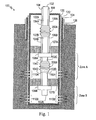
- Fig. 1 shows a simplified diagram of a production well that incorporates several expansion joints along the production tubing, in accordance with at least some illustrative embodiments
- Fig. 2A shows a detailed view of the expansion joint of Fig. 1 , in accordance with at least some illustrative embodiments;
- Fig. 2B shows the expansion joint of Fig. 1 in various states ranging from fully contracted to fully extended, in accordance with at least some illustrative embodiments;
- Fig. 3 shows a cross-sectional view of the expansion joint of Fig. 1 incorporating two hydraulic paths through the joint, in accordance with at least some illustrative embodiments;
- Fig. 4 shows a cross-sectional view of the expansion joint of Fig. 1 , incorporating both a hydraulic path and an optical fiber path through the joint, in accordance with at least some illustrative embodiments;
- Fig. 5 shows a cross-section view of the expansion joint of Fig. 1 , incorporating two hydraulic paths and a third optical fiber path through the joint, in accordance with at least some illustrative embodiments.
- Fig. 1 shows a simplified completed production well 100 using a production tubing 102 that includes tubing segments 102A, 102B, 102C, 102D and 102E, and expansion joints 200A and 200B constructed in accordance with at least some illustrative embodiments.
- the well includes surface casing 124, secured in place by cement 126, and production casing 120, concentrically located within surface casing 124 and secured in place by cement 122.
- Production tubing 102 runs the length of production well 100, from the surface through production zones A and B.
- Packers 107A and 107B are secured to both the inside of production casing 120 and the outside of production tubing 102, and serve to isolate each production zone.
- Chokes 108A and 108B operate to control the flow of product originating from the perforations within each production zone (perforations 110A within zone A, and perforations 110B within zone B, respectively) through production tubing 102.
- choke 108A is hydraulically controlled via hydraulic control line 106
- choke 108B is similarly hydraulically controlled via hydraulic control line 104.
- expansion joints 200A and 200B are inserted along the length of production tubing 102.
- Expansion joint 200A is inserted between tubing segments 102A and 102B, and operates to alleviate the stress forces that may develop along production tubing 102 and control lines 104 and 106 between the top of production casing 120 and packer 107A.
- expansion joint 200B is inserted between tubing segments 102C and 102D to alleviate the stress forces that develop along production tubing 102 and control line 104 between packer 107A and 107B.
- hydraulic fluid within hydraulic control line 104 passes through both expansion joints 200A and 200B.
- hydraulic fluid within hydraulic control line 106 passes through expansion joint 200A.
- these control lines are constructed of 1 ⁇ 4" metal tubing and are secured to the exterior of production tubing 102.
- Control line segments 104A, 104B, 106A and 106B each couple to expansion joint 200A, while control line segments 104C and 104D couple to expansion joint 200B.
- Each expansion joint shown provides a separate, isolated path for the fluid of each control line to which it is coupled, as is described in more detail below.
- Fig. 2A illustrates a detailed, cutaway view of an expansion joint 200, constructed in accordance with at least some illustrative embodiments.
- Joint 200 includes a telescoping tubular assembly that includes tubular members 213 and 215.
- Tubular member 213 has a smaller diameter than tubular member 215, is concentrically located within tubular member 215, and is able to move along the central axis of expansion joint 200.
- Tubular member 213 includes annular members 211 and 217, and annular member 217 includes apertures 209 through the annular member to permit fluid flow from one side of the annular member to the other as tubular member 213 moves within tubular member 215.
- tubular member 213 The travel of tubular member 213 is limited by annular member 217 when expansion joint 200 is fully extended and by annular member 211 when expansion joint 200 is fully contracted.
- expansion joint 200 When expansion joint 200 is either fully contracted or fully extended, the forces exerted on the expansion joint (either compressive or tensional) are transferred along tubular members 213 and 215.
- Fig. 2B illustrates expansion joint 200 while fully contracted, partially extended and fully extended.
- tubular member 215 includes annular member 210 and threaded end 216, and tubular member 213 further includes threaded collar 218 (threads not shown). Threaded end 216 and threaded collar 218 enable expansion joint 200 to be coupled to tubing segments as shown in Fig. 1 .
- Each of annular members 210 and 211 of Fig. 2A radially extend beyond the outer diameter of tubular member 215, allowing each of flexible hollow cylinders 202, 204 and 206 to be positioned outside of tubular member 215 and attached to both annular members 210 and 211.
- the flexible cylinders are implemented using bellowed walls. Such bellows may be manufactured using any of a number of techniques ( e.g. , welding together individual rings). Further, the flexible cylinders may also be implemented using structures other than bellows, and using flexible geometric shapes other than a flexible cylinder.
- the cylinders are each hermetically coupled to the annular members ( e.g. , using continuous welds around the entire circumference of the joints between the cylinder ends and the annular members).
- the resulting annular space is used to transfer fluids, such as the hydraulic fluid passing through control lines 104 and 106 of Fig. 1 .
- the transfer of fluids to these annular spaces is accomplished by including apertures within each of annular members 210 and 211 that pass through each member and are aligned with the annular spaces between the flexible cylinders.
- these apertures are extended using threaded tubing attached to the annular members (e.g. , 1 ⁇ 4" tubing similar to that used for control lines 104 and 106 of Fig. 1 ).
- Fig. 3 illustrates a cross-sectional view of the expansion joint of Fig. 1 , constructed in accordance with at least some illustrative embodiments.
- the illustrated expansion joint includes two separate fluid paths that are kept isolated from each other.
- the first path flows through aperture 214A in annular member 210, annular space 214B between flexible cylinders 202 and 204, and aperture 214C in annular member 211.
- the second path flows through aperture 212A in annular member 210, annular space 212B between flexible cylinders 204 and 206, and aperture 212C in annular member 211.
- the apertures associated with a given flow in each of the annular members are radially located on opposite sides of the cylinder to evenly distribute the fluid flow throughout the annular space.
- Other positions for, and numbers of, such apertures may also be suitable to implement the claimed expansion joint.
- At least one seal 224 is located within a groove at the end of tubular member 215 nearest to annular member 211 and around the exterior of tubular member 213 where it protrudes out from tubular member 215, as shown in Fig. 3 (as well as Figs 4 and 5 ). Such a seal operates to contain the fluid passing through the expansion joint to the interior of tubular members 213 and 215, and prevents the loss of pressure and fluid as the expansion joint extends and contracts.
- FIG. 4 illustrates a cross-sectional view of an expansion joint that allows both hydraulic fluid and an optical fiber to be routed through the same joint, in accordance with at least some illustrative embodiments.
- hydraulic fluid in the example of Fig. 4 is routed through apertures 212A and 212C, as well as annular space 212B.
- an optical fiber 214D is routed through aperture 214A, annular space 214B and aperture 214C in the example of Fig. 4 , rather than hydraulic fluid.
- Optical fiber 214D is coiled within annular space 214B so as to allow the fiber to adjust to the changes in the length of the expansion joint without substantially stressing the fiber with tensional forces as the joint extends, and to avoid exceeding the bend radius of the fiber as the joint contracts.
- optical fiber 214D is routed outside the expansion joint within a protective tubing (e.g. , 1 ⁇ 4" tubing similar to that used for control lines 104 and 106 of Fig. 1 , but not shown in Fig. 4 ) which runs along the outside of production tubing 102 as shown in Fig. 1 and protects the optical fiber from the extreme conditions present in the downhole environment
- spacers are positioned between the cylinder walls within the annular space to prevent the walls from crushing a communication medium routed through the annular space.
- spacers 222 are attached to the inside of flexible cylinder 202 such that as the expansion joint contracts, and portions of the bellowed wall of cylinder 202 move closer to portions of the bellowed wall of cylinder 204, the walls are kept at a minimum distance ( i.e. , approximately the thickness of spacer 222, accounting for some possible compression of the spacer), which protects the fiber from either being crushed or flexed beyond its bend radius. While small rectangular spacers are shown in Fig.
- any number of spacers of different sizes and shapes may be suitable for use in at least some illustrative embodiments.
- Such spacers may also be used within an annular space used to route a fluid (e.g. , annular space 212B) so as to further limit changes in the overall volume of the annular space as the expansion joint extends and contracts.
- Fig. 4 shows two annular spaces, one routing a hydraulic fluid and the other routing an optical fiber
- any number of annular spaces (limited only by the physical space limitations imposed by the dimensions of a given expansion joint)
- any number and combination of different types of communication media may be suitable for use in at least some illustrative embodiments.
- Such communication media include, but are not limited to, fluids, optical media, electrical conductors, radio frequency waveguides, acoustical media, and ultrasonic media, just to name a few examples.
- Optical fiber 216D provides a third communication medium and is routed through the expansion joint via aperture 216A, annular space 216B (between the innermost flexible cylinder and the telescoping tubular assembly) and aperture 214C.
- optical fiber 216D of Fig. 5 is coiled within annular space 216B so as to allow the fiber to adjust to the changes in the length of the expansion joint without substantially stressing the fiber with tensional forces as the joint extends, and to avoid exceeding the bend radius of the fiber as the joint contracts.
- optical fiber 214D is routed outside the expansion joint within a protective tubing (e.g. , 1 ⁇ 4" tubing similar to that used for control lines 104 and 106 of Fig. 1 , but not shown in Fig. 5 ) which runs along the outside of production tubing 102 as shown in Fig. 1 .
- a protective tubing e.g. , 1 ⁇ 4" tubing similar to that used for control lines 104 and 106 of Fig. 1 , but not shown in Fig. 5
- At least some illustrative embodiments include any of a number of pressure equalization apertures through either or both annular rings 210 and 211 to allow fluid flow between the exterior of the expansion joint and the interior of the innermost cylinder (but external to the tubing). These are shown as apertures 220 in Figs. 3 , 4 and 5 . While shown as straight, cylindrical apertures, various other shapes and routings may also be suitable to form the apertures. Also, while four such apertures are shown relatively positioned at opposite sides of annular rings 210 and 211 in Figs. 3 and 4 (and two apertures in Fig. 5 ), any number of apertures in any of a variety of relative positions may be suitable implementations of the apertures 220.
- the communication media may be used for any type of information exchange between any type of equipment, in any direction, both inside and outside the well. Further, such exchanged information may be used for controlling downhole equipment from the surface, for reporting status and/or data from downhole equipment to the surface, or for exchanging information between multiple pieces of downhole equipment located at different points along the length of the well. It is intended that the following claims be interpreted to include all such variations and modifications.
Landscapes
- Engineering & Computer Science (AREA)
- Geology (AREA)
- Life Sciences & Earth Sciences (AREA)
- Mining & Mineral Resources (AREA)
- Mechanical Engineering (AREA)
- Physics & Mathematics (AREA)
- Environmental & Geological Engineering (AREA)
- Fluid Mechanics (AREA)
- General Life Sciences & Earth Sciences (AREA)
- Geochemistry & Mineralogy (AREA)
- General Engineering & Computer Science (AREA)
- Light Guides In General And Applications Therefor (AREA)
- Joints Allowing Movement (AREA)
- Quick-Acting Or Multi-Walled Pipe Joints (AREA)
Abstract
Description
- As the worldwide demand for oil and gas has continued to escalate, the systems used to control and monitor the production of oil and gas wells have continued to increase in sophistication and complexity. It is not uncommon for wells to have a significant number of production zones, and to incorporate multiple sets of monitoring and control systems, each requiring separate sets of communication and control lines between the surface and the downhole equipment located within each production zone. Such communication and control lines may include hydraulic lines, copper electrical lines, and optical fiber lines, just to name a few examples. While techniques do exist for attaching multiple lines to production tubing as they are introduced into the well during the well completion process, the use of expansion joints along the length of the production tubing may limit or even preclude the use of multiple lines.
- Expansion joints are necessary in extreme environments that subject the production tubing to significant expansion and compression forces such as those found, for example, in offshore wells or in deep wells where the production tubing can be subjected to large variations in temperature both in the surrounding strata and in the product being extracted through the tubing. These temperature variations over very large lengths of production tubing can produce significant variations in tubing length, thus necessitating the use of expansion joints over the length of the production tubing to relieve the stresses created and to avoid damaging the tubing and any production equipment coupled to the tubing.
- Existing systems using a single control/communication line, such as a ¼" hydraulic control line attached to the outside of the production tubing from the surface to the downhole equipment being controlled (e.g., a downhole safety valve), are sometimes configured to account for the variations in tubing length at the expansion joint by coiling the control line around the joint, thus allowing the line to coil and uncoil as the joint correspondingly contracts and extends. While it is possible to incorporate such line coils around expansion joints when using a single control/communication line, such coiling may not work with systems that require even as few as two or three lines. This is due to the fact that over time, as the joint contracts and extends, the control/communication lines will tend to become entangled, which over time can damage the lines. If the lines are damaged, it may become necessary to shut the well down and set up a "workover" rig to remove the production tubing and replace the damaged lines. Such repairs are extremely expensive, both in terms of the direct costs of performing the repairs, as well as in terms of lost production due to the significant amount of time it takes to perform the repairs.
- An expansion joint with one or more communication medium bypass paths is described herein. At least some illustrative embodiments include a first axially flexible cylinder, one or more additional axially flexible cylinders positioned within the first cylinder, a first annular member positioned at a first end of, and coupled to, the first cylinder and the one or more additional cylinders (the first annular member including one or more apertures through said member), and a second annular member positioned at a second opposite end of, and coupled to, the first cylinder and the one or more additional cylinders (the second annular member including one or more apertures through said member). All cylinders concurrently extend and contract in axial length when the first and second annular members are respectively moved away from and towards each other. Annular spaces formed by each of the one or more additional cylinders and an externally adjacent cylinder, together with corresponding apertures of each of the first and second annular members, each provides at least one path for at least one communication medium.
- At least some other illustrative embodiments include a downhole production tubing system that includes a plurality of tubing segments coupled to each other to provide at least part of a path between one or more production zones within a well and the surface above the well, and an expansion joint that couples at least two of the plurality of tubing segments together. The expansion joint includes a first axially flexible cylinder, one or more additional axially flexible cylinders located within the first cylinder, a first annular member positioned at a first end of, and coupled to, the first cylinder and the one or more additional cylinders (the first annular member including one or more apertures through said member), and a second annular member positioned at a second opposite end of, and coupled to, the first cylinder and the one or more additional cylinders (the second annular member including one or more apertures through said member). All cylinders concurrently extend and contract in axial length when the first and second annular members respectively move away from and towards each other in response to expansions and contractions of at least one of the tubing segments. Annular spaces formed by each of the one or more additional cylinders and an externally adjacent cylinder, together with corresponding apertures of each of the first and second annular members, each provides at least one path for at least one communication medium used for communication between surface equipment and downhole equipment.
- Other illustrative embodiments of an expansion joint include means for flexibly encapsulating at least one communication medium (the means for encapsulating extending and contracting in a longitudinal direction) and means for securing each of two ends of the means for encapsulating (each end opposed to the other along the longitudinal direction, and each means for securing including at least one means for traversing the corresponding means for securing). Each of the means for securing moves away and towards each other as the means for encapsulating respectively extends and contracts. The means for encapsulating, in conjunction with the at least one means for traversing of each of the means for securing, provides a path through the expansion joint for the at least one communication medium.
- Still other illustrative embodiments of a downhole production tubing system include a plurality of tubing segments coupled to each other to provide at least part of a path between one or more production zones within a well and the surface above the well, and an expansion joint that couples at least two of the plurality of tubing segments together. The expansion joint includes means for flexibly encapsulating at least one communication medium (the means for encapsulating extending and contracting in a longitudinal direction), and means for securing each of two ends of the means for encapsulating (each end opposed to the other along the longitudinal direction, and each means for securing including at least one means for traversing the corresponding means for securing). Each of the means for securing moves away and towards each other as the means for encapsulating respectively extends and contracts in response to expansions and contractions of at least one of the tubing segments. The means for encapsulating, in conjunction with the at least one means for traversing of each of the means for securing, provides a path through the expansion joint for the at least one communication medium used for communication between surface equipment and downhole equipment.
- For a detailed description of at least some illustrative embodiments, reference will now be made to the accompanying drawings in which:
-
Fig. 1 shows a simplified diagram of a production well that incorporates several expansion joints along the production tubing, in accordance with at least some illustrative embodiments; -
Fig. 2A shows a detailed view of the expansion joint ofFig. 1 , in accordance with at least some illustrative embodiments; -
Fig. 2B shows the expansion joint ofFig. 1 in various states ranging from fully contracted to fully extended, in accordance with at least some illustrative embodiments; -
Fig. 3 shows a cross-sectional view of the expansion joint ofFig. 1 incorporating two hydraulic paths through the joint, in accordance with at least some illustrative embodiments; -
Fig. 4 shows a cross-sectional view of the expansion joint ofFig. 1 , incorporating both a hydraulic path and an optical fiber path through the joint, in accordance with at least some illustrative embodiments; and -
Fig. 5 shows a cross-section view of the expansion joint ofFig. 1 , incorporating two hydraulic paths and a third optical fiber path through the joint, in accordance with at least some illustrative embodiments. -
Fig. 1 shows a simplified completed production well 100 using aproduction tubing 102 that includestubing segments expansion joints surface casing 124, secured in place bycement 126, andproduction casing 120, concentrically located withinsurface casing 124 and secured in place bycement 122.Production tubing 102 runs the length of production well 100, from the surface through production zones A and B. Packers 107A and 107B are secured to both the inside ofproduction casing 120 and the outside ofproduction tubing 102, and serve to isolate each production zone.Chokes perforations 110A within zone A, andperforations 110B within zone B, respectively) throughproduction tubing 102. In the example ofFig. 1 ,choke 108A is hydraulically controlled viahydraulic control line 106, andchoke 108B is similarly hydraulically controlled viahydraulic control line 104. - Because
production tubing 102 is secured at the top ofproduction casing 120 and at each ofpackers expansion joints production tubing 102.Expansion joint 200A is inserted betweentubing segments production tubing 102 andcontrol lines production casing 120 andpacker 107A. Similarly,expansion joint 200B is inserted betweentubing segments production tubing 102 andcontrol line 104 betweenpacker - As is evident from
Fig. 1 , the hydraulic fluid withinhydraulic control line 104 passes through bothexpansion joints hydraulic control line 106 passes throughexpansion joint 200A. In at least some embodiments, these control lines are constructed of ¼" metal tubing and are secured to the exterior ofproduction tubing 102.Control line segments expansion joint 200A, whilecontrol line segments expansion joint 200B. Each expansion joint shown provides a separate, isolated path for the fluid of each control line to which it is coupled, as is described in more detail below. -
Fig. 2A illustrates a detailed, cutaway view of anexpansion joint 200, constructed in accordance with at least some illustrative embodiments.Joint 200 includes a telescoping tubular assembly that includestubular members Tubular member 213 has a smaller diameter thantubular member 215, is concentrically located withintubular member 215, and is able to move along the central axis ofexpansion joint 200.Tubular member 213 includesannular members annular member 217 includesapertures 209 through the annular member to permit fluid flow from one side of the annular member to the other astubular member 213 moves withintubular member 215. The travel oftubular member 213 is limited byannular member 217 whenexpansion joint 200 is fully extended and byannular member 211 whenexpansion joint 200 is fully contracted. Whenexpansion joint 200 is either fully contracted or fully extended, the forces exerted on the expansion joint (either compressive or tensional) are transferred alongtubular members Fig. 2B illustratesexpansion joint 200 while fully contracted, partially extended and fully extended. - Continuing to refer to
Fig. 2A ,tubular member 215 includesannular member 210 and threadedend 216, andtubular member 213 further includes threaded collar 218 (threads not shown). Threadedend 216 and threadedcollar 218 enableexpansion joint 200 to be coupled to tubing segments as shown inFig. 1 . Each ofannular members Fig. 2A radially extend beyond the outer diameter oftubular member 215, allowing each of flexiblehollow cylinders tubular member 215 and attached to bothannular members Fig. 2A , the flexible cylinders are implemented using bellowed walls. Such bellows may be manufactured using any of a number of techniques (e.g., welding together individual rings). Further, the flexible cylinders may also be implemented using structures other than bellows, and using flexible geometric shapes other than a flexible cylinder. - Each pair of adjacent flexible cylinders, together with
annular members control lines Fig. 1 . The transfer of fluids to these annular spaces is accomplished by including apertures within each ofannular members Fig. 2A , these apertures (212A, 212C, 214A and 214C) are extended using threaded tubing attached to the annular members (e.g., ¼" tubing similar to that used forcontrol lines Fig. 1 ). -
Fig. 3 illustrates a cross-sectional view of the expansion joint ofFig. 1 , constructed in accordance with at least some illustrative embodiments. The illustrated expansion joint includes two separate fluid paths that are kept isolated from each other. The first path flows throughaperture 214A inannular member 210,annular space 214B betweenflexible cylinders aperture 214C inannular member 211. The second path flows throughaperture 212A inannular member 210,annular space 212B betweenflexible cylinders aperture 212C inannular member 211. In at least some illustrative embodiments, the apertures associated with a given flow in each of the annular members are radially located on opposite sides of the cylinder to evenly distribute the fluid flow throughout the annular space. Other positions for, and numbers of, such apertures may also be suitable to implement the claimed expansion joint. - As can be seen from
Figs. 2B and3 , as the expansion joint extends and contracts, the bellows of the cylinders respectively move radially inwardly and outwardly. This movement, together with the overall radial flexibility of the cylinder walls and the large volume of the annular space relative to the diameter of the control lines, allows the volume of the annular space to remain relatively constant and produces little if any pressure variations in the fluid within the control lines coupled to the expansion joint as the joint extends and contracts. Further, because such movements within the production tubing are gradual over time, any pressure variations that do occur can be compensated using a variety of known pressure control systems and methods. - Also, as the expansion joint extends and contracts, and
tubular member 213 extends beyond or contracts intotubular member 215, it is important to maintain the pressure integrity of the telescoping tubular assembly. In at least some illustrative embodiments, at least oneseal 224 is located within a groove at the end oftubular member 215 nearest toannular member 211 and around the exterior oftubular member 213 where it protrudes out fromtubular member 215, as shown inFig. 3 (as well asFigs 4 and5 ). Such a seal operates to contain the fluid passing through the expansion joint to the interior oftubular members - Although the embodiments described above illustrate the transfer of hydraulic fluid through the expansion joints, other communication media may also be routed through the expansion joint. For example,
Fig. 4 illustrates a cross-sectional view of an expansion joint that allows both hydraulic fluid and an optical fiber to be routed through the same joint, in accordance with at least some illustrative embodiments. In a manner similar to the example ofFig. 3 , hydraulic fluid in the example ofFig. 4 is routed throughapertures annular space 212B. But anoptical fiber 214D is routed throughaperture 214A,annular space 214B andaperture 214C in the example ofFig. 4 , rather than hydraulic fluid.Optical fiber 214D is coiled withinannular space 214B so as to allow the fiber to adjust to the changes in the length of the expansion joint without substantially stressing the fiber with tensional forces as the joint extends, and to avoid exceeding the bend radius of the fiber as the joint contracts. In at least some illustrative embodiments of the expansion joint ofFig. 4 optical fiber 214D is routed outside the expansion joint within a protective tubing (e.g., ¼" tubing similar to that used forcontrol lines Fig. 1 , but not shown inFig. 4 ) which runs along the outside ofproduction tubing 102 as shown inFig. 1 and protects the optical fiber from the extreme conditions present in the downhole environment - In at least some illustrative embodiments, spacers are positioned between the cylinder walls within the annular space to prevent the walls from crushing a communication medium routed through the annular space. In the example of
Fig. 4 ,spacers 222 are attached to the inside offlexible cylinder 202 such that as the expansion joint contracts, and portions of the bellowed wall ofcylinder 202 move closer to portions of the bellowed wall ofcylinder 204, the walls are kept at a minimum distance (i.e., approximately the thickness ofspacer 222, accounting for some possible compression of the spacer), which protects the fiber from either being crushed or flexed beyond its bend radius. While small rectangular spacers are shown inFig. 4 , any number of spacers of different sizes and shapes may be suitable for use in at least some illustrative embodiments. Such spacers may also be used within an annular space used to route a fluid (e.g.,annular space 212B) so as to further limit changes in the overall volume of the annular space as the expansion joint extends and contracts. - Additionally, while the example of
Fig. 4 shows two annular spaces, one routing a hydraulic fluid and the other routing an optical fiber, any number of annular spaces (limited only by the physical space limitations imposed by the dimensions of a given expansion joint), any number and combination of different types of communication media, and any type of communication media may be suitable for use in at least some illustrative embodiments. Such communication media include, but are not limited to, fluids, optical media, electrical conductors, radio frequency waveguides, acoustical media, and ultrasonic media, just to name a few examples. - In another illustrative embodiment shown in
Fig. 5 , the twoannular spaces Optical fiber 216D provides a third communication medium and is routed through the expansion joint viaaperture 216A,annular space 216B (between the innermost flexible cylinder and the telescoping tubular assembly) andaperture 214C. As in the example ofFig. 3 ,optical fiber 216D ofFig. 5 is coiled withinannular space 216B so as to allow the fiber to adjust to the changes in the length of the expansion joint without substantially stressing the fiber with tensional forces as the joint extends, and to avoid exceeding the bend radius of the fiber as the joint contracts. In a manner similar to the example ofFig. 4 , in at least some illustrative embodiments of the expansion joint ofFig. 5 optical fiber 214D is routed outside the expansion joint within a protective tubing (e.g., ¼" tubing similar to that used forcontrol lines Fig. 1 , but not shown inFig. 5 ) which runs along the outside ofproduction tubing 102 as shown inFig. 1 . - To avoid subjecting the flexible cylinder walls to additional stresses caused by pressure differences between the region external to the expansion joint and the region between the innermost flexible cylinder and the telescoping tubing, at least some illustrative embodiments include any of a number of pressure equalization apertures through either or both
annular rings apertures 220 inFigs. 3 ,4 and5 . While shown as straight, cylindrical apertures, various other shapes and routings may also be suitable to form the apertures. Also, while four such apertures are shown relatively positioned at opposite sides ofannular rings Figs. 3 and4 (and two apertures inFig. 5 ), any number of apertures in any of a variety of relative positions may be suitable implementations of theapertures 220. - The above discussion is meant to illustrate the principles and at least some embodiments. Other variations and modifications will become apparent to those of ordinary skill in the art once the above disclosure is fully appreciated. For example, while some of the embodiments describe the use of communication media to operate chokes positioned along a production tubing within a well, the communication media may be used for any type of information exchange between any type of equipment, in any direction, both inside and outside the well. Further, such exchanged information may be used for controlling downhole equipment from the surface, for reporting status and/or data from downhole equipment to the surface, or for exchanging information between multiple pieces of downhole equipment located at different points along the length of the well. It is intended that the following claims be interpreted to include all such variations and modifications.
Claims (16)
- An expansion joint, comprising:a first axially flexible cylinder;one or more additional axially flexible cylinders positioned within the first cylinder;a first annular member positioned at a first end of, and coupled to, the first cylinder and the one or more additional cylinders, the first annular member comprising one or more apertures through said member; anda second annular member positioned at a second opposite end of, and coupled to, the first cylinder and the one or more additional cylinders, the second annular member comprising one or more apertures through said member;wherein all cylinders concurrently extend and contract in axial length when the first and second annular members are respectively moved away from and towards each other; and
wherein annular spaces formed by each of the one or more additional cylinders and an externally adjacent cylinder, together with corresponding apertures of each of the first and second annular members, each provides at least one path for at least one communication medium. - The expansion joint of claim 1, wherein the first and second annular members are hermetically coupled to at least two adjacent cylinders.
- The expansion joint of claim 1 or 2, wherein the at least one communication medium comprises at least one medium selected from the group consisting of a hydraulic fluid, an electrical cable and an optical fiber.
- The expansion joint of claim 1, 2 or 3, further comprising:a telescoping tubular assembly comprising a plurality of concentric tubular members, said tubular assembly sustaining and transferring substantially all of the tensional and compressive forces exerted through the expansion joint when respectively fully extended and fully contracted;wherein an outermost tubular member of the plurality of tubular members comprises the first annular member, and an innermost tubular member of the plurality of tubular members comprises the second annular member; and
wherein the telescoping tubular assembly axially extends and contracts concurrently with all the cylinders. - The expansion joint of claim 4,
wherein the annular space between the innermost cylinder and the telescoping tubular assembly, together with at least one corresponding additional aperture through each of the first and second annular members, provides at least one additional path for at least one additional communication medium; and
wherein the at least one additional communication medium comprises at least one medium selected from the group consisting of an electrical cable and an optical fiber. - The expansion joint of claim 1, 2, 3, 4 or 5, further comprising one or more spacers positioned between facing surfaces of two adjacent cylinders, wherein the spacers maintain a minimum spacing between the two adjacent cylinders.
- The expansion joint of claim 1, 2, 3, 4, 5 or 6, further comprising one or more pressure equalization apertures that each provides a fluid flow path between a first region external to an outermost cylinder and a second region internal to an innermost cylinder.
- A downhole production tubing system, comprising:a plurality of tubing segments coupled to each other to provide at least part of a path between one or more production zones within a well and the surface above the well; andan expansion joint according to any one of claims 1 to 7, that couples at least two of the plurality of tubing segments together.
- An expansion joint, comprising:means for flexibly encapsulating at least one communication medium, the means for encapsulating extending and contracting in a longitudinal direction; andmeans for securing each of two ends of the means for encapsulating, each end opposed to the other along the longitudinal direction, and each means for securing comprising at least one means for traversing the corresponding means for securing;wherein each of the means for securing moves away and towards each other as the means for encapsulating respectively extends and contracts; and
wherein the means for encapsulating, in conjunction with the at least one means for traversing each of the means for securing, provides a path through the expansion joint for the at least one communication medium. - The expansion joint of claim 9, wherein the means for encapsulating encapsulates a plurality of communication media and comprises a means for maintaining separation of two adjacent communication media of said plurality of communication media, or wherein the means for encapsulating further individually encapsulates each of a plurality of communication media.
- The expansion joint of claim 9 or 10, wherein each of the means for securing hermetically couples to one of the two ends of the means for encapsulating, or each end of the means for encapsulating hermetically couples to a corresponding means for securing.
- The expansion joint of claim 9, 10 or 11, wherein the at least one communication medium comprises at least one medium selected from the group consisting of a hydraulic fluid, an electrical cable and an optical fiber.
- The expansion joint of claim 9, 10, 11 or 12, further comprising:means for flexibly containing and transporting a fluid, and for sustaining and transferring substantially all of the tensional and compressive forces exerted through the expansion joint when respectively fully extended and fully contracted;wherein the means for containing, transporting and transferring comprises the means for securing both ends of the means for encapsulating; and
wherein the means for containing, transporting and transferring extends and contracts in the longitudinal direction concurrently with the means for encapsulating. - The expansion joint of claim 13,
wherein the annular space between the innermost means for encapsulating and the means for containing, transporting and transferring, in conjunction with the at least one additional means for traversing each of the means for securing, provides at least one additional path through the expansion joint for at least one additional communication medium; and
wherein the at least one additional communication medium comprises at least one medium selected from the group consisting of an electrical cable and an optical fiber. - The expansion joint of claim 9, 10, 11, 12, 13 or 14, further comprising means for equalizing pressures between a first region external to an outermost surface of the means for encapsulating and a second region internal to an innermost surface of the means for encapsulating.
- A downhole production tubing system, comprising:a plurality of tubing segments coupled to each other to provide at least part of a path between one or more production zones within a well and the surface above the well; andan expansion joint according to any one of claims 9 to 15, that couples at least two of the plurality of tubing segments together,wherein each of the means for securing moves away and towards each other as the means for encapsulating respectively extends and contracts in response to expansions and contractions of at least one of the tubing segments; and
wherein the means for encapsulating, in conjunction with the at least one means for traversing each of the means for securing, provides a path through the expansion joint for the at least one communication medium used for communication between surface equipment and downhole equipment.
Applications Claiming Priority (1)
| Application Number | Priority Date | Filing Date | Title |
|---|---|---|---|
| US12/258,780 US7810560B2 (en) | 2008-10-27 | 2008-10-27 | Expansion joint with communication medium bypass |
Publications (2)
| Publication Number | Publication Date |
|---|---|
| EP2180133A1 true EP2180133A1 (en) | 2010-04-28 |
| EP2180133B1 EP2180133B1 (en) | 2012-01-25 |
Family
ID=41531657
Family Applications (1)
| Application Number | Title | Priority Date | Filing Date |
|---|---|---|---|
| EP09013341A Not-in-force EP2180133B1 (en) | 2008-10-27 | 2009-10-22 | Expansion joint with communication medium bypass |
Country Status (4)
| Country | Link |
|---|---|
| US (1) | US7810560B2 (en) |
| EP (1) | EP2180133B1 (en) |
| AT (1) | ATE542980T1 (en) |
| BR (1) | BRPI0904190B1 (en) |
Cited By (2)
| Publication number | Priority date | Publication date | Assignee | Title |
|---|---|---|---|---|
| US20110067880A1 (en) * | 2008-12-11 | 2011-03-24 | Vetco Gray Inc. | Bellows type adjustable casing |
| US8387707B2 (en) | 2008-12-11 | 2013-03-05 | Vetco Gray Inc. | Bellows type adjustable casing |
Families Citing this family (12)
| Publication number | Priority date | Publication date | Assignee | Title |
|---|---|---|---|---|
| US8875791B2 (en) * | 2010-10-18 | 2014-11-04 | Schlumberger Technology Corporation | Segmented fiber optic coiled tubing assembly |
| US8915304B2 (en) * | 2011-07-30 | 2014-12-23 | Halliburton Energy Services, Inc. | Traversing a travel joint with a fluid line |
| WO2014130032A1 (en) * | 2013-02-21 | 2014-08-28 | Halliburton Energy Services, Inc. | Method and system for directing control lines along a travel joint |
| US9664000B2 (en) | 2013-07-08 | 2017-05-30 | Halliburton Energy Services, Inc. | Continuously sealing telescoping joint having multiple control lines |
| WO2015005895A1 (en) * | 2013-07-08 | 2015-01-15 | Halliburton Energy Services, Inc. | Telescoping joint with control line management assembly |
| US9650846B2 (en) | 2013-12-09 | 2017-05-16 | Baker Hughes Incorporated | Completion systems including reduced stress expandable control lines |
| WO2015143171A1 (en) * | 2014-03-19 | 2015-09-24 | Schlumberger Canada Limited | Contraction joint with multiple telescoping sections |
| WO2015174955A1 (en) * | 2014-05-12 | 2015-11-19 | Halliburton Energy Services, Inc. | Multiple control line travel joint with injection line capability |
| US9869322B2 (en) * | 2014-05-16 | 2018-01-16 | Baker Hughes, A Ge Company, Llc | Metal bellows seal section and method to evacuate air during filling |
| AU2016423067B2 (en) * | 2016-09-14 | 2021-12-02 | Halliburton Energy Services, Inc. | Travel joint |
| EP3731610B1 (en) * | 2019-04-23 | 2023-11-15 | ABB Schweiz AG | Heat exchanging arrangement and subsea electronic system |
| WO2021251976A1 (en) | 2020-06-11 | 2021-12-16 | Halliburton Energy Services, Inc. | A multi-flow compaction/expansion joint |
Citations (6)
| Publication number | Priority date | Publication date | Assignee | Title |
|---|---|---|---|---|
| US4576404A (en) * | 1983-08-04 | 1986-03-18 | Exxon Research And Engineering Co. | Bellows expansion joint |
| US20030221829A1 (en) * | 2000-12-07 | 2003-12-04 | Patel Dinesh R. | Well communication system |
| GB2415834A (en) * | 2004-07-01 | 2006-01-04 | Schlumberger Holdings | Downhole cable slack compensator |
| US20070074872A1 (en) * | 2005-09-30 | 2007-04-05 | Schlumberger Technology Corporation | Apparatus, Pumping System Incorporating Same, and Methods of Protecting Pump Components |
| US20090032268A1 (en) * | 2007-08-01 | 2009-02-05 | Blanton James R | Installation of lines in well tools |
| US20090078430A1 (en) * | 2007-09-24 | 2009-03-26 | Schlumberger Technology Corporation | Contraction joint system |
Family Cites Families (12)
| Publication number | Priority date | Publication date | Assignee | Title |
|---|---|---|---|---|
| US916136A (en) * | 1908-05-23 | 1909-03-23 | Thomas Burton Ford | High-pressure hose. |
| US3747961A (en) * | 1971-05-05 | 1973-07-24 | Ric Wil Inc | Conduit system |
| US3884512A (en) * | 1971-05-26 | 1975-05-20 | Mancar Trust | Deep-well drilling arrangement |
| US4278277A (en) * | 1979-07-26 | 1981-07-14 | Pieter Krijgsman | Structure for compensating for different thermal expansions of inner and outer concentrically mounted pipes |
| US4385668A (en) * | 1981-02-25 | 1983-05-31 | Turbo Resources Ltd. | Inner pipe support arrangement for double-walled drill pipe |
| US4445332A (en) * | 1982-03-24 | 1984-05-01 | Caterpillar Tractor Co. | Hydraulic hose assembly and method |
| US4984827A (en) * | 1987-01-30 | 1991-01-15 | Lockheed Corporation | Concentric piping flex joint |
| US5054523A (en) * | 1990-03-23 | 1991-10-08 | Unidynamics Corporation | Containment system for flexible underground piping |
| US5226495A (en) * | 1992-05-18 | 1993-07-13 | Mobil Oil Corporation | Fines control in deviated wells |
| US5351727A (en) * | 1994-01-18 | 1994-10-04 | Dayco Products Inc. | Fuel dispensing system, hose assembly therefor and methods of making the same |
| US6634676B1 (en) * | 2002-03-13 | 2003-10-21 | Abell Corporation | Rotomolded containment fitting and method of use |
| US7445248B2 (en) * | 2006-01-06 | 2008-11-04 | Caterpillar Inc. | Thermal expansion joint |
-
2008
- 2008-10-27 US US12/258,780 patent/US7810560B2/en not_active Expired - Fee Related
-
2009
- 2009-10-22 AT AT09013341T patent/ATE542980T1/en active
- 2009-10-22 EP EP09013341A patent/EP2180133B1/en not_active Not-in-force
- 2009-10-23 BR BRPI0904190-7A patent/BRPI0904190B1/en not_active IP Right Cessation
Patent Citations (6)
| Publication number | Priority date | Publication date | Assignee | Title |
|---|---|---|---|---|
| US4576404A (en) * | 1983-08-04 | 1986-03-18 | Exxon Research And Engineering Co. | Bellows expansion joint |
| US20030221829A1 (en) * | 2000-12-07 | 2003-12-04 | Patel Dinesh R. | Well communication system |
| GB2415834A (en) * | 2004-07-01 | 2006-01-04 | Schlumberger Holdings | Downhole cable slack compensator |
| US20070074872A1 (en) * | 2005-09-30 | 2007-04-05 | Schlumberger Technology Corporation | Apparatus, Pumping System Incorporating Same, and Methods of Protecting Pump Components |
| US20090032268A1 (en) * | 2007-08-01 | 2009-02-05 | Blanton James R | Installation of lines in well tools |
| US20090078430A1 (en) * | 2007-09-24 | 2009-03-26 | Schlumberger Technology Corporation | Contraction joint system |
Cited By (8)
| Publication number | Priority date | Publication date | Assignee | Title |
|---|---|---|---|---|
| US20110067880A1 (en) * | 2008-12-11 | 2011-03-24 | Vetco Gray Inc. | Bellows type adjustable casing |
| US8387707B2 (en) | 2008-12-11 | 2013-03-05 | Vetco Gray Inc. | Bellows type adjustable casing |
| US8783362B2 (en) * | 2008-12-11 | 2014-07-22 | Vetco Gray Inc. | Bellows type adjustable casing |
| GB2486054A (en) * | 2010-11-30 | 2012-06-06 | Vetco Gray Inc | Axially extendable/compressible casing segment |
| CN102536135A (en) * | 2010-11-30 | 2012-07-04 | 韦特柯格雷公司 | Bellows type adjustable casing |
| CN102536135B (en) * | 2010-11-30 | 2016-03-16 | 韦特柯格雷公司 | Bellows type adjustable casing |
| GB2486054B (en) * | 2010-11-30 | 2018-02-21 | Vetco Gray Inc | Bellows type adjustable casing |
| NO343641B1 (en) * | 2010-11-30 | 2019-04-15 | Vetco Gray Inc | Submarine device for conveying fluids from a subsea wellbore |
Also Published As
| Publication number | Publication date |
|---|---|
| US7810560B2 (en) | 2010-10-12 |
| EP2180133B1 (en) | 2012-01-25 |
| ATE542980T1 (en) | 2012-02-15 |
| US20100101778A1 (en) | 2010-04-29 |
| BRPI0904190B1 (en) | 2019-03-06 |
| BRPI0904190A2 (en) | 2010-11-09 |
Similar Documents
| Publication | Publication Date | Title |
|---|---|---|
| EP2180133B1 (en) | Expansion joint with communication medium bypass | |
| US11078730B2 (en) | Pressure equalization apparatus and associated systems and methods | |
| US10767463B2 (en) | Downhole distributed pressure sensor arrays, pressure sensors, downhole distributed pressure sensor arrays including quartz resonator sensors, and related methods | |
| EP2959097B1 (en) | Method and system for directing control lines along a travel joint | |
| US20100139909A1 (en) | Intelligent Well Control System for Three or More Zones | |
| EP0811109A4 (en) | METAL SPIRAL TUBING PROVIDED WITH A PASSAGE FOR SIGNAL TRANSMISSION | |
| US10018033B2 (en) | Downhole distributed sensor arrays for measuring at least one of pressure and temperature, downhole distributed sensor arrays including at least one weld joint, and methods of forming sensors arrays for downhole use including welding | |
| US9027639B2 (en) | Sand control screen assembly with internal control lines | |
| CN103703212A (en) | Pipe-in-pipe apparatus, and methods and systems | |
| US9000296B2 (en) | Electronics frame with shape memory seal elements | |
| KR20100094507A (en) | A spiral heat exchanger | |
| US20250059848A1 (en) | System and methodology for bypassing through an expandable metal packer | |
| JP7478838B2 (en) | Tightly controlled axial clearance assembly for insulation of threaded connectors on vacuum insulated pipes | |
| US4635968A (en) | Method and apparatus for protecting consecutive multiple variable diameter couplings | |
| CA2938131C (en) | Fluid pipe assembly including length compensator and related methods | |
| CN218626911U (en) | Flexible connection section of high-temperature flue gas exhaust system | |
| US20200362660A1 (en) | System and methodology for providing bypass through a swellable packer | |
| CN120187932A (en) | Temperature compensator for improved sealing | |
| WO2025037168A1 (en) | Well pipe having electrical conductor with improved electrical contacts | |
| SU941543A1 (en) | Versions of apparatus for casing-in a well | |
| KR20260027228A (en) | Pressure compensation system with double barrier | |
| OA20911A (en) | Assembly with tightly controlled axial gap for threaded connector insulation on vacuum insulated tubing. | |
| US20200331188A1 (en) | Long flexible tubing element (variants) | |
| CA3116722A1 (en) | Harness for intelligent completions |
Legal Events
| Date | Code | Title | Description |
|---|---|---|---|
| PUAI | Public reference made under article 153(3) epc to a published international application that has entered the european phase |
Free format text: ORIGINAL CODE: 0009012 |
|
| 17P | Request for examination filed |
Effective date: 20091116 |
|
| AK | Designated contracting states |
Kind code of ref document: A1 Designated state(s): AT BE BG CH CY CZ DE DK EE ES FI FR GB GR HR HU IE IS IT LI LT LU LV MC MK MT NL NO PL PT RO SE SI SK SM TR |
|
| AX | Request for extension of the european patent |
Extension state: AL BA RS |
|
| RIC1 | Information provided on ipc code assigned before grant |
Ipc: F16L 51/02 20060101ALI20110513BHEP Ipc: E21B 17/07 20060101ALI20110513BHEP Ipc: E21B 17/02 20060101AFI20110513BHEP |
|
| GRAP | Despatch of communication of intention to grant a patent |
Free format text: ORIGINAL CODE: EPIDOSNIGR1 |
|
| GRAS | Grant fee paid |
Free format text: ORIGINAL CODE: EPIDOSNIGR3 |
|
| GRAA | (expected) grant |
Free format text: ORIGINAL CODE: 0009210 |
|
| AK | Designated contracting states |
Kind code of ref document: B1 Designated state(s): AT BE BG CH CY CZ DE DK EE ES FI FR GB GR HR HU IE IS IT LI LT LU LV MC MK MT NL NO PL PT RO SE SI SK SM TR |
|
| REG | Reference to a national code |
Ref country code: GB Ref legal event code: FG4D |
|
| REG | Reference to a national code |
Ref country code: CH Ref legal event code: EP |
|
| REG | Reference to a national code |
Ref country code: AT Ref legal event code: REF Ref document number: 542980 Country of ref document: AT Kind code of ref document: T Effective date: 20120215 |
|
| REG | Reference to a national code |
Ref country code: IE Ref legal event code: FG4D |
|
| REG | Reference to a national code |
Ref country code: DE Ref legal event code: R096 Ref document number: 602009004848 Country of ref document: DE Effective date: 20120322 |
|
| REG | Reference to a national code |
Ref country code: NO Ref legal event code: T2 Effective date: 20120125 |
|
| REG | Reference to a national code |
Ref country code: NL Ref legal event code: VDEP Effective date: 20120125 |
|
| LTIE | Lt: invalidation of european patent or patent extension |
Effective date: 20120125 |
|
| PG25 | Lapsed in a contracting state [announced via postgrant information from national office to epo] |
Ref country code: BE Free format text: LAPSE BECAUSE OF FAILURE TO SUBMIT A TRANSLATION OF THE DESCRIPTION OR TO PAY THE FEE WITHIN THE PRESCRIBED TIME-LIMIT Effective date: 20120125 Ref country code: IS Free format text: LAPSE BECAUSE OF FAILURE TO SUBMIT A TRANSLATION OF THE DESCRIPTION OR TO PAY THE FEE WITHIN THE PRESCRIBED TIME-LIMIT Effective date: 20120525 Ref country code: HR Free format text: LAPSE BECAUSE OF FAILURE TO SUBMIT A TRANSLATION OF THE DESCRIPTION OR TO PAY THE FEE WITHIN THE PRESCRIBED TIME-LIMIT Effective date: 20120125 Ref country code: BG Free format text: LAPSE BECAUSE OF FAILURE TO SUBMIT A TRANSLATION OF THE DESCRIPTION OR TO PAY THE FEE WITHIN THE PRESCRIBED TIME-LIMIT Effective date: 20120425 Ref country code: NL Free format text: LAPSE BECAUSE OF FAILURE TO SUBMIT A TRANSLATION OF THE DESCRIPTION OR TO PAY THE FEE WITHIN THE PRESCRIBED TIME-LIMIT Effective date: 20120125 Ref country code: LT Free format text: LAPSE BECAUSE OF FAILURE TO SUBMIT A TRANSLATION OF THE DESCRIPTION OR TO PAY THE FEE WITHIN THE PRESCRIBED TIME-LIMIT Effective date: 20120125 |
|
| PG25 | Lapsed in a contracting state [announced via postgrant information from national office to epo] |
Ref country code: PT Free format text: LAPSE BECAUSE OF FAILURE TO SUBMIT A TRANSLATION OF THE DESCRIPTION OR TO PAY THE FEE WITHIN THE PRESCRIBED TIME-LIMIT Effective date: 20120525 Ref country code: PL Free format text: LAPSE BECAUSE OF FAILURE TO SUBMIT A TRANSLATION OF THE DESCRIPTION OR TO PAY THE FEE WITHIN THE PRESCRIBED TIME-LIMIT Effective date: 20120125 Ref country code: FI Free format text: LAPSE BECAUSE OF FAILURE TO SUBMIT A TRANSLATION OF THE DESCRIPTION OR TO PAY THE FEE WITHIN THE PRESCRIBED TIME-LIMIT Effective date: 20120125 Ref country code: GR Free format text: LAPSE BECAUSE OF FAILURE TO SUBMIT A TRANSLATION OF THE DESCRIPTION OR TO PAY THE FEE WITHIN THE PRESCRIBED TIME-LIMIT Effective date: 20120426 Ref country code: LV Free format text: LAPSE BECAUSE OF FAILURE TO SUBMIT A TRANSLATION OF THE DESCRIPTION OR TO PAY THE FEE WITHIN THE PRESCRIBED TIME-LIMIT Effective date: 20120125 |
|
| REG | Reference to a national code |
Ref country code: AT Ref legal event code: MK05 Ref document number: 542980 Country of ref document: AT Kind code of ref document: T Effective date: 20120125 |
|
| PG25 | Lapsed in a contracting state [announced via postgrant information from national office to epo] |
Ref country code: CY Free format text: LAPSE BECAUSE OF FAILURE TO SUBMIT A TRANSLATION OF THE DESCRIPTION OR TO PAY THE FEE WITHIN THE PRESCRIBED TIME-LIMIT Effective date: 20120125 |
|
| PG25 | Lapsed in a contracting state [announced via postgrant information from national office to epo] |
Ref country code: SE Free format text: LAPSE BECAUSE OF FAILURE TO SUBMIT A TRANSLATION OF THE DESCRIPTION OR TO PAY THE FEE WITHIN THE PRESCRIBED TIME-LIMIT Effective date: 20120125 Ref country code: EE Free format text: LAPSE BECAUSE OF FAILURE TO SUBMIT A TRANSLATION OF THE DESCRIPTION OR TO PAY THE FEE WITHIN THE PRESCRIBED TIME-LIMIT Effective date: 20120125 Ref country code: RO Free format text: LAPSE BECAUSE OF FAILURE TO SUBMIT A TRANSLATION OF THE DESCRIPTION OR TO PAY THE FEE WITHIN THE PRESCRIBED TIME-LIMIT Effective date: 20120125 Ref country code: CZ Free format text: LAPSE BECAUSE OF FAILURE TO SUBMIT A TRANSLATION OF THE DESCRIPTION OR TO PAY THE FEE WITHIN THE PRESCRIBED TIME-LIMIT Effective date: 20120125 Ref country code: DK Free format text: LAPSE BECAUSE OF FAILURE TO SUBMIT A TRANSLATION OF THE DESCRIPTION OR TO PAY THE FEE WITHIN THE PRESCRIBED TIME-LIMIT Effective date: 20120125 Ref country code: SI Free format text: LAPSE BECAUSE OF FAILURE TO SUBMIT A TRANSLATION OF THE DESCRIPTION OR TO PAY THE FEE WITHIN THE PRESCRIBED TIME-LIMIT Effective date: 20120125 |
|
| PG25 | Lapsed in a contracting state [announced via postgrant information from national office to epo] |
Ref country code: IT Free format text: LAPSE BECAUSE OF FAILURE TO SUBMIT A TRANSLATION OF THE DESCRIPTION OR TO PAY THE FEE WITHIN THE PRESCRIBED TIME-LIMIT Effective date: 20120125 Ref country code: SK Free format text: LAPSE BECAUSE OF FAILURE TO SUBMIT A TRANSLATION OF THE DESCRIPTION OR TO PAY THE FEE WITHIN THE PRESCRIBED TIME-LIMIT Effective date: 20120125 |
|
| PLBE | No opposition filed within time limit |
Free format text: ORIGINAL CODE: 0009261 |
|
| STAA | Information on the status of an ep patent application or granted ep patent |
Free format text: STATUS: NO OPPOSITION FILED WITHIN TIME LIMIT |
|
| 26N | No opposition filed |
Effective date: 20121026 |
|
| PG25 | Lapsed in a contracting state [announced via postgrant information from national office to epo] |
Ref country code: AT Free format text: LAPSE BECAUSE OF FAILURE TO SUBMIT A TRANSLATION OF THE DESCRIPTION OR TO PAY THE FEE WITHIN THE PRESCRIBED TIME-LIMIT Effective date: 20120125 |
|
| REG | Reference to a national code |
Ref country code: DE Ref legal event code: R097 Ref document number: 602009004848 Country of ref document: DE Effective date: 20121026 |
|
| PG25 | Lapsed in a contracting state [announced via postgrant information from national office to epo] |
Ref country code: ES Free format text: LAPSE BECAUSE OF FAILURE TO SUBMIT A TRANSLATION OF THE DESCRIPTION OR TO PAY THE FEE WITHIN THE PRESCRIBED TIME-LIMIT Effective date: 20120506 |
|
| PG25 | Lapsed in a contracting state [announced via postgrant information from national office to epo] |
Ref country code: MC Free format text: LAPSE BECAUSE OF NON-PAYMENT OF DUE FEES Effective date: 20121031 |
|
| REG | Reference to a national code |
Ref country code: IE Ref legal event code: MM4A |
|
| REG | Reference to a national code |
Ref country code: FR Ref legal event code: ST Effective date: 20130628 |
|
| PG25 | Lapsed in a contracting state [announced via postgrant information from national office to epo] |
Ref country code: DE Free format text: LAPSE BECAUSE OF NON-PAYMENT OF DUE FEES Effective date: 20130501 Ref country code: IE Free format text: LAPSE BECAUSE OF NON-PAYMENT OF DUE FEES Effective date: 20121022 |
|
| REG | Reference to a national code |
Ref country code: DE Ref legal event code: R119 Ref document number: 602009004848 Country of ref document: DE Effective date: 20130501 |
|
| PG25 | Lapsed in a contracting state [announced via postgrant information from national office to epo] |
Ref country code: FR Free format text: LAPSE BECAUSE OF NON-PAYMENT OF DUE FEES Effective date: 20121031 |
|
| PG25 | Lapsed in a contracting state [announced via postgrant information from national office to epo] |
Ref country code: MT Free format text: LAPSE BECAUSE OF FAILURE TO SUBMIT A TRANSLATION OF THE DESCRIPTION OR TO PAY THE FEE WITHIN THE PRESCRIBED TIME-LIMIT Effective date: 20120125 |
|
| PG25 | Lapsed in a contracting state [announced via postgrant information from national office to epo] |
Ref country code: TR Free format text: LAPSE BECAUSE OF FAILURE TO SUBMIT A TRANSLATION OF THE DESCRIPTION OR TO PAY THE FEE WITHIN THE PRESCRIBED TIME-LIMIT Effective date: 20120125 |
|
| PG25 | Lapsed in a contracting state [announced via postgrant information from national office to epo] |
Ref country code: SM Free format text: LAPSE BECAUSE OF FAILURE TO SUBMIT A TRANSLATION OF THE DESCRIPTION OR TO PAY THE FEE WITHIN THE PRESCRIBED TIME-LIMIT Effective date: 20120125 Ref country code: LU Free format text: LAPSE BECAUSE OF NON-PAYMENT OF DUE FEES Effective date: 20121022 |
|
| REG | Reference to a national code |
Ref country code: CH Ref legal event code: PL |
|
| PG25 | Lapsed in a contracting state [announced via postgrant information from national office to epo] |
Ref country code: CH Free format text: LAPSE BECAUSE OF NON-PAYMENT OF DUE FEES Effective date: 20131031 Ref country code: HU Free format text: LAPSE BECAUSE OF FAILURE TO SUBMIT A TRANSLATION OF THE DESCRIPTION OR TO PAY THE FEE WITHIN THE PRESCRIBED TIME-LIMIT Effective date: 20091022 Ref country code: LI Free format text: LAPSE BECAUSE OF NON-PAYMENT OF DUE FEES Effective date: 20131031 |
|
| PG25 | Lapsed in a contracting state [announced via postgrant information from national office to epo] |
Ref country code: MK Free format text: LAPSE BECAUSE OF FAILURE TO SUBMIT A TRANSLATION OF THE DESCRIPTION OR TO PAY THE FEE WITHIN THE PRESCRIBED TIME-LIMIT Effective date: 20120125 |
|
| REG | Reference to a national code |
Ref country code: GB Ref legal event code: 732E Free format text: REGISTERED BETWEEN 20151029 AND 20151104 |
|
| REG | Reference to a national code |
Ref country code: NO Ref legal event code: CHAD Owner name: WEATHERFORD TECHNOLOGY HOLDINGS, US Ref country code: NO Ref legal event code: CREP Representative=s name: BRYN AARFLOT AS, STORTINGSGATA 8, 0161 OSLO, NORGE |
|
| REG | Reference to a national code |
Ref country code: NO Ref legal event code: PLED Effective date: 20200525 |
|
| REG | Reference to a national code |
Ref country code: GB Ref legal event code: 732E Free format text: REGISTERED BETWEEN 20200813 AND 20200819 |
|
| REG | Reference to a national code |
Ref country code: GB Ref legal event code: 732E Free format text: REGISTERED BETWEEN 20201126 AND 20201202 |
|
| PGFP | Annual fee paid to national office [announced via postgrant information from national office to epo] |
Ref country code: NO Payment date: 20201012 Year of fee payment: 12 Ref country code: GB Payment date: 20201001 Year of fee payment: 12 |
|
| REG | Reference to a national code |
Ref country code: GB Ref legal event code: 732E Free format text: REGISTERED BETWEEN 20210225 AND 20210303 |
|
| REG | Reference to a national code |
Ref country code: NO Ref legal event code: MMEP |
|
| GBPC | Gb: european patent ceased through non-payment of renewal fee |
Effective date: 20211022 |
|
| PG25 | Lapsed in a contracting state [announced via postgrant information from national office to epo] |
Ref country code: NO Free format text: LAPSE BECAUSE OF NON-PAYMENT OF DUE FEES Effective date: 20211031 Ref country code: GB Free format text: LAPSE BECAUSE OF NON-PAYMENT OF DUE FEES Effective date: 20211022 |