EP2179946A1 - Container conveyance apparatus - Google Patents
Container conveyance apparatus Download PDFInfo
- Publication number
- EP2179946A1 EP2179946A1 EP08740738A EP08740738A EP2179946A1 EP 2179946 A1 EP2179946 A1 EP 2179946A1 EP 08740738 A EP08740738 A EP 08740738A EP 08740738 A EP08740738 A EP 08740738A EP 2179946 A1 EP2179946 A1 EP 2179946A1
- Authority
- EP
- European Patent Office
- Prior art keywords
- container
- conveyer
- containers
- passage
- over
- Prior art date
- Legal status (The legal status is an assumption and is not a legal conclusion. Google has not performed a legal analysis and makes no representation as to the accuracy of the status listed.)
- Withdrawn
Links
- 238000007599 discharging Methods 0.000 claims description 5
- 238000000576 coating method Methods 0.000 claims description 3
- 239000011248 coating agent Substances 0.000 claims description 2
- 238000007740 vapor deposition Methods 0.000 description 53
- 238000009434 installation Methods 0.000 description 5
- 238000011144 upstream manufacturing Methods 0.000 description 5
- 230000003247 decreasing effect Effects 0.000 description 2
- 230000000694 effects Effects 0.000 description 1
- 238000004519 manufacturing process Methods 0.000 description 1
- 230000002093 peripheral effect Effects 0.000 description 1
- 239000007858 starting material Substances 0.000 description 1
Images





Classifications
-
- B—PERFORMING OPERATIONS; TRANSPORTING
- B65—CONVEYING; PACKING; STORING; HANDLING THIN OR FILAMENTARY MATERIAL
- B65G—TRANSPORT OR STORAGE DEVICES, e.g. CONVEYORS FOR LOADING OR TIPPING, SHOP CONVEYOR SYSTEMS OR PNEUMATIC TUBE CONVEYORS
- B65G47/00—Article or material-handling devices associated with conveyors; Methods employing such devices
- B65G47/74—Feeding, transfer, or discharging devices of particular kinds or types
- B65G47/84—Star-shaped wheels or devices having endless travelling belts or chains, the wheels or devices being equipped with article-engaging elements
-
- B—PERFORMING OPERATIONS; TRANSPORTING
- B65—CONVEYING; PACKING; STORING; HANDLING THIN OR FILAMENTARY MATERIAL
- B65G—TRANSPORT OR STORAGE DEVICES, e.g. CONVEYORS FOR LOADING OR TIPPING, SHOP CONVEYOR SYSTEMS OR PNEUMATIC TUBE CONVEYORS
- B65G47/00—Article or material-handling devices associated with conveyors; Methods employing such devices
- B65G47/74—Feeding, transfer, or discharging devices of particular kinds or types
- B65G47/84—Star-shaped wheels or devices having endless travelling belts or chains, the wheels or devices being equipped with article-engaging elements
- B65G47/846—Star-shaped wheels or wheels equipped with article-engaging elements
-
- C—CHEMISTRY; METALLURGY
- C23—COATING METALLIC MATERIAL; COATING MATERIAL WITH METALLIC MATERIAL; CHEMICAL SURFACE TREATMENT; DIFFUSION TREATMENT OF METALLIC MATERIAL; COATING BY VACUUM EVAPORATION, BY SPUTTERING, BY ION IMPLANTATION OR BY CHEMICAL VAPOUR DEPOSITION, IN GENERAL; INHIBITING CORROSION OF METALLIC MATERIAL OR INCRUSTATION IN GENERAL
- C23C—COATING METALLIC MATERIAL; COATING MATERIAL WITH METALLIC MATERIAL; SURFACE TREATMENT OF METALLIC MATERIAL BY DIFFUSION INTO THE SURFACE, BY CHEMICAL CONVERSION OR SUBSTITUTION; COATING BY VACUUM EVAPORATION, BY SPUTTERING, BY ION IMPLANTATION OR BY CHEMICAL VAPOUR DEPOSITION, IN GENERAL
- C23C16/00—Chemical coating by decomposition of gaseous compounds, without leaving reaction products of surface material in the coating, i.e. chemical vapour deposition [CVD] processes
- C23C16/44—Chemical coating by decomposition of gaseous compounds, without leaving reaction products of surface material in the coating, i.e. chemical vapour deposition [CVD] processes characterised by the method of coating
Definitions
- This invention relates to a container conveyer device equipped with a container conveyer passage along which there are container-treating steps, enabling the containers to be handed over to the container-treating steps from the conveyer passage on the way of round trips.
- Fig. 12 illustrates a system 151 using a conventional container conveyer device.
- the system 151 has a plurality of (five) devices 153 along a conveyer 152 that extends straight.
- the conveyer 152 includes a container feed conveyer passage 161 and a container discharge conveyer passage 162.
- the container feed conveyer passage 161 includes a main line 161a, conveyer passage change-over points at five places designated at P1, and five branch lines 161b branched from the change-over points P1.
- the container discharge conveyer passage 162 includes a main line 162a, conveyer passage change-over points at four places designated at P2, and four branch lines 162b that meet the main line 162a at the change-over points P2.
- conveyer hand-over devices 157 are arranged to take a container from the conveyer 152 and to return it back to the conveyer 152.
- the container that is treated is returned back to the conveyer 152 and is conveyed to the next step.
- the following patent document 1 teaches that in a container conveyer device of a prior art, the containers are arranged in a row on a conveyer line, and electric charge portions are arranged on the way of the conveyer passage for forming a plurality of films. In order to treat a number of containers, however, the patent document 1 teaches that the number of the discharge portions must be increased. Arrangement of the plurality of discharge portions on the way of the conveyer passage, however, causes the device to become bulky making it difficult to shorten the time for forming the films.
- Patent document 1 Japanese Unexamined Patent Publication JP-A-2005-105306
- the conveyer 152 shown in Fig. 12 is divided into the container feed conveyer passage 161 and the container discharge conveyer passage 162.
- the conveyer passage change-over points P1, P2 i.e., conveyer passage change-over devices (not shown) are required in many number. Therefore, the change-over timings for conveying the containers become complex making it difficult to increase the speed for conveying the containers.
- the containers are preferentially fed from the upstream devices 153, successively, the containers are not often fed to the downstream devices 153 making it difficult to conduct the processing to meet operating capability.
- the treating devices such as the devices 153 are arranged in a plural number (five) in series on the way of the conveyer 152 along the conveyer 152 as described above, the system 151 becomes long in the direction of the conveyer 152 making it difficult to effectively utilize the area where it is installed resulting in an increase in the area where the system as a whole is installed. It is also allowable to install a conveyer for each device 153. In this case, however, the conveyers are necessary in a number equal to the number of the devices 153 making it, still, difficult to decrease the area for installation.
- the present invention was accomplished in view of the above circumstances, and has an object of providing a container conveyer device which is capable of increasing the speed for conveying the containers on a container conveyer passage having container hand-over devices on the way of the container conveyer passage as well as decreasing the area on where a system as a whole is installed.
- the container conveyer device of the present invention including a container feed position for receiving containers, a container discharge position for handing over the containers, a conveyer passage for conveying the containers from said container feed position up to said container discharge position, and a container hand-over position where the containers are once taken out from said conveyer passage and the containers are returned back again to said conveyer passage on the way of said conveyer passage
- said conveyer passage includes an inner conveyer passage that rotates about a rotary shaft, an outer conveyer passage arranged on the outer circumferential side thereof on the same shaft, container feed means for feeding the containers at the container feed position on either said inner conveyer passage or said outer conveyer passage, and container discharge means for discharging the containers at the container discharge position on the other conveyer passage, the conveyer passage, further, including container hand-over means for returning the containers back to the other conveyer passage after the containers are taken out from the one conveyer passage at the container hand-over positions.
- the inner conveyer passage and the outer conveyer passage are independently controlled.
- the outer conveyer passage is arranged at a position of height equal to, or lower than, the position of height of the inner conveyer passage.
- the container feed means includes a rotary container feed wheel having container support portions, and has, at the container feed position, a contact portion between a container conveyer track of the container feed wheel and a container conveyer track of the one conveyer passage, to hand over the containers at the contact portion
- the container discharge means includes a rotary container discharge wheel having container support portions, and has, at the container discharge position, a contact portion between a container conveyer track of the container discharge wheel and a container conveyer track of the other conveyer passage, to hand over the containers at the contact portion.
- a plurality of said container hand-over means are provided along the circumferential direction of said conveyer passage.
- the conveyer passage has the inner conveyer passage that rotates about the rotary shaft, the outer conveyer passage arranged on the outer circumferential side thereof, the conveyer feed means for feeding the containers to either the inner conveyer passage or the outer conveyer passage, and container discharge means for discharging the containers to the other conveyer passage, so that the containers are returned back to the other conveyer passage after the containers are taken out from the one conveyer passage at the container hand-over position.
- the inner conveyer passage and the outer conveyer passage are independently controlled so that the containers can be fed and discharged at separate timings. It is, therefore, made possible to convey the containers at high speeds. More closely, unlike the conventional device ( Fig.
- the container conveyer device does not require a plurality of branch passages or conveyer passage change-over points, does not require the time such as waiting for the change over of the container conveyer passages, and makes it possible to shorten the time for feeding and discharging the containers.
- the containers Upon increasing the speed of conveyance, the containers can be conveyed to meet the treating capability of the device contributing to improving the production efficiency.
- container-treating devices vapor deposition devices
- the conventional device was provided with the container feed conveyer passage and the container discharge conveyer passage or, substantially, with four conveyer passages inclusive of branch passages to convey the containers requiring an increased area for installation.
- the present invention requires the container feed conveyer passage and the discharge conveyer passage only, though the conveyer passages have dissimilar shapes, making it possible to decrease the area for installation.
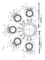
- Fig. 1 is a plan view of a vapor deposition system for containers equipped with a container conveyer device according to the present invention
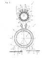
- Fig. 2 is an enlarged plan view of the vapor deposition system (only one vapor deposition device 1 is shown here due to the space of the drawing).
- the vapor deposition system works to deposit the vapor of a functional starting material on the inner surfaces of the containers by utilizing microwaves while the containers move through the vapor deposition system from the upstream side thereof to the downstream side thereof.
- the containers 25 flow to a feed conveyer 2 positioned on the upstream of the vapor deposition system, container feed wheel 3, conveyer wheel 4, container hand-over devices (delivery robots) 5, 6, and to the vapor deposition device 1, and are returned back again to the container hand-over devices 5, 6 and to the conveyer wheel 4, and, further, flow from the conveyer wheel 4 to a container discharge wheel 7 and to a discharge conveyer 8.
- the side of the feed conveyer 2 is regarded to be the upstream side and the side of the discharge conveyer 8 is regarded to be the downstream side along the flow of the steps for treating the containers 25.
- the feed conveyer 2 conveys the containers 25 in a linear direction of an arrow a in an erected attitude with their openings facing upward.
- a timing screw 39 is provided on the downstream of the feed conveyer 2, and the containers 25 are conveyed upon being contacted to a groove 39a of the timing screw 39 and are handed at a hand-over point b over to the container feed wheel 3.
- the container feed wheel 3 has a rotary shaft 3a that is rotatably supported by a base plate 42 for feed wheel via a bearing 45.
- a wheel surface of a rotary wheel 3b is arranged in a horizontal direction on the upper part of the rotary shaft 3a, and a container inner guide 40 is provided at the outer circumferential portion thereof in the radial direction.
- the inner guide 40 has annular guide plates 40a, and container limiting portions 40b of the shape of a curved groove are formed in the outer circumferential side surfaces of the guide plates 40a.
- the container limiting portions 40b work in cooperation with the groove 39a of the timing screw 39 enabling the container feed wheel 3 to receive the containers 25.
- the guide plates 40a are provided maintaining a gap in the up-and-down direction so as to support an upper part and a lower part of the container at an intermediate position thereof.
- the container feed wheel 3 is provided with an outer guide 41, and the containers 25 are conveyed between the inner guide 40 limited by the limiting portions 40b and the outer guide 41.
- the outer guide 41 is arranged between a hand-over point b and a hand-over point d shown in Fig. 2 .
- the outer guide 41 is supported by a support rod 44 erected on an L-shaped bracket 43 which is attached to a side wall of the base plate 42 for feed wheel.
- the outer guide is provided with a bottom plate 41a for supporting the container 25 and arcuate guide plates 41b for supporting the peripheral walls of the containers.
- the guide plates 41b are arranged maintaining a gap in the up-and-down direction.
- the container feed wheel 3 rotates being driven by a servo motor 46. That is, the servo motor 46 is arranged at a lower portion of the conveyer wheel 4.
- a belt 49 runs between a pulley 47a at an intermediate position of a main shaft 46a thereof in the up-and-down direction and a pulley 47b attached to a lower part of a rotary shaft 48a of an intermediate gear body 48 provided for the base plate 42 for feed wheel.
- An intermediate gear 48b is attached to the rotary shaft 48a of the intermediate gear body 48, and is in mesh with a gear 3c that is attached to the rotary shaft 3a of the container feed wheel 3. Therefore, the driving force of the servo motor 46 is transmitted to the container feed wheel 3 in order of servo motor 46, belt 49, intermediate gear 48b and gear 3c, and the rotary wheel 3b rotates.
- the conveyer wheel 4 has a circular inner conveyer passage 9 and an outer conveyer passage 10 which are in concentric with the rotary shaft, the inner and outer conveyer passages 9 and 10 rotating in the clockwise direction indicated by an arrow e.
- the inner conveyer passage 9 is provided with arcuate inner guides 50, and container support portions 50a of the shape of a curved groove are provided in a plural number in the outer circumferential side surface thereof maintaining an equal distance in the circumferential direction.
- the circular track of the container support portions 50a comes in contact with the circular track of the container feed wheel 3 at the hand-over position d, and works in cooperation with the container limiting portions 40b of the container feed wheel 3, so that the container support portions 50a receive the containers at the hand-over position d.
- the inner conveyer passage 9 is supported on a base plate 53 for supporting the conveyer wheel or, more closely, is supported by an annular inner wheel guide member 55 fixed to an upper surface of a bracket 54 of a U-shape in cross section that is placed on the base plate 53 for supporting the conveyer wheel. That is, an inner wheel gear 56 of the inner conveyer passage 9 is arranged in the inner circumferential surface of the wheel gear guide member 55 so as to freely slide therein, and an annular bearing 57 is provided at the sliding portion so that the inner wheel gear 56 rotates sliding in the inner circumferential surface of the inner wheel guide member 55.
- the inner conveyer passage 9 is provided with a bottom plate 50b for placing the containers thereon, and the inner guides 50 are supported on the bottom plate 50b.
- the inner guides 50 are provided in a number of two maintaining a gap in the up-and-down direction so as to support the upper part and the lower part of the containers at the intermediate position thereof.
- Teeth are formed in the inner circumferential surface of the inner wheel gear 56 and are in mesh with a main gear 46b attached to an upper part of the main shaft 46a of the servo motor 46 so as to be rotated by the driving force of the servo motor 46.
- a support plate 54a is provided at an upper part of the bracket 54, and an outer guide 51 is arranged at a further upper part of the support plate.
- the outer guide 51 is provided with arcuate guide plates 51a for supporting the circumferential wall portions of the containers.
- the guide plates 51a are provided in a number of two maintaining a gap in the up-and-down direction.
- the outer guide 51 is arranged starting from the hand-over position d of the inner conveyer passage 9 up to the container discharge wheel 7 (see Fig. 3 ).
- the conveyer wheel 4 conveys the containers up to the hand-over area f of the inner conveyer passage 9 so as to hand the containers over to the hand-over devices 5, 6.
- the hand-over devices 5, 6 can turn (reversely turn) toward the side of the vapor deposition device 1 about the rotary shaft.
- Fig. 8 is an enlarged sectional view of the vapor deposition device 1.
- the vapor deposition device 1 is provided with a turntable 14 which rotates in the clockwise direction as indicated by an arrow g.
- a plurality of vapor deposition units 15 are arranged on the outer circumferential portion of the turntable 14.
- the vapor deposition units 15 are arranged in a number of 16 in the circumferential direction of the turntable 14, wherein the pairs are each constituted by two vapor deposition units 15 and are integrally arranged.
- the vapor deposition units 15 can move along a circular track in concentric accompanying the rotary motion of the turntable 14.
- the vapor deposition unit 15 is provided with a pressure-reducing chamber 24 of a circular shape in transverse cross section and to which a vacuum pump that is not shown is connected to reduce the pressure in the chamber.
- the vapor deposition unit 15 is provided with a waveguide 32 communicated with the pressure-reducing chamber 24.
- a microwave oscillator 34 is present near the waveguide 32.
- the microwave oscillators 34 are fixed on the outer side of the turntable 14, and are provided in a number of four in this embodiment.
- the microwave oscillators 34 are arranged at positions on the side opposite to the hand-over devices 5, 6 in the radial direction of the turntable 14.
- the four (plurality of) microwave oscillators 34 are arranged being corresponded to the plurality of (four) vapor deposition units 15 consecutively arranged in the circumferential direction. Therefore, the four adjacent containers 25 can be vapor-deposited simultaneously.
- the container hand-over devices 5, 6 work to feed the containers 25 into the pressure-reducing chambers 24 as well as to take them out therefrom.
- the hand-over devices 5, 6 can take out or introduce the containers 25 from or into the four vapor deposition units 15 arranged at a position indicated as a first stage in Fig. 8 .
- the hand-over devices 5, 6 hand the containers 25 over to the outer conveyer passage 10.
- arcuate inner guides 60 are provided for the outer conveyer passage 10, and container support portions 60a of the shape of a curved groove are formed in a plural number in the outer circumferential portions of the inner guides 60 in the circumferential direction.
- the outer conveyer passage 10 rotates in the clockwise direction of an arrow e and hands the containers over to the container discharge wheel 7 at a hand-over position i.
- the circular track of the container support portions 60a comes in contact with the circular track of the container discharge wheel 7 at the hand-over position i where the containers are handed from the container support portions 60a over to the container discharge wheel 7.
- the container support portions 60a are arranged in a plural number in the circumferential direction of the outer conveyer passage 10 maintaining an equal distance.
- the container support portion 60a are formed maintaining the same pitch as that of the container support portions 50a of the inner conveyer passage 9.
- the outer conveyer passage 10 is supported on the base plate 53 for supporting the conveyer wheel or, more closely, is supported by an outer wheel guide member 65 attached to the base plate 53 for supporting the conveyer wheel. That is, an outer wheel gear 66 of the outer conveyer passage 10 is arranged along the outer circumferential surface of the outer wheel guide member 65 so as to freely slide therein, and an annular bearing 67 is provided at the sliding portion so that the outer wheel gear 66 rotates relative to the outer circumferential surface of the outer wheel guide member 65.
- the outer conveyer passage 10 is provided with a bottom plate 60b for supporting the containers, and the inner guides 60 are supported on the bottom plate 60b.
- the inner guides 60 are provided maintaining a gap in the up-and-down direction so as to support the upper part and the lower part of the containers at the intermediate position thereof.
- Teeth are formed in the outer circumferential surface of the outer wheel gear 66 and are in direct mesh with a main gear 68b attached to an upper part of the main shaft 68a of the servo motor 68, and the outer wheel gear 66 is rotated by the driving force of the servo motor 68.
- a support frame 64 is attached to the side portion of the base plate 53 for supporting the conveyer wheel, a support plate 64a is provided at an upper part of the support frame 64, and an outer guide 61 is arranged at a further upper part of the support plate 64a.
- the outer guide 61 is provided with arcuate guide plates 64b for supporting the circumferential wall portions of the containers 25.
- the guide plates 64b are provided maintaining a gap in the up-and-down direction.
- the outer guide 61 is arranged starting from the position of the container feed wheel 3 up to the hand-over position i which is an end point(see Fig. 3 ).
- the inner conveyer passage 9 and the outer conveyer passage 10 are so constituted as to rotate independently from each other, the position of height of the inner conveyer passage 9 being higher than the position of height of the outer conveyer passage 10.
- the container discharge wheel 7 has a rotary shaft 7a that is rotatably supported by base plate 62 for take-out wheel via a bearing 63.
- a rotary wheel 7b is arranged in a horizontal direction on the upper part of the rotary shaft 7a.
- Inner guides 70 of the form of an annular plate are provided at the outer circumferential portion of the container discharge wheel 7 facing in the horizontal direction.
- Container limiting portions 70a of the shape of a curved groove are formed in the outer circumferential portions of the inner guides 70 in the circumferential direction thereof.
- the container discharge wheel 7 is provided with an outer guide 71 on the outer circumferential side thereof, and the containers 25 are conveyed between the container limiting portions 70a and the outer guide 71 at the hand-over position i.
- the outer guide 71 is arranged between the hand-over point i and the hand-over point k shown in Fig. 2 .
- the container limiting portions 70a work in cooperation with the container support portions 60a of the outer conveyer passage 10 enabling the container discharge wheel 7 to receive the containers 25.
- the inner guides 70 are provided maintaining a gap in the up-and-down direction so as to support the upper part and the lower part of the containers at the intermediate position thereof.
- the outer guide 71 is constituted in the same manner as the outer guide 41 of the container feed wheel 3.
- the container discharge wheel 7 rotates being driven by the servo motor 68. That is, the servo motor 68 has a belt 76 that runs between a pulley 68c at an intermediate position of the main shaft 68a thereof in the up-and-down direction and a pulley 7c attached to the rotary shaft 7a of the container discharge wheel 7.
- the driving force of the servo motor 68 is transmitted to the container discharge wheel 7 via the belt 76, and the rotary wheel 7b rotates.
- the container discharge wheel 7 rotates in the counterclockwise direction of an arrow j, and the containers 25 are handed over at a hand-over position k of the discharge conveyer 8 shown in Fig. 11 extending in the tangential direction of the container discharge wheel 7 that is rotating.
- the discharge conveyer 8 conveys the containers 25 in the linear direction of an arrow m.
- the vapor deposition devices coating devices
- the container conveyer device of the present invention when the vapor deposition system starts operating, the containers 25 are consecutively conveyed by the feed conveyer 2 arranged at the position upstream of the vapor deposition system.
- the containers 25 are supported between the container limiting portions 40b of inner guide 40 of the container feed wheel 3 and the guide plates 41b of the outer guide 41.
- the containers 25 are fed to the conveyer wheel 4 at the hand-over position d of the inner conveyer passage 9 of the conveyer wheel 4 of which the rotary track contacts to that of the container feed wheel 3.
- the container feed wheel 3 consecutively feeds the containers 25 to the inner conveyer passage 9 of the conveyer wheel 4.
- the containers 25 are arranged in the container support portions 50a of the inner guide 50, and are consecutively conveyed clockwise between the inner guide 50 and the outer guide 51.
- the vapor deposition devices 1 are provided in a number of five on the outer side of the conveyer wheel 4 in the radial direction ( Fig. 2 shows only one of them). For instance, upon arriving at the container take-out position p of the conveyer wheel 4 facing the vapor deposition device 1a positioned on the downstream side, the four containers 25 of the first group are handed over to the four vapor deposition units 15 by the hand-over devices 5, 6 of the vapor-deposition device 1a.
- the containers 25 of the second group are handed over to the vapor deposition device 1b
- the containers 25 of the third group are handed over to the vapor deposition device 1c
- the containers 25 of the fourth group are handed over to the vapor deposition device 1d
- the containers 25 of the fifth group are handed over to the vapor deposition device 1e.
- the turntable 14 rotates at a regular interval each by 90 degrees from the first stage toward the second stage.
- the containers 25 are handed over by the above-mentioned container hand-over devices 5, 6 (see Fig. 1 ).
- the containers 25 conveyed from the first group up to the fifth group shown in Fig. 3 are all taken out from the inner conveyer passage 9, and are fed to the vapor deposition units 15.
- the turntable 14 is turned by 90 degrees to move the vapor deposition units 15 to the second stage.
- the vapor deposition units 15 arranged in the fourth stage are moved to the first stage due to the turn of the turntable 14.
- the container hand-over devices 5, 6 work to only feed the containers 25 to the vapor deposition units 15.
- the conveyer wheel 4 works to convey the container 25 at the head position n on the inner conveyer passage 9 of before the containers are taken out, up to the container take-out position p.
- the container hand-over devices 5, 6 work to feed the containers 25 which have not yet been vapor-deposited as received from the inner conveyer passage 9 into the vapor deposition units 15 from which the containers 25 have been taken out.
- the turntable 14 is turned by 90 degrees to move the vapor deposition units 15 to the third stage.
- the turntable 14 is, further, turned by 90 degrees to move the vapor deposition units 15 to the fourth stage.
- the turntable 14 is turned by 90 degrees, the containers 25 in the vapor deposition units 15 are arranged facing the hand-over devices 5, 6, and the containers 25 are handed over to the outer conveyer passage 10.
- the conveyer wheel 4 returns the containers 25 from the vapor deposition devices 1a to 1e back to the outer conveyer passage 10 through the hand-over devices 5, 6.
- the outer conveyer passage 10 rotates in the direction of an arrow e shown in Fig. 2 to convey the containers 25, and hand the containers 25 over to the container discharge wheel 7 at a hand-over position i.
- the containers 25 are stably conveyed between the inner guide 60 and the outer guide 61.
- the container limiting portions 70a of the inner guide 70 of the container discharge wheel 7 work in cooperation with the container support portions 60a of the outer conveyer passage 10 so that the containers 25 can be smoothly handed over from the outer conveyer passage 10 to the container discharge wheel 7.
- the container discharge wheel 7 stably conveys the containers 25 between the inner guide 70 and the outer guide 71.
- the containers 25 are turned by the container discharge wheel 7 in the counterclockwise direction of an arrow j, and are handed over to the discharge conveyer 8 at a hand-over position k.
- the discharge conveyer 8 conveys the containers 25 in the linear direction of an arrow m and feeds the containers 25 to the next step.
- the conveyer wheel 4 is rotatably arranged, and the conveyer passage is provided as inner and outer two routes in the radial direction, i.e., divided into the inner conveyer passage 9 on the side of feeding the containers 25 and the outer conveyer passage 10 on the side of taking out the containers, making it possible to convey the containers 25 at a high speed. That is, a plurality of branch passages or conveyer passage change-over points are not required unlike that of the conventional device shown in Fig. 12 . Therefore, no such time is required as waiting for the change over of the container conveyer passages, and the time for feeding and discharging the containers can be shortened.
- the plurality of vapor deposition devices 1a to 1e which are the container-treating devices are arranged in the circumferential direction of the circular conveyer wheel 4, the system as a whole does not extend in a linear direction. Therefore, the area for installation can be effectively utilized and can be decreased by about 30% as compared to that of the conventional systems.
- the hand-over devices 5, 6 work to hand over four containers 25 from the four vapor deposition units 15.
- the number of the containers 25 to be handed over by the hand-over devices 5, 6 is not limited to a plural number, but only one container may be handed over.
- robots were used as the hand-over devices 5, 6 as means for handing over the containers. According to the invention, however, any other means may be used instead of the robots.
Landscapes
- Engineering & Computer Science (AREA)
- Mechanical Engineering (AREA)
- Chemical & Material Sciences (AREA)
- General Chemical & Material Sciences (AREA)
- Chemical Kinetics & Catalysis (AREA)
- Materials Engineering (AREA)
- Metallurgy (AREA)
- Organic Chemistry (AREA)
- Specific Conveyance Elements (AREA)
Abstract
[Problems] To decrease the area for installing a container conveyer passage that has container hand-over devices on the way of the conveyer passage.
[Means for Solution] A container conveyer device including a conveyer passage that has a container feed position d where containers are received and a container discharge position i where the containers are handed over, and for conveying the containers from the container feed position d up to the container discharge position i, the container conveyer device, further, having container hand-over positions f, h where the containers that are once taken out from the conveyer passage are returned back again to the conveyer passage on the way of the container conveyer passage. A conveyer wheel 4 includes an inner conveyer passage 9 and an outer conveyer passage 10 that rotate about a rotary shaft, and conveyer hand-over means 5, 6 that hand over the containers between the inner conveyer passage 9 and the outer conveyer passage 10, and works to return the containers back to the outer conveyer passage 10 at the hand-over position h after the containers are taken out from the inner conveyer passage 9 at the container hand-over position f.
Description
- This invention relates to a container conveyer device equipped with a container conveyer passage along which there are container-treating steps, enabling the containers to be handed over to the container-treating steps from the conveyer passage on the way of round trips.
-
Fig. 12 illustrates asystem 151 using a conventional container conveyer device.
Thesystem 151 has a plurality of (five)devices 153 along aconveyer 152 that extends straight.
Theconveyer 152 includes a containerfeed conveyer passage 161 and a containerdischarge conveyer passage 162. The containerfeed conveyer passage 161 includes amain line 161a, conveyer passage change-over points at five places designated at P1, and fivebranch lines 161b branched from the change-over points P1. Similarly, the containerdischarge conveyer passage 162 includes amain line 162a, conveyer passage change-over points at four places designated at P2, and fourbranch lines 162b that meet themain line 162a at the change-over points P2.
Between theconveyer 152 and thedevices 153, conveyer hand-overdevices 157 are arranged to take a container from theconveyer 152 and to return it back to theconveyer 152. The container that is treated is returned back to theconveyer 152 and is conveyed to the next step. - The following
patent document 1 teaches that in a container conveyer device of a prior art, the containers are arranged in a row on a conveyer line, and electric charge portions are arranged on the way of the conveyer passage for forming a plurality of films. In order to treat a number of containers, however, thepatent document 1 teaches that the number of the discharge portions must be increased.
Arrangement of the plurality of discharge portions on the way of the conveyer passage, however, causes the device to become bulky making it difficult to shorten the time for forming the films. According to an embodiment of thepatent document 1, further, the containers conveyed in a row on the conveyer passage are held in a circular cassette that is capable of holding a plurality of containers, and many containers are conveyed into a film-forming chamber to form films on the containers.
Patent document 1: Japanese Unexamined Patent PublicationJP-A-2005-105306 - To convey the containers, the
conveyer 152 shown inFig. 12 is divided into the containerfeed conveyer passage 161 and the containerdischarge conveyer passage 162. Here, to flow the containers from themain line 161a to thebranch lines 161b or from thebranch lines 162b to themain line 162a, it becomes necessary to provide the conveyer passage change-over points P1, P2; i.e., conveyer passage change-over devices (not shown) are required in many number. Therefore, the change-over timings for conveying the containers become complex making it difficult to increase the speed for conveying the containers.
When, for example, the containers are preferentially fed from theupstream devices 153, successively, the containers are not often fed to thedownstream devices 153 making it difficult to conduct the processing to meet operating capability.
When the treating devices such as thedevices 153 are arranged in a plural number (five) in series on the way of theconveyer 152 along theconveyer 152 as described above, thesystem 151 becomes long in the direction of theconveyer 152 making it difficult to effectively utilize the area where it is installed resulting in an increase in the area where the system as a whole is installed. It is also allowable to install a conveyer for eachdevice 153. In this case, however, the conveyers are necessary in a number equal to the number of thedevices 153 making it, still, difficult to decrease the area for installation.
The present invention was accomplished in view of the above circumstances, and has an object of providing a container conveyer device which is capable of increasing the speed for conveying the containers on a container conveyer passage having container hand-over devices on the way of the container conveyer passage as well as decreasing the area on where a system as a whole is installed. - In order to achieve the above object, the container conveyer device of the present invention including a container feed position for receiving containers, a container discharge position for handing over the containers, a conveyer passage for conveying the containers from said container feed position up to said container discharge position, and a container hand-over position where the containers are once taken out from said conveyer passage and the containers are returned back again to said conveyer passage on the way of said conveyer passage, wherein, said conveyer passage includes an inner conveyer passage that rotates about a rotary shaft, an outer conveyer passage arranged on the outer circumferential side thereof on the same shaft, container feed means for feeding the containers at the container feed position on either said inner conveyer passage or said outer conveyer passage, and container discharge means for discharging the containers at the container discharge position on the other conveyer passage, the conveyer passage, further, including container hand-over means for returning the containers back to the other conveyer passage after the containers are taken out from the one conveyer passage at the container hand-over positions.
In the container conveyer device, the inner conveyer passage and the outer conveyer passage are independently controlled.
In the container conveyer device, the outer conveyer passage is arranged at a position of height equal to, or lower than, the position of height of the inner conveyer passage.
In the container conveyer device, the container feed means includes a rotary container feed wheel having container support portions, and has, at the container feed position, a contact portion between a container conveyer track of the container feed wheel and a container conveyer track of the one conveyer passage, to hand over the containers at the contact portion, and the container discharge means includes a rotary container discharge wheel having container support portions, and has, at the container discharge position, a contact portion between a container conveyer track of the container discharge wheel and a container conveyer track of the other conveyer passage, to hand over the containers at the contact portion.
In the container conveyer device, a plurality of said container hand-over means are provided along the circumferential direction of said conveyer passage. - In the container conveyer device of the present invention, the conveyer passage has the inner conveyer passage that rotates about the rotary shaft, the outer conveyer passage arranged on the outer circumferential side thereof, the conveyer feed means for feeding the containers to either the inner conveyer passage or the outer conveyer passage, and container discharge means for discharging the containers to the other conveyer passage, so that the containers are returned back to the other conveyer passage after the containers are taken out from the one conveyer passage at the container hand-over position. Further, the inner conveyer passage and the outer conveyer passage are independently controlled so that the containers can be fed and discharged at separate timings. It is, therefore, made possible to convey the containers at high speeds. More closely, unlike the conventional device (
Fig. 12 ), the container conveyer device does not require a plurality of branch passages or conveyer passage change-over points, does not require the time such as waiting for the change over of the container conveyer passages, and makes it possible to shorten the time for feeding and discharging the containers. Upon increasing the speed of conveyance, the containers can be conveyed to meet the treating capability of the device contributing to improving the production efficiency.
Despite there are a plurality of container-treating devices (vapor deposition devices) on the way of the conveyer passage, the system as a whole does not extend straight, and the area for installation can be effectively utilized. The conventional device was provided with the container feed conveyer passage and the container discharge conveyer passage or, substantially, with four conveyer passages inclusive of branch passages to convey the containers requiring an increased area for installation. The present invention, on the other hand, requires the container feed conveyer passage and the discharge conveyer passage only, though the conveyer passages have dissimilar shapes, making it possible to decrease the area for installation. -
- [
Fig. 1 ] is a schematic plan view of a vapor deposition system equipped with a container conveyer device of the present invention. - [
Fig. 2 ] is a schematic enlarged plan view illustrating the vapor deposition system ofFig. 1 in a simplified manner. - [
Fig. 3 ] is a plan view of the container conveyer device in the vapor deposition system ofFig. 1 . - [
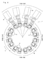
Fig. 4 ] is a plan view illustrating a driving system for the container conveyer device in the vapor deposition system ofFig. 1 . - [
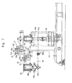
Fig. 5 ] is a sectional view on the container feed side of the container conveyer device in a direction of a line A-A inFig. 4 . - [
Fig. 6 ] is a sectional view on the container feed side of the container conveyer device in a direction of a line B-B inFig. 4 . - [
Fig. 7 ] is a sectional view on the container feed side of the container conveyer device in a direction of a line C-C inFig. 4 . - [
Fig. 8 ] is an enlarged plan view of a vapor deposition device in the vapor deposition system ofFig. 1 . - [
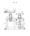
Fig. 9 ] is a sectional view on the container discharge side of the container conveyer device in a direction of a line D-D inFig. 4 . - [
Fig. 10 ] is a sectional view on the container discharge side of the container conveyer device in a direction of a line E-E inFig. 4 . - [
Fig. 11 ] is a sectional view on the container discharge side of the container conveyer device in a direction of a line F-F inFig. 4 . - [
Fig. 12 ] is a schematic plan view of a conventional vapor deposition system. -
- 1(1a to 1e)
- vapor deposition devices
- 2
- feed conveyer
- 3
- container feed wheel
- 3a
- rotary shaft
- 3b, 7b
- rotary wheels
- 3c
- gear
- 4
- conveyer wheel
- 5, 6
- container hand-over devices
- 7
- container discharge wheel
- 7a, 48a
- rotary shafts
- 7c, 47a, 47b, 68c
- pulleys
- 8
- discharge conveyer
- 9
- inner conveyer passage
- 10
- outer conveyer passage
- 14
- turntable
- 15
- vapor deposition units
- 24
- pressure-reducing chambers
- 25
- containers
- 34
- microwave oscillators
- 39
- timing screw
- 39a
- groove
- 40
- inner guide
- 40a
- guide plates
- 40b
- container limiting portions
- 41
- outer guide
- 41a
- bottom plate
- 41b
- guide plates
- 42
- base plate for feed wheel
- 43, 54
- brackets
- 44
- support rod
- 45, 63
- bearings
- 46, 68
- servo motors
- 46a
- main shaft
- 46b, 68b
- main gears
- 48
- intermediate gear body
- 48a
- rotary shaft
- 48b
- intermediate gear
- 49, 76
- belts
- 50, 60, 70
- inner guides
- 50a
- container support portions
- 50b, 60b
- bottom plates
- 51, 61, 71
- container outer guides
- 51a, 64b, 74b
- guide plates
- 53
- base plate for supporting conveyer wheel
- 54a,
- 64a support plates
- 55
- inner wheel guide member
- 56
- inner wheel gear
- 57, 67
- bearings
- 60a
- container support portions
- 62
- base plate for take-out wheel
- 64
- support frame
- 65
- outer wheel guide member
- 66
- outer wheel gear
- 68a
- main shaft
- 70a
- container limiting portions
- d
- container feed position
- i
- container discharge position
- f, h
- container hand-over positions
-
Fig. 1 is a plan view of a vapor deposition system for containers equipped with a container conveyer device according to the present invention, andFig. 2 is an enlarged plan view of the vapor deposition system (only onevapor deposition device 1 is shown here due to the space of the drawing).
The vapor deposition system works to deposit the vapor of a functional starting material on the inner surfaces of the containers by utilizing microwaves while the containers move through the vapor deposition system from the upstream side thereof to the downstream side thereof. Thecontainers 25 flow to afeed conveyer 2 positioned on the upstream of the vapor deposition system,container feed wheel 3,conveyer wheel 4, container hand-over devices (delivery robots) 5, 6, and to thevapor deposition device 1, and are returned back again to the container hand-overdevices conveyer wheel 4, and, further, flow from theconveyer wheel 4 to acontainer discharge wheel 7 and to adischarge conveyer 8. In this embodiment, the side of thefeed conveyer 2 is regarded to be the upstream side and the side of thedischarge conveyer 8 is regarded to be the downstream side along the flow of the steps for treating thecontainers 25. - Referring to
Fig. 3 to Fig. 5 , thefeed conveyer 2 conveys thecontainers 25 in a linear direction of an arrow a in an erected attitude with their openings facing upward. Atiming screw 39 is provided on the downstream of thefeed conveyer 2, and thecontainers 25 are conveyed upon being contacted to agroove 39a of thetiming screw 39 and are handed at a hand-over point b over to thecontainer feed wheel 3.
Thecontainer feed wheel 3 has arotary shaft 3a that is rotatably supported by abase plate 42 for feed wheel via abearing 45. A wheel surface of arotary wheel 3b is arranged in a horizontal direction on the upper part of therotary shaft 3a, and a containerinner guide 40 is provided at the outer circumferential portion thereof in the radial direction. Theinner guide 40 hasannular guide plates 40a, andcontainer limiting portions 40b of the shape of a curved groove are formed in the outer circumferential side surfaces of theguide plates 40a. Thecontainer limiting portions 40b work in cooperation with thegroove 39a of thetiming screw 39 enabling thecontainer feed wheel 3 to receive thecontainers 25. Theguide plates 40a are provided maintaining a gap in the up-and-down direction so as to support an upper part and a lower part of the container at an intermediate position thereof. - The
container feed wheel 3 is provided with anouter guide 41, and thecontainers 25 are conveyed between theinner guide 40 limited by the limitingportions 40b and theouter guide 41. Theouter guide 41 is arranged between a hand-over point b and a hand-over point d shown inFig. 2 .
Referring toFig. 6 , theouter guide 41 is supported by asupport rod 44 erected on an L-shapedbracket 43 which is attached to a side wall of thebase plate 42 for feed wheel. The outer guide is provided with abottom plate 41a for supporting thecontainer 25 andarcuate guide plates 41b for supporting the peripheral walls of the containers. Theguide plates 41b are arranged maintaining a gap in the up-and-down direction. - Referring to
Fig. 6 andFig. 7 , thecontainer feed wheel 3 rotates being driven by aservo motor 46. That is, theservo motor 46 is arranged at a lower portion of theconveyer wheel 4. Abelt 49 runs between apulley 47a at an intermediate position of amain shaft 46a thereof in the up-and-down direction and apulley 47b attached to a lower part of arotary shaft 48a of anintermediate gear body 48 provided for thebase plate 42 for feed wheel. Anintermediate gear 48b is attached to therotary shaft 48a of theintermediate gear body 48, and is in mesh with agear 3c that is attached to therotary shaft 3a of thecontainer feed wheel 3. Therefore, the driving force of theservo motor 46 is transmitted to thecontainer feed wheel 3 in order ofservo motor 46,belt 49,intermediate gear 48b andgear 3c, and therotary wheel 3b rotates. - Referring to
Fig. 2 andFig. 3 , theconveyer wheel 4 has a circularinner conveyer passage 9 and anouter conveyer passage 10 which are in concentric with the rotary shaft, the inner andouter conveyer passages
Theinner conveyer passage 9 is provided with arcuate inner guides 50, andcontainer support portions 50a of the shape of a curved groove are provided in a plural number in the outer circumferential side surface thereof maintaining an equal distance in the circumferential direction. The circular track of thecontainer support portions 50a comes in contact with the circular track of thecontainer feed wheel 3 at the hand-over position d, and works in cooperation with thecontainer limiting portions 40b of thecontainer feed wheel 3, so that thecontainer support portions 50a receive the containers at the hand-over position d. - Referring to
Fig. 7 , theinner conveyer passage 9 is supported on abase plate 53 for supporting the conveyer wheel or, more closely, is supported by an annular innerwheel guide member 55 fixed to an upper surface of abracket 54 of a U-shape in cross section that is placed on thebase plate 53 for supporting the conveyer wheel. That is, aninner wheel gear 56 of theinner conveyer passage 9 is arranged in the inner circumferential surface of the wheelgear guide member 55 so as to freely slide therein, and anannular bearing 57 is provided at the sliding portion so that theinner wheel gear 56 rotates sliding in the inner circumferential surface of the innerwheel guide member 55.
Theinner conveyer passage 9 is provided with abottom plate 50b for placing the containers thereon, and theinner guides 50 are supported on thebottom plate 50b. The inner guides 50 are provided in a number of two maintaining a gap in the up-and-down direction so as to support the upper part and the lower part of the containers at the intermediate position thereof. - Teeth are formed in the inner circumferential surface of the
inner wheel gear 56 and are in mesh with amain gear 46b attached to an upper part of themain shaft 46a of theservo motor 46 so as to be rotated by the driving force of theservo motor 46.
Asupport plate 54a is provided at an upper part of thebracket 54, and anouter guide 51 is arranged at a further upper part of the support plate. Theouter guide 51 is provided witharcuate guide plates 51a for supporting the circumferential wall portions of the containers. Theguide plates 51a are provided in a number of two maintaining a gap in the up-and-down direction. Theouter guide 51 is arranged starting from the hand-over position d of theinner conveyer passage 9 up to the container discharge wheel 7 (seeFig. 3 ).
As shown inFig. 2 , theconveyer wheel 4 conveys the containers up to the hand-over area f of theinner conveyer passage 9 so as to hand the containers over to the hand-overdevices devices vapor deposition device 1 about the rotary shaft. -
Fig. 8 is an enlarged sectional view of thevapor deposition device 1.
Thevapor deposition device 1 is provided with aturntable 14 which rotates in the clockwise direction as indicated by an arrow g. A plurality ofvapor deposition units 15 are arranged on the outer circumferential portion of theturntable 14. In this embodiment, thevapor deposition units 15 are arranged in a number of 16 in the circumferential direction of theturntable 14, wherein the pairs are each constituted by twovapor deposition units 15 and are integrally arranged. Thevapor deposition units 15 can move along a circular track in concentric accompanying the rotary motion of theturntable 14.
Thevapor deposition unit 15 is provided with a pressure-reducingchamber 24 of a circular shape in transverse cross section and to which a vacuum pump that is not shown is connected to reduce the pressure in the chamber. Thevapor deposition unit 15 is provided with a waveguide 32 communicated with the pressure-reducingchamber 24. Amicrowave oscillator 34 is present near the waveguide 32. - The
microwave oscillators 34 are fixed on the outer side of theturntable 14, and are provided in a number of four in this embodiment. Themicrowave oscillators 34 are arranged at positions on the side opposite to the hand-overdevices turntable 14. The four (plurality of)microwave oscillators 34 are arranged being corresponded to the plurality of (four)vapor deposition units 15 consecutively arranged in the circumferential direction. Therefore, the fouradjacent containers 25 can be vapor-deposited simultaneously.
The container hand-overdevices containers 25 into the pressure-reducingchambers 24 as well as to take them out therefrom. The hand-overdevices containers 25 from or into the fourvapor deposition units 15 arranged at a position indicated as a first stage inFig. 8 . In a hand-over area h of theconveyer wheel 4 shown inFig. 2 , the hand-overdevices containers 25 over to theouter conveyer passage 10. - Referring to
Fig. 2 andFig. 3 , arcuate inner guides 60 are provided for theouter conveyer passage 10, andcontainer support portions 60a of the shape of a curved groove are formed in a plural number in the outer circumferential portions of theinner guides 60 in the circumferential direction.
Theouter conveyer passage 10 rotates in the clockwise direction of an arrow e and hands the containers over to thecontainer discharge wheel 7 at a hand-over position i. The circular track of thecontainer support portions 60a comes in contact with the circular track of thecontainer discharge wheel 7 at the hand-over position i where the containers are handed from thecontainer support portions 60a over to thecontainer discharge wheel 7.
Thecontainer support portions 60a are arranged in a plural number in the circumferential direction of theouter conveyer passage 10 maintaining an equal distance. Thecontainer support portion 60a are formed maintaining the same pitch as that of thecontainer support portions 50a of theinner conveyer passage 9. - Referring to
Fig. 9 andFig. 10 , theouter conveyer passage 10 is supported on thebase plate 53 for supporting the conveyer wheel or, more closely, is supported by an outerwheel guide member 65 attached to thebase plate 53 for supporting the conveyer wheel. That is, anouter wheel gear 66 of theouter conveyer passage 10 is arranged along the outer circumferential surface of the outerwheel guide member 65 so as to freely slide therein, and anannular bearing 67 is provided at the sliding portion so that theouter wheel gear 66 rotates relative to the outer circumferential surface of the outerwheel guide member 65.
Theouter conveyer passage 10 is provided with abottom plate 60b for supporting the containers, and theinner guides 60 are supported on thebottom plate 60b. The inner guides 60 are provided maintaining a gap in the up-and-down direction so as to support the upper part and the lower part of the containers at the intermediate position thereof. - Teeth are formed in the outer circumferential surface of the
outer wheel gear 66 and are in direct mesh with amain gear 68b attached to an upper part of themain shaft 68a of theservo motor 68, and theouter wheel gear 66 is rotated by the driving force of theservo motor 68.
Asupport frame 64 is attached to the side portion of thebase plate 53 for supporting the conveyer wheel, asupport plate 64a is provided at an upper part of thesupport frame 64, and anouter guide 61 is arranged at a further upper part of thesupport plate 64a. Theouter guide 61 is provided witharcuate guide plates 64b for supporting the circumferential wall portions of thecontainers 25. Theguide plates 64b are provided maintaining a gap in the up-and-down direction. Theouter guide 61 is arranged starting from the position of thecontainer feed wheel 3 up to the hand-over position i which is an end point(seeFig. 3 ).
As described above, theinner conveyer passage 9 and theouter conveyer passage 10 are so constituted as to rotate independently from each other, the position of height of theinner conveyer passage 9 being higher than the position of height of theouter conveyer passage 10. - The
container discharge wheel 7 has arotary shaft 7a that is rotatably supported bybase plate 62 for take-out wheel via abearing 63. Arotary wheel 7b is arranged in a horizontal direction on the upper part of therotary shaft 7a. Inner guides 70 of the form of an annular plate are provided at the outer circumferential portion of thecontainer discharge wheel 7 facing in the horizontal direction.Container limiting portions 70a of the shape of a curved groove are formed in the outer circumferential portions of theinner guides 70 in the circumferential direction thereof.
Referring toFig. 3 , thecontainer discharge wheel 7 is provided with an outer guide 71 on the outer circumferential side thereof, and thecontainers 25 are conveyed between thecontainer limiting portions 70a and the outer guide 71 at the hand-over position i. The outer guide 71 is arranged between the hand-over point i and the hand-over point k shown inFig. 2 .
Thecontainer limiting portions 70a work in cooperation with thecontainer support portions 60a of theouter conveyer passage 10 enabling thecontainer discharge wheel 7 to receive thecontainers 25. The inner guides 70 are provided maintaining a gap in the up-and-down direction so as to support the upper part and the lower part of the containers at the intermediate position thereof. The outer guide 71 is constituted in the same manner as theouter guide 41 of thecontainer feed wheel 3. - Referring to
Fig. 10 , thecontainer discharge wheel 7 rotates being driven by theservo motor 68. That is, theservo motor 68 has abelt 76 that runs between apulley 68c at an intermediate position of themain shaft 68a thereof in the up-and-down direction and apulley 7c attached to therotary shaft 7a of thecontainer discharge wheel 7. The driving force of theservo motor 68 is transmitted to thecontainer discharge wheel 7 via thebelt 76, and therotary wheel 7b rotates.
Referring toFig. 2 , thecontainer discharge wheel 7 rotates in the counterclockwise direction of an arrow j, and thecontainers 25 are handed over at a hand-over position k of thedischarge conveyer 8 shown inFig. 11 extending in the tangential direction of thecontainer discharge wheel 7 that is rotating.
Thedischarge conveyer 8 conveys thecontainers 25 in the linear direction of an arrow m. - Next, described below is an example in which the vapor deposition devices (coating devices) are arranged for the container conveyer device of the present invention.
Referring toFig. 3 , when the vapor deposition system starts operating, thecontainers 25 are consecutively conveyed by thefeed conveyer 2 arranged at the position upstream of the vapor deposition system. At the hand-over position b of thefeed conveyer 2, thecontainers 25 are supported between thecontainer limiting portions 40b ofinner guide 40 of thecontainer feed wheel 3 and theguide plates 41b of theouter guide 41. Thereafter, thecontainers 25 are fed to theconveyer wheel 4 at the hand-over position d of theinner conveyer passage 9 of theconveyer wheel 4 of which the rotary track contacts to that of thecontainer feed wheel 3. Thus, thecontainer feed wheel 3 consecutively feeds thecontainers 25 to theinner conveyer passage 9 of theconveyer wheel 4. On theinner conveyer passage 9, thecontainers 25 are arranged in thecontainer support portions 50a of theinner guide 50, and are consecutively conveyed clockwise between theinner guide 50 and theouter guide 51. - Referring to
Fig. 1 andFig. 3 , thevapor deposition devices 1 are provided in a number of five on the outer side of theconveyer wheel 4 in the radial direction (Fig. 2 shows only one of them). For instance, upon arriving at the container take-out position p of theconveyer wheel 4 facing thevapor deposition device 1a positioned on the downstream side, the fourcontainers 25 of the first group are handed over to the fourvapor deposition units 15 by the hand-overdevices deposition device 1a. At the same time, thecontainers 25 of the second group are handed over to thevapor deposition device 1b, thecontainers 25 of the third group are handed over to thevapor deposition device 1c, thecontainers 25 of the fourth group are handed over to thevapor deposition device 1d, and thecontainers 25 of the fifth group are handed over to thevapor deposition device 1e. After thecontainers 25 are handed over to thevapor deposition devices 1a to 1e, thecontainers 25 following the head position n of before the containers are taken out are subsequently conveyed on theinner conveyer passage 9. - Referring to
Fig. 8 , theturntable 14 rotates at a regular interval each by 90 degrees from the first stage toward the second stage. In the first stage, thecontainers 25 are handed over by the above-mentioned container hand-overdevices 5, 6 (seeFig. 1 ). At this moment, thecontainers 25 conveyed from the first group up to the fifth group shown inFig. 3 are all taken out from theinner conveyer passage 9, and are fed to thevapor deposition units 15. After thecontainers 25 have been handed over, theturntable 14 is turned by 90 degrees to move thevapor deposition units 15 to the second stage. - At the same time, the
vapor deposition units 15 arranged in the fourth stage are moved to the first stage due to the turn of theturntable 14. When the vapor-deposited containers have not yet been held in thevapor deposition units 15 like in the initial stage of the vapor deposition work, the container hand-overdevices containers 25 to thevapor deposition units 15.
At this moment, theconveyer wheel 4 works to convey thecontainer 25 at the head position n on theinner conveyer passage 9 of before the containers are taken out, up to the container take-out position p. Thereafter, the container hand-overdevices containers 25 which have not yet been vapor-deposited as received from theinner conveyer passage 9 into thevapor deposition units 15 from which thecontainers 25 have been taken out.
When thecontainers 25 are vapor-deposited after one cycle has been finished, the vapor-deposited containers have been held in the pressure-reducingchambers 24. Therefore, the hand-overdevices containers 25 in the hand-over area f of theinner conveyer passage 9, and hand thecontainers 25 over to theouter conveyer passage 10.
After the end of the second stage, theturntable 14 is turned by 90 degrees to move thevapor deposition units 15 to the third stage. - After the
containers 25 are vapor-deposited in the third stage, theturntable 14 is, further, turned by 90 degrees to move thevapor deposition units 15 to the fourth stage.
After the fourth stage has been finished, theturntable 14 is turned by 90 degrees, thecontainers 25 in thevapor deposition units 15 are arranged facing the hand-overdevices containers 25 are handed over to theouter conveyer passage 10.
Theconveyer wheel 4 returns thecontainers 25 from thevapor deposition devices 1a to 1e back to theouter conveyer passage 10 through the hand-overdevices - The
outer conveyer passage 10 rotates in the direction of an arrow e shown inFig. 2 to convey thecontainers 25, and hand thecontainers 25 over to thecontainer discharge wheel 7 at a hand-over position i. Thecontainers 25 are stably conveyed between theinner guide 60 and theouter guide 61.
At the hand-over position i, thecontainer limiting portions 70a of theinner guide 70 of thecontainer discharge wheel 7 work in cooperation with thecontainer support portions 60a of theouter conveyer passage 10 so that thecontainers 25 can be smoothly handed over from theouter conveyer passage 10 to thecontainer discharge wheel 7. Thecontainer discharge wheel 7 stably conveys thecontainers 25 between theinner guide 70 and the outer guide 71.
Thecontainers 25 are turned by thecontainer discharge wheel 7 in the counterclockwise direction of an arrow j, and are handed over to thedischarge conveyer 8 at a hand-over position k.
Thedischarge conveyer 8 conveys thecontainers 25 in the linear direction of an arrow m and feeds thecontainers 25 to the next step. - In this embodiment as described above, the
conveyer wheel 4 is rotatably arranged, and the conveyer passage is provided as inner and outer two routes in the radial direction, i.e., divided into theinner conveyer passage 9 on the side of feeding thecontainers 25 and theouter conveyer passage 10 on the side of taking out the containers, making it possible to convey thecontainers 25 at a high speed. That is, a plurality of branch passages or conveyer passage change-over points are not required unlike that of the conventional device shown inFig. 12 . Therefore, no such time is required as waiting for the change over of the container conveyer passages, and the time for feeding and discharging the containers can be shortened.
Further, since the plurality ofvapor deposition devices 1a to 1e which are the container-treating devices are arranged in the circumferential direction of thecircular conveyer wheel 4, the system as a whole does not extend in a linear direction. Therefore, the area for installation can be effectively utilized and can be decreased by about 30% as compared to that of the conventional systems. - Though the invention was described above in detail by way of an embodiment with reference to the accompanying drawings, it should be noted that the invention is in no way limited to the above embodiment only but can be altered or modified in various other ways without departing from the scope of the invention.
In the above embodiment, the hand-overdevices containers 25 from the fourvapor deposition units 15. However, the number of thecontainers 25 to be handed over by the hand-overdevices
In the above embodiment, robots were used as the hand-overdevices
According to the invention, however, any other means may be used instead of the robots.
Claims (6)
- A container conveyer device including a container feed position for receiving containers, a container discharge position for handing over the containers, a conveyer passage for conveying the containers from said container feed position up to said container discharge position, and a container hand-over position where the containers are once taken out from said conveyer passage and the containers are returned back again to said conveyer passage on the way of said conveyer passage,
wherein:said conveyer passage includes an inner conveyer passage that rotates about a rotary shaft, an outer conveyer passage arranged on the outer circumferential side thereof on the same shaft, container feed means for feeding the containers at the container feed position on either said inner conveyer passage or said outer conveyer passage, and container discharge means for discharging the containers at the container discharge position on the other conveyer passage;the conveyer passage, further, including container hand-over means for returning the containers back to said other conveyer passage after the containers are taken out from said one conveyer passage at said container hand-over positions. - The container conveyer device according to claim 1,
wherein said inner conveyer passage and said outer conveyer passage are independently controlled. - The container conveyer device according to claim 1 or 2,
wherein said outer conveyer passage is arranged at a position of height equal to, or lower than, the position of height of said inner conveyer passage. - The container conveyer device according to any one of claims 1 to 3, wherein said container feed means includes a rotary container feed wheel having container support portions, and has, at the container feed position, a contact portion between a container conveyer track of said container feed wheel and a container conveyer track of said one conveyer passage, to hand over the containers at said contact portion, and said container discharge means includes a rotary container discharge wheel having container support portions, and has, at the container discharge position, a contact portion between a container conveyer track of said container discharge wheel and a container conveyer track of said other conveyer passage, to hand over the containers at said contact portion.
- The container conveyer device according to any one of claims 1 to 4, wherein a plurality of said container hand-over means are provided along the circumferential direction of said conveyer passage.
- The container conveyer device according to any one of claims 1 to 5, wherein coating devices are arranged on the outer circumferences of said container hand-over means to apply coatings onto the surfaces of the containers.
Applications Claiming Priority (1)
| Application Number | Priority Date | Filing Date | Title |
|---|---|---|---|
| PCT/JP2008/057696 WO2009130751A1 (en) | 2008-04-21 | 2008-04-21 | Container conveyance apparatus |
Publications (1)
| Publication Number | Publication Date |
|---|---|
| EP2179946A1 true EP2179946A1 (en) | 2010-04-28 |
Family
ID=41216501
Family Applications (1)
| Application Number | Title | Priority Date | Filing Date |
|---|---|---|---|
| EP08740738A Withdrawn EP2179946A1 (en) | 2008-04-21 | 2008-04-21 | Container conveyance apparatus |
Country Status (6)
| Country | Link |
|---|---|
| US (1) | US20100163367A1 (en) |
| EP (1) | EP2179946A1 (en) |
| JP (1) | JP5392078B2 (en) |
| KR (1) | KR20100136394A (en) |
| CN (1) | CN101678966A (en) |
| WO (1) | WO2009130751A1 (en) |
Families Citing this family (3)
| Publication number | Priority date | Publication date | Assignee | Title |
|---|---|---|---|---|
| DE102013202879A1 (en) * | 2013-02-21 | 2014-08-21 | Mall + Herlan Schweiz Ag | Feeding device and method for successive feeding |
| DE102013105460A1 (en) * | 2013-05-28 | 2014-12-04 | Khs Gmbh | Method for treating containers and container treatment machine |
| JPWO2023139875A1 (en) * | 2022-01-19 | 2023-07-27 |
Family Cites Families (19)
| Publication number | Priority date | Publication date | Assignee | Title |
|---|---|---|---|---|
| US3041805A (en) * | 1960-07-25 | 1962-07-03 | Fulco Charles | Packaging apparatus |
| JPS5141399B2 (en) * | 1973-06-04 | 1976-11-09 | ||
| US4124112A (en) * | 1977-05-23 | 1978-11-07 | Owens-Illinois, Inc. | Odd-shaped container indexing starwheel |
| JPS62265569A (en) * | 1986-05-13 | 1987-11-18 | Nittec Co Ltd | Method and device for conveying container |
| FR2648119B1 (en) * | 1989-06-09 | 1991-09-27 | Girondine Sa | DEVICE FOR TRANSPORTING CONTAINERS, SUCH AS BOTTLES |
| US5029695A (en) * | 1990-04-03 | 1991-07-09 | S. C. Johnson & Son, Inc. | Improved starwheel |
| EP0535946B1 (en) * | 1991-09-30 | 1996-07-31 | Kao Corporation | Article transportation processing system |
| DE4243010C1 (en) * | 1992-12-19 | 1994-05-26 | Kronseder Maschf Krones | Packing machine |
| DE19816239A1 (en) * | 1998-04-11 | 1999-10-14 | Krones Ag | Device for introducing and / or discharging containers into or from a treatment room |
| US6517691B1 (en) * | 1998-08-20 | 2003-02-11 | Intevac, Inc. | Substrate processing system |
| DE19952009A1 (en) * | 1999-10-28 | 2001-05-10 | Indag Gmbh | Device for placing bags in an outer packaging |
| US6889814B2 (en) * | 2001-05-30 | 2005-05-10 | Rapistan Systems Advertising Corp. | Article sortation system |
| AU2003229286A1 (en) * | 2002-05-24 | 2003-12-12 | Sig Technology Ltd. | Method and device for the plasma treatment of workpieces |
| WO2005021388A2 (en) * | 2003-08-28 | 2005-03-10 | Dayton Systems Group, Inc. | Container end forming system |
| DE10359392B3 (en) * | 2003-12-18 | 2005-05-04 | Khs Maschinen- Und Anlagenbau Ag | Sterilizing device for drink holder caps has first and second towers with parallel axes driven at equal circumferential speed |
| JP3809613B2 (en) * | 2004-08-06 | 2006-08-16 | 株式会社ニューギン | Game board transfer device |
| DE202005002470U1 (en) * | 2005-02-16 | 2005-11-10 | Krones Ag | Transport system for container handling machines |
| US7637708B2 (en) * | 2006-01-09 | 2009-12-29 | Sumco Corporation | Production system for wafer |
| US7398871B1 (en) * | 2006-01-11 | 2008-07-15 | Basgil Thomas M | Outsert placer |
-
2008
- 2008-04-21 JP JP2009516773A patent/JP5392078B2/en not_active Expired - Fee Related
- 2008-04-21 WO PCT/JP2008/057696 patent/WO2009130751A1/en not_active Ceased
- 2008-04-21 EP EP08740738A patent/EP2179946A1/en not_active Withdrawn
- 2008-04-21 KR KR1020097009060A patent/KR20100136394A/en not_active Withdrawn
- 2008-04-21 CN CN200880001320A patent/CN101678966A/en active Pending
- 2008-04-21 US US12/445,893 patent/US20100163367A1/en not_active Abandoned
Non-Patent Citations (1)
| Title |
|---|
| See references of WO2009130751A1 * |
Also Published As
| Publication number | Publication date |
|---|---|
| US20100163367A1 (en) | 2010-07-01 |
| JP5392078B2 (en) | 2014-01-22 |
| WO2009130751A1 (en) | 2009-10-29 |
| CN101678966A (en) | 2010-03-24 |
| JPWO2009130751A1 (en) | 2011-08-11 |
| KR20100136394A (en) | 2010-12-28 |
Similar Documents
| Publication | Publication Date | Title |
|---|---|---|
| US4526128A (en) | High-speed indexing feed screw conveyer | |
| EP2045187A1 (en) | Conveyance device and box packing device with the same | |
| KR20000010527A (en) | Improved star wheel equipment | |
| CN214242861U (en) | device for handling containers | |
| KR20080109603A (en) | Roller conveyor and conveying control method | |
| US11332325B2 (en) | Apparatus for coating containers with bypass and method for operating such an apparatus | |
| JP2017507786A (en) | Recirculation system and method for can and bottle making machine | |
| EP2032444A2 (en) | Machine and method for forming groups of products ordered in superposed layers | |
| EP0711719B1 (en) | Equally spaced product conveying method and line | |
| EP0894750A1 (en) | Method and unit for combined transfer-turnover of packets of cigarettes | |
| US9796539B2 (en) | Suction retaining device for retaining containers on a conveyor | |
| US20100163367A1 (en) | Container conveyer device | |
| JP5605657B2 (en) | Product transport unit | |
| US5797478A (en) | System for the ordered transfer of objects between at least two conveyor lines disposed substantially at a right angle to one another | |
| US20220018014A1 (en) | Vacuum processing apparatus | |
| EP4159646B1 (en) | Container processing system | |
| WO2023234010A1 (en) | Article conveyance device | |
| EP0942869A1 (en) | Apparatus for transferring rod-like articles | |
| US6283276B1 (en) | Overhead pusher finger guide system | |
| US6158570A (en) | Process and device for conveying and forming groups of discoid products, in particular biscuits | |
| EP1894863B1 (en) | Dosing apparatus | |
| EP1447357A1 (en) | Ordering apparatus for solid articles | |
| CN1098791C (en) | Unit for transferring tobacco articles | |
| JP2014227237A (en) | Carrying device | |
| JP2000053240A (en) | Container merging device |
Legal Events
| Date | Code | Title | Description |
|---|---|---|---|
| PUAI | Public reference made under article 153(3) epc to a published international application that has entered the european phase |
Free format text: ORIGINAL CODE: 0009012 |
|
| 17P | Request for examination filed |
Effective date: 20100211 |
|
| AK | Designated contracting states |
Kind code of ref document: A1 Designated state(s): AT BE BG CH CY CZ DE DK EE ES FI FR GB GR HR HU IE IS IT LI LT LU LV MC MT NL NO PL PT RO SE SI SK TR |
|
| AX | Request for extension of the european patent |
Extension state: AL BA MK RS |
|
| STAA | Information on the status of an ep patent application or granted ep patent |
Free format text: STATUS: THE APPLICATION HAS BEEN WITHDRAWN |
|
| 18W | Application withdrawn |
Effective date: 20110203 |