EP2179934B1 - Packaging device and system for mostly flat objects, such as lithium-ion cells - Google Patents
Packaging device and system for mostly flat objects, such as lithium-ion cells Download PDFInfo
- Publication number
- EP2179934B1 EP2179934B1 EP09013438A EP09013438A EP2179934B1 EP 2179934 B1 EP2179934 B1 EP 2179934B1 EP 09013438 A EP09013438 A EP 09013438A EP 09013438 A EP09013438 A EP 09013438A EP 2179934 B1 EP2179934 B1 EP 2179934B1
- Authority
- EP
- European Patent Office
- Prior art keywords
- cover plate
- packaging
- base plate
- plate
- closed position
- Prior art date
- Legal status (The legal status is an assumption and is not a legal conclusion. Google has not performed a legal analysis and makes no representation as to the accuracy of the status listed.)
- Not-in-force
Links
Images


Classifications
-
- B—PERFORMING OPERATIONS; TRANSPORTING
- B65—CONVEYING; PACKING; STORING; HANDLING THIN OR FILAMENTARY MATERIAL
- B65D—CONTAINERS FOR STORAGE OR TRANSPORT OF ARTICLES OR MATERIALS, e.g. BAGS, BARRELS, BOTTLES, BOXES, CANS, CARTONS, CRATES, DRUMS, JARS, TANKS, HOPPERS, FORWARDING CONTAINERS; ACCESSORIES, CLOSURES, OR FITTINGS THEREFOR; PACKAGING ELEMENTS; PACKAGES
- B65D25/00—Details of other kinds or types of rigid or semi-rigid containers
- B65D25/02—Internal fittings
- B65D25/10—Devices to locate articles in containers
-
- B—PERFORMING OPERATIONS; TRANSPORTING
- B65—CONVEYING; PACKING; STORING; HANDLING THIN OR FILAMENTARY MATERIAL
- B65D—CONTAINERS FOR STORAGE OR TRANSPORT OF ARTICLES OR MATERIALS, e.g. BAGS, BARRELS, BOTTLES, BOXES, CANS, CARTONS, CRATES, DRUMS, JARS, TANKS, HOPPERS, FORWARDING CONTAINERS; ACCESSORIES, CLOSURES, OR FITTINGS THEREFOR; PACKAGING ELEMENTS; PACKAGES
- B65D75/00—Packages comprising articles or materials partially or wholly enclosed in strips, sheets, blanks, tubes, or webs of flexible sheet material, e.g. in folded wrappers
- B65D75/04—Articles or materials wholly enclosed in single sheets or wrapper blanks
- B65D75/14—Articles or materials wholly enclosed in single sheets or wrapper blanks in sheets or blanks folded-up around all sides of the contents from a portion on which the contents are placed
-
- B—PERFORMING OPERATIONS; TRANSPORTING
- B65—CONVEYING; PACKING; STORING; HANDLING THIN OR FILAMENTARY MATERIAL
- B65D—CONTAINERS FOR STORAGE OR TRANSPORT OF ARTICLES OR MATERIALS, e.g. BAGS, BARRELS, BOTTLES, BOXES, CANS, CARTONS, CRATES, DRUMS, JARS, TANKS, HOPPERS, FORWARDING CONTAINERS; ACCESSORIES, CLOSURES, OR FITTINGS THEREFOR; PACKAGING ELEMENTS; PACKAGES
- B65D75/00—Packages comprising articles or materials partially or wholly enclosed in strips, sheets, blanks, tubes, or webs of flexible sheet material, e.g. in folded wrappers
- B65D75/04—Articles or materials wholly enclosed in single sheets or wrapper blanks
- B65D75/20—Articles or materials wholly enclosed in single sheets or wrapper blanks in sheets or blanks doubled around contents and having their opposed free margins united, e.g. by pressure-sensitive adhesive, crimping, heat-sealing, or welding
- B65D75/22—Articles or materials wholly enclosed in single sheets or wrapper blanks in sheets or blanks doubled around contents and having their opposed free margins united, e.g. by pressure-sensitive adhesive, crimping, heat-sealing, or welding the sheet or blank being recessed to accommodate contents
- B65D75/225—Articles or materials wholly enclosed in single sheets or wrapper blanks in sheets or blanks doubled around contents and having their opposed free margins united, e.g. by pressure-sensitive adhesive, crimping, heat-sealing, or welding the sheet or blank being recessed to accommodate contents the sheet or blank comprising more than one fold line
-
- B—PERFORMING OPERATIONS; TRANSPORTING
- B65—CONVEYING; PACKING; STORING; HANDLING THIN OR FILAMENTARY MATERIAL
- B65D—CONTAINERS FOR STORAGE OR TRANSPORT OF ARTICLES OR MATERIALS, e.g. BAGS, BARRELS, BOTTLES, BOXES, CANS, CARTONS, CRATES, DRUMS, JARS, TANKS, HOPPERS, FORWARDING CONTAINERS; ACCESSORIES, CLOSURES, OR FITTINGS THEREFOR; PACKAGING ELEMENTS; PACKAGES
- B65D77/00—Packages formed by enclosing articles or materials in preformed containers, e.g. boxes, cartons, sacks or bags
- B65D77/006—Containers simulating a book
-
- B—PERFORMING OPERATIONS; TRANSPORTING
- B65—CONVEYING; PACKING; STORING; HANDLING THIN OR FILAMENTARY MATERIAL
- B65D—CONTAINERS FOR STORAGE OR TRANSPORT OF ARTICLES OR MATERIALS, e.g. BAGS, BARRELS, BOTTLES, BOXES, CANS, CARTONS, CRATES, DRUMS, JARS, TANKS, HOPPERS, FORWARDING CONTAINERS; ACCESSORIES, CLOSURES, OR FITTINGS THEREFOR; PACKAGING ELEMENTS; PACKAGES
- B65D77/00—Packages formed by enclosing articles or materials in preformed containers, e.g. boxes, cartons, sacks or bags
- B65D77/22—Details
-
- B—PERFORMING OPERATIONS; TRANSPORTING
- B65—CONVEYING; PACKING; STORING; HANDLING THIN OR FILAMENTARY MATERIAL
- B65D—CONTAINERS FOR STORAGE OR TRANSPORT OF ARTICLES OR MATERIALS, e.g. BAGS, BARRELS, BOTTLES, BOXES, CANS, CARTONS, CRATES, DRUMS, JARS, TANKS, HOPPERS, FORWARDING CONTAINERS; ACCESSORIES, CLOSURES, OR FITTINGS THEREFOR; PACKAGING ELEMENTS; PACKAGES
- B65D81/00—Containers, packaging elements, or packages, for contents presenting particular transport or storage problems, or adapted to be used for non-packaging purposes after removal of contents
- B65D81/02—Containers, packaging elements, or packages, for contents presenting particular transport or storage problems, or adapted to be used for non-packaging purposes after removal of contents specially adapted to protect contents from mechanical damage
- B65D81/025—Containers made of sheet-like material and having a shape to accommodate contents
-
- B—PERFORMING OPERATIONS; TRANSPORTING
- B65—CONVEYING; PACKING; STORING; HANDLING THIN OR FILAMENTARY MATERIAL
- B65D—CONTAINERS FOR STORAGE OR TRANSPORT OF ARTICLES OR MATERIALS, e.g. BAGS, BARRELS, BOTTLES, BOXES, CANS, CARTONS, CRATES, DRUMS, JARS, TANKS, HOPPERS, FORWARDING CONTAINERS; ACCESSORIES, CLOSURES, OR FITTINGS THEREFOR; PACKAGING ELEMENTS; PACKAGES
- B65D81/00—Containers, packaging elements, or packages, for contents presenting particular transport or storage problems, or adapted to be used for non-packaging purposes after removal of contents
- B65D81/02—Containers, packaging elements, or packages, for contents presenting particular transport or storage problems, or adapted to be used for non-packaging purposes after removal of contents specially adapted to protect contents from mechanical damage
- B65D81/03—Wrappers or envelopes with shock-absorbing properties, e.g. bubble films
-
- B—PERFORMING OPERATIONS; TRANSPORTING
- B65—CONVEYING; PACKING; STORING; HANDLING THIN OR FILAMENTARY MATERIAL
- B65D—CONTAINERS FOR STORAGE OR TRANSPORT OF ARTICLES OR MATERIALS, e.g. BAGS, BARRELS, BOTTLES, BOXES, CANS, CARTONS, CRATES, DRUMS, JARS, TANKS, HOPPERS, FORWARDING CONTAINERS; ACCESSORIES, CLOSURES, OR FITTINGS THEREFOR; PACKAGING ELEMENTS; PACKAGES
- B65D81/00—Containers, packaging elements, or packages, for contents presenting particular transport or storage problems, or adapted to be used for non-packaging purposes after removal of contents
- B65D81/02—Containers, packaging elements, or packages, for contents presenting particular transport or storage problems, or adapted to be used for non-packaging purposes after removal of contents specially adapted to protect contents from mechanical damage
- B65D81/05—Containers, packaging elements, or packages, for contents presenting particular transport or storage problems, or adapted to be used for non-packaging purposes after removal of contents specially adapted to protect contents from mechanical damage maintaining contents at spaced relation from package walls, or from other contents
- B65D81/127—Containers, packaging elements, or packages, for contents presenting particular transport or storage problems, or adapted to be used for non-packaging purposes after removal of contents specially adapted to protect contents from mechanical damage maintaining contents at spaced relation from package walls, or from other contents using rigid or semi-rigid sheets of shock-absorbing material
- B65D81/1275—Containers, packaging elements, or packages, for contents presenting particular transport or storage problems, or adapted to be used for non-packaging purposes after removal of contents specially adapted to protect contents from mechanical damage maintaining contents at spaced relation from package walls, or from other contents using rigid or semi-rigid sheets of shock-absorbing material laminated or bonded to the inner wall of a container
-
- B—PERFORMING OPERATIONS; TRANSPORTING
- B65—CONVEYING; PACKING; STORING; HANDLING THIN OR FILAMENTARY MATERIAL
- B65D—CONTAINERS FOR STORAGE OR TRANSPORT OF ARTICLES OR MATERIALS, e.g. BAGS, BARRELS, BOTTLES, BOXES, CANS, CARTONS, CRATES, DRUMS, JARS, TANKS, HOPPERS, FORWARDING CONTAINERS; ACCESSORIES, CLOSURES, OR FITTINGS THEREFOR; PACKAGING ELEMENTS; PACKAGES
- B65D81/00—Containers, packaging elements, or packages, for contents presenting particular transport or storage problems, or adapted to be used for non-packaging purposes after removal of contents
- B65D81/38—Containers, packaging elements, or packages, for contents presenting particular transport or storage problems, or adapted to be used for non-packaging purposes after removal of contents with thermal insulation
- B65D81/3848—Containers, packaging elements, or packages, for contents presenting particular transport or storage problems, or adapted to be used for non-packaging purposes after removal of contents with thermal insulation semi-rigid container folded up from one or more blanks
- B65D81/3858—Containers, packaging elements, or packages, for contents presenting particular transport or storage problems, or adapted to be used for non-packaging purposes after removal of contents with thermal insulation semi-rigid container folded up from one or more blanks formed of different materials, e.g. laminated or foam filling between walls
-
- B—PERFORMING OPERATIONS; TRANSPORTING
- B65—CONVEYING; PACKING; STORING; HANDLING THIN OR FILAMENTARY MATERIAL
- B65D—CONTAINERS FOR STORAGE OR TRANSPORT OF ARTICLES OR MATERIALS, e.g. BAGS, BARRELS, BOTTLES, BOXES, CANS, CARTONS, CRATES, DRUMS, JARS, TANKS, HOPPERS, FORWARDING CONTAINERS; ACCESSORIES, CLOSURES, OR FITTINGS THEREFOR; PACKAGING ELEMENTS; PACKAGES
- B65D81/00—Containers, packaging elements, or packages, for contents presenting particular transport or storage problems, or adapted to be used for non-packaging purposes after removal of contents
- B65D81/38—Containers, packaging elements, or packages, for contents presenting particular transport or storage problems, or adapted to be used for non-packaging purposes after removal of contents with thermal insulation
- B65D81/3888—Containers, packaging elements, or packages, for contents presenting particular transport or storage problems, or adapted to be used for non-packaging purposes after removal of contents with thermal insulation wrappers or flexible containers, e.g. pouches, bags
-
- B—PERFORMING OPERATIONS; TRANSPORTING
- B65—CONVEYING; PACKING; STORING; HANDLING THIN OR FILAMENTARY MATERIAL
- B65D—CONTAINERS FOR STORAGE OR TRANSPORT OF ARTICLES OR MATERIALS, e.g. BAGS, BARRELS, BOTTLES, BOXES, CANS, CARTONS, CRATES, DRUMS, JARS, TANKS, HOPPERS, FORWARDING CONTAINERS; ACCESSORIES, CLOSURES, OR FITTINGS THEREFOR; PACKAGING ELEMENTS; PACKAGES
- B65D2213/00—Safety means
- B65D2213/02—Means for preventing buil-up of electrostatic charges
-
- B—PERFORMING OPERATIONS; TRANSPORTING
- B65—CONVEYING; PACKING; STORING; HANDLING THIN OR FILAMENTARY MATERIAL
- B65D—CONTAINERS FOR STORAGE OR TRANSPORT OF ARTICLES OR MATERIALS, e.g. BAGS, BARRELS, BOTTLES, BOXES, CANS, CARTONS, CRATES, DRUMS, JARS, TANKS, HOPPERS, FORWARDING CONTAINERS; ACCESSORIES, CLOSURES, OR FITTINGS THEREFOR; PACKAGING ELEMENTS; PACKAGES
- B65D2577/00—Packages formed by enclosing articles or materials in preformed containers, e.g. boxes, cartons, sacks, bags
- B65D2577/04—Articles or materials enclosed in two or more containers disposed one within another
- B65D2577/041—Details of two or more containers disposed one within another
- B65D2577/042—Comprising several inner containers
- B65D2577/045—Comprising several inner containers stacked
-
- B—PERFORMING OPERATIONS; TRANSPORTING
- B65—CONVEYING; PACKING; STORING; HANDLING THIN OR FILAMENTARY MATERIAL
- B65D—CONTAINERS FOR STORAGE OR TRANSPORT OF ARTICLES OR MATERIALS, e.g. BAGS, BARRELS, BOTTLES, BOXES, CANS, CARTONS, CRATES, DRUMS, JARS, TANKS, HOPPERS, FORWARDING CONTAINERS; ACCESSORIES, CLOSURES, OR FITTINGS THEREFOR; PACKAGING ELEMENTS; PACKAGES
- B65D2585/00—Containers, packaging elements or packages specially adapted for particular articles or materials
- B65D2585/68—Containers, packaging elements or packages specially adapted for particular articles or materials for machines, engines, or vehicles in assembled or dismantled form
- B65D2585/86—Containers, packaging elements or packages specially adapted for particular articles or materials for machines, engines, or vehicles in assembled or dismantled form for electrical components
- B65D2585/88—Batteries
-
- B—PERFORMING OPERATIONS; TRANSPORTING
- B65—CONVEYING; PACKING; STORING; HANDLING THIN OR FILAMENTARY MATERIAL
- B65D—CONTAINERS FOR STORAGE OR TRANSPORT OF ARTICLES OR MATERIALS, e.g. BAGS, BARRELS, BOTTLES, BOXES, CANS, CARTONS, CRATES, DRUMS, JARS, TANKS, HOPPERS, FORWARDING CONTAINERS; ACCESSORIES, CLOSURES, OR FITTINGS THEREFOR; PACKAGING ELEMENTS; PACKAGES
- B65D85/00—Containers, packaging elements or packages, specially adapted for particular articles or materials
- B65D85/30—Containers, packaging elements or packages, specially adapted for particular articles or materials for articles particularly sensitive to damage by shock or pressure
- B65D85/38—Containers, packaging elements or packages, specially adapted for particular articles or materials for articles particularly sensitive to damage by shock or pressure for delicate optical, measuring, calculating or control apparatus
Definitions
- the present invention relates to a packaging device and a packaging system for substantially flat objects, in particular valuable technical articles to be protected, such as, for example, lithium ion cells.
- a technical object For packaging a technical object, it is conventionally in many cases initially wrapped or wrapped in a plastic film or bag and thus protected from dust and moisture. Then, the thus wrapped article is surrounded by a storage, which is formed in many cases of Styrofoam or molded Pappmaschee, and packed with or in the surrounding storage in a carton.
- the storage is used for stable positioning of the technical object within the outer carton.
- As a regularly shaped, usually rectangular outer packaging of the outer carton serves for juxtaposing and stacking and transport protection.
- the storage may be replaced by a packaging filling material, such as cardboard chips or plastic chips.
- a problem with this conventional packaging is that in many cases it is treated as a disposable packaging and disposed of after a single use.
- Another problem is the variety of different materials used, which are to be given after use, separated by material type in the waste recycling cycle.
- the relatively large outer volume of the package which is larger than the volume of the article to be packaged therein, presents another problem.
- multiple packaging For the storage and transport of articles, such as technical devices, which are used in fixed places of use in large quantities or repeatedly used, as is the case for lithium-ion cells, in some cases, multiple packaging, so-called Trays, used. These multiple packages, especially trays, are reusable and can accommodate a variety of similar items.
- the multi-packs can have holders or insert molds which are matched to the shape of an item to be picked up.
- Such multiple packaging disadvantageously require in many cases as a dust cover and for easier handling or easy stackability a regularly shaped, for example, rectangular outer packaging.
- AU-B-17233/83 discloses a foldable package with reinforced side walls. This package has on its inside a contoured material to protect the contents of the package from shocks and hold.
- US 4241829 discloses a folded cardboard package having on its inside a shock-absorbing layer of a polyurethane foam. The contents of the package are sandwiched and held in place by the polyurethane foam.
- US 4253892 For example, a method and apparatus for making upholstered pouches is disclosed. These packaging bags have polypropylene padding layers intended to allow two padding layers to be welded together.
- a foldable packaging apparatus according to claim 1 is provided as described in detail below.
- a packaging apparatus for packaging at least one substantially flat article, particularly a valuable engineering article, such as a lithium-ion cell.
- the term packaging is also to be understood here as the wrapping or wrapping of the article.
- the flat article may be packaged or arranged in particular in a horizontal position in the packaging device.
- the packaging device comprises a bottom plate with at least one first at least partially rectilinear side edge and at least one first cover plate with at least one first, at least partially rectilinear side edge, which hinged to the first side edge of the bottom plate pivotally is.
- the cover plate between a closed position in which the cover plate at least partially covers the bottom plate, and an open position in which the cover plate of the bottom plate is not opposite, are pivoted.
- the bottom plate or the at least one cover plate has a padding layer on one side.
- the padded side faces the article when the article is in the package and the at least one cover is in its closed position.
- the cushioning layer is formed so that the article is slidably held in relation to a lateral displacement when the at least one cover plate is in the closed position and at least a portion of the object between the cover plate and the bottom plate is arranged.
- the bottom plate is preferably formed so that the article can be safely stored thereon.
- the bottom plate is provided with a padding or is formed in terms of their dimensions (length and width) greater than the dimensions (length and width) of the article to be packaged.
- This design of the bottom plate allows a technically automated introduction of the article in the packaging device.
- the formation of the packaging device with the substantially flat base plate and the cover plate hinged thereto, in particular in one piece, allows, in cooperation with the substantially flat article to be packaged therein, an overall flat configuration of the packaging device, good stackability, with virtually no loss or shrinkage Dead spaces are created and efficient space utilization in stacking for storing and transporting a plurality of packaging devices is achieved.
- the bottom plate and the first or second cover plate and the cushion layers provided thereon are in particular substantially planar.
- the bottom plate and the first and second cover plates are elastically flexible, so that they return resiliently to their original, substantially planar shape after a bending deformation.
- the cover plate is integrally hinged to the bottom plate, in particular by means of a fold.
- the cushion layer may be integrated in the bottom plate or the at least one cover plate or be firmly connected thereto.
- the packaging device is integral with said components as a whole, in other words, the packaging device has no loose parts. Therefore, the packaging device as such is complete and can easily be used multiple times or as reusable packaging.
- the packaging device is particularly suitable for applications in which the bottom plate is arranged substantially in a horizontal position when the packaging device is filled with the technical object, in particular when the packaging device in a vertical stacking arrangements of a plurality is stored by packaging devices.
- the cover plate in the closed position the base plate only partially, i. covered in a sub-area, the object finds room in this sub-area.
- the cover plate in its closed position covers the bottom plate almost completely, so that substantially the entire surface of the bottom plate is available for depositing one or more objects to be packaged.
- the packaging device may have a second upper cover plate with a first at least partially rectilinear side edge, wherein the first side edge of the second cover plate at one of the first Side edge of the bottom plate opposite, second, at least partially rectilinear side edge of the bottom plate is pivotally hinged, so that the second cover plate between a closed position in which the second cover plate of the bottom plate at least partially covers, and an open position in which the second cover plate of the bottom plate not opposite, can be pivoted.
- the second cover plate has a cushioning layer on one side, the cushioned side facing the article when the article is in the package and the second cover plate is in the closed position.
- the article may be slidably held in relation to lateral displacement when the second cover plate is in the closed position and at least a portion of the article is disposed between the second cover plate and the bottom plate of the packaging device ,
- the second cover plate makes it possible, inter alia, for two substantially flat technical articles to be packed independently in the packaging device, wherein the article is held non-slip at least in a partial area of the article between the bottom plate and the first cover plate and the second article is at least held in place a portion between the bottom plate and the second cover plate is held non-slip.
- the second cover plate which is provided in addition to the first cover plate, it is also possible to accommodate a relatively large technical object between the bottom plate on the one hand and the first and second cover plate on the other hand and to position it non-slip.
- the first cover plate and the second cover plate are formed so that they substantially completely cover an object received in the package and in particular almost completely cover the bottom plate together when the first and second cover plate are each in their closed position.
- the article in the package may be held in a clamping position between the cushion layer disposed on a cover plate and the cushion layer disposed on the bottom plate.
- the at least one cover plate or the Base plate can be flexible, in particular resilient or flexible elastic.
- the cushion layer has a one-sided anti-skid coating.
- the coated side faces the article when the article is received in the package and the at least one cover plate is in the closed position.
- the anti-slip coating may be formed of a rubbery material. It can also be formed by applying a friction-enhancing coating to the cushion layer.
- the anti-slip coating may have an adhesive layer for releasably fixing the article when it is in contact with the layer at least in a partial area.
- the non-slip support in relation to a lateral displacement can also be achieved by forming on the cushion layer of the bottom plate and / or on the cushion layer of at least one cover plate a pocket for receiving, in particular for pushing in and pulling out the object.
- the bag can be closed on two opposite sides. At a third, the opposite side connecting side, the bag may also be closed or it may alternatively be arranged a snap closure. At a fourth, open, the two closed sides also connecting side preferably a snap closure is formed.
- the first cover plate, optionally a second cover plate and the bottom plate may each have at least one recess formed on at least one side edge of the respective plate.
- the at least one recess in the bottom plate is substantially congruent with a corresponding recess in the first and second cover plates, respectively, when the first and second cover plates are in their closed position.
- At least one recess in the bottom plate may be formed at a corner of the bottom plate.
- the bottom plate can also have two recesses formed at diagonally opposite corners. Congruent to the one or more recesses in the bottom plate, the first and second cover plate having correspondingly arranged recesses.
- the recesses serve to allow a lying packaging device, especially if it is arranged between lateral walls, to be easily picked up and lifted by engaging a tool or the fingers of a user's hand.
- the cushioning layer may be formed of a soft material that is integrally formed on the bottom plate or the cover plate or applied to the bottom plate or cover plate.
- one, in particular respective, cushion layer may be formed as an air cushion film layer.
- the at least one cover plate can be integrally connected by a fold or folds with the bottom plate and hinged in this way pivotally. If a single fold is provided and if the at least one cover plate is brought into the closed position, wherein between the cover plate and the bottom plate of the object to be packaged, then the article presses due to its finite thickness in the cushion layer on the bottom plate and / or the cushion layer of the cover plate and is fixed in this way.
- a respective fold is preferably formed so that the cover plate with respect to the bottom plate from the closed position by an angle of at least 90 degrees, preferably 135 degrees and even more preferably at least 180 degrees can be pivoted to an open position.
- the at least one cover plate can be integrally connected to the bottom plate by means of two folds arranged at a predetermined spacing.
- the distance of the two folds can be selected so that it corresponds to the height of the packaging with an accuracy which substantially corresponds to a thickness of the bottom plate or the cover plate when the cover plate is in its closed position.
- each of the two folds may be configured such that the cover plate can be pivotally opened with respect to the bottom plate by an angle of at least 45 degrees, preferably 60 degrees and more preferably at least 90 degrees, when the cover plate is out of its relative to the bottom plate pivoted closed position in an open position.
- the area between the two folds can form a side wall of the packaging device.
- the packaging device can also be adapted for packaging or picking up a relatively thick object, in particular without the bottom plate and / or the at least one cover plate being subjected to a strong bend.
- the packaging device may be configured such that when a respective cover plate is in its closed position, a wrapped space formed between the respective cover plate and the bottom plate is thermally insulated and / or electrically insulated with respect to an environment of the packaging is.
- the bottom plate or the at least one cover plate for thermal insulation may comprise a reflective metal layer.
- the metal layer may be electrically insulated from the side of the cushioning layer facing the article when the article is received in the package and the at least one cover plate is in the closed position.
- the padding layer itself can be formed from an electrically insulating layer, in particular a plastic layer.
- Padding layer may be an electrically insulating layer in the packaging device integrated so that the electrically insulating layer completely envelopes an inserted in the packaging device object when the at least one cover layer and the cover layers are in their closed position.
- the packaging device may additionally have an RFID transponder with a storage device connected thereto.
- the storage device may be designed such that data with information such as logistical, technical or material-economic information can be stored therein or stored therein.
- Logistic information may include, for example, the manufacturing location and date of manufacture of the item, the delivery location and delivery address of the item, and technical information about the item, such as a type designation, type number, serial number, specifications, and the like.
- Material economic information may include, for example, the number of items packaged in the packaging device, an order date, a packaging date or a delivery date.
- the storage of such information in the storage device can preferably be effected during automated filling of the packaging device.
- a memory content of the memory device may be updated, for example, when a first or another object is received in the packaging device, or when an object is removed from the packaging device, when the packaging device is a spatial threshold, such as a factory gate or a Lagerstorentor or a supplier receipt happens.
- the packaging device may also include a shock sensor for detecting a mechanical impact or an acceleration acting on the packaging.
- the shock sensor or a signal evaluation device operatively connected thereto can detect that the acceleration is greater than a predetermined acceleration limit value.
- the packaging device may also include a temperature sensor, a humidity sensor and / or a sensor for measuring an electric or magnetic field. By monitoring the measurement signals generated by these sensors (shock sensor, temperature sensor, etc.), it can be tracked whether, during a certain period of time, for example during transport, inside the packaging device there is a high load on the packaged article, e.g. Shock, high temperature, high humidity, a strong electric or magnetic field, has occurred or not.
- the RFID transponder with the memory device or the shock sensor or a respective other of the aforementioned sensors in particular together with, for example, in addition to a recorded between a cover plate and the bottom plate object in particular be arranged non-slip when the cover plate is in its closed position
- the RFID transponder with the storage device or shock sensor or temperature sensor or a respective other sensor to the bottom plate or a cover plate be secured so that the thickness or height of the packaging at the point where the transponder or the sensor is mounted, not higher than the thickness of the packaging, when the article is received in the packaging between the bottom plate and a cover plate.
- the RFID transponder with the storage device or the shock sensor or the temperature sensor or a respective other sensor may be arranged in a recess of the cushion layer and / or in a recess of the bottom plate or the cover plate.
- a dehumidifying agent such as silica gel
- the dehumidifying agent may be provided on one side of at least one cushioning layer, the cushioned side of the article facing, when the object in the package and the at least one cover plate is in the closed position.
- the dehumidifying agent may be provided in a moisture-permeable pocket formed on the side of the cushioning layer or in the form of particles applied to the surface on the side of the cushioning layer.
- the dehumidifying agent absorbs moisture and thus dehumidifies the atmosphere in the space in which the article is received in the packaging device when the at least one cover plate is in the closed position.
- a packaging system for receiving and securely transporting a plurality of substantially flat articles, particularly valuable engineering items, such as lithium ion cells.
- the packaging system comprises at least one packaging device as described above and a picking device for receiving a plurality of packaging devices as described above.
- the pick-up device is designed so that a respective packaging device can be inserted into the pick-up device and / or removed from it.
- the plurality of packaging devices are arranged parallel to each other.
- the pick-up device is a chest which is essentially open on its upper side and in particular closable.
- the chest is designed so that a respective packaging device can be inserted through the open top of the chest into the chest and removed from the chest or that in the chest a variety of packaging devices can be stacked.
- the pick-up device is an insertion device which is essentially open on one side and in particular closable, which is designed such that a respective packaging device passes through the open side, for example substantially in a horizontal orientation and in the horizontal direction, inserted into the insertion device and can be pulled out therefrom, and that in the insertion device a plurality of packaging devices one above the other, in particular slidably mounted on slide rails, is arranged.
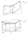
- FIGS. 1A . 1B and 1C 14 show perspective views of an embodiment of a packaging device 10 according to the invention, each with variously inserted, substantially flat, articles 12, 12 'and 12 "to be packaged,
- the packaging device 10 comprises a rectangular bottom plate 14 having a first side edge 42 and a first side edge 42
- the first cover plate 20 is pivotally connected along its first side edge 46 by means of a fold on the first side edge 42 of the bottom plate 14 and integrally
- the second cover plate 30 is hinged along its first side edge 48 by means of a fold to the second side edge 44 of the bottom plate and integrally connected to the bottom plate 14.
- a cushion layer extends continuously
- the padding layer thus comprises three subregions 22, 16 and 32 which comprise the padding layer 22 of the first cover plate 20, the padding layer 16 of the bottom plate 14 and the padding layer 32 of the second Form cover plate 30.
- the cushioning layer has a length which is substantially equal to the sum of the partial lengths of the regions on the first cover plate 20, the bottom plate 14 and the second cover plate 30.
- a width of the cushioning layer is smaller than the width of the bottom plate 14 and the first and second cover plate 20, 30, so that on both sides of the above the first cover plate 20, the bottom plate 14 and the second cover plate 30 extending cushion layer on the plates one in each case Side strips 24 and 34 is formed, which is not covered by the cushion layer.
- a closure device On a respective side strip 24 or 34 of a respective cover plate, a closure device is provided by means of which a respective cover plate can be fixed in the closed position and released again.
- the closure device is, for example, a hook-and-loop fastener device or an adhesion closure, wherein the side strips 24 and 34 of the first and second cover plates 20 and 30 respectively are the counterpart of the closure device on the side strip 18 of the bottom plate is arranged.
- a hook-and-loop fastener for example, the loop-like closure elements and on the side strips 24 and 34 the hook-like closure devices are arranged on the side strip 18, or vice versa.
- an adhesion closure the adhesive layer is provided on the side strips 24 or 34 and the corresponding prepared non-adhesive layer is provided on the side strip 18, or vice versa.
- Fig. 1A is arranged on the bottom plate 18, a relatively large substantially flat object 12.
- Fig. 1B is on the bottom plate 14 a in comparison to the in Fig. 1A shown item smaller substantially flat object 12 'stored.
- Fig. 1C are two objects 12 "arranged side by side on the bottom plate 14, wherein a respective cover plate 20 and 30 in the closed state, the corresponding object 12" completely covered.
- a pocket for receiving, in particular pushing in and out of the article is formed on the bottom plate a pocket for receiving, in particular pushing in and out of the article.
- a pocket 50 is formed by three closed sides and an open side extending along the side strip 18 of the bottom panel 14 for loading with the article 12 Fig. 1B
- a pocket 50 'for receiving the object 12' is formed on the bottom plate 14 .
- the bag 50 ' may be used alone or in addition to at least one other bag, such as the one shown in FIG Fig. 1B shown pocket 50 and / or other pockets (not shown) may be formed on the bottom plate 14.
- a respective pocket has two opposed, closed side edges and additionally a third, the two closed side edges connecting, third closed side edge, such as for the pocket 50 in Fig. 1A and the pockets 50 and 50 'in Fig. 1B shown.
- a respective pocket has a flap on an open side, such as the in Fig. 1B shown folding envelope 51 of the bag 50, which can additionally serve as a folding envelope for the pocket 50 '.
- a respective folding envelope can be pivoted into a closing and an opening position. In this case, in the opening position, the side of a bag for pushing in or out of the object Approved. In the closing position, the closed by the folding envelope side of the bag is closed, thus preventing slipping out of an inserted in the bag item from the bag.
- pockets in particular with flap closures, can also be provided on one or both cover plates.
- the device 10 has a pocket 52 with an envelope flap 53 and on the second cover plate 30 a pocket 54 with an envelope flap 55.
- the packaging device is suitable for packaging a variable size article (as shown in FIGS Figures 1A and 1B shown), or of two objects (as in Fig. 1C shown), or even three or more objects (not shown), as long as the objects on the bottom plate 18 can be arranged side by side.
- Fig. 2 shows a perspective view of a packaging device 10 with a bottom plate 14 and a cover plate 20 which is hinged with its first side edge 46 on a side edge 42 of the bottom plate 14 pivotally.
- the first cover plate 20 and the bottom plate 14 have a substantially equal width measured along the side edges 42 and 46, respectively.
- the length of the cover plate 20, the in Fig. 2 is indicated by the dimension "I", is preferably substantially equal to a length of the bottom plate 14, which in Fig. 2 indicated by the dimension "L".
- the length of the cover plate 20 may also be shorter than the length of the bottom plate 14, so that when the cover plate 20 is in the closed position, on the bottom plate 14, a strip-shaped portion (not shown) is formed extending along the side edge 44 of the bottom plate extends and which is not covered by the cover plate 20.
- carrying devices or an engaging device such as a recess 60, as in FIG Fig. 6A shown to be provided.
- Fig. 3 shows a packaging device 10 according to the invention with a bottom plate 14 and two cover plates, namely a first cover plate 20 and a second cover plate 30.
- the first cover plate 20 is hinged along its first side edge 46 at a first side edge 42 of the bottom plate 14 pivotally.
- the second cover plate 30 is hinged along its first side edge 48 at the first side edge 42 opposite the second side edge 44 of the bottom plate 14 pivotally.
- the first and second cover plates 20 and 30 respectively have a width measured along their respective side edges 46 and 48 which is substantially equal to the width of the bottom plate 14 measured along the side edges 42 and 44 of the bottom plate, respectively.
- the first and second cover plates 20 and 30, respectively, have a length I 1 and I 2 , respectively, taken together preferably corresponding to an overall length of the bottom plate 14 such that when the first and second side plates 20 and 30 are in their closed positions, the Base plate 14 is substantially completely covered by the cover plates 20 and 30.
- first and second cover plates 20 and 30 substantially completely cover the bottom plate 14, then an article 12 or 12 'inserted into the packaging device 10 may also extend beyond a portion covered by a single cover plate, as in FIGS Figures 1A and 1B are almost completely enveloped by the first and second cover plates 20 and 30 when the sum of the lengths I 1 and I 2 of the first and second cover plates is substantially equal to the length L of the bottom plate 14, as in FIG Fig. 3 shown.
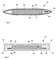
- FIGS. 4 and 5 show cross sections through a packaging device 10 in the closed state, wherein in each case an object 12 is inserted in the packaging device 10.
- the first cover plate 20 is hinged by means of a fold 70 and the second cover plate 30 by means of a fold 70 'pivotally.
- the bottom plate 14 and the first and second cover plates 20 and 30 each have an elastic bendability.
- the cushion layer is formed by an air cushion layer 66 with a plurality of air bubbles or air bubbles.
- the cushion layer presses a little, while the cushion layer in the region in which the object 12 does not extend in a relaxed, less or not pressed State is.
- the cushioning layer is pressed in the regions in which the article 12 extends, the article 12 is held non-slip with respect to a lateral displacement relative to the plates 14, 20 and 30, respectively.
- the first cover plate 20 by means of two folds, namely a first fold 72 and a second fold 74 and, accordingly, the second cover plate 30 by means of two folds, namely a first fold 72 'and a second fold 74', on the Base plate 14 hinged pivotally.
- the respective first and second folds 72 and 74 or 72 'and 74' are arranged parallel to each other and at a predetermined distance.
- the distance between the first and second folds 72 and 74 or 72 'and 74' corresponds substantially, ie, to an accuracy corresponding to a thickness of the first and second cover plate 20 and 30, the height of the packaging device 10, if the two Cover plates 20 and 30 are in the closed position.
- the distance between the first and second folds 72 and 74 or 72 'and 74' is adapted to the thickness of an article 12 to be packaged and chosen so that the distance is almost or approximately equal to the sum of the thickness of the base plate 14 with cushion layer, the thickness of the article 12 and the thickness of the first and second cover plate 20 and 30 with a cushion layer.
- the distance between the first and second folds 72 and 74 or 72 'and 74' is not less than the sum of the thicknesses of the bottom plate 14 without cushioning layer, the thickness of the article 12 and the thickness of the first and second cover plate 20 and 30 without poster layer.
- the cushioning layers of the cover plate and / or the cushion layer of the Give ground plate yield and be pressed when an object 12 is inserted between the bottom plate and located in their respective closed position cover plates and is held non-slip by the pressing against lateral slipping.
- FIGS. 6A and 6B 5 are plan views of a packaging device 10 according to the invention, which is arranged or inserted as the uppermost in a stack of packaging devices between side walls 68, 68 'and 68 "between the side walls 68, 68' and 68" is one or a plurality of Packaging devices stacked one above the other and secured against falling stack.
- a recess 60 or 60 ' is formed in a side edge of the packaging device 10.
- the recess 60 is formed in a side edge 43 of the bottom plate of the packaging apparatus 10 and congruent thereto in a side edge 47 of the cover plate.
- the recess 60 or 60 ' is used as intervention aid and allows, for example, with the fingers of a user's hand or with a gripping tool between the packaging device 10 and a side wall 68, 68' intervened and so the packaging device can be easily taken and lifted ,
- the packaging device 10 comprises recesses 62 and 62 ', respectively, formed on two diagonally opposite corners.
- the formed at the corners recesses 62 and 62 ' serve the same purpose as those formed in the side edges and in Fig. 6A shown recesses 60 and 60 '.
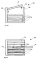
- FIGS. 7A and 7B 15 are cross-sectional views showing various embodiments of a packaging system 100 for receiving, storing, and transporting one or a plurality of packaging devices 10, 10 ', 10 "according to the invention.
- the packaging system 100 comprises a pick-up device 104 for receiving a plurality of packaging devices 10 ', wherein the pick-up device 104 is formed as a chest 108.
- the chest 108 is open at its top 106. Through the open top can a packaging device 10 'are inserted into the chest 108 as in Fig. 7A shown by the downward arrows.
- a plurality of packaging devices 10 ' may be stacked one on top of the other.
- the opening at the top 106 of the chest 108 can be closed with a lid (not shown).
- the lid may be formed as a loose part or as one or more hinged flaps pivotally hinged to the chest 108.
- the packaging system 100 includes an insertion device 114 having a plurality of insertion rails 120 as a pick-up device for receiving a plurality of packaging devices 10 ".
- the insertion device 114 has an open side 118 for loading the insertion device with packaging devices 10".
- the slide rails 120 are each provided in pairs and are arranged and configured such that a packaging device 10 "can be displaceably mounted thereon or in between, in particular inserted into the insertion device 114, as in FIG Fig. 7B in the insertion device 114, a plurality of packaging devices 10 'can be arranged one above the other and each supported by a pair of slide rails 120.
- the open side 118 of the insertion device 114 can be closed, for example by means of a or two hinged side doors (not shown) or by means of a sliding device according to the principle of a roller shutter (not shown).
Description
Die vorliegende Erfindung betrifft eine Verpackungsvorrichtung und ein Verpackungssystem für im Wesentlichen flache Gegenstände, insbesondere wertvolle und schützenswerte technische Gegenstände, wie beispielsweise Lithium-lonen-Zellen.The present invention relates to a packaging device and a packaging system for substantially flat objects, in particular valuable technical articles to be protected, such as, for example, lithium ion cells.
Zum Verpacken eines technischen Gegenstands wird dieser in herkömmlicher Weise in vielen Fällen zunächst in einer Kunststofffolie bzw. -tüte verpackt bzw. umhüllt und so vor Staub und Feuchtigkeit geschützt. Dann wird der so verpackte bzw. umhüllte Gegenstand von einer Lagerung, die in vielen Fällen aus Styropor oder aus pressgeformtem Pappmaschee ausgebildet ist, umgeben und mit bzw. in der umgebenden Lagerung in einem Umkarton verpackt. Die Lagerung dient zum stabilen Positionieren des technischen Gegenstandes innerhalb des Umkartons. Als regelmäßig geformte, in der Regel rechteckförmige Umverpackung dient der Umkarton zum nebeneinander und aufeinander Stapeln und als Transportschutz. In dem Verpackungssystem mit Kunststofffolie bzw. -tüte, Lagerung und Umkarton kann alternativ die Lagerung durch ein Verpackungsfüllmaterial, wie etwa Pappschnitzel oder Kunststoffchips, ersetzt sein. Ein Problem mit dieser herkömmlichen Verpackung ist, dass sie in vielen Fällen als Einwegverpackung behandelt und nach einmaliger Benutzung entsorgt wird. Ein weiteres Problem ist die Vielfalt der verschiedenen verwendeten Materialien, die nach der Benutzung, nach Materialart getrennt in den Müllrecyclingkreislauf zu geben sind. Wenn sie nach einer Benutzung, d.h. normalerweise einem Transport des technischen Gegenstands für eine weitere Benutzung aufbewahrt werden, stellt das relativ große Außenvolumen der Verpackung, das größer als das Volumen des darin zu verpackenden Gegenstandes ist, ein weiteres Problem dar.For packaging a technical object, it is conventionally in many cases initially wrapped or wrapped in a plastic film or bag and thus protected from dust and moisture. Then, the thus wrapped article is surrounded by a storage, which is formed in many cases of Styrofoam or molded Pappmaschee, and packed with or in the surrounding storage in a carton. The storage is used for stable positioning of the technical object within the outer carton. As a regularly shaped, usually rectangular outer packaging of the outer carton serves for juxtaposing and stacking and transport protection. In the packaging system with plastic film or bag, storage and outer carton, alternatively, the storage may be replaced by a packaging filling material, such as cardboard chips or plastic chips. A problem with this conventional packaging is that in many cases it is treated as a disposable packaging and disposed of after a single use. Another problem is the variety of different materials used, which are to be given after use, separated by material type in the waste recycling cycle. When stored after use, ie normally transport of the technical article for further use, the relatively large outer volume of the package, which is larger than the volume of the article to be packaged therein, presents another problem.
Für die Lagerung und den Transport von Gegenständen, wie etwa technischen Geräten, die an festen Verwendungsorten in großen Stückzahlen bzw. wiederholt benutzt bzw. verbaut werden, wie das etwa für Lithium-Ionen-Zellen der Fall ist, werden in manchen Fällen Mehrfachverpackungen, sogenannte Trays, verwendet. Diese Mehrfachverpackungen, insbesondere Trays, sind wiederverwendbar und können eine Vielzahl von gleichartigen Gegenständen aufnehmen. Dazu können die Mehrfachverpackungen Halterungen bzw. Einsetzformen aufweisen, die an die Form eines aufzunehmenden Gegenstands abgestimmt sind. Derartige Mehrfachverpackungen benötigen nachteilig in vielen Fällen als Staubschutz und für ein leichteres Handling bzw. leichte Stapelbarkeit eine regelmäßig geformte, beispielsweise rechteckförmige Umverpackung.For the storage and transport of articles, such as technical devices, which are used in fixed places of use in large quantities or repeatedly used, as is the case for lithium-ion cells, in some cases, multiple packaging, so-called Trays, used. These multiple packages, especially trays, are reusable and can accommodate a variety of similar items. For this purpose, the multi-packs can have holders or insert molds which are matched to the shape of an item to be picked up. Such multiple packaging disadvantageously require in many cases as a dust cover and for easier handling or easy stackability a regularly shaped, for example, rectangular outer packaging.
In
Angesicht der Probleme und Nachteile der bekannten Verpackungen und Verpackungssysteme ist es eine Aufgabe, ein technisch automatisiert zu be- und entfüllendes variables Mehrwegverpackungssystem für Produktfamilien von im Wesentlichen flachen Gegenständen, wie beispielsweise Lithium-Ionen-Zellen, bereitzustellen.In view of the problems and disadvantages of the known packaging and packaging systems, it is an object to provide a technically automated loading and unloading variable reusable packaging system for product families of substantially flat articles, such as lithium-ion cells.
Zur Lösung der Aufgabe wird wie im folgenden ausführlich beschrieben eine einfaltbare Verpackungsvorrichtung nach Anspruch 1 bereitgestellt.To solve the problem, a foldable packaging apparatus according to claim 1 is provided as described in detail below.
Wie beansprucht, wird eine Verpackungsvorrichtung bereitgestellt zum Verpacken von mindestens einem im Wesentlichen flachen Gegenstand, insbesondere einem wertvollen technischen Gegenstand, wie beispielsweise eine Lithium-Ionen-Zelle. Unter dem Begriff Verpacken ist hierin auch ein Aufnehmen bzw. Umhüllen des Gegenstands zu verstehen. Der flache Gegenstand kann insbesondere in horizontal liegender Position in der Verpackungsvorrichtung verpackt bzw. angeordnet sein.As claimed, a packaging apparatus is provided for packaging at least one substantially flat article, particularly a valuable engineering article, such as a lithium-ion cell. The term packaging is also to be understood here as the wrapping or wrapping of the article. The flat article may be packaged or arranged in particular in a horizontal position in the packaging device.
Die Verpackungsvorrichtung umfasst eine Bodenplatte mit mindestens einem ersten zumindest abschnittsweise geradlinigen Seitenrand und mindestens eine erste Abdeckplatte mit mindestens einem ersten, zumindest abschnittsweise geradlinigen Seitenrand, der an den ersten Seitenrand der Bodenplatte schwenkbar angelenkt ist. So kann die Abdeckplatte zwischen einer geschlossenen Position, in der die Abdeckplatte die Bodenplatte zumindest teilweise überdeckt, und einer geöffneten Position, in der die Abdeckplatte der Bodenplatte nicht gegenüberliegt, geschwenkt werden.The packaging device comprises a bottom plate with at least one first at least partially rectilinear side edge and at least one first cover plate with at least one first, at least partially rectilinear side edge, which hinged to the first side edge of the bottom plate pivotally is. Thus, the cover plate between a closed position in which the cover plate at least partially covers the bottom plate, and an open position in which the cover plate of the bottom plate is not opposite, are pivoted.
Erfindungsgemäß weist die Bodenplatte bzw. die mindestens eine Abdeckplatte an einer Seite eine Polsterschicht auf. Dabei ist die gepolsterte Seite dem Gegenstand zugewandt, wenn der Gegenstand in der Verpackung und die mindestens eine Abdeckplatte in ihrer geschlossenen Position ist. Ferner ist die Polsterschicht so ausgebildet, dass der Gegenstand in Bezug auf eine laterale Verschiebung rutschfest gehalten wird, wenn die mindestens eine Abdeckplatte in der geschlossenen Position ist und zumindest ein Teilbereich des Gegenstands zwischen der Abdeckplatte und der Bodenplatte angeordnet ist.According to the invention, the bottom plate or the at least one cover plate has a padding layer on one side. The padded side faces the article when the article is in the package and the at least one cover is in its closed position. Further, the cushioning layer is formed so that the article is slidably held in relation to a lateral displacement when the at least one cover plate is in the closed position and at least a portion of the object between the cover plate and the bottom plate is arranged.
Die Bodenplatte ist vorzugsweise so ausgebildet, dass der Gegenstand darauf sicher abgelegt werden kann. Beispielsweise ist die Bodenplatte mit einer Polsterung versehen bzw. ist hinsichtlich ihrer Abmessungen (Länge und Breite) größer als die Abmessungen (Länge und Breite) des zu verpackenden Gegenstands ausgebildet. Diese Ausbildung der Bodenplatte ermöglicht ein technisch automatisiertes Einbringen des Gegenstands in die Verpackungsvorrichtung. Die Ausbildung der Verpackungsvorrichtung mit der im Wesentlichen flachen Bodenplatte und der daran, insbesondere einteilig schwenkbar, angelenkten Abdeckplatte ermöglicht im Zusammenwirken mit dem darin zu verpackenden, im Wesentlichen flachen Gegenstand eine insgesamt flache Ausgestaltung der Verpackungsvorrichtung, eine gute Stapelbarkeit, wobei nahezu keine Verlust- bzw. Toträume entstehen und damit eine effiziente Raumausnutzung beim Stapeln zum Lagern bzw. Transportieren von einer Vielzahl von Verpackungsvorrichtungen erzielt wird.The bottom plate is preferably formed so that the article can be safely stored thereon. For example, the bottom plate is provided with a padding or is formed in terms of their dimensions (length and width) greater than the dimensions (length and width) of the article to be packaged. This design of the bottom plate allows a technically automated introduction of the article in the packaging device. The formation of the packaging device with the substantially flat base plate and the cover plate hinged thereto, in particular in one piece, allows, in cooperation with the substantially flat article to be packaged therein, an overall flat configuration of the packaging device, good stackability, with virtually no loss or shrinkage Dead spaces are created and efficient space utilization in stacking for storing and transporting a plurality of packaging devices is achieved.
Die Bodenplatte und die erste bzw. zweite Abdeckplatte sowie die darauf bereitgestellten Polsterschichten sind insbesondere im Wesentlichen eben ausgebildet. Vorzugsweise sind Die Bodenplatte und die erste bzw. zweite Abdeckplatte elastisch biegsam, so dass sie nach einer Biegeverformung federnd in ihre ursprüngliche, im Wesentlichen ebene Form zurückkehren.The bottom plate and the first or second cover plate and the cushion layers provided thereon are in particular substantially planar. Preferably, the bottom plate and the first and second cover plates are elastically flexible, so that they return resiliently to their original, substantially planar shape after a bending deformation.
Vorzugsweise ist die Abdeckplatte einteilig an der Bodenplatte angelenkt, insbesondere mittels eines Falzes. Die Polsterschicht kann in der Bodenplatte bzw. der mindestens einen Abdeckplatte integriert sein oder damit fest verbunden sein. Auf diese Weise ist die Verpackungsvorrichtung mit den genannten Komponenten als ganzes einteilig, mit anderen Worten: die Verpackungsvorrichtung weist keine losen Teile auf. Daher ist die Verpackungsvorrichtung als solche vollständig und kann problemlos mehrfach bzw. als Mehrwegverpackung benutzt werden.Preferably, the cover plate is integrally hinged to the bottom plate, in particular by means of a fold. The cushion layer may be integrated in the bottom plate or the at least one cover plate or be firmly connected thereto. In this way, the packaging device is integral with said components as a whole, in other words, the packaging device has no loose parts. Therefore, the packaging device as such is complete and can easily be used multiple times or as reusable packaging.
Durch die schwenkbare Anlenkung der Abdeckplatte an der Bodenplatte kann ein in der Verpackungsvorrichtung auf der Bodenplatte angeordneter Gegenstand zumindest teilweise zwischen der Bodenplatte und der Abdeckplatte aufgenommen sowie von der Bodenplatte und der Abdeckplatte umhüllt werden, wenn die Abdeckplatte in der geschlossenen Position ist: Dies ermöglicht einen guten Schutz, insbesondere einen Rundumschutz, für den verpackten Gegenstand.Due to the pivotable articulation of the cover plate on the bottom plate arranged in the packaging device on the bottom plate object at least partially received between the bottom plate and the cover plate and are enveloped by the bottom plate and the cover plate when the cover plate is in the closed position: This allows one good protection, in particular all-round protection, for the packaged item.
Aufgrund der insgesamt flachen Ausgestaltung der Verpackungsvorrichtung in Sandwichbauweise, d.h. Bodenplatte - flacher Gegenstand - Abdeckplatte, eignet sich die Verpackungsvorrichtung insbesondere für Anwendungen, bei denen die Bodenplatte im Wesentlichen in horizontaler Position angeordnet ist, wenn die Verpackungsvorrichtung mit dem technischen Gegenstand befüllt bzw. gelagert wird, insbesondere wenn die Verpackungsvorrichtung in einer vertikalen Stapelanordnungen einer Vielzahl von Verpackungsvorrichtungen gelagert wird.Due to the overall flat configuration of the sandwich packaging apparatus, i. Bottom plate - flat object - cover plate, the packaging device is particularly suitable for applications in which the bottom plate is arranged substantially in a horizontal position when the packaging device is filled with the technical object, in particular when the packaging device in a vertical stacking arrangements of a plurality is stored by packaging devices.
Für eine sichere bzw. rundum schütztende Verpackung des Gegenstandes genügt es, dass die Abdeckplatte in der geschlossenen Position die Bodenplatte nur teilweise, d.h. in einem Teilbereich überdeckt, wobei der Gegenstand in diesem Teilbereich Platz findet. Vorzugsweise jedoch überdeckt die Abdeckplatte in ihrer geschlossenen Position die Bodenplatte nahezu vollständig, so dass im Wesentlichen die gesamte Fläche der Bodenplatte zum Ablegen von einem oder mehreren zu verpackenden Gegenständen zur Verfügung steht.For a secure or all-round protective packaging of the article, it is sufficient that the cover plate in the closed position, the base plate only partially, i. covered in a sub-area, the object finds room in this sub-area. Preferably, however, the cover plate in its closed position covers the bottom plate almost completely, so that substantially the entire surface of the bottom plate is available for depositing one or more objects to be packaged.
In einer Ausgestaltung kann die Verpackungsvorrichtung eine zweite obere Abdeckplatte mit einem ersten zumindest abschnittweise geradlinigen Seitenrand aufweisen, wobei der erste Seitenrand der zweiten Abdeckplatte an einem dem ersten Seitenrand der Bodenplatte gegenüberliegenden, zweiten, zumindest abschnittweise geradlinigen Seitenrand der Bodenplatte schwenkbar angelenkt ist, so dass die zweite Abdeckplatte zwischen einer geschlossenen Position, in der die zweite Abdeckplatte der Bodenplatte zumindest teilweise überdeckt, und einer geöffneten Position, in der die zweite Abdeckplatte der Bodenplatte nicht gegenüberliegt, geschwenkt werden kann. Vorzugsweise weist die zweite Abdeckplatte an einer Seite eine Polsterschicht auf, wobei die gepolsterte Seite dem Gegenstand zugewandt ist, wenn der Gegenstand in der Verpackung und die zweite Abdeckplatte in der geschlossenen Position ist. Wie das auch mit der ersten Abdeckplatte der Fall ist, kann der Gegenstand in Bezug auf eine laterale Verschiebung rutschfest gehalten werden, wenn die zweite Abdeckplatte in der geschlossenen Position ist und zumindest ein Teilbereich des Gegenstands zwischen der zweiten Abdeckplatte und der Bodenplatte der Verpackungsvorrichtung angeordnet ist.In one embodiment, the packaging device may have a second upper cover plate with a first at least partially rectilinear side edge, wherein the first side edge of the second cover plate at one of the first Side edge of the bottom plate opposite, second, at least partially rectilinear side edge of the bottom plate is pivotally hinged, so that the second cover plate between a closed position in which the second cover plate of the bottom plate at least partially covers, and an open position in which the second cover plate of the bottom plate not opposite, can be pivoted. Preferably, the second cover plate has a cushioning layer on one side, the cushioned side facing the article when the article is in the package and the second cover plate is in the closed position. As with the first cover plate, the article may be slidably held in relation to lateral displacement when the second cover plate is in the closed position and at least a portion of the article is disposed between the second cover plate and the bottom plate of the packaging device ,
Mit der zweiten Abdeckplatte wird es unter anderem möglich, dass in der Verpackungsvorrichtung zwei im Wesentlichen flache technische Gegenstände unabhängig voneinander verpackt werden, wobei der eine Gegenstand zumindest in einem Teilbereich des Gegenstands zwischen der Bodenplatte und der ersten Abdeckplatte rutschfest gehalten und der zweite Gegenstand zumindest in einem Teilbereich zwischen der Bodenplatte und der zweiten Abdeckplatte rutschfest gehalten wird.The second cover plate makes it possible, inter alia, for two substantially flat technical articles to be packed independently in the packaging device, wherein the article is held non-slip at least in a partial area of the article between the bottom plate and the first cover plate and the second article is at least held in place a portion between the bottom plate and the second cover plate is held non-slip.
Mit der zweiten Abdeckplatte, die zusätzlich zur ersten Abdeckplatte bereitgestellt ist, ist es auch möglich, einen relativ großen technischen Gegenstand zwischen der Bodenplatte einerseits und der ersten und zweiten Abdeckplatte andererseits aufzunehmen und rutschfest zu positionieren. Dazu sind vorzugsweise die erste Abdeckplatte und die zweite Abdeckplatte so ausgebildet, dass sie zusammen einen in der Verpackung aufgenommenen Gegenstand im Wesentlichen vollständig überdecken und insbesondere zusammen die Bodenplatte nahezu vollständig überdecken, wenn die erste und zweite Abdeckplatte jeweils in ihrer geschlossenen Position sind.With the second cover plate, which is provided in addition to the first cover plate, it is also possible to accommodate a relatively large technical object between the bottom plate on the one hand and the first and second cover plate on the other hand and to position it non-slip. For this purpose, preferably the first cover plate and the second cover plate are formed so that they substantially completely cover an object received in the package and in particular almost completely cover the bottom plate together when the first and second cover plate are each in their closed position.
Zur Ausbildung der in Bezug auf eine laterale Verschiebung rutschfesten Halterung kann der Gegenstand in der Verpackung zwischen der auf einer Abdeckplatte angeordneten Polsterschicht und der auf der Bodenplatte angeordneten Polsterschicht in einer Klemmhaltung gehalten sein. Die mindestens eine Abdeckplatte bzw. die Bodenplatte können biegsam, insbesondere federnd bzw. elastisch biegsam sein. So kann beim Anordnen des Gegenstands zwischen der Boden- und der Abdeckplatte, wenn die mindestens eine Abdeckplatte in ihrer geschlossenen Position ist, durch die elastische Rückstellkraft der Platte bzw. der Platten eine die Klemmung bewirkende Druckkraft erzeugt werden.In order to form the non-slip support with respect to a lateral displacement, the article in the package may be held in a clamping position between the cushion layer disposed on a cover plate and the cushion layer disposed on the bottom plate. The at least one cover plate or the Base plate can be flexible, in particular resilient or flexible elastic. Thus, in arranging the object between the bottom and the cover plate, when the at least one cover plate is in its closed position, a compressive force causing the clamping can be generated by the elastic restoring force of the plate or plates.
Zur Verbesserung der Rutschfestigkeit weist die Polsterschicht eine auf einer Seite angeordnete Anti-Rutsch-Beschichtung auf. Dabei ist die beschichtete Seite dem Gegenstand zugewandt, wenn der Gegenstand in der Verpackung aufgenommen und die mindestens eine Abdeckplatte in der geschlossenen Position ist. Die Anti-Rutsch-Beschichtung kann aus einem gummiartigen Material ausgebildet sein. Sie kann auch durch Aufbringen einer die Haftreibung vergrößernden Beschichtung auf die Polsterschicht ausgebildet werden. Insbesondere kann die Anti-Rutsch-Beschichtung eine adhäsive Schicht aufweisen zum lösbaren Fixieren des Gegenstands, wenn dieser zumindest in einem Teilbereich mit der Schicht in Kontakt ist.To improve slip resistance, the cushion layer has a one-sided anti-skid coating. The coated side faces the article when the article is received in the package and the at least one cover plate is in the closed position. The anti-slip coating may be formed of a rubbery material. It can also be formed by applying a friction-enhancing coating to the cushion layer. In particular, the anti-slip coating may have an adhesive layer for releasably fixing the article when it is in contact with the layer at least in a partial area.
Die in Bezug auf eine laterale Verschiebung rutschfeste Halterung kann auch dadurch erzielt werden, dass auf der Polsterschicht der Bodenplatte und/oder auf der Polsterschicht von mindestens einer Abdeckplatte eine Tasche zum Aufnehmen, insbesondere zum leichten Hineinschieben und Herausziehen des Gegenstands, ausgebildet ist. Die Tasche kann an zwei gegenüberliegenden Seiten geschlossen sein. An einer dritten, die gegenüberliegende Seite verbindenden Seite kann die Tasche ebenfalls geschlossen sein oder es kann dort alternativ ein Klappverschluss angeordnet sein. An einer vierten, offenen, die beiden geschlossenen Seiten ebenfalls verbindenden Seite ist vorzugsweise ein Klappverschluss ausgebildet. Wenn der Gegenstand in die Tasche hineingeschoben ist, ist dieser durch die Tasche in Bezug auf eine laterale Verschiebung fixiert, insbesondere bezüglich einer Verschiebung in Richtung auf die geschlossenen Seiten der Tasche und ggf. in Richtung auf die mittels Klappverschluss verschlossenen Seiten der Tasche.The non-slip support in relation to a lateral displacement can also be achieved by forming on the cushion layer of the bottom plate and / or on the cushion layer of at least one cover plate a pocket for receiving, in particular for pushing in and pulling out the object. The bag can be closed on two opposite sides. At a third, the opposite side connecting side, the bag may also be closed or it may alternatively be arranged a snap closure. At a fourth, open, the two closed sides also connecting side preferably a snap closure is formed. When the article is pushed into the pocket, it is fixed by the pocket with respect to a lateral displacement, in particular with respect to a displacement towards the closed sides of the pocket and possibly towards the flap-closed sides of the pocket.
Die erste Abdeckplatte, gegebenenfalls eine zweite Abdeckplatte und die Bodenplatte können jeweils mindestens eine an mindestens einem Seitenrand der jeweiligen Platte ausgebildete Ausnehmung aufweisen. Vorzugsweise ist die mindestens eine Ausnehmung in der Bodenplatte im Wesentlichen kongruent zu einer entsprechenden Ausnehmung in der ersten bzw. zweiten Abdeckplatte, wenn die erste bzw. zweite Abdeckplatte in ihrer geschlossenen Position sind. Mindestens eine Ausnehmung in der Bodenplatte kann an einer Ecke der Bodenplatte ausgebildet sein. Die Bodenplatte kann auch zwei an einander diagonal gegenüberliegenden Ecken ausgebildete Ausnehmung aufweisen. Kongruent zu der einen bzw. der mehreren Ausnehmungen in der Bodenplatte kann die erste bzw. zweite Abdeckplatte entsprechend angeordnete Ausnehmungen aufweisen. Die Ausnehmungen dienen dazu, dass eine liegend angeordnete Verpackungsvorrichtung, insbesondere wenn sie zwischen seitlichen Wänden angeordnet ist, durch Eingreifen eines Werkzeugs bzw. Eingreifen mit den Fingern einer Hand eines Benutzers leicht aufgenommen und hochgehoben werden kann.The first cover plate, optionally a second cover plate and the bottom plate may each have at least one recess formed on at least one side edge of the respective plate. Preferably, the at least one recess in the bottom plate is substantially congruent with a corresponding recess in the first and second cover plates, respectively, when the first and second cover plates are in their closed position. At least one recess in the bottom plate may be formed at a corner of the bottom plate. The bottom plate can also have two recesses formed at diagonally opposite corners. Congruent to the one or more recesses in the bottom plate, the first and second cover plate having correspondingly arranged recesses. The recesses serve to allow a lying packaging device, especially if it is arranged between lateral walls, to be easily picked up and lifted by engaging a tool or the fingers of a user's hand.
Die Polsterschicht kann aus einem weichen Material ausgebildet sein, das integral an der Bodenplatte bzw. der Abdeckplatte ausgebildet oder auf die Bodenplatte bzw. Abdeckplatte aufgebracht ist. Insbesondere kann eine, insbesondere jeweilige, Polsterschicht als Luftpolsterfolienschicht ausgebildet sein. So wird der Gegenstand beim Auflegen auf die gepolsterte Bodenplatte federnd aufgenommen und ohne Risiko eines Verkratzens und gegen mechanische Stöße von außen geschützt in der Verpackungsvorrichtung aufgenommen.The cushioning layer may be formed of a soft material that is integrally formed on the bottom plate or the cover plate or applied to the bottom plate or cover plate. In particular, one, in particular respective, cushion layer may be formed as an air cushion film layer. Thus, the article is resiliently received when placed on the padded base plate and protected without risk of scratching and against mechanical shock from the outside in the packaging device.
Die mindestens eine Abdeckplatte kann durch einen Falz bzw. Falze einteilig mit der Bodenplatte verbunden und auf diese Weise schwenkbar angelenkt sein. Wenn ein einziger Falz vorgesehen ist und wenn die mindestens eine Abdeckplatte in die geschlossene Position gebracht wird, wobei zwischen der Abdeckplatte und der Bodenplatte der zu verpackende Gegenstand eingelegt ist, dann drückt sich der Gegenstand aufgrund seiner endlichen Dicke in die Polsterschicht auf der Bodenplatte und/oder die Polsterschicht der Abdeckplatte ein und wird auf diese Weise fixiert. Ein jeweiliger Falz ist vorzugsweise so ausgebildet, dass die Abdeckplatte in Bezug auf die Bodenplatte aus der geschlossenen Position um einen Winkel von mindestens 90 Grad, vorzugsweise 135 Grad und noch mehr bevorzugt mindestens 180 Grad in eine geöffnete Position geschwenkt werden kann.The at least one cover plate can be integrally connected by a fold or folds with the bottom plate and hinged in this way pivotally. If a single fold is provided and if the at least one cover plate is brought into the closed position, wherein between the cover plate and the bottom plate of the object to be packaged, then the article presses due to its finite thickness in the cushion layer on the bottom plate and / or the cushion layer of the cover plate and is fixed in this way. A respective fold is preferably formed so that the cover plate with respect to the bottom plate from the closed position by an angle of at least 90 degrees, preferably 135 degrees and even more preferably at least 180 degrees can be pivoted to an open position.
Alternativ zu der einen Falzung kann die mindestens eine Abdeckplatte mittels zwei in einem vorbestimmten Abstand angeordneten Falzungen einteilig mit der Bodenplatte verbunden sein. Dabei kann insbesondere der Abstand der beiden Falzungen so gewählt werden, dass er mit einer Genauigkeit, die im Wesentlichen einer Dicke der Bodenplatte bzw. der Abdeckplatte entspricht, der Höhe der Verpackung entspricht, wenn die Abdeckplatte in ihrer geschlossenen Position ist.As an alternative to the one fold, the at least one cover plate can be integrally connected to the bottom plate by means of two folds arranged at a predetermined spacing. In this case, in particular, the distance of the two folds can be selected so that it corresponds to the height of the packaging with an accuracy which substantially corresponds to a thickness of the bottom plate or the cover plate when the cover plate is in its closed position.
Insbesondere kann jede der beiden Falzungen so ausgebildet sein, dass die Abdeckplatte in Bezug auf die Bodenplatte um einen Winkel von mindestens 45 Grad, vorzugsweise 60 Grad und noch bevorzugter mindestens 90 Grad schwenkbar geöffnet werden kann, wenn die Abdeckplatte in Bezug auf die Bodenplatte aus ihrer geschlossenen Position in eine geöffnete Position geschwenkt wird. Wenn die Abdeckplatte in ihrer geschlossenen Position ist, kann der Bereich zwischen den beiden Falzungen eine Seitenwand der Verpackungsvorrichtung ausbilden. Durch Ausbilden von zwei Falzungen kann die Verpackungsvorrichtung zum Verpacken bzw. Aufnehmen auch eines relativ dicken Gegenstands angepasst werden, insbesondere ohne dass dabei die Bodenplatte und/oder die mindestens eine Abdeckplatte einer starken Biegung unterliegen.In particular, each of the two folds may be configured such that the cover plate can be pivotally opened with respect to the bottom plate by an angle of at least 45 degrees, preferably 60 degrees and more preferably at least 90 degrees, when the cover plate is out of its relative to the bottom plate pivoted closed position in an open position. When the cover plate is in its closed position, the area between the two folds can form a side wall of the packaging device. By forming two folds, the packaging device can also be adapted for packaging or picking up a relatively thick object, in particular without the bottom plate and / or the at least one cover plate being subjected to a strong bend.
Die Verpackungsvorrichtung kann so ausgebildet sein, dass wenn eine jeweilige Abdeckplatte in ihrer geschlossenen Position ist, ein zwischen der jeweiligen Abdeckplatte und der Bodenplatte ausgebildeter, umhüllter Zwischenraum bzw. ein darin aufgenommener Gegenstand in Bezug auf eine Umgebung der Verpackung thermisch isoliert und/oder elektrisch isoliert ist. Insbesondere kann die Bodenplatte bzw. die mindestens eine Abdeckplatte zur thermischen Isolation eine spiegelnde Metallschicht aufweisen. Insbesondere kann die Metallschicht elektrisch isoliert angeordnet sein von der Seite der Polsterschicht, die dem Gegenstand zugewandt ist, wenn der Gegenstand in der Verpackung aufgenommen und die mindestens eine Abdeckplatte in der geschlossenen Position ist. Zur elektrischen Isolierung kann die Polsterschicht selbst aus einer elektrisch isolierenden Schicht, insbesondere Kunststoffschicht, ausgebildet sein. Alternativ oder zusätzlich dazu kann zusätzlich zur Polsterschicht eine elektrisch isolierende Schicht in der Verpackungsvorrichtung so integriert sein, dass die elektrisch isolierende Schicht einen in der Verpackungsvorrichtung eingelegten Gegenstand vollständig umhüllt, wenn die mindestens eine Abdeckschicht bzw. die Abdeckschichten in ihrer geschlossenen Position sind.The packaging device may be configured such that when a respective cover plate is in its closed position, a wrapped space formed between the respective cover plate and the bottom plate is thermally insulated and / or electrically insulated with respect to an environment of the packaging is. In particular, the bottom plate or the at least one cover plate for thermal insulation may comprise a reflective metal layer. In particular, the metal layer may be electrically insulated from the side of the cushioning layer facing the article when the article is received in the package and the at least one cover plate is in the closed position. For electrical insulation, the padding layer itself can be formed from an electrically insulating layer, in particular a plastic layer. Alternatively or additionally, in addition to Padding layer may be an electrically insulating layer in the packaging device integrated so that the electrically insulating layer completely envelopes an inserted in the packaging device object when the at least one cover layer and the cover layers are in their closed position.
Die Verpackungsvorrichtung kann zusätzlich einen RFID-Transponder mit einer damit verbundenen Speichereinrichtung aufweisen. Die Speichereinrichtung kann so ausgebildet sein, dass darin Daten mit Informationen, wie etwa logistische, technische bzw. materialwirtschaftliche Informationen abgespeichert werden können oder darin abgespeichert sind. Logistische Information können beispielsweise den Herstellungsort und das Herstellungsdatum des Gegenstands, den Auslieferungsort und die Auslieferungsadresse des Gegenstands und technische Informationen über den Gegenstand, wie etwa eine Typbezeichnung, Typnummer, Seriennummer bzw. Prüfnummer, technische Daten und dergleichen umfassen. Materialwirtschaftliche Informationen können beispielsweise die Stückzahl der in der Verpackungsvorrichtung verpackten Gegenstände, ein Bestelldatum, ein Verpackungsdatum bzw. ein Auslieferungsdatum umfassen. Das Abspeichern derartiger Informationen in der Speichereinrichtung kann vorzugsweise beim automatisierten Befüllen der Verpackungsvorrichtung bewirkt werden. Über den RFID-Transponder, der als Empfänger bzw. Sender arbeiten kann, kann Information von einem externen Sender empfangen bzw. zu einer externen Empfangsvorrichtung gesendet werden und damit ein Daten- bzw. Informationsaustausch, insbesondere auch ein bidirektionaler Daten- bzw. Informationsaustausch, stattfinden. So kann ein Speichereinhalt der Speichereinrichtung aktualisiert werden, wenn beispielsweise ein erster bzw. ein weiterer Gegenstand in der Verpackungsvorrichtung aufgenommen wird, oder wenn ein Gegenstand aus der Verpackungsvorrichtung entnommen wird, wenn die Verpackungsvorrichtung eine räumliche Schwelle, beispielsweise ein Fabrikstor bzw. ein Lagerstättentor bzw. einen Lieferanteneingang passiert. Mittels des RFID-Transponders und der damit verbundenen Speichereinrichtung kann ein materialwirtschaftlicher Materialfluss entlang einer Materialflusskette von der Herstellung bis zur Auslieferung bzw. Benutzung automatisiert überwacht und insbesondere auch gesteuert werden.The packaging device may additionally have an RFID transponder with a storage device connected thereto. The storage device may be designed such that data with information such as logistical, technical or material-economic information can be stored therein or stored therein. Logistic information may include, for example, the manufacturing location and date of manufacture of the item, the delivery location and delivery address of the item, and technical information about the item, such as a type designation, type number, serial number, specifications, and the like. Material economic information may include, for example, the number of items packaged in the packaging device, an order date, a packaging date or a delivery date. The storage of such information in the storage device can preferably be effected during automated filling of the packaging device. About the RFID transponder, which can operate as a receiver or transmitter, information can be received from an external transmitter or sent to an external receiving device and thus a data or information exchange, especially a bidirectional data or information exchange, take place , Thus, a memory content of the memory device may be updated, for example, when a first or another object is received in the packaging device, or when an object is removed from the packaging device, when the packaging device is a spatial threshold, such as a factory gate or a Lagerstorentor or a supplier receipt happens. By means of the RFID transponder and the storage device connected thereto, a material-economical material flow along a material flow chain from production to delivery or use can be automatically monitored and in particular also controlled.
Die Verpackungsvorrichtung kann auch einen Schocksensor zum Detektieren eines mechanischen Stoßes bzw. einer auf die Verpackung einwirkenden Beschleunigung aufweisen. Insbesondere kann der Schocksensor oder eine operativ mit diesem verbundene Signalauswerteeinrichtung detektieren, dass die Beschleunigung größer als ein vorbestimmter Beschleunigungsgrenzwert ist. Die Verpackungsvorrichtung kann auch einen Temperatursensor, einen Feuchtigkeitssensor und/oder einen Sensor zum Messen eines elektrischen bzw. magnetischen Feldes aufweisen. Durch Überwachen der von diesen Sensoren (Schocksensor, Temperatursensor, usw.) erzeugten Messsignale kann nachverfolgt bzw. gezeigt werden, ob während eines bestimmten Zeitraums, beispielsweise während eines Transports, im Innern der Verpackungsvorrichtung eine hohe Belastung für den verpackten Gegenstand, beispielsweise durch einen mechanischen Schock, eine hohe Temperatur, eine hohe Luftfeuchtigkeit, ein starkes elektrisches oder magnetisches Feld, aufgetreten ist oder nicht.The packaging device may also include a shock sensor for detecting a mechanical impact or an acceleration acting on the packaging. In particular, the shock sensor or a signal evaluation device operatively connected thereto can detect that the acceleration is greater than a predetermined acceleration limit value. The packaging device may also include a temperature sensor, a humidity sensor and / or a sensor for measuring an electric or magnetic field. By monitoring the measurement signals generated by these sensors (shock sensor, temperature sensor, etc.), it can be tracked whether, during a certain period of time, for example during transport, inside the packaging device there is a high load on the packaged article, e.g. Shock, high temperature, high humidity, a strong electric or magnetic field, has occurred or not.
Der RFID-Transponder mit der Speichereinrichtung bzw. der Schocksensor bzw. ein jeweiliger anderer der vorgenannten Sensoren kann, insbesondere zusammen mit, beispielsweise neben, einem zwischen einer Abdeckplatte und der Bodenplatte aufgenommenen Gegenstand insbesondere rutschfest angeordnet sein, wenn die Abdeckplatte in ihrer geschlossenen Position ist. Alternativ oder zusätzlich dazu kann der RFID- Transponder mit der Speichereinrichtung bzw. Schocksensor bzw. Temperatursensor bzw. ein jeweiliger anderer Sensor an der Bodenplatte oder einer Abdeckplatte so befestigt sein, dass die Dicke bzw. Höhe der Verpackung an der Stelle, wo der Transponder bzw. der Sensor befestigt ist, nicht höher als die Dicke der Verpackung ist, wenn der Gegenstand in der Verpackung zwischen der Bodenplatte und einer Abdeckplatte aufgenommen ist. Beispielsweise kann der RFID-Transponder mit der Speichereinrichtung bzw. der Schocksensor bzw. der Temperatursensor bzw. ein jeweiliger anderer Sensor in einer Ausnehmung der Polsterschicht und/oder in einer Ausnehmung der Bodenplatte bzw. der Abdeckplatte angeordnet sein.The RFID transponder with the memory device or the shock sensor or a respective other of the aforementioned sensors, in particular together with, for example, in addition to a recorded between a cover plate and the bottom plate object in particular be arranged non-slip when the cover plate is in its closed position , Alternatively or additionally, the RFID transponder with the storage device or shock sensor or temperature sensor or a respective other sensor to the bottom plate or a cover plate be secured so that the thickness or height of the packaging at the point where the transponder or the sensor is mounted, not higher than the thickness of the packaging, when the article is received in the packaging between the bottom plate and a cover plate. For example, the RFID transponder with the storage device or the shock sensor or the temperature sensor or a respective other sensor may be arranged in a recess of the cushion layer and / or in a recess of the bottom plate or the cover plate.
In der Verpackungsvorrichtung kann ein Entfeuchtungsmittel, beispielsweise SilikaGel bereitgestellt sein. Das Entfeuchtungsmittel kann auf einer Seite von mindestens einer Polsterschicht bereitgestellt sein, wobei die gepolsterte Seite dem Gegenstand zugewandt ist, wenn der Gegenstand in der Verpackung und die mindestens eine Abdeckplatte in der geschlossenen Position ist. Insbesondere kann das Entfeuchtungsmittel in einer auf der Seite der Polsterschicht ausgebildeten, feuchtigkeitsdurchlässigen Tasche oder in Form von auf der Oberfläche auf der Seite der Polsterschicht aufgebrachten Partikeln bereitgestellt sein. Das Entfeuchtungsmittel nimmt Feuchtigkeit auf, und entfeuchtet so die Atmosphäre in dem Raum, in dem der Gegenstand in der Verpackungsvorrichtung aufgenommen ist, wenn die mindestens eine Abdeckplatte in der geschlossenen Position ist.A dehumidifying agent, such as silica gel, may be provided in the packaging device. The dehumidifying agent may be provided on one side of at least one cushioning layer, the cushioned side of the article facing, when the object in the package and the at least one cover plate is in the closed position. In particular, the dehumidifying agent may be provided in a moisture-permeable pocket formed on the side of the cushioning layer or in the form of particles applied to the surface on the side of the cushioning layer. The dehumidifying agent absorbs moisture and thus dehumidifies the atmosphere in the space in which the article is received in the packaging device when the at least one cover plate is in the closed position.
Nach einem weiteren Aspekt der Erfindung wird, wie beansprucht, ein Verpackungssystem bereitgestellt zum Aufnehmen und sicheren Transport einer Vielzahl von im Wesentlichen flachen Gegenständen, insbesondere wertvollen technischen Gegenständen, wie beispielsweise Lithium-lonen-Zellen. Das Verpackungssystem umfasst mindestens eine Verpackungsvorrichtung wie oben beschrieben und eine Aufnehmvorrichtung zum Aufnehmen einer Vielzahl von Verpackungsvorrichtungen wie oben beschrieben. Die Aufnehmvorrichtung ist so ausgebildet, dass eine jeweilige Verpackungsvorrichtung in die Aufnehmvorrichtung eingelegt und/oder aus dieser entnommen werden kann. Vorzugsweise ist in dem Verpackungssystem die Vielzahl der Verpackungsvorrichtungen parallel zueinander angeordnet. Mit einem derartigen Verpackungssystem kann eine Vielzahl von Verpackungsvorrichtungen unter Vermeidung größerer Verlust- bzw. Toträume, d.h. mit effektiver Raumausnutzung, gelagert bzw. transportiert werden.According to another aspect of the invention, as claimed, a packaging system is provided for receiving and securely transporting a plurality of substantially flat articles, particularly valuable engineering items, such as lithium ion cells. The packaging system comprises at least one packaging device as described above and a picking device for receiving a plurality of packaging devices as described above. The pick-up device is designed so that a respective packaging device can be inserted into the pick-up device and / or removed from it. Preferably, in the packaging system, the plurality of packaging devices are arranged parallel to each other. With such a packaging system, a plurality of packaging devices may be avoided while avoiding large dead spaces, i. with effective use of space, stored or transported.
In einer Ausführungsform des Verpackungssystems ist die Aufnehmvorrichtung eine an ihrer Oberseite im Wesentlichen offene und insbesondere verschließbare Truhe. Die Truhe ist dazu ausgebildet, dass eine jeweilige Verpackungsvorrichtung durch die offene Oberseite der Truhe in die Truhe eingelegt und aus der Truhe entnommen werden kann bzw. dass in der Truhe eine Vielzahl von Verpackungsvorrichtungen gestapelt werden kann.In one embodiment of the packaging system, the pick-up device is a chest which is essentially open on its upper side and in particular closable. The chest is designed so that a respective packaging device can be inserted through the open top of the chest into the chest and removed from the chest or that in the chest a variety of packaging devices can be stacked.
In einer anderen Ausführungsform des Verpackungssystems ist die Aufnehmvorrichtung eine an einer Seite im Wesentlichen offene und insbesondere verschließbare Einschubvorrichtung, die dazu ausgebildet ist, dass eine jeweilige Verpackungsvorrichtung durch die offene Seite, beispielsweise im Wesentlichen in horizontaler Orientierung und in horizontaler Richtung, in die Einschubvorrichtung eingeschoben und daraus herausgezogen werden kann, und dass in der Einschubvorrichtung eine Vielzahl von Verpackungsvorrichtungen übereinander, insbesondere auf Einschubschienen verschiebbar, angeordnet ist.In another embodiment of the packaging system, the pick-up device is an insertion device which is essentially open on one side and in particular closable, which is designed such that a respective packaging device passes through the open side, for example substantially in a horizontal orientation and in the horizontal direction, inserted into the insertion device and can be pulled out therefrom, and that in the insertion device a plurality of packaging devices one above the other, in particular slidably mounted on slide rails, is arranged.
Die vorliegende Erfindung wird im folgenden beispielhaft anhand bestimmter, nicht als beschränkend anzusehenden Ausführungsformen mit Verweis auf die beigefügten Zeichnungen beschrieben. In den Zeichnungen zeigen:
-
Fig. 1A ,1B und1C perspektivische Ansichten einer erfindungsgemäßen Verpackungsvorrichtung mit verschiedenartigen auf der Bodenplatte aufgelegten Gegen ständen und zwei Abdeckplatten in teilweise geöffneter Position; -
Fig. 2 eine erfindungsgemäße Verpackungsvorrichtung mit einer einzigen Abdeckplatte; -
Fig. 3 eine erfindungsgemäße Verpackungsvorrichtung mit zwei Abdeckplatten; -
Fig. 4 einen Querschnitt durch eine geschlossene Verpackungsvorrichtung nach der Erfindung mit einem eingelegten Gegenstand, wobei eine jeweilige Abdeckplatte mit einem Falz an der Bodenplatte angelenkt ist; -
Fig. 5 einen Querschnitt durch eine geschlossene Verpackungsvorrichtung nach der Erfindung mit einem in die Verpackungsvorrichtung eingelegten Gegenstand, wobei eine jeweilige Abdeckplatte mit zwei Falzen an der Bodenplatte angelenkt ist; -
Figuren 6A und 6B eine Aufsicht auf eine erfindungsgemäße Verpackungsvorrichtung, die zwischen Seitenwänden angeordnet ist zum Stabilisieren eines Stapels von Verpackungsvorrichtungen und die an mindestens einem Seitenrand ausgebildete Ausnehmungen aufweist; und -
Fig. 7A und Fig. 7B Querschnitte eines Verpackungssystems in einer ersten und zweiten Ausführungsform.
-
Fig. 1A .1B and1C perspective views of a packaging device according to the invention with various types of objects placed on the bottom plate and two cover plates in a partially open position; -
Fig. 2 a packaging device according to the invention with a single cover plate; -
Fig. 3 a packaging device according to the invention with two cover plates; -
Fig. 4 a cross-section through a closed packaging device according to the invention with an inserted object, wherein a respective cover plate is articulated with a fold on the bottom plate; -
Fig. 5 a cross-section through a closed packaging device according to the invention with an inserted into the packaging device object, wherein a respective cover plate is hinged with two folds on the bottom plate; -
Figures 6A and 6B a plan view of a packaging device according to the invention, which is arranged between side walls for stabilizing a stack of packaging devices and having formed on at least one side edge recesses; and -
FIGS. 7A and 7B Cross sections of a packaging system in a first and second embodiment.
Die
Auf einem jeweiligen Seitenstreifen 24 bzw. 34 einer jeweiligen Abdeckplatte ist eine Verschlussvorrichtung bereitgestellt, mittels der eine jeweilige Abdeckplatte in der geschlossenen Position fixiert und wieder gelöst werden kann. Die Verschlussvorrichtung ist beispielsweise eine Klettverschlussvorrichtung oder ein Adhäsionsverschluss, wobei auf den Seitenstreifen 24 bzw. 34 der ersten bzw. der zweiten Abdeckplatte 20 bzw. 30 das Gegenstück zu der Verschlussvorrichtung auf dem Seitenstreifen 18 der Bodenplatte angeordnet ist. Im Falle eines Klettverschlusses sind auf dem Seitenstreifen 18 beispielsweise die schlingenartigen Verschlusselemente und auf den Seitenstreifen 24 bzw. 34 die hakenartigen Verschlussvorrichtungen angeordnet, oder umgekehrt. Im Falle eines Adhäsionsverschlusses ist auf den Seitenstreifen 24 bzw. 34 die Adhäsionsmittelschicht und auf dem Seitenstreifen 18 die entsprechende vorbereitete nicht adhäsive Schicht bereitgestellt, oder umgekehrt.On a
In der
In der in
Eine jeweilige Tasche weist zwei gegenüberliegende, geschlossene Seitenränder auf und zusätzlich einen dritten, die beiden geschlossenen Seitenränder verbindenden, dritten geschlossenen Seitenrand auf, wie beispielsweise für die Tasche 50 in
Alternativ zu oder zusätzlich zu Taschen auf der Bodenplatte kann auch auf einer oder auf beiden Abdeckplatten Taschen, insbesondere mit Klappverschlüssen, vorgesehen sein. In
Wie in den
In
Wenn die erste und zweite Abdeckplatte 20 und 30 die Bodenplatte 14 im Wesentlichen vollständig überdecken, dann kann auch ein in die Verpackungsvorrichtung 10 eingelegter Gegenstand 12 bzw. 12', der sich über einen von einer einzigen Abdeckplatte abgedeckten Teilbereich hinaus erstreckt, wie in den
Die
Bei der in den
In der in
Die
Wie in
Die
In einer in
In der in
- 10, 10', 10"10, 10 ', 10 "
- Verpackungsvorrichtung bzw. VerpackungPackaging device or packaging
- 12, 12', 12"12, 12 ', 12 "
- Gegenstand, beispielsweise Lithium-lonen-ZelleObject, for example, lithium ion cell
- 1414
- Bodenplattebaseplate
- 1616
- Polsterschicht (auf Bodenplatte)Padding layer (on bottom plate)
- 1818
- Seitenstreifen (auf Bodenplatte)Side stripes (on bottom plate)
- 2020
- erste Abdeckplattefirst cover plate
- 2222
- Polsterschicht (auf erster Abdeckplatte)Padding layer (on first cover plate)
- 2424
- Seitenstreifen (auf erster Abdeckplatte)Side strips (on the first cover plate)
- 3030
- zweite Abdeckplattesecond cover plate
- 3232
- Polsterschicht (auf zweiter Abdeckplatte)Padding layer (on second cover plate)
- 3434
- Seitenstreifen (auf zweiter Abdeckplatte)Side strips (on second cover plate)
- 4242
- erster Seitenrand (der Bodenplatte)first margin (the bottom plate)
- 4343
- dritter Seitenrand (der Bodenplatte)third margin (the bottom plate)
- 4444
- zweiter Seitenrand (der Bodenplatte)second margin (the bottom plate)
- 4545
- vierter Seitenrand (der Bodenplatte)fourth margin (the bottom plate)
- 4646
- erster Seitenrand (der ersten Abdeckplatte)first margin (the first cover plate)
- 4747
- dritter Seitenrand (der ersten Abdeckplatte)third margin (the first cover plate)
- 4848
- erster Seitenrand (der zweiten Abdeckplatte)first margin (the second cover plate)
- 4949
- dritter Seitenrand (der zweiten Abdeckplatte)third margin (the second cover plate)
- 50, 50', 50"50, 50 ', 50 "
- Tasche (auf Bodenplatte)Bag (on bottom plate)
- 5151
- Umschlagklappeflap
- 5252
- Tasche (auf erster Abdeckplatte)Bag (on first cover plate)
- 5353
- Umschlagklappeflap
- 5454
- Tasche (auf zweiter Abdeckplatte)Pocket (on second cover plate)
- 5555
- Umschlagklappeflap
- 60, 60'60, 60 '
- Ausnehmung (an Seitenrand)Recess (on the side edge)
- 62, 62'62, 62 '
- Ausnehmung (an Ecke)Recess (on corner)
- 6666
- LuftpolsterschichtAir cushion layer
- 68, 68', 68"68, 68 ', 68 "
- SeitenwandSide wall
- 7070
- Falzung (Bodenplatte - Abdeckplatte)Folding (base plate - cover plate)
- 72, 72'72, 72 '
- erste Falzung (Bodenplatte - Seitenwand)first fold (bottom plate - sidewall)
- 74, 74'74, 74 '
- zweite Falzung (Seitenwand - Abdeckplatte)second fold (side wall - cover plate)
- 8080
- RFID-TransponderRFID transponder
- 8282
- SchocksensorShockSensor
- 100100
- Verpackungssystempackaging system
- 104104
- Aufnehmvorrichtungpick-up device
- 106106
- Oberseite (zum Beschicken der Truhe)Top side (to load the chest)
- 108108
- Truhechest
- 114114
- Einschubvorrichtunginsertion device
- 118118
- offene Seite (zum Beschicken mit Verpackungsvorrichtungen)open side (for loading with packaging devices)
- 120120
- Einschubschieneslide-rail
Claims (13)
- A packaging apparatus (10, 10', 10") for packaging at least one substantially flat object (12, 12', 12"), in particular a valuable technical object such as e.g. a lithium ion cell, comprising:a base plate (14) having at least one at least sectionally straight first side edge (42), andat least one first cover plate (20) having at least one at least sectionally straight first side edge (46) articulated to the first side edge (42) of the base plate (14) such that the cover plate (20) can be pivoted between a closed position in which the cover plate at least partially covers the base plate and an open position in which the cover plate does not face the base plate, wherein the base plate (14), the at least one cover plate (20) respectively, comprises a cushioning layer (16 or 22 respectively) on one side, wherein the cushioned side faces the object (12, 12', 12") when said object is in the packaging and the at least one cover plate (20) is in the closed position, and wherein the cushioning layer (16 or 22 respectively) is configured such that the object (12, 12', 12") is held in a non-slip manner with respect to lateral displacement when the at least one cover plate (20) is in the closed position and at least a portion of the object (12, 12', 12") is disposed between the cover plate (20) and the base plate (14),characterized in that
a cushioning layer (16, 22, 32) on at least one cover plate (20, 30), or on the base plate (14) respectively, comprises an anti-slip coating disposed on one side, wherein the coated side faces the object (12, 12', 12") when the object is in the packaging and the at least one cover plate (20, 30) is in the closed position. - The packaging apparatus according to claim 1, characterized in that when in its closed position, the first cover plate (20) nearly completely covers the base plate (14).
- The packaging apparatus according to claim 1, characterized in that same comprises a second upper cover plate (30) having an at least sectionally straight first side edge (44), wherein the first side edge (44) of the second cover plate (30) is articulated to an at least sectionally straight second side edge (44) of the base plate (14) opposite to said first side edge (42) of the base plate such that the second cover plate (30) can be pivoted between a closed position in which the second cover plate at least partially covers the base plate and an open position in which the second cover plate does not face the base plate,
particularly when the second cover plate (30) comprises a cushioning layer (32) on one side, wherein the cushioned side faces the object when the object is in the packaging and the second cover plate (30) is in the closed position, and that the cushioning layer (32) on the second cover plate (30) is configured such that the object (12, 12', 12") is held in a non-slip manner with respect to lateral displacement when the second cover plate (30) is in the closed position and at least a portion of the object (12, 12', 12") is disposed between the second cover plate (30) and the base plate (14) and/or when in their respective closed positions, the first cover plate (20) and the second cover plate (30) together substantially completely cover an object (12, 12', 12") received within the packaging and together preferably nearly completely cover the base plate (14). - The packaging apparatus according to any one of the preceding claims, characterized in that the first cover plate (20), and a second cover plate (30) as needed, and the base plate (14) respectively comprise at least one recess (60, 60', 62, 62') provided on at least one side edge (43, 45; 47, 49) of the respective plate,
particularly when the at least one recess (60, 60", 62, 62') in the base plate (14) is substantially congruent to a corresponding recess in the first cover plate (20) or the second cover plate (30) respectively, when the first cover plate (20) or the second cover plate (30) respectively are in the closed position, and/or when the at least one recess (62, 62') is formed in a corner of the base plate (14) and that a second recess (62, 62') is preferably formed in a corner of the base plate opposite to the aforementioned corner. - The packaging apparatus according to any one of the preceding claims, characterized in that at least one cushioning layer (16, 22, 32) is designed as an air cushion foil layer.
- The packaging apparatus according to any one of claims 1 to 5, characterized in that at least one cover plate (20, 30) is connected to the base plate (14) as a single piece by means of a fold (70, 70', see Fig. 4) or that at least one cover plate (20, 30) is connected to the base plate (14) as a single piece by means of two folds (72, 74, 72', 74', see Fig. 5) at a predetermined distance.
- The packaging apparatus according to any one of the preceding claims, characterized in that when a respective cover plate (20, 30) is in its closed position, an object (12,12', 12") which is received between the respective cover plates and the base plate (14), or an encased interspace respectively, is thermally insulated and/or electrically insulated from a surrounding of the packaging (10).
- The packaging apparatus according to any one of the preceding claims, characterized in that the base plate and the at least one cover plate exhibit a reflective metal layer for thermal insulation and the metal layer is electrically insulated from the side of the cushioning layer facing the object when the object is received within the packaging and the at least one cover plate is in the closed position.
- The packaging apparatus according to any one of the preceding claims, characterized in that same comprises an RFID transponder (80, see Figs. 4, 5) having a storage device operatively connected thereto.
- The packaging apparatus according to any one of the preceding claims, characterized in that same comprises a shock sensor (82, see Fig. 5) for detecting a mechanical impact or an acceleration impacting the packaging which in particular can be greater than a predetermined acceleration threshold.
- The packaging apparatus according to claim 9 or 10, characterized in that the RFID transponder (80) having the storage device and/or the shock sensor (82) is arranged between the base plate (14) and a cover plate (20, 30) when the cover plate is in its closed position or that the RFID transponder (80) with the storage device and/or the shock sensor (82) is affixed to the base plate (14) or a cover plate (30) such that the thickness, respectively the height of the packaging at the location where the RFID transponder (80) or the shock sensor (82) respectively is affixed is not greater than the thickness of the packaging when the object is received in the packaging between the base plate and a cover plate.
- The packaging apparatus according to any one of the preceding claims, characterized in that a desiccant, for example silica gel, is disposed on one side of at least one cushioning layer, wherein the cushioned layer faces the object when the object is within the packaging and the at least one cover plate is in the closed position,
wherein the desiccant is in particular provided in a moisture-permeable pocket formed on one side of the cushioning layer or is provided in the form of particles deposited on the surface of the side of the cushioning layer. - A packaging system (100) for receiving and safely transporting a plurality of substantially flat objects (12, 12', 12"), in particular valuable technical objects such as lithium ion cells, comprising,
at least one packaging apparatus (10) according to any one of claims 1 to 12,
a receiving apparatus (104, 114) for receiving a plurality of packaging apparatus according to any one of claims 1 to 12 and designed such that a respective packaging apparatus (10) can be placed into or respectively withdrawn from said receiving apparatus (104,114), particularly when the receiving apparatus (104) is a box (108) substantially open at its upper side (106) and which can in particular be closed, which is configured such that a respective packaging apparatus (10", see Fig. 7A) can be placed into and taken out of the box (108) through the open upper side (106) and that a plurality of packaging apparatus (10) can be stacked within the box (108), or when the receiving apparatus (104,108) is an insertion apparatus (114) substantially open on one side (118) and which can in particular be closed, which is configured such that a respective packaging apparatus (10", see Fig. 7B) can be inserted into and out of the insertion apparatus (114) through the open side (118), for example in substantially horizontal orientation and horizontal direction, and that a plurality of packaging apparatus (10, 10', 10") are arranged atop one another in the insertion apparatus (114), and can particularly be displaceably supported on insert rails (120).
Priority Applications (1)
| Application Number | Priority Date | Filing Date | Title |
|---|---|---|---|
| EP13000065.6A EP2581321A3 (en) | 2008-10-23 | 2009-10-23 | Packaging device and system for mostly flat objects, such as lithium-ion cells |
Applications Claiming Priority (1)
| Application Number | Priority Date | Filing Date | Title |
|---|---|---|---|
| DE102008052985A DE102008052985A1 (en) | 2008-10-23 | 2008-10-23 | Packaging device and packaging system for substantially flat objects, for example lithium-ion cells |
Publications (3)
| Publication Number | Publication Date |
|---|---|
| EP2179934A2 EP2179934A2 (en) | 2010-04-28 |
| EP2179934A3 EP2179934A3 (en) | 2010-08-04 |
| EP2179934B1 true EP2179934B1 (en) | 2013-01-09 |
Family
ID=41532750
Family Applications (2)
| Application Number | Title | Priority Date | Filing Date |
|---|---|---|---|
| EP09013438A Not-in-force EP2179934B1 (en) | 2008-10-23 | 2009-10-23 | Packaging device and system for mostly flat objects, such as lithium-ion cells |
| EP13000065.6A Withdrawn EP2581321A3 (en) | 2008-10-23 | 2009-10-23 | Packaging device and system for mostly flat objects, such as lithium-ion cells |
Family Applications After (1)
| Application Number | Title | Priority Date | Filing Date |
|---|---|---|---|
| EP13000065.6A Withdrawn EP2581321A3 (en) | 2008-10-23 | 2009-10-23 | Packaging device and system for mostly flat objects, such as lithium-ion cells |
Country Status (3)
| Country | Link |
|---|---|
| US (2) | US8322532B2 (en) |
| EP (2) | EP2179934B1 (en) |
| DE (1) | DE102008052985A1 (en) |
Families Citing this family (29)
| Publication number | Priority date | Publication date | Assignee | Title |
|---|---|---|---|---|
| DE102008052985A1 (en) * | 2008-10-23 | 2010-04-29 | Li-Tec Battery Gmbh | Packaging device and packaging system for substantially flat objects, for example lithium-ion cells |
| US9546031B2 (en) * | 2011-03-07 | 2017-01-17 | Dolby Laboratories Licensing Corporation | Method of packaging and package of fixed-temple eyewear |
| US8939289B2 (en) * | 2012-12-14 | 2015-01-27 | Shenzhen China Star Optoelectronics Technology Co., Ltd | Packing box for liquid crystal display panel and waterproof structure thereof |
| GB201303009D0 (en) | 2013-02-20 | 2013-04-03 | Packaging One Ltd | Media wrap with load bearing foam |
| JP6072915B2 (en) * | 2013-07-25 | 2017-02-01 | 三菱電機株式会社 | Solar cell module package and solar cell module packaging method |
| GB2520989A (en) * | 2013-12-06 | 2015-06-10 | Mondelez Uk R & D Ltd | Packaging |
| DE102014210070A1 (en) * | 2014-05-27 | 2015-12-17 | Kipp Verpachtungen E.K. | Cover for a transport box |
| US9809378B2 (en) | 2014-09-10 | 2017-11-07 | Target Brands, Inc. | Flat screen display device packaging system and method |
| JP6523721B2 (en) * | 2015-03-17 | 2019-06-05 | 株式会社フルタイムシステム | Storage device and delivery system |
| US11242909B2 (en) | 2015-08-04 | 2022-02-08 | The Supporting Organization For The Georgia O'keeffe Museum | Isolation system for transporting and storing fragile objects |
| US10836554B2 (en) | 2018-06-01 | 2020-11-17 | The Supporting Organization for the Georgia O'Keefe Museum | System for transporting fragile objects |
| JP6441846B2 (en) * | 2016-03-02 | 2018-12-19 | 富士通フロンテック株式会社 | Package shock detection device, package impact detection method, and package impact detection program |
| GB2566147B (en) * | 2016-06-28 | 2021-10-20 | Mitsubishi Electric Corp | Tray and packing apparatus |
| USD805399S1 (en) * | 2016-07-19 | 2017-12-19 | Under Armour, Inc. | Package |
| USD830821S1 (en) | 2016-07-19 | 2018-10-16 | Under Armour, Inc. | Package |
| USD805398S1 (en) * | 2016-07-19 | 2017-12-19 | Under Armour, Inc. | Package |
| USD809382S1 (en) | 2016-07-19 | 2018-02-06 | Under Armour, Inc. | Package |
| USD815959S1 (en) | 2016-07-19 | 2018-04-24 | Under Armour, Inc. | Package |
| US20180098818A1 (en) * | 2016-10-12 | 2018-04-12 | Under Armour, Inc. | Health monitoring kit |
| DE102017128784A1 (en) * | 2016-12-02 | 2018-06-07 | Asanus Medizintechnik Gmbh | Device for marking an object, in particular a medical implant, and method for documenting the use of the marked object |
| GB201706482D0 (en) * | 2017-04-24 | 2017-06-07 | Softbox Systems Ltd | An insulating transport and storage container |
| USD854922S1 (en) * | 2017-06-19 | 2019-07-30 | Gene Piscopo | Protective enclosure for transporting an automobile tailgate |
| USD868578S1 (en) * | 2017-11-08 | 2019-12-03 | Art Design Works LLC | Delivery case |
| CN108609279B (en) * | 2018-04-19 | 2020-04-24 | 中国民用航空总局第二研究所 | Emergency or preventive disposal bag for lithium battery and electronic equipment containing lithium battery |
| CN108750372A (en) * | 2018-05-23 | 2018-11-06 | 郑州云海信息技术有限公司 | A kind of packaging means of defence applied to no upper cover node |
| TWI669255B (en) * | 2018-11-26 | 2019-08-21 | 住華科技股份有限公司 | Packing structure and packing box structure packing the same |
| DE102019203087A1 (en) * | 2019-03-06 | 2020-09-10 | Enve Print Services Gmbh | Packaging, packaging unit, packaging blank and manufacturing method for a packaging blank for a packaging for a glass body |
| USD896068S1 (en) * | 2019-03-19 | 2020-09-15 | Braun Gmbh | Box |
| US11772870B2 (en) | 2021-05-07 | 2023-10-03 | The Supporting Organization For The Georgia O'keeffe Museum | System for transporting fragile objects |
Family Cites Families (66)
| Publication number | Priority date | Publication date | Assignee | Title |
|---|---|---|---|---|
| US3344973A (en) * | 1966-04-21 | 1967-10-03 | Charles E Studen | Lined container |
| US3603107A (en) * | 1970-04-28 | 1971-09-07 | Adelbert J Elliott | Temperature-control system |
| US3811562A (en) * | 1972-03-29 | 1974-05-21 | S Smith | Gun case |
| US3939978A (en) * | 1974-07-23 | 1976-02-24 | Ppg Industries, Inc. | Flat glass shipping container |
| US4253892A (en) * | 1979-02-15 | 1981-03-03 | Flexible Design Packaging Machine Company | Method and apparatus for making cushioned shipping bags |
| US4241829A (en) * | 1979-06-04 | 1980-12-30 | Republic Packaging Company | Means for containing electrostatic sensitive electronic components |
| US4240240A (en) * | 1979-07-16 | 1980-12-23 | Shell Container Systems | Method of making a package having foam inserts |
| US4376558A (en) * | 1981-03-25 | 1983-03-15 | Beverly Bandar | Thermal retention container |
| AU556049B2 (en) * | 1982-08-13 | 1986-10-23 | Compacta Pty. Ltd. | Improved package |
| JPS59146166A (en) | 1983-02-10 | 1984-08-21 | Matsushita Electric Ind Co Ltd | Flat type battery and its armor film |
| DE3577251D1 (en) * | 1984-04-26 | 1990-05-23 | Matsushita Electric Ind Co Ltd | SEALED LEAD ACCUMULATOR AND METHOD FOR THE PRODUCTION THEREOF. |
| US4609104A (en) * | 1985-06-04 | 1986-09-02 | Ade, Inc. | RFI shielded, multiple part container and components thereof |
| US5295297B1 (en) * | 1986-11-25 | 1996-11-26 | Hitachi Ltd | Method of producing semiconductor memory |
| GB2215307B (en) * | 1988-03-04 | 1991-10-09 | Unisys Corp | Electronic component transportation container |
| US4773534A (en) * | 1988-03-28 | 1988-09-27 | Deheras Charles | Printed circuit board transporter |
| US5401595A (en) | 1991-12-06 | 1995-03-28 | Yuasa Corporation | Film type battery and layer-built film type battery |
| JP3259861B2 (en) * | 1992-08-31 | 2002-02-25 | ジャサイ・ゾルタン・カズマー | Buffer protection device |
| US5271499A (en) * | 1992-09-30 | 1993-12-21 | Horssen Charles A Van | Storage container for model railway cars |
| JPH07282841A (en) * | 1994-04-05 | 1995-10-27 | Mitsubishi Chem Corp | Lithium ion secondary battery |
| US5819942A (en) * | 1994-04-19 | 1998-10-13 | Outrigger, Inc. | Safety air cushion for a computer |
| JPH08140209A (en) * | 1994-11-11 | 1996-05-31 | Fuji Heavy Ind Ltd | Battery managing system for electric motor vehicle |
| JPH08317572A (en) * | 1995-05-15 | 1996-11-29 | Nippondenso Co Ltd | Controller of charge state of battery assembly |
| GB2337987B (en) * | 1996-03-29 | 2000-03-01 | Computer Luggage Co Ltd | Improvements in or relating to containers |
| JPH10294097A (en) | 1997-02-24 | 1998-11-04 | Mitsubishi Electric Corp | Thin type cell |
| US6305539B1 (en) * | 1997-04-18 | 2001-10-23 | C. W. Sanders, Jr. | Shipping and storage container for laptop computers |
| US6981589B2 (en) * | 1997-04-18 | 2006-01-03 | Alpha Packaging Solutions, Inc. | Shipping and storage container for laptop computers |
| JP3547952B2 (en) | 1997-09-30 | 2004-07-28 | 三洋電機株式会社 | Lithium secondary battery |
| US6379840B2 (en) | 1998-03-18 | 2002-04-30 | Ngk Insulators, Ltd. | Lithium secondary battery |
| JP2000328159A (en) | 1999-05-19 | 2000-11-28 | Kobe Steel Ltd | Copper alloy foil |
| JP3698925B2 (en) | 1999-08-23 | 2005-09-21 | アルプス電気株式会社 | Battery pressure-sensitive breaker |
| US6969548B1 (en) * | 1999-08-30 | 2005-11-29 | Goldfine Andrew A | Impact absorbing composite |
| KR100369069B1 (en) * | 1999-09-08 | 2003-01-24 | 삼성에스디아이 주식회사 | Pli battery |
| JP2001095160A (en) | 1999-09-17 | 2001-04-06 | Matsushita Electric Ind Co Ltd | Method of detecting abnormal battery cell |
| EP1146579B1 (en) | 2000-04-12 | 2011-06-08 | Panasonic Corporation | Non-aqueous electrolyte rechargeable battery |
| US6901971B2 (en) * | 2001-01-10 | 2005-06-07 | Entegris, Inc. | Transportable container including an internal environment monitor |
| JP4743977B2 (en) | 2001-03-07 | 2011-08-10 | 株式会社神戸製鋼所 | Rolled copper alloy foil and manufacturing method thereof |
| IL144832A (en) | 2001-08-09 | 2005-06-19 | Polyrit | Thermal jacket for battery |
| US6779666B2 (en) * | 2001-08-09 | 2004-08-24 | Winkler + Dunnebier, Ag | Packaging envelope and method for making the same |
| DE10202807B4 (en) | 2002-01-25 | 2005-11-17 | Daimlerchrysler Ag | Device for tempering high-performance secondary batteries for vehicle applications |
| JP2003257418A (en) | 2002-02-28 | 2003-09-12 | Nippon Mining & Metals Co Ltd | Negative electrode for lithium ion secondary battery |
| DE60307750T2 (en) * | 2002-05-08 | 2006-12-14 | Nissan Motor Co., Ltd., Yokohama | Secondary cell module and method for its production |
| US6896134B2 (en) * | 2002-05-24 | 2005-05-24 | Hewlett-Packard Development Company, L.P. | Armored peripheral case |
| JP3698320B2 (en) * | 2002-06-03 | 2005-09-21 | 日産自動車株式会社 | Assembled battery |
| US6772879B1 (en) * | 2002-06-25 | 2004-08-10 | The Gem Group, Inc. | Standing case for personal digital assistant |
| US6892880B2 (en) * | 2003-03-05 | 2005-05-17 | Motion Systems, Llc | PDA holding unit and holding case |
| US7081737B2 (en) * | 2003-06-19 | 2006-07-25 | O2Micro International Limited | Battery cell monitoring and balancing circuit |
| JP4374947B2 (en) | 2003-08-25 | 2009-12-02 | 日産自動車株式会社 | Multilayer bipolar secondary battery having a cooling tab |
| JP2005258370A (en) * | 2003-09-05 | 2005-09-22 | Fuji Photo Film Co Ltd | Radiation cassette |
| WO2005042374A1 (en) * | 2003-10-28 | 2005-05-12 | Piemonte Robert B | Barrier materials and containers made therefrom |
| WO2005077784A1 (en) * | 2004-02-04 | 2005-08-25 | Inflatable Packaging, Inc. | Packaging system with inflatable cushion |
| JP4876915B2 (en) | 2004-06-14 | 2012-02-15 | 日本電気株式会社 | Film exterior electrical device |
| KR100601534B1 (en) * | 2004-07-28 | 2006-07-19 | 삼성에스디아이 주식회사 | Battery outer body and lithium polymer battery using it |
| JP2006066083A (en) | 2004-08-24 | 2006-03-09 | Nissan Motor Co Ltd | Battery pack |
| JP2006172966A (en) * | 2004-12-17 | 2006-06-29 | Hitachi Ltd | Kinetic energy device and its various uses |
| JP2006179424A (en) * | 2004-12-24 | 2006-07-06 | Toyota Motor Corp | Manufacturing method of battery |
| TW200722344A (en) * | 2005-08-22 | 2007-06-16 | Advanced Tech Materials | Material containment system |
| JP4615400B2 (en) * | 2005-09-02 | 2011-01-19 | パナソニック株式会社 | Membrane measuring device for porous membrane on battery electrode plate and coating device using the same |
| DE102005042916A1 (en) | 2005-09-08 | 2007-03-22 | Degussa Ag | Stack of alternately stacked and fixed separators and electrodes for Li accumulators |
| US20070095711A1 (en) * | 2005-11-01 | 2007-05-03 | Sealed Air Corporation (Us) | Protective packaging assembly |
| JP5108228B2 (en) | 2006-01-10 | 2012-12-26 | 住友電気工業株式会社 | Electrical component, non-aqueous electrolyte battery, lead conductor with insulating coating layer and enclosure used for them |
| US7935410B2 (en) * | 2006-04-19 | 2011-05-03 | Furio Orologio | Metallized polymeric film reflective insulation material |
| EP2041827A2 (en) | 2006-07-03 | 2009-04-01 | Koninklijke Philips Electronics N.V. | Method for the manufacture of a thin film electrochemical energy source and device |
| DE102007002444A1 (en) * | 2007-01-17 | 2008-07-24 | Robert Bosch Gmbh | Device with at least one electrochemical cell and method for operating a device with at least one electrochemical cell |
| JP4954775B2 (en) | 2007-04-12 | 2012-06-20 | ソニー株式会社 | Battery pack |
| DE102008052985A1 (en) * | 2008-10-23 | 2010-04-29 | Li-Tec Battery Gmbh | Packaging device and packaging system for substantially flat objects, for example lithium-ion cells |
| US8752703B2 (en) * | 2009-03-18 | 2014-06-17 | Third Dimension, Inc. | Packaging system and method |
-
2008
- 2008-10-23 DE DE102008052985A patent/DE102008052985A1/en not_active Withdrawn
-
2009
- 2009-10-23 EP EP09013438A patent/EP2179934B1/en not_active Not-in-force
- 2009-10-23 EP EP13000065.6A patent/EP2581321A3/en not_active Withdrawn
- 2009-10-23 US US12/604,559 patent/US8322532B2/en not_active Expired - Fee Related
-
2012
- 2012-10-26 US US13/662,270 patent/US20130048526A1/en not_active Abandoned
Also Published As
| Publication number | Publication date |
|---|---|
| US20130048526A1 (en) | 2013-02-28 |
| EP2581321A3 (en) | 2013-07-03 |
| US8322532B2 (en) | 2012-12-04 |
| EP2581321A2 (en) | 2013-04-17 |
| EP2179934A2 (en) | 2010-04-28 |
| DE102008052985A1 (en) | 2010-04-29 |
| EP2179934A3 (en) | 2010-08-04 |
| US20100126891A1 (en) | 2010-05-27 |
Similar Documents
| Publication | Publication Date | Title |
|---|---|---|
| EP2179934B1 (en) | Packaging device and system for mostly flat objects, such as lithium-ion cells | |
| EP1979246B1 (en) | Shroud, in particular for corrosion-sensitive freight | |
| DE202014003782U1 (en) | Transport container for transport-sensitive goods | |
| DE4313049A1 (en) | Shipping container | |
| WO2006072268A1 (en) | Method for the securing and monitoring of containers and container with securing and monitoring means | |
| DE2546187B2 (en) | Packaging arrangement for the transport of fragile, essentially flat panels, such as glass doors | |
| DE202007006355U1 (en) | Transport crate for transporting high-quality, heavy goods | |
| EP0424763B1 (en) | Package for magnetic tapes wound onto cores | |
| EP0842868B1 (en) | Package, in particular for sewing machine needles or similar elongated articles | |
| DE4008364C2 (en) | Container for precision parts | |
| DE102014006579A1 (en) | Transport container for transport-sensitive goods | |
| EP2630056B1 (en) | Exterior packaging for securing at least one packed item for transport | |
| DE202009002891U1 (en) | Packaging for disc-shaped products, in particular wafers, solar cells or the like. | |
| EP1562831B1 (en) | Device for storing and transporting unit loads and insert for said device | |
| US5873517A (en) | Step-shaped tab for locking together overlapping panels of cardboard devices | |
| JPH0531063Y2 (en) | ||
| DE2224236C3 (en) | Folding box with a transparent window | |
| US20070215495A1 (en) | Rigid u-shaped packaging container with integral handle | |
| EP1553031B1 (en) | Packaging system and method for transport and handling, which can be automated, and storage of piece-goods in a logistic chain | |
| DE60305862T2 (en) | A system comprising at least one package for one or more candy bars and a holder for that package | |
| DE102015207466A1 (en) | Packaging of polysilicon | |
| EP0253759A2 (en) | Package for the transport of delicate or easily breakable articles | |
| EP3270081B1 (en) | System for the transport and storage of drugs | |
| DE202023101773U1 (en) | Insulating containers for temperature-sensitive goods, in particular for temperature-controlled storage and/or temperature-controlled transport of goods | |
| ITMI941245A1 (en) | SORTING AND STACKING DEVICE OF SUBSTANTIALLY FLAT ITEMS IN BOX CONTAINERS |
Legal Events
| Date | Code | Title | Description |
|---|---|---|---|
| PUAI | Public reference made under article 153(3) epc to a published international application that has entered the european phase |
Free format text: ORIGINAL CODE: 0009012 |
|
| AK | Designated contracting states |
Kind code of ref document: A2 Designated state(s): AT BE BG CH CY CZ DE DK EE ES FI FR GB GR HR HU IE IS IT LI LT LU LV MC MK MT NL NO PL PT RO SE SI SK SM TR |
|
| AX | Request for extension of the european patent |
Extension state: AL BA RS |
|
| PUAL | Search report despatched |
Free format text: ORIGINAL CODE: 0009013 |
|
| AK | Designated contracting states |
Kind code of ref document: A3 Designated state(s): AT BE BG CH CY CZ DE DK EE ES FI FR GB GR HR HU IE IS IT LI LT LU LV MC MK MT NL NO PL PT RO SE SI SK SM TR |
|
| AX | Request for extension of the european patent |
Extension state: AL BA RS |
|
| 17P | Request for examination filed |
Effective date: 20101216 |
|
| RIN1 | Information on inventor provided before grant (corrected) |
Inventor name: SCHOENE, HEIKE Inventor name: SCHAEFER, TIM Inventor name: MICKEL, MAGNUS Inventor name: EICHINGER, GUENTER, DR. Inventor name: JUNKER, CHRISTIAN Inventor name: HOHENTHANNER, CLAUS-RUPERT, DR. Inventor name: GUTSCH, ANDREAS, DR. |
|
| GRAP | Despatch of communication of intention to grant a patent |
Free format text: ORIGINAL CODE: EPIDOSNIGR1 |
|
| GRAS | Grant fee paid |
Free format text: ORIGINAL CODE: EPIDOSNIGR3 |
|
| GRAA | (expected) grant |
Free format text: ORIGINAL CODE: 0009210 |
|
| AK | Designated contracting states |
Kind code of ref document: B1 Designated state(s): AT BE BG CH CY CZ DE DK EE ES FI FR GB GR HR HU IE IS IT LI LT LU LV MC MK MT NL NO PL PT RO SE SI SK SM TR |
|
| REG | Reference to a national code |
Ref country code: GB Ref legal event code: FG4D Free format text: NOT ENGLISH |
|
| REG | Reference to a national code |
Ref country code: AT Ref legal event code: REF Ref document number: 592601 Country of ref document: AT Kind code of ref document: T Effective date: 20130115 Ref country code: CH Ref legal event code: EP |
|
| REG | Reference to a national code |
Ref country code: IE Ref legal event code: FG4D Free format text: LANGUAGE OF EP DOCUMENT: GERMAN |
|
| REG | Reference to a national code |
Ref country code: DE Ref legal event code: R096 Ref document number: 502009005931 Country of ref document: DE Effective date: 20130314 |
|
| PG25 | Lapsed in a contracting state [announced via postgrant information from national office to epo] |
Ref country code: SI Free format text: LAPSE BECAUSE OF FAILURE TO SUBMIT A TRANSLATION OF THE DESCRIPTION OR TO PAY THE FEE WITHIN THE PRESCRIBED TIME-LIMIT Effective date: 20130109 |
|
| REG | Reference to a national code |
Ref country code: NL Ref legal event code: VDEP Effective date: 20130109 |
|
| REG | Reference to a national code |
Ref country code: LT Ref legal event code: MG4D |
|
| PG25 | Lapsed in a contracting state [announced via postgrant information from national office to epo] |
Ref country code: LT Free format text: LAPSE BECAUSE OF FAILURE TO SUBMIT A TRANSLATION OF THE DESCRIPTION OR TO PAY THE FEE WITHIN THE PRESCRIBED TIME-LIMIT Effective date: 20130109 Ref country code: NO Free format text: LAPSE BECAUSE OF FAILURE TO SUBMIT A TRANSLATION OF THE DESCRIPTION OR TO PAY THE FEE WITHIN THE PRESCRIBED TIME-LIMIT Effective date: 20130409 Ref country code: SE Free format text: LAPSE BECAUSE OF FAILURE TO SUBMIT A TRANSLATION OF THE DESCRIPTION OR TO PAY THE FEE WITHIN THE PRESCRIBED TIME-LIMIT Effective date: 20130109 Ref country code: BG Free format text: LAPSE BECAUSE OF FAILURE TO SUBMIT A TRANSLATION OF THE DESCRIPTION OR TO PAY THE FEE WITHIN THE PRESCRIBED TIME-LIMIT Effective date: 20130409 Ref country code: IS Free format text: LAPSE BECAUSE OF FAILURE TO SUBMIT A TRANSLATION OF THE DESCRIPTION OR TO PAY THE FEE WITHIN THE PRESCRIBED TIME-LIMIT Effective date: 20130509 Ref country code: ES Free format text: LAPSE BECAUSE OF FAILURE TO SUBMIT A TRANSLATION OF THE DESCRIPTION OR TO PAY THE FEE WITHIN THE PRESCRIBED TIME-LIMIT Effective date: 20130420 |
|
| PG25 | Lapsed in a contracting state [announced via postgrant information from national office to epo] |
Ref country code: FI Free format text: LAPSE BECAUSE OF FAILURE TO SUBMIT A TRANSLATION OF THE DESCRIPTION OR TO PAY THE FEE WITHIN THE PRESCRIBED TIME-LIMIT Effective date: 20130109 Ref country code: GR Free format text: LAPSE BECAUSE OF FAILURE TO SUBMIT A TRANSLATION OF THE DESCRIPTION OR TO PAY THE FEE WITHIN THE PRESCRIBED TIME-LIMIT Effective date: 20130410 Ref country code: PL Free format text: LAPSE BECAUSE OF FAILURE TO SUBMIT A TRANSLATION OF THE DESCRIPTION OR TO PAY THE FEE WITHIN THE PRESCRIBED TIME-LIMIT Effective date: 20130109 Ref country code: PT Free format text: LAPSE BECAUSE OF FAILURE TO SUBMIT A TRANSLATION OF THE DESCRIPTION OR TO PAY THE FEE WITHIN THE PRESCRIBED TIME-LIMIT Effective date: 20130509 Ref country code: NL Free format text: LAPSE BECAUSE OF FAILURE TO SUBMIT A TRANSLATION OF THE DESCRIPTION OR TO PAY THE FEE WITHIN THE PRESCRIBED TIME-LIMIT Effective date: 20130109 Ref country code: LV Free format text: LAPSE BECAUSE OF FAILURE TO SUBMIT A TRANSLATION OF THE DESCRIPTION OR TO PAY THE FEE WITHIN THE PRESCRIBED TIME-LIMIT Effective date: 20130109 |
|
| PG25 | Lapsed in a contracting state [announced via postgrant information from national office to epo] |
Ref country code: HR Free format text: LAPSE BECAUSE OF FAILURE TO SUBMIT A TRANSLATION OF THE DESCRIPTION OR TO PAY THE FEE WITHIN THE PRESCRIBED TIME-LIMIT Effective date: 20130109 |
|
| PG25 | Lapsed in a contracting state [announced via postgrant information from national office to epo] |
Ref country code: EE Free format text: LAPSE BECAUSE OF FAILURE TO SUBMIT A TRANSLATION OF THE DESCRIPTION OR TO PAY THE FEE WITHIN THE PRESCRIBED TIME-LIMIT Effective date: 20130109 Ref country code: DK Free format text: LAPSE BECAUSE OF FAILURE TO SUBMIT A TRANSLATION OF THE DESCRIPTION OR TO PAY THE FEE WITHIN THE PRESCRIBED TIME-LIMIT Effective date: 20130109 Ref country code: SK Free format text: LAPSE BECAUSE OF FAILURE TO SUBMIT A TRANSLATION OF THE DESCRIPTION OR TO PAY THE FEE WITHIN THE PRESCRIBED TIME-LIMIT Effective date: 20130109 Ref country code: CZ Free format text: LAPSE BECAUSE OF FAILURE TO SUBMIT A TRANSLATION OF THE DESCRIPTION OR TO PAY THE FEE WITHIN THE PRESCRIBED TIME-LIMIT Effective date: 20130109 Ref country code: RO Free format text: LAPSE BECAUSE OF FAILURE TO SUBMIT A TRANSLATION OF THE DESCRIPTION OR TO PAY THE FEE WITHIN THE PRESCRIBED TIME-LIMIT Effective date: 20130109 |
|
| PLBE | No opposition filed within time limit |
Free format text: ORIGINAL CODE: 0009261 |
|
| STAA | Information on the status of an ep patent application or granted ep patent |
Free format text: STATUS: NO OPPOSITION FILED WITHIN TIME LIMIT |
|
| PG25 | Lapsed in a contracting state [announced via postgrant information from national office to epo] |
Ref country code: CY Free format text: LAPSE BECAUSE OF FAILURE TO SUBMIT A TRANSLATION OF THE DESCRIPTION OR TO PAY THE FEE WITHIN THE PRESCRIBED TIME-LIMIT Effective date: 20130109 |
|
| 26N | No opposition filed |
Effective date: 20131010 |
|
| REG | Reference to a national code |
Ref country code: DE Ref legal event code: R097 Ref document number: 502009005931 Country of ref document: DE Effective date: 20131010 |
|
| PGFP | Annual fee paid to national office [announced via postgrant information from national office to epo] |
Ref country code: FR Payment date: 20131018 Year of fee payment: 5 Ref country code: GB Payment date: 20131022 Year of fee payment: 5 |
|
| PGFP | Annual fee paid to national office [announced via postgrant information from national office to epo] |
Ref country code: IT Payment date: 20131030 Year of fee payment: 5 |
|
| BERE | Be: lapsed |
Owner name: LI-TEC BATTERY G.M.B.H. Effective date: 20131031 |
|
| PG25 | Lapsed in a contracting state [announced via postgrant information from national office to epo] |
Ref country code: MC Free format text: LAPSE BECAUSE OF FAILURE TO SUBMIT A TRANSLATION OF THE DESCRIPTION OR TO PAY THE FEE WITHIN THE PRESCRIBED TIME-LIMIT Effective date: 20130109 |
|
| REG | Reference to a national code |
Ref country code: CH Ref legal event code: PL |
|
| REG | Reference to a national code |
Ref country code: IE Ref legal event code: MM4A |
|
| PG25 | Lapsed in a contracting state [announced via postgrant information from national office to epo] |
Ref country code: CH Free format text: LAPSE BECAUSE OF NON-PAYMENT OF DUE FEES Effective date: 20131031 Ref country code: LI Free format text: LAPSE BECAUSE OF NON-PAYMENT OF DUE FEES Effective date: 20131031 |
|
| PG25 | Lapsed in a contracting state [announced via postgrant information from national office to epo] |
Ref country code: BE Free format text: LAPSE BECAUSE OF NON-PAYMENT OF DUE FEES Effective date: 20131031 |
|
| PG25 | Lapsed in a contracting state [announced via postgrant information from national office to epo] |
Ref country code: IE Free format text: LAPSE BECAUSE OF NON-PAYMENT OF DUE FEES Effective date: 20131023 |
|
| REG | Reference to a national code |
Ref country code: DE Ref legal event code: R082 Ref document number: 502009005931 Country of ref document: DE |
|
| PGFP | Annual fee paid to national office [announced via postgrant information from national office to epo] |
Ref country code: DE Payment date: 20141230 Year of fee payment: 6 |
|
| PG25 | Lapsed in a contracting state [announced via postgrant information from national office to epo] |
Ref country code: SM Free format text: LAPSE BECAUSE OF FAILURE TO SUBMIT A TRANSLATION OF THE DESCRIPTION OR TO PAY THE FEE WITHIN THE PRESCRIBED TIME-LIMIT Effective date: 20130109 |
|
| GBPC | Gb: european patent ceased through non-payment of renewal fee |
Effective date: 20141023 |
|
| PG25 | Lapsed in a contracting state [announced via postgrant information from national office to epo] |
Ref country code: TR Free format text: LAPSE BECAUSE OF FAILURE TO SUBMIT A TRANSLATION OF THE DESCRIPTION OR TO PAY THE FEE WITHIN THE PRESCRIBED TIME-LIMIT Effective date: 20130109 |
|
| PG25 | Lapsed in a contracting state [announced via postgrant information from national office to epo] |
Ref country code: GB Free format text: LAPSE BECAUSE OF NON-PAYMENT OF DUE FEES Effective date: 20141023 Ref country code: LU Free format text: LAPSE BECAUSE OF NON-PAYMENT OF DUE FEES Effective date: 20131023 Ref country code: MK Free format text: LAPSE BECAUSE OF FAILURE TO SUBMIT A TRANSLATION OF THE DESCRIPTION OR TO PAY THE FEE WITHIN THE PRESCRIBED TIME-LIMIT Effective date: 20130109 Ref country code: HU Free format text: LAPSE BECAUSE OF FAILURE TO SUBMIT A TRANSLATION OF THE DESCRIPTION OR TO PAY THE FEE WITHIN THE PRESCRIBED TIME-LIMIT; INVALID AB INITIO Effective date: 20091023 |
|
| REG | Reference to a national code |
Ref country code: FR Ref legal event code: ST Effective date: 20150630 |
|
| PG25 | Lapsed in a contracting state [announced via postgrant information from national office to epo] |
Ref country code: IT Free format text: LAPSE BECAUSE OF NON-PAYMENT OF DUE FEES Effective date: 20141023 Ref country code: MT Free format text: LAPSE BECAUSE OF FAILURE TO SUBMIT A TRANSLATION OF THE DESCRIPTION OR TO PAY THE FEE WITHIN THE PRESCRIBED TIME-LIMIT Effective date: 20130109 Ref country code: FR Free format text: LAPSE BECAUSE OF NON-PAYMENT OF DUE FEES Effective date: 20141031 |
|
| REG | Reference to a national code |
Ref country code: AT Ref legal event code: MM01 Ref document number: 592601 Country of ref document: AT Kind code of ref document: T Effective date: 20141023 |
|
| PG25 | Lapsed in a contracting state [announced via postgrant information from national office to epo] |
Ref country code: AT Free format text: LAPSE BECAUSE OF NON-PAYMENT OF DUE FEES Effective date: 20141023 |
|
| REG | Reference to a national code |
Ref country code: DE Ref legal event code: R119 Ref document number: 502009005931 Country of ref document: DE |
|
| PG25 | Lapsed in a contracting state [announced via postgrant information from national office to epo] |
Ref country code: DE Free format text: LAPSE BECAUSE OF NON-PAYMENT OF DUE FEES Effective date: 20160503 |