EP2179866A1 - Pneumatic tire - Google Patents
Pneumatic tire Download PDFInfo
- Publication number
- EP2179866A1 EP2179866A1 EP08791146A EP08791146A EP2179866A1 EP 2179866 A1 EP2179866 A1 EP 2179866A1 EP 08791146 A EP08791146 A EP 08791146A EP 08791146 A EP08791146 A EP 08791146A EP 2179866 A1 EP2179866 A1 EP 2179866A1
- Authority
- EP
- European Patent Office
- Prior art keywords
- tire
- belt
- width
- tread
- pneumatic tire
- Prior art date
- Legal status (The legal status is an assumption and is not a legal conclusion. Google has not performed a legal analysis and makes no representation as to the accuracy of the status listed.)
- Granted
Links
- 239000011324 bead Substances 0.000 claims description 26
- 239000000945 filler Substances 0.000 claims description 23
- 229920001971 elastomer Polymers 0.000 claims description 18
- 239000005060 rubber Substances 0.000 claims description 18
- XLYOFNOQVPJJNP-UHFFFAOYSA-N water Substances O XLYOFNOQVPJJNP-UHFFFAOYSA-N 0.000 abstract description 9
- 238000012360 testing method Methods 0.000 description 53
- 238000011156 evaluation Methods 0.000 description 32
- 230000000052 comparative effect Effects 0.000 description 16
- 230000000694 effects Effects 0.000 description 11
- 239000010410 layer Substances 0.000 description 11
- 238000005259 measurement Methods 0.000 description 7
- 238000004519 manufacturing process Methods 0.000 description 6
- 230000003247 decreasing effect Effects 0.000 description 5
- 238000011056 performance test Methods 0.000 description 3
- 230000001133 acceleration Effects 0.000 description 2
- 230000009286 beneficial effect Effects 0.000 description 2
- 238000005457 optimization Methods 0.000 description 2
- 230000003213 activating effect Effects 0.000 description 1
- 238000009826 distribution Methods 0.000 description 1
- 238000005516 engineering process Methods 0.000 description 1
- 238000005096 rolling process Methods 0.000 description 1
- 239000002356 single layer Substances 0.000 description 1
Images




Classifications
-
- B—PERFORMING OPERATIONS; TRANSPORTING
- B60—VEHICLES IN GENERAL
- B60C—VEHICLE TYRES; TYRE INFLATION; TYRE CHANGING; CONNECTING VALVES TO INFLATABLE ELASTIC BODIES IN GENERAL; DEVICES OR ARRANGEMENTS RELATED TO TYRES
- B60C9/00—Reinforcements or ply arrangement of pneumatic tyres
- B60C9/18—Structure or arrangement of belts or breakers, crown-reinforcing or cushioning layers
- B60C9/28—Structure or arrangement of belts or breakers, crown-reinforcing or cushioning layers characterised by the belt or breaker dimensions or curvature relative to carcass
-
- B—PERFORMING OPERATIONS; TRANSPORTING
- B60—VEHICLES IN GENERAL
- B60C—VEHICLE TYRES; TYRE INFLATION; TYRE CHANGING; CONNECTING VALVES TO INFLATABLE ELASTIC BODIES IN GENERAL; DEVICES OR ARRANGEMENTS RELATED TO TYRES
- B60C11/00—Tyre tread bands; Tread patterns; Anti-skid inserts
- B60C11/0083—Tyre tread bands; Tread patterns; Anti-skid inserts characterised by the curvature of the tyre tread
-
- B—PERFORMING OPERATIONS; TRANSPORTING
- B60—VEHICLES IN GENERAL
- B60C—VEHICLE TYRES; TYRE INFLATION; TYRE CHANGING; CONNECTING VALVES TO INFLATABLE ELASTIC BODIES IN GENERAL; DEVICES OR ARRANGEMENTS RELATED TO TYRES
- B60C15/00—Tyre beads, e.g. ply turn-up or overlap
- B60C15/0009—Tyre beads, e.g. ply turn-up or overlap features of the carcass terminal portion
- B60C15/0036—Tyre beads, e.g. ply turn-up or overlap features of the carcass terminal portion with high ply turn-up, i.e. folded around the bead core and terminating radially above the point of maximum section width
-
- B—PERFORMING OPERATIONS; TRANSPORTING
- B60—VEHICLES IN GENERAL
- B60C—VEHICLE TYRES; TYRE INFLATION; TYRE CHANGING; CONNECTING VALVES TO INFLATABLE ELASTIC BODIES IN GENERAL; DEVICES OR ARRANGEMENTS RELATED TO TYRES
- B60C9/00—Reinforcements or ply arrangement of pneumatic tyres
- B60C9/18—Structure or arrangement of belts or breakers, crown-reinforcing or cushioning layers
- B60C9/20—Structure or arrangement of belts or breakers, crown-reinforcing or cushioning layers built-up from rubberised plies each having all cords arranged substantially parallel
-
- B—PERFORMING OPERATIONS; TRANSPORTING
- B60—VEHICLES IN GENERAL
- B60C—VEHICLE TYRES; TYRE INFLATION; TYRE CHANGING; CONNECTING VALVES TO INFLATABLE ELASTIC BODIES IN GENERAL; DEVICES OR ARRANGEMENTS RELATED TO TYRES
- B60C11/00—Tyre tread bands; Tread patterns; Anti-skid inserts
- B60C11/0008—Tyre tread bands; Tread patterns; Anti-skid inserts characterised by the tread rubber
- B60C2011/0016—Physical properties or dimensions
- B60C2011/0025—Modulus or tan delta
Definitions
- the present invention relates to a pneumatic tire having a two-belt structure, and more specifically, to a pneumatic tire optimized for running especially on ice and snow.
- An invention recited in claim 1 provides a pneumatic tire having a two-belt structure, in which a width of a first belt is larger than a width of a second belt, and the width of the second belt is within a range of 80 to 95 % of a tread width.
- tread width means the distance between tread ends as measured in the tire width direction.
- tread ends means the outermost ground contact portions in the tire width direction when the tire is placed on a standard rim stipulated in the JATMA Year Book (2006 edition; Japan Automotive Tire Manufactures Association standard ), the tire is inflated to an internal pressure of 100% of the air pressure (maximum air pressure) corresponding to the maximum load capability (a load indicated by bold characters in table corresponding to internal pressure/load capability) in the applied size/ply rating in JATMA Year Book, and the tire bears the maximum load capability.
- maximum air pressure maximum air pressure
- maximum load capability a load indicated by bold characters in table corresponding to internal pressure/load capability
- a tire structure in which the width of the second belt is smaller than the width of the first belt and the tread width, so that a width of a belt portion as a cross belt layer get smaller.
- the belt tension at the belt portion where the cross belt layer does not exist is reduced. Therefore, a leading angle of the tire outer surface (an angle between a road surface and a tire land portion) in the vicinity of the ground-contact end of the tire becomes smaller. This suppress intakes of water slightly produced due to the ground contact of the tire into the ground contacting plane, thereby making it possible to improve the tire performances such as the driving performance and the breaking performance.
- the width of the second belt smaller than 80% of the tread width is not preferred, since a shape of the ground contacting plane is deformed largely. Also, the width of second belt larger than 95% of the tread width is not preferred, since the effect of decreasing the leading angle as discussed is reduced.
- the width of second belt is within a range of 83-90% of the tread width. This range falls within a range exerting a particularly greater effect, so that the effect of the invention recited in claim 1 can be further enhanced.
- the width of the first belt is within a range of 95-102% of the tread width. Due to this configuration, the shear rigidity of the belt at the shoulder region is increased, which is beneficial in terms of wear.
- the width of the first belt is smaller than 95% of the tread width, uneven wear tends to occur.
- the width of the first belt is larger than 102% of the tread width, the first belt ends may be close to side rubbers due to a production deviation.
- the first belt end and the second belt end are spaced by 6 mm or more.
- a tension at the shoulder is decreased further to enhance the effect of the invention recited in claim 1.
- the first belt end and the second belt end are spaced by 10 mm or more. This allows the effect of the invention recited in claim 4 to be more remarkable.
- a bead filler height is within a range of 15-40% of a tire cross sectional height.
- the bead filler height (the region across which the bead filler lies) is within a range of 0.5*H or less, where H is a distance between the tire height position at the tire maximum width position and a rim outer circumference in condition of mounting the tire to the rim and setting the inflation inner pressure as 30 KPa. It is more preferred that the bead filler height is within a range of 0.4*H or less.
- a dynamic elastic modulus of a tread rubber is within a range of 3-20 MPa.
- the reason for the enlarging the distance between the first belt end and the second belt end is to reduce the belt tension at the shoulder portion as discussed above.
- the ground-contact length is increased to enlarge the ground-contact area, so that a friction coefficient on ice is increased, as discussed above.
- the harder tread rubber is difficult to be deformed, thus, it is difficult to effectively enlarge the ground-contact area with reducing the belt tension.
- the dynamic elastic modulus of the tread rubber is within a range of 25-50 MPa where the dynamic elastic modulus is set relatively high.
- a pneumatic tire having a simple constitution and improved tire performances especially on ice and snow can be provided.
- a pneumatic tire 10 of the embodiment is a winter tire used in traveling on ice and snow road such as a snow road and an ice road.
- the pneumatic tire 10 comprises a carcass 12 formed of a single-layer structure or a multilayer structure.
- the carcass 12 includes turn-up portions 12E in which the both side parts of the carcass are turned up respectively around a bead core 11C of a bead portion 11.
- a bead filler 13 is provided between the turn-up portion 12E and a carcass body 12M.
- a belt layer 14 is embedded radially outside of the crown portion 12C of the carcass 12.
- a tread portion 18 (additionally, refer to FIG. 2 ) having grooves is provided radially outside of the belt layer 14.
- the tread portion 18 is provided with a plurality of circumferential grooves (main grooves) 22 extending along the circumferential direction and a plurality of lateral grooves 24 (refer to FIG. 2 ) intersecting the circumferential direction on both sides of the tire equator CL.
- the end of the each lateral grooves 24 is communicated with the circumferential grooves 22 or extends across the tread ends T to drain water to outside in the tire width direction.
- tread width TW refers to the distance between both of the tread ends T in the tire width direction, in the present embodiment, that is the same as a distance between both of parts having the smallest radius in a square shoulder of the tire outer surface.
- the pneumatic tire 10 since the belt layer 14 composed of a first belt 14L and a second belt 14U disposed on the outer side of tire radial direction of the first belt 14L, the pneumatic tire 10 has a two-belt structure.
- a first belt width (a width of the first belt 14L) 1W is larger than a second belt width (a width of the second belt 14U) 2W
- the second belt width 2W is within a range of 90-95% of the tread width TW
- an effective belt width EW is within a range of 90-95% of the tread width TW.
- the effective belt width EW refers to a width of the belt portion where the first belt 14L and the second belt 14U are overlapped with each other.
- the second belt width 2W is smaller than the first belt width 1 W and the tread width TW, so that the width 2W of a cross belt layer formed by the second belt get smaller.
- the first belt 14L has an enough width
- a belt tension at the both ends of the belt in the width direction where the belt forming the cross belt layer (i.e., the second belt 14U) does not exist is reduced.
- a relative eccentric amount at the shoulder portion 16 in comparison with a eccentric amount at a portion near the tire center i.e., at a portion near the tire equator CL
- a leading angle i.e., an angle between a road surface and a tire land portion in the vicinity of the ground-contact end of the tire becomes smaller. This suppress intakes of water slightly produced due to the ground contact of the tire into the ground contacting plane, thereby making it possible to improve the tire performances such as the driving performance and breaking performance.
- the first belt width 1 W is set within the range of 95-102% of the tread width TW. Due to this configuration, the shear rigidity of the belt at the shoulder region is increased, which is beneficial in terms of wear.
- a pneumatic tire 30 of present embodiment has a second belt 34U in place of the second belt 14U of the first embodiment.
- a belt layer 34 of the pneumatic tire 30 is composed of the first belt 14L and the second belt 34U.
- the second belt 34U has a smaller width than that of the second belt 14U.
- a proportion of the effective belt width EW with respect to the tread width TW is set smaller than that of the first embodiment.
- a distance D between the first belt end 14LE (the end of the first belt 14L in the width direction) and the second belt end 34UE (an end of the second belt 34U in the width direction) is set to 10mm or more.
- a pneumatic tire 40 of the present embodiment differs from the pneumatic tire 30 of the second embodiment in that bead fillers 43 in which each bead filler height BH is set within a range of 15-40% of the tire cross sectional height SH is used in place of the bead fillers 13. That is, the bead filler is downsized.
- the radius of a case line at the tire side portion 48 is enlarged to increase a tension at the side portion, whereby, the belt tension at the shoulder portion 46 is, in turn, decreased. Therefore, with respect to the first embodiment, since water slightly produced due to the ground contact of the tire is less likely to be taken into the ground contacting plane, it is possible to further improve the tire performances such as the driving performance and breaking performance.
- the region across which the bead filler 43 lies is within the range of 0.4*H or less, where H is the distance between the tire height position at the tire maximum width position 40P in condition of mounting the tire to the rim and setting the inflation inner pressure as 30 KPa and a rim outer circumference. Therefore, it is possible to amplify the above effect of present embodiment more.
- the present inventor prepared test tires whose RRC as a parameter is respectively changed from the viewpoint of optimizing (1) only the tire shape, (2) the tire shape together with the belt angle, and conducted a test for how much increase of the ground-contact area could be made.
- the term RRC as used herein means a value obtained by dividing a rolling resistance by a road.
- tire size of each tire was 195/65R15, and, with assuming the RRC and the ground contact area of one example of conventional pneumatic tires (hereinafter, referred to as the tire of Conventional Example 1) respectively as an index of 100, each relative index of cases (1) and (2) with respect to the tire of Conventional Example 1 is measured.
- the test results are shown in FIG. 5 .
- the present inventor conducted performance tests and evaluated the performances with using one example of the pneumatic tire 10 of the first embodiment (hereinafter, referred to as the tire of Example 1) and the tire of Conventional Example 1, where each tire size is 195/65R15.
- the effective belt width EW is 94% of the tread width TW
- the distance D between the first belt end 14LE and the second belt end 14UE is 5mm
- the first belt width 1 W is 100% of the tread width TW.
- the bead filler height BH is 53mm.
- FIG. 6 shows the shape of a mold in the tire radial section depicted as bold line for manufacturing the tire of Example 1 and the shape of a mold in the tire radial section depicted as fine line for manufacturing the tire of Conventional Example 1.
- the tread width TW of the tire of Example 1 is larger than that of the tire of Conventional Example 1. Measurements of respective tires and other test conditions in the present Test Example are shown in Table 1.
- OD denotes the outside diameter
- SW denotes the maximum width
- TW denotes the tread width
- CR denotes the radius at a crown portion
- FP denotes the foot print
- IB denotes the breaking performance on ice with activating an Anti Lock Brake System
- IA denotes the driving performance (accelerating performance) on ice.
- TT ⁇ denotes an indoor friction testing machine.
- regular rim refers to the standard rim for an applicable size as specified in the YEAR BOOK of 2006 edition issued by JATMA , for example, and the terms of "regular load” and “regular internal pressure” respectively refer to a maximum load and an air pressure for the maximum load, for the applicable size/ply rating specified as well in the YEAR BOOK of 2006 edition issued by JATMA.
- TRA Standard or ETRTO Standard is applied in a place of use or manufacture, the definitions shall be conformed to these standards.
- the present inventor manufactured tires having the tire size of 195/65R15 according to the pneumatic tire 30 of the second embodiment with varying effective belt width EW as a parameter.
- the friction coefficient at each the effective belt width is measured as the relative index with respect to that of the tire of Conventional Example 1.
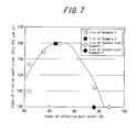
- the calculated results are shown in FIG. 7 .
- the index of the effective belt width depicted as transverse in FIG. 7 refers to an index of a proportion to the effective belt width of the tire of Conventional Example 1.
- the pneumatic tire 30 of the second embodiment having the tire size of 195/65R15 is expected to have the maximum ⁇ at the effective width EW being within 85-90 %.
- the present inventor measured the friction coefficient (TT ⁇ , 0°C low ⁇ ) on ice of other example of conventional pneumatic tire in tire size of 205/65R15 (hereinafter, referred to as the tire of Conventional Example 2), and set this friction coefficient as an index of 100. Then, the present inventor manufactured tire having the tire size of 205/65R15 according to the pneumatic tire 30 of the second embodiment, in which the effective belt width EW is in the vicinity of 85% of the tread width TW, and measured the friction coefficient of this tire on ice as relative index with respect to the tire of Conventional Example 2. The test results are together shown in FIG. 7 .
- the present inventor for tires each having the size of 205/65R15, conducted performance tests and evaluated the performances with using one example of the pneumatic tire 10 of the second embodiment (hereinafter, referred to as the tire of Example 2) and the tire of Conventional Example 2.
- the tire of Example 2 the bead filler height BH is 53mm.
- the distance D between the first belt end 14LE and the second belt end 34UE is approximately 15mm, and the effective belt width EW is 85%.
- each evaluation item filled with "100" of the tire of Conventional Example 1 refers to index of the tire of Example 2 calculated as relative evaluation, when the rating index of the tire of Conventional Example 2 is set as a reference value of 100.
- the each evaluation item as filled with other than "100" refers to the rating index obtained by driver's feeling test. In each evaluation item, the larger the index is, the better performance is.
- the present inventor for tires each having tire size of 195/65R15, conducted performance tests and evaluated the performances with using two examples of the pneumatic tire 40 of the third embodiment (hereinafter, referred to as the tire of Example 3, the tire of Example 4) and the tire of Conventional Example 1.
- the effective bead width EW is 81% of the tread width TW
- the bead filler height BH is 16mm
- the bead filler height is 25% of the tire cross sectional height SH
- the distance D between the first belt end 14LE and the second belt end 34UE is 15mm.
- the effective tread width EW is 85% of the tread width TW, and conditions other than this are same as those of the tire of the Example 3.
- Table 2 The measurements of respective tire and other test conditions, and evaluation results are together shown in Table 2.
- the each evaluation item filled with "100" of the tire of Conventional Example 1 refers to the indexes of the tires of Example 3 and 4 calculated as relative evaluation, when the evaluation index of the tire of Conventional Example 1 is set as the reference value of 100.
- the each evaluation item as filled with other than "100” refers to the rating index obtained by driver's feeling test. In each evaluation item, the larger the index is, the better performance is.
- the present inventor For the tire of Conventional Example 2 and the tire of Example 2 applied the regular internal pressure, the present inventor respectively measured an eccentric amount at each position in the tire width direction.
- the present inventor prepared a pneumatic tire for comparison (hereinafter, referred to as the tire of Comparative Example), applied the regular internal pressure, and measured the eccentric amount of that at each position in the tire width direction, as well.
- the tire of Comparative Example has the conditions in that, the tire size is 205/65R15, the proportion of the effective belt width EW to the tread width TW equal to that of the tire of Conventional Example 2, an inner layer is provided, and the bead filler height is within the range of 15-40% of the tire cross sectional height.
- FIG. 8 a difference of the eccentric amount with respect to that of the tire center (the tire equator) is depicted. It can be understood from FIG. 8 , in both of the tire of the Example 2 and the tire of Comparative Example, the difference of the eccentric amount at shoulder end was decreased relative to that of the tire of Conventional Example 2.
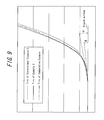
- the present inventor measured the leading angle (at a tread-in side, an angle of a ground-contact end portion to the tire the road surface in the tire circumferential direction) with applying the regular internal pressure and the regular load to those tires. Measured results are shown in FIG. 9 .
- the leading angle ⁇ of the tire of Example 2 is smaller than the leading angle ⁇ of the tire of Conventional Example 2.
- the leading angle of the tire of Comparative Example is almost same as the leading angle ⁇ of the tire of Example 2. The reason for this is assumed that, in the tire of Example 2 and the tire of Comparative Example, an eccentric deformation at the shoulder portion is respectively smaller than that of the tire of Conventional Example 2.
- Example 3 For the tire of Conventional Example 2, the tire of Example 2, and the tire of Comparative Example, the present inventor conducted tests with running a passenger vehicle on a normal load not on ice or snow, and evaluated the tire performances by driver's feeling. The evaluated results are shown in Table 3.
- Example 2 For the tire of Conventional Example 2, and the tire of Example 2, the present inventor conducted wear test with the vehicle running on the normal load not on ice or snow, and evaluated the tire performances by measuring wear amount. The measured result and evaluated result are shown in Table 4.
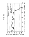
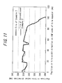
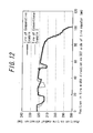
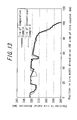
- the present inventor measured how much the shapes of the tire of Example 2 and the tire of Comparative Example change relative to that of the tire of Conventional example 2, with using laser beam. Measured results are shown in FIG. 10 - FIG. 13 (4 drawings). It can be understood from FIG. 10 - FIG. 13 , the shapes of the tire of Example 2 and the tire of Comparative Example are respectively almost same as that of tire of Conventional Example 2.
- the present inventor conducted a test to examine how much the friction coefficient against the ice road or snow road of the tire of Example 2 and the tire of Comparative Example is increased relative to that of tire of Conventional Example.
- indexes of the tire of Example 2 and the tire of Comparative Example are calculated as the relative evaluations.
- the test result is shown in FIG. 14 .
- each the friction coefficient of the tire of Example 2 and the tire of Comparative Example is higher than that of the tire of Conventional Example. It can be also understood from FIG. 14 , especially in the tire of Example 2, at the condition of 0°C in vicinity ("0°C low ⁇ ) that water is most likely to appear, the friction coefficient is significantly improved.
- the present inventor prepared the tires each having the tire size of 175/65R14 in which the distance between the first belt end and the second belt end is changed into 5mm, 6mm, 7.5mm, 10mm, and 15mm as parameter, and measured the friction coefficient (TT ⁇ , 0°C low ⁇ ) on the ice road. Then, with the rating index of tire in which the distance between the first belt end and second belt end is 5mm as 100, each index of other tires was calculated as the relative evaluation.
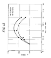
- the present inventor prepared the tires having tire size of 155/70R13 in which the distance between the first belt end and the second belt end is changed into 5mm, 6mm, 7.5mm, 10mm, and 15mm as parameter, and measured the friction coefficient (TT ⁇ , 0°C low ⁇ ) on ice the road. Then, with the rating index of tire in which the distance between the first belt end and second belt end is 5mm as 100, each index of other tires was calculated as the relative evaluation. It is referred that the higher the index is, the better performance is, in other words, the higher the friction coefficient on ice road is. Test result (evaluated result) is shown in FIG. 15 . It can be understood from FIG.
- the friction coefficient on the ice road is improved 3% relative to that of the distance between the first belt end and the second belt end being 5mm, therefore, it is realized that the friction coefficient is a significant increased. It is also realized that spacing of 10mm with each other is more preferably.
- the present inventor prepared a tire in which a tread rubber has 30MPa of E' (dynamic elastic modulus) and a tire in which a tread rubber has 50MPa of E', for each tires, the ground-contact area is respectively measured at 52.1Hz of frequency, 1.0% of amplitude, 0°C of temperature.
- E' dynamic elastic modulus
- a tread rubber has 50MPa of E'
- the ground-contact area is respectively measured at 52.1Hz of frequency, 1.0% of amplitude, 0°C of temperature.
- the E' When the E' is smaller, the increase of the ground-contact area of the tread due to the reduction of the belt tension at shoulder portion can be confirmed.
- the E' should be at least 3MPa in order to secure the function as the tread rubber of tire. Therefore, it is expected that, in the present invention, when the tread rubber in which the E' is less than 30MPa is applied to the ice and snow tire, the great effect is provided.
Landscapes
- Engineering & Computer Science (AREA)
- Mechanical Engineering (AREA)
- Tires In General (AREA)
- Pharmaceuticals Containing Other Organic And Inorganic Compounds (AREA)
- Acyclic And Carbocyclic Compounds In Medicinal Compositions (AREA)
- Transition And Organic Metals Composition Catalysts For Addition Polymerization (AREA)
Abstract
Description
- The present invention relates to a pneumatic tire having a two-belt structure, and more specifically, to a pneumatic tire optimized for running especially on ice and snow.
- Various technologies have been provided for a pneumatic tire to improve tire performances such as driving and breaking performances on ice and snow. For example, in
JP2001-206022A - Meanwhile, suppose that the tire performances can be improved without provision of such sub rubber layers, it is possible to provide a pneumatic tire having a simple constitution and improved performances.
- It is an object of the present invention, with taking the above matter into account, to provide a pneumatic tire having a simple constitution and improved performances especially on ice and snow.
- An invention recited in
claim 1 provides a pneumatic tire having a two-belt structure, in which a width of a first belt is larger than a width of a second belt, and the width of the second belt is within a range of 80 to 95 % of a tread width. - The term "tread width" as used herein means the distance between tread ends as measured in the tire width direction. The term "tread ends" means the outermost ground contact portions in the tire width direction when the tire is placed on a standard rim stipulated in the JATMA Year Book (2006 edition; Japan Automotive Tire Manufactures Association standard), the tire is inflated to an internal pressure of 100% of the air pressure (maximum air pressure) corresponding to the maximum load capability (a load indicated by bold characters in table corresponding to internal pressure/load capability) in the applied size/ply rating in JATMA Year Book, and the tire bears the maximum load capability. It will be noted that when the TRA standard or the ETRTO standard is used in the location of use or the location of manufacture, these respective standards are followed.
- According to the invention of
claim 1, there is provided a tire structure in which the width of the second belt is smaller than the width of the first belt and the tread width, so that a width of a belt portion as a cross belt layer get smaller. Thus, even though the first belt has an enough width, the belt tension at the belt portion where the cross belt layer does not exist is reduced. Therefore, a leading angle of the tire outer surface (an angle between a road surface and a tire land portion) in the vicinity of the ground-contact end of the tire becomes smaller. This suppress intakes of water slightly produced due to the ground contact of the tire into the ground contacting plane, thereby making it possible to improve the tire performances such as the driving performance and the breaking performance. - The width of the second belt smaller than 80% of the tread width is not preferred, since a shape of the ground contacting plane is deformed largely. Also, the width of second belt larger than 95% of the tread width is not preferred, since the effect of decreasing the leading angle as discussed is reduced.
- In an invention recited in
claim 2, the width of second belt is within a range of 83-90% of the tread width. This range falls within a range exerting a particularly greater effect, so that the effect of the invention recited inclaim 1 can be further enhanced. - In an invention recited in claim 3, the width of the first belt is within a range of 95-102% of the tread width. Due to this configuration, the shear rigidity of the belt at the shoulder region is increased, which is beneficial in terms of wear.
- When the width of the first belt is smaller than 95% of the tread width, uneven wear tends to occur. On the other hand, when the width of the first belt is larger than 102% of the tread width, the first belt ends may be close to side rubbers due to a production deviation.
- In an invention recited in claim 4, the first belt end and the second belt end are spaced by 6 mm or more. Thus, a tension at the shoulder is decreased further to enhance the effect of the invention recited in
claim 1. - In an invention recited in
claim 5, the first belt end and the second belt end are spaced by 10 mm or more. This allows the effect of the invention recited in claim 4 to be more remarkable. - In an invention recited
claim 6, a bead filler height is within a range of 15-40% of a tire cross sectional height. - According to the invention recited
claim 6, since the bead filler height is suppressed within the range of 15-40% of the tire cross sectional height, the radius of a case line at the tire side portion is made larger and then the tension at the side portion is increased, and the belt tension at the shoulder portion is, in turn, decreased. Therefore, it is possible to amplify the effect of the invention recited inclaim 1 more. - When the bead filler height is smaller than 15% of the tire cross sectional height, it tends to be difficult to manufacture the tire. On the other hand, when the bead filler height is larger than 40% of the tire cross sectional height, the effect obtained by
claim 6 unlikely to be exerted. - It is preferred that, the bead filler height (the region across which the bead filler lies) is within a range of 0.5*H or less, where H is a distance between the tire height position at the tire maximum width position and a rim outer circumference in condition of mounting the tire to the rim and setting the inflation inner pressure as 30 KPa. It is more preferred that the bead filler height is within a range of 0.4*H or less.
- In an invention recited in claim 7, a dynamic elastic modulus of a tread rubber is within a range of 3-20 MPa. The reason for the enlarging the distance between the first belt end and the second belt end is to reduce the belt tension at the shoulder portion as discussed above. As a result, the ground-contact length is increased to enlarge the ground-contact area, so that a friction coefficient on ice is increased, as discussed above. Here, the harder tread rubber is difficult to be deformed, thus, it is difficult to effectively enlarge the ground-contact area with reducing the belt tension. In the summer tire which is not intended for use on ice and snow, the dynamic elastic modulus of the tread rubber is within a range of 25-50 MPa where the dynamic elastic modulus is set relatively high. In such range, even though the distance between the first belt end and the second belt end is enlarged, it is difficult to improve the tire performances on ice and snow. The dynamic elastic modulus of the tread rubber within the range of 3-20 MPa makes the tread rubber moderately soft, so that the tire performances on the ice and snow is remarkably improved by the enlargement of the distance between the first belt end and the second belt end.
- According to present invention, a pneumatic tire having a simple constitution and improved tire performances especially on ice and snow can be provided.
-
-
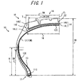
FIG. 1 is cross-sectional view of a tire in accordance with a first embodiment in the tire radial direction: -
FIG. 2 shows a foot print shape of a tread portion of the tire in accordance with the first embodiment; -
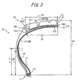
FIG. 3 is a cross-sectional view of a tire in accordance with a second embodiment in the tire radial direction; -
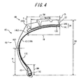
FIG. 4 is a cross-sectional view of a tire in accordance with a third embodiment in the tire radial direction; -
FIG. 5 is a graph showing test results in Test Example 1. -
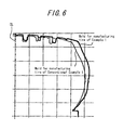
FIG. 6 is a tire radial directional cross-sectional view in the tire radial direction schematically showing a shape of a tire mold in Test Example 2. -
FIG. 7 is a graph showing test results in Test Example 3. -
FIG. 8 is a graph showing test results in Test Example 5. -
FIG. 9 is a side view schematically showing surface shapes of shoulder portions of respective tires in Test Example 6. -
FIG. 10 shows results of measurement of tire shape in Test Example 9. -
FIG. 11 shows results of measurement of tire shape in Test Example 9. -
FIG. 12 shows results of measurement of tire shape in Test Example 9. -
FIG. 13 shows results of measurement of tire shape in Test Example 9. -
FIG. 14 is a graph showing test results in Test Example 10. -
FIG. 15 is a graph showing test results in Test Example 11. -
- 10
- Pneumatic tire
- 13
- Bead filler
- 14LE
- First belt end
- 14UE
- Second belt end
- 30
- Pneumatic tire
- 34UE
- Second belt end
- 40
- Pneumatic tire
- 43
- Bead filler
- 1W
- Width of the first belt
- 2W
- Width of the second belt
- BH
- Bead filler height
- SH
- Tire cross sectional height
- TW
- Tread width
- Hereinafter, with reference to embodiments, the mode of the present invention will be described. Like reference numerals are used throughout the description following the first embodiment to refer to similar components and those descriptions are omitted.
- A first embodiment is described here. As shown in
FIG. 1 , apneumatic tire 10 of the embodiment is a winter tire used in traveling on ice and snow road such as a snow road and an ice road. - The
pneumatic tire 10 according to the first embodiment comprises acarcass 12 formed of a single-layer structure or a multilayer structure. Thecarcass 12 includes turn-upportions 12E in which the both side parts of the carcass are turned up respectively around abead core 11C of abead portion 11. In thebead portion 11, abead filler 13 is provided between the turn-upportion 12E and acarcass body 12M. - A
belt layer 14 is embedded radially outside of thecrown portion 12C of thecarcass 12. A tread portion 18 (additionally, refer toFIG. 2 ) having grooves is provided radially outside of thebelt layer 14.
Thetread portion 18 is provided with a plurality of circumferential grooves (main grooves) 22 extending along the circumferential direction and a plurality of lateral grooves 24 (refer toFIG. 2 ) intersecting the circumferential direction on both sides of the tire equator CL. The end of the eachlateral grooves 24 is communicated with thecircumferential grooves 22 or extends across the tread ends T to drain water to outside in the tire width direction. - Although the tread width TW refers to the distance between both of the tread ends T in the tire width direction, in the present embodiment, that is the same as a distance between both of parts having the smallest radius in a square shoulder of the tire outer surface.
- In the embodiment, since the
belt layer 14 composed of afirst belt 14L and asecond belt 14U disposed on the outer side of tire radial direction of thefirst belt 14L, thepneumatic tire 10 has a two-belt structure. A first belt width (a width of thefirst belt 14L) 1W is larger than a second belt width (a width of thesecond belt 14U) 2W, thesecond belt width 2W is within a range of 90-95% of the tread width TW, and an effective belt width EW is within a range of 90-95% of the tread width TW. Here, the effective belt width EW refers to a width of the belt portion where thefirst belt 14L and thesecond belt 14U are overlapped with each other. - According to this configuration, there is provided a tire structure in which the
second belt width 2W is smaller than thefirst belt width 1 W and the tread width TW, so that thewidth 2W of a cross belt layer formed by the second belt get smaller. Thus, even though thefirst belt 14L has an enough width, a belt tension at the both ends of the belt in the width direction where the belt forming the cross belt layer (i.e., thesecond belt 14U) does not exist is reduced. Thus, in a distribution of eccentric amount under the load, a relative eccentric amount at theshoulder portion 16 in comparison with a eccentric amount at a portion near the tire center (i.e., at a portion near the tire equator CL) is reduced. Therefore, a leading angle, i.e., an angle between a road surface and a tire land portion in the vicinity of the ground-contact end of the tire becomes smaller. This suppress intakes of water slightly produced due to the ground contact of the tire into the ground contacting plane, thereby making it possible to improve the tire performances such as the driving performance and breaking performance. - The
first belt width 1 W is set within the range of 95-102% of the tread width TW. Due to this configuration, the shear rigidity of the belt at the shoulder region is increased, which is beneficial in terms of wear. - Next, the second embodiment is described. As shown in
FIG. 3 , apneumatic tire 30 of present embodiment has asecond belt 34U in place of thesecond belt 14U of the first embodiment. Abelt layer 34 of thepneumatic tire 30 is composed of thefirst belt 14L and thesecond belt 34U. - The
second belt 34U has a smaller width than that of thesecond belt 14U. In the present embodiment, a proportion of the effective belt width EW with respect to the tread width TW is set smaller than that of the first embodiment. As a result, a distance D between the first belt end 14LE (the end of thefirst belt 14L in the width direction) and the second belt end 34UE (an end of thesecond belt 34U in the width direction) is set to 10mm or more. - According to the present embodiment, since water slightly produced due to the ground contact of the tire is less likely to be taken into the ground contacting plane, it is possible to further improve the tire performances such as the driving performance and breaking performance.
- It is noted that significant improvements of the performances such as the driving performance and the breaking performance are obtained even if the distance D is 6mm or more instead of 10mm or more.
- Next, a third embodiment is described. As shown in
FIG. 4 , apneumatic tire 40 of the present embodiment differs from thepneumatic tire 30 of the second embodiment in thatbead fillers 43 in which each bead filler height BH is set within a range of 15-40% of the tire cross sectional height SH is used in place of thebead fillers 13. That is, the bead filler is downsized. - According to present embodiment, due to the smaller bead filler height BH within the range of 15-40% of the tire cross sectional height SH, the radius of a case line at the
tire side portion 48 is enlarged to increase a tension at the side portion, whereby, the belt tension at theshoulder portion 46 is, in turn, decreased. Therefore, with respect to the first embodiment, since water slightly produced due to the ground contact of the tire is less likely to be taken into the ground contacting plane, it is possible to further improve the tire performances such as the driving performance and breaking performance. - The region across which the
bead filler 43 lies is within the range of 0.4*H or less, where H is the distance between the tire height position at the tiremaximum width position 40P in condition of mounting the tire to the rim and setting the inflation inner pressure as 30 KPa and a rim outer circumference. Therefore, it is possible to amplify the above effect of present embodiment more. - In order to increase the ground-contact area by optimizing the tire shape, the present inventor prepared test tires whose RRC as a parameter is respectively changed from the viewpoint of optimizing (1) only the tire shape, (2) the tire shape together with the belt angle, and conducted a test for how much increase of the ground-contact area could be made. The term RRC as used herein means a value obtained by dividing a rolling resistance by a road.
- In the present test example, tire size of each tire was 195/65R15, and, with assuming the RRC and the ground contact area of one example of conventional pneumatic tires (hereinafter, referred to as the tire of Conventional Example 1) respectively as an index of 100, each relative index of cases (1) and (2) with respect to the tire of Conventional Example 1 is measured. The test results are shown in
FIG. 5 . - It can be understood from
FIG. 5 that, (1) the optimization of the tire shape alone gives an increase of the ground-contact area by 6-7%, while (2) the optimizations of the tire shape together with the belt angle gives an increase of the ground-contact area up to 9%. It is noted that an optimum belt angle is 56 degrees, and it is preferred that the belt angle is within a range of 45-74 degrees in order to increase the ground-contact area in an efficient fashion. - In order to verify the effects of the present invention, the present inventor conducted performance tests and evaluated the performances with using one example of the
pneumatic tire 10 of the first embodiment (hereinafter, referred to as the tire of Example 1) and the tire of Conventional Example 1, where each tire size is 195/65R15. Here, in the tire of the Example 1, the effective belt width EW is 94% of the tread width TW, the distance D between the first belt end 14LE and the second belt end 14UE is 5mm, and thefirst belt width 1 W is 100% of the tread width TW. Also, the bead filler height BH is 53mm. -
FIG. 6 shows the shape of a mold in the tire radial section depicted as bold line for manufacturing the tire of Example 1 and the shape of a mold in the tire radial section depicted as fine line for manufacturing the tire of Conventional Example 1. The tread width TW of the tire of Example 1 is larger than that of the tire of Conventional Example 1. Measurements of respective tires and other test conditions in the present Test Example are shown in Table 1. -


- In Table 1, "OD" denotes the outside diameter, and "SW" denotes the maximum width. "TW" denotes the tread width, and "CR" denotes the radius at a crown portion. "FP" denotes the foot print. "IB (ABS) denotes the breaking performance on ice with activating an Anti Lock Brake System, and "IA" denotes the driving performance (accelerating performance) on ice. "TTµ" denotes an indoor friction testing machine.
- In present test example, after all of tires are assembled to a regular rim and mounted on a vehicle, the test is conducted under the conditions of a regular internal pressure and a regular load. The term of "regular rim" as used herein refers to the standard rim for an applicable size as specified in the YEAR BOOK of 2006 edition issued by JATMA, for example, and the terms of "regular load" and "regular internal pressure" respectively refer to a maximum load and an air pressure for the maximum load, for the applicable size/ply rating specified as well in the YEAR BOOK of 2006 edition issued by JATMA. When, the TRA Standard or ETRTO Standard is applied in a place of use or manufacture, the definitions shall be conformed to these standards.
- In the present Test Example, for carrying out the performance evaluation, with evaluations of the tire of Conventional Example 1 defined as indexes of 100, indexes of the of Example 1 are calculated as the relative evaluation. Evaluated results are shown together in Table 1. In Table 1, the larger the index is, the better performance is. It can be understood from Table 1, with the tire of Example 1, in almost all evaluation items, the each evaluation is respectively exalted in comparison to that of the tire of Conventional Example 1. It is noted that the actual ground-contact area is calculated based on the FP.
- In addition, the actual ground-contact area of a tire of Comparative Example as described hereinafter was measured, and it turned out that its actual ground-contact area was larger than that of the tire of Conventional Example 1 and smaller than that of the tire of Example 1.
- The present inventor manufactured tires having the tire size of 195/65R15 according to the
pneumatic tire 30 of the second embodiment with varying effective belt width EW as a parameter. - Then, with assuming the effective belt width EW and the friction coefficient (TTµ, 0 °C lowµ) on ice of the tire of Conventional Example 1 respectively as an index of 100, the friction coefficient at each the effective belt width is measured as the relative index with respect to that of the tire of Conventional Example 1. The calculated results are shown in
FIG. 7 . Here, the index of the effective belt width depicted as transverse inFIG. 7 refers to an index of a proportion to the effective belt width of the tire of Conventional Example 1. - It can be understood from
FIG. 7 that thepneumatic tire 30 of the second embodiment having the tire size of 195/65R15 is expected to have the maximum µat the effective width EW being within 85-90 %. - Also, the present inventor measured the friction coefficient (TTµ, 0°C lowµ) on ice of other example of conventional pneumatic tire in tire size of 205/65R15 (hereinafter, referred to as the tire of Conventional Example 2), and set this friction coefficient as an index of 100. Then, the present inventor manufactured tire having the tire size of 205/65R15 according to the
pneumatic tire 30 of the second embodiment, in which the effective belt width EW is in the vicinity of 85% of the tread width TW, and measured the friction coefficient of this tire on ice as relative index with respect to the tire of Conventional Example 2. The test results are together shown inFIG. 7 . - It can be understood from
FIG. 7 , with thepneumatic tire 30 of the second embodiment, even when the tire size is 205/65R15, it is expected that the µ is maximized at the effective width EW being in vicinity of 85% of the tread width TW. - In addition, the present inventor, for tires each having the size of 205/65R15, conducted performance tests and evaluated the performances with using one example of the
pneumatic tire 10 of the second embodiment (hereinafter, referred to as the tire of Example 2) and the tire of Conventional Example 2. Here, in the tire of the Example 2, the bead filler height BH is 53mm. The distance D between the first belt end 14LE and the second belt end 34UE is approximately 15mm, and the effective belt width EW is 85%. - The measurements of respective tire and other test conditions are shown in Table 2.

- In Table 2, the meanings "IA", "IB" and "ABS" are respectively same as above descriptions (the descriptions in Test Example 2). The term of Lock means that the test had been conducted in condition of the tire being locked not to rotate. The term of SA means the acceleration performance on ice, the term of SB means the breaking performance on snow. The term of "0°C low µ" means a road surface in which the friction coefficient is low due to an existence of large volume of water on the ice road surface at 0°C. It is noted that blanks mean date is not taken.
- In the present test example, after all of tires are assembled to the regular rim and mounted on the vehicle, and the test is conducted under the conditions of the regular internal pressure and the regular load. Results of the evaluations are shown together in Table 2.
As to the performance evaluations as shown in Table 2, the each evaluation item filled with "100" of the tire of Conventional Example 1 refers to index of the tire of Example 2 calculated as relative evaluation, when the rating index of the tire of Conventional Example 2 is set as a reference value of 100. The each evaluation item as filled with other than "100" refers to the rating index obtained by driver's feeling test. In each evaluation item, the larger the index is, the better performance is. - In addition, the present inventor, for tires each having tire size of 195/65R15, conducted performance tests and evaluated the performances with using two examples of the
pneumatic tire 40 of the third embodiment (hereinafter, referred to as the tire of Example 3, the tire of Example 4) and the tire of Conventional Example 1. Here, in the tire of the Example 3, the effective bead width EW is 81% of the tread width TW, the bead filler height BH is 16mm, the bead filler height is 25% of the tire cross sectional height SH, and the distance D between the first belt end 14LE and the second belt end 34UE is 15mm. In the tire of Example 4, the effective tread width EW is 85% of the tread width TW, and conditions other than this are same as those of the tire of the Example 3. The measurements of respective tire and other test conditions, and evaluation results are together shown in Table 2. - As is the case with 205/65R15, as to the performance evaluations as shown in Table 2, the each evaluation item filled with "100" of the tire of Conventional Example 1 refers to the indexes of the tires of Example 3 and 4 calculated as relative evaluation, when the evaluation index of the tire of Conventional Example 1 is set as the reference value of 100. The each evaluation item as filled with other than "100" refers to the rating index obtained by driver's feeling test. In each evaluation item, the larger the index is, the better performance is.
- It can be understood from Table 2, with the tire of Example 2, in almost all evaluation items, the evaluations are exalted in comparison to those of the tire of Conventional Example 2. With the tire of Example 3, in almost all evaluation items, the evaluations are exalted in comparison to those of the tire of Conventional Example 1.
With the tire of Example 4, although only the performance of "TTµ" is tested, in all items (three items) as tested, evaluations are exalted in comparison to those of the tire of Conventional Example 1. In the condition of 0°C in vicinity (0°C lowµ) that water is most likely to appear on the ice road surface, the friction coefficient (µ) is significantly improved. - For the tire of Conventional Example 2 and the tire of Example 2 applied the regular internal pressure, the present inventor respectively measured an eccentric amount at each position in the tire width direction. In addition, the present inventor prepared a pneumatic tire for comparison (hereinafter, referred to as the tire of Comparative Example), applied the regular internal pressure, and measured the eccentric amount of that at each position in the tire width direction, as well. Here, the tire of Comparative Example has the conditions in that, the tire size is 205/65R15, the proportion of the effective belt width EW to the tread width TW equal to that of the tire of Conventional Example 2, an inner layer is provided, and the bead filler height is within the range of 15-40% of the tire cross sectional height.
- Measured results are shown in
FIG. 8 . InFIG. 8 , a difference of the eccentric amount with respect to that of the tire center (the tire equator) is depicted.
It can be understood fromFIG. 8 , in both of the tire of the Example 2 and the tire of Comparative Example, the difference of the eccentric amount at shoulder end was decreased relative to that of the tire of Conventional Example 2. - For the tire of Conventional Example 2, the tire of Example 2, and the tire of Comparative Example, the present inventor measured the leading angle (at a tread-in side, an angle of a ground-contact end portion to the tire the road surface in the tire circumferential direction) with applying the regular internal pressure and the regular load to those tires. Measured results are shown in
FIG. 9 . - It can be understood from
FIG. 9 , at the shoulder portions, the leading angle θof the tire of Example 2 is smaller than the leading angle α of the tire of Conventional Example 2. The leading angle of the tire of Comparative Example is almost same as the leading angle θ of the tire of Example 2. The reason for this is assumed that, in the tire of Example 2 and the tire of Comparative Example, an eccentric deformation at the shoulder portion is respectively smaller than that of the tire of Conventional Example 2. - It is noted that, when a kicking angle at a tire trailing side was also measured as well, the trailing angles of the tire of Example 2 and the tire of Comparative Example were smaller than that of the tire of Conventional Example 2.
- For the tire of Conventional Example 2, the tire of Example 2, and the tire of Comparative Example, the present inventor conducted tests with running a passenger vehicle on a normal load not on ice or snow, and evaluated the tire performances by driver's feeling. The evaluated results are shown in Table 3.

- In Table 3, the riding comfortability, the steering stability on dry road, and the steering stability on wet road are shown as an absolute value. In the deceleration, the acceleration in the transverse direction, and the turning performance on wet road, with the rating index of the tire of Conventional Example 2 as 100, indexes of the tire of Example 2 and the tire of Comparative Example are shown as the relative evaluation. In the absolute value and the relative evaluation, the larger the index is, the better performance is.
- It can be understood from Table 3, with the tire of Example 2 and the tire of Comparative Example, in almost all evaluation items, the evaluations are exalted in comparison to those of the tire of Conventional Example 2.
- For the tire of Conventional Example 2, and the tire of Example 2, the present inventor conducted wear test with the vehicle running on the normal load not on ice or snow, and evaluated the tire performances by measuring wear amount. The measured result and evaluated result are shown in Table 4.

- In Table 4, as to the performance evaluation, the larger the value is, the better performance is. It can be understood from Table 4, in relating to both of the average wear resistance (i.e., refers to a degree of wearing averagely not unevenly) and the estimated travelable distance on ice, the evaluations of the tire of Example 2 are higher than those of the tire of Conventional Example 2.
- The present inventor measured how much the shapes of the tire of Example 2 and the tire of Comparative Example change relative to that of the tire of Conventional example 2, with using laser beam. Measured results are shown in
FIG. 10 -FIG. 13 (4 drawings).
It can be understood fromFIG. 10 -FIG. 13 , the shapes of the tire of Example 2 and the tire of Comparative Example are respectively almost same as that of tire of Conventional Example 2. - The present inventor conducted a test to examine how much the friction coefficient against the ice road or snow road of the tire of Example 2 and the tire of Comparative Example is increased relative to that of tire of Conventional Example. In the present test, with the rating index of the tire of Conventional Example 2 under each road condition as reference value of 100, indexes of the tire of Example 2 and the tire of Comparative Example are calculated as the relative evaluations. The test result is shown in
FIG. 14 . InFIG. 14 , the higher the rating index is, the better performance is, in other words, the higher the friction coefficient is. - As shown in
FIG. 14 , in any road conditions, each the friction coefficient of the tire of Example 2 and the tire of Comparative Example is higher than that of the tire of Conventional Example. It can be also understood fromFIG. 14 , especially in the tire of Example 2, at the condition of 0°C in vicinity ("0°C low µ) that water is most likely to appear, the friction coefficient is significantly improved. - The present inventor prepared the tires each having the tire size of 175/65R14 in which the distance between the first belt end and the second belt end is changed into 5mm, 6mm, 7.5mm, 10mm, and 15mm as parameter, and measured the friction coefficient (TTµ, 0°C low µ) on the ice road. Then, with the rating index of tire in which the distance between the first belt end and second belt end is 5mm as 100, each index of other tires was calculated as the relative evaluation.
In addition, the present inventor prepared the tires having tire size of 155/70R13 in which the distance between the first belt end and the second belt end is changed into 5mm, 6mm, 7.5mm, 10mm, and 15mm as parameter, and measured the friction coefficient (TTµ, 0°C lowµ) on ice the road. Then, with the rating index of tire in which the distance between the first belt end and second belt end is 5mm as 100, each index of other tires was calculated as the relative evaluation. It is referred that the higher the index is, the better performance is, in other words, the higher the friction coefficient on ice road is.
Test result (evaluated result) is shown inFIG. 15 . It can be understood fromFIG. 15 , in the tire in which the distance between the first belt end and second belt end is 6mm, the friction coefficient on the ice road is improved 3% relative to that of the distance between the first belt end and the second belt end being 5mm, therefore, it is realized that the friction coefficient is a significant increased. It is also realized that spacing of 10mm with each other is more preferably. - The present inventor prepared a tire in which a tread rubber has 30MPa of E' (dynamic elastic modulus) and a tire in which a tread rubber has 50MPa of E', for each tires, the ground-contact area is respectively measured at 52.1Hz of frequency, 1.0% of amplitude, 0°C of temperature. As a result, there is no much difference of the ground-contact area as compared the tread rubber having 30MPa of E' and the tread rubber having 50MPa of E'. Meanwhile, it is realized that, with the E' as 20MPa, since the tread rubber is soft, the increase of the ground-contact area of the tread is remarkable due to the reduction of the belt tension at the shoulder portion. When the E' is smaller, the increase of the ground-contact area of the tread due to the reduction of the belt tension at shoulder portion can be confirmed. However, the E' should be at least 3MPa in order to secure the function as the tread rubber of tire. Therefore, it is expected that, in the present invention, when the tread rubber in which the E' is less than 30MPa is applied to the ice and snow tire, the great effect is provided.
- The present invention has been described with reference to the embodiments, however, these embodiments are only one example among many, various changes may be made without departing from the scope of the appended claims the present invention is not limited to the precise embodiments disclosed.
Claims (7)
- A pneumatic tire having a two-belt structure, wherein a width of a first belt is larger than a width of a second belt, and
the width of the second belt is within a range of 80-95% of a tread width. - The pneumatic tire according to claim 1, wherein the width of the second belt is within a range of 83-90% of the tread width.
- The pneumatic tire according to claim 1, wherein the width of the first belt is within a range of 95-102% of the tread width.
- The pneumatic tire according to claim 1, wherein a first belt end and a second belt end are spaced by 6mm or more.
- The pneumatic tire according to claim 4, wherein the first belt end and the second belt end are spaced by 10mm or more.
- The pneumatic tire according to claim 1, wherein a bead filler height is within a range of 15-40% of a tire cross sectional height.
- The pneumatic tire according to claim 1, wherein a dynamic elastic modulus of a tread rubber is within a range of 3-20MPa.
Applications Claiming Priority (3)
| Application Number | Priority Date | Filing Date | Title |
|---|---|---|---|
| JP2007184261 | 2007-07-13 | ||
| JP2008170202 | 2008-06-30 | ||
| PCT/JP2008/062721 WO2009011344A1 (en) | 2007-07-13 | 2008-07-14 | Pneumatic tire |
Publications (3)
| Publication Number | Publication Date |
|---|---|
| EP2179866A1 true EP2179866A1 (en) | 2010-04-28 |
| EP2179866A4 EP2179866A4 (en) | 2011-03-02 |
| EP2179866B1 EP2179866B1 (en) | 2012-02-08 |
Family
ID=40259677
Family Applications (1)
| Application Number | Title | Priority Date | Filing Date |
|---|---|---|---|
| EP08791146A Not-in-force EP2179866B1 (en) | 2007-07-13 | 2008-07-14 | Pneumatic tire |
Country Status (5)
| Country | Link |
|---|---|
| EP (1) | EP2179866B1 (en) |
| JP (1) | JPWO2009011344A1 (en) |
| AT (1) | ATE544616T1 (en) |
| ES (1) | ES2381412T3 (en) |
| WO (1) | WO2009011344A1 (en) |
Families Citing this family (3)
| Publication number | Priority date | Publication date | Assignee | Title |
|---|---|---|---|---|
| CN114028666B (en) | 2015-03-31 | 2025-10-28 | 费雪派克医疗保健有限公司 | User interface and system for supplying gas to an airway |
| KR102776008B1 (en) | 2016-08-11 | 2025-03-10 | 피셔 앤 페이켈 핼스케어 리미티드 | A collapsible conduit, patient interface and headgear connector |
| JP7283193B2 (en) * | 2019-04-09 | 2023-05-30 | 横浜ゴム株式会社 | pneumatic tire |
Family Cites Families (12)
| Publication number | Priority date | Publication date | Assignee | Title |
|---|---|---|---|---|
| JPH03143703A (en) * | 1989-10-27 | 1991-06-19 | Sumitomo Rubber Ind Ltd | Radial tire |
| JPH04110205A (en) * | 1990-08-31 | 1992-04-10 | Toyo Tire & Rubber Co Ltd | Radial tier for small truck |
| JPH05201202A (en) * | 1992-01-29 | 1993-08-10 | Bridgestone Corp | Pneumatic tire |
| JP2892904B2 (en) * | 1993-04-16 | 1999-05-17 | 住友ゴム工業株式会社 | Pneumatic tire |
| JPH06305304A (en) * | 1993-04-23 | 1994-11-01 | Sumitomo Rubber Ind Ltd | Pneumatic tire |
| JPH10203109A (en) * | 1997-01-20 | 1998-08-04 | Yokohama Rubber Co Ltd:The | Pneumatic radial tire |
| JP4275210B2 (en) * | 1998-01-27 | 2009-06-10 | 株式会社ブリヂストン | Radial tire |
| JP4298820B2 (en) * | 1998-08-25 | 2009-07-22 | 東洋ゴム工業株式会社 | Rubber composition for studless tire |
| JP4255171B2 (en) * | 1999-07-06 | 2009-04-15 | 住友ゴム工業株式会社 | Pneumatic tire |
| JP4486200B2 (en) | 2000-01-26 | 2010-06-23 | 株式会社ブリヂストン | Pneumatic tire |
| JP4429079B2 (en) * | 2004-05-27 | 2010-03-10 | 株式会社ブリヂストン | Pneumatic tire |
| JP4897283B2 (en) * | 2005-12-12 | 2012-03-14 | 住友ゴム工業株式会社 | Pneumatic tire |
-
2008
- 2008-07-14 AT AT08791146T patent/ATE544616T1/en active
- 2008-07-14 ES ES08791146T patent/ES2381412T3/en active Active
- 2008-07-14 WO PCT/JP2008/062721 patent/WO2009011344A1/en not_active Ceased
- 2008-07-14 JP JP2009523650A patent/JPWO2009011344A1/en active Pending
- 2008-07-14 EP EP08791146A patent/EP2179866B1/en not_active Not-in-force
Non-Patent Citations (2)
| Title |
|---|
| No further relevant documents disclosed * |
| See also references of WO2009011344A1 * |
Also Published As
| Publication number | Publication date |
|---|---|
| EP2179866A4 (en) | 2011-03-02 |
| ES2381412T3 (en) | 2012-05-28 |
| JPWO2009011344A1 (en) | 2010-09-24 |
| WO2009011344A1 (en) | 2009-01-22 |
| ATE544616T1 (en) | 2012-02-15 |
| EP2179866B1 (en) | 2012-02-08 |
Similar Documents
| Publication | Publication Date | Title |
|---|---|---|
| EP2497656B1 (en) | Pneumatic tire | |
| EP2743098B1 (en) | Pneumatic tire | |
| EP3332991B1 (en) | Pneumatic tire | |
| US8881783B2 (en) | Pneumatic tire | |
| CN108284711B (en) | Pneumatic tire | |
| EP2179866B1 (en) | Pneumatic tire | |
| WO2012066766A1 (en) | Pneumatic tire | |
| CN114905894B (en) | Tire with a tire body | |
| CN101848818B (en) | Pneumatic tires for motorcycles | |
| JP4263934B2 (en) | Pneumatic tire | |
| JP2003146015A (en) | Pneumatic tire | |
| EP0778162B1 (en) | Pneumatic tyre | |
| JP4687342B2 (en) | Pneumatic tire | |
| JP2007076594A (en) | Pneumatic tire | |
| JP7731278B2 (en) | Pneumatic radial tires for passenger cars | |
| JP7755475B2 (en) | Pneumatic radial tires for passenger cars | |
| JP7732879B2 (en) | Pneumatic radial tires for passenger cars | |
| JP7731277B2 (en) | Pneumatic radial tires for passenger cars | |
| EP4098460B1 (en) | Pneumatic tire for heavy duty | |
| JP7776323B2 (en) | Pneumatic radial tires for passenger cars | |
| JP7759785B2 (en) | Pneumatic radial tires for passenger cars | |
| JP5164445B2 (en) | Pneumatic tire | |
| US11524527B2 (en) | Pneumatic tire | |
| WO2023105833A1 (en) | Pneumatic radial tire for passenger vehicle | |
| EP2248682A1 (en) | Studless tire |
Legal Events
| Date | Code | Title | Description |
|---|---|---|---|
| PUAI | Public reference made under article 153(3) epc to a published international application that has entered the european phase |
Free format text: ORIGINAL CODE: 0009012 |
|
| 17P | Request for examination filed |
Effective date: 20100202 |
|
| AK | Designated contracting states |
Kind code of ref document: A1 Designated state(s): AT BE BG CH CY CZ DE DK EE ES FI FR GB GR HR HU IE IS IT LI LT LU LV MC MT NL NO PL PT RO SE SI SK TR |
|
| AX | Request for extension of the european patent |
Extension state: AL BA MK RS |
|
| DAX | Request for extension of the european patent (deleted) | ||
| A4 | Supplementary search report drawn up and despatched |
Effective date: 20110201 |
|
| RIC1 | Information provided on ipc code assigned before grant |
Ipc: B60C 1/00 20060101ALI20110126BHEP Ipc: B60C 15/06 20060101ALI20110126BHEP Ipc: B60C 11/00 20060101ALI20110126BHEP Ipc: B60C 9/18 20060101AFI20090209BHEP |
|
| GRAP | Despatch of communication of intention to grant a patent |
Free format text: ORIGINAL CODE: EPIDOSNIGR1 |
|
| RIC1 | Information provided on ipc code assigned before grant |
Ipc: B60C 11/00 20060101ALI20110705BHEP Ipc: B60C 9/18 20060101AFI20110705BHEP Ipc: B60C 15/06 20060101ALI20110705BHEP Ipc: B60C 1/00 20060101ALI20110705BHEP |
|
| GRAS | Grant fee paid |
Free format text: ORIGINAL CODE: EPIDOSNIGR3 |
|
| GRAA | (expected) grant |
Free format text: ORIGINAL CODE: 0009210 |
|
| AK | Designated contracting states |
Kind code of ref document: B1 Designated state(s): AT BE BG CH CY CZ DE DK EE ES FI FR GB GR HR HU IE IS IT LI LT LU LV MC MT NL NO PL PT RO SE SI SK TR |
|
| REG | Reference to a national code |
Ref country code: GB Ref legal event code: FG4D |
|
| REG | Reference to a national code |
Ref country code: AT Ref legal event code: REF Ref document number: 544616 Country of ref document: AT Kind code of ref document: T Effective date: 20120215 Ref country code: CH Ref legal event code: EP |
|
| REG | Reference to a national code |
Ref country code: DE Ref legal event code: R096 Ref document number: 602008013320 Country of ref document: DE Effective date: 20120412 |
|
| REG | Reference to a national code |
Ref country code: SE Ref legal event code: TRGR |
|
| REG | Reference to a national code |
Ref country code: ES Ref legal event code: FG2A Ref document number: 2381412 Country of ref document: ES Kind code of ref document: T3 Effective date: 20120528 |
|
| REG | Reference to a national code |
Ref country code: NL Ref legal event code: VDEP Effective date: 20120208 |
|
| LTIE | Lt: invalidation of european patent or patent extension |
Effective date: 20120208 |
|
| PG25 | Lapsed in a contracting state [announced via postgrant information from national office to epo] |
Ref country code: NO Free format text: LAPSE BECAUSE OF FAILURE TO SUBMIT A TRANSLATION OF THE DESCRIPTION OR TO PAY THE FEE WITHIN THE PRESCRIBED TIME-LIMIT Effective date: 20120508 Ref country code: NL Free format text: LAPSE BECAUSE OF FAILURE TO SUBMIT A TRANSLATION OF THE DESCRIPTION OR TO PAY THE FEE WITHIN THE PRESCRIBED TIME-LIMIT Effective date: 20120208 Ref country code: IS Free format text: LAPSE BECAUSE OF FAILURE TO SUBMIT A TRANSLATION OF THE DESCRIPTION OR TO PAY THE FEE WITHIN THE PRESCRIBED TIME-LIMIT Effective date: 20120608 Ref country code: HR Free format text: LAPSE BECAUSE OF FAILURE TO SUBMIT A TRANSLATION OF THE DESCRIPTION OR TO PAY THE FEE WITHIN THE PRESCRIBED TIME-LIMIT Effective date: 20120208 Ref country code: LT Free format text: LAPSE BECAUSE OF FAILURE TO SUBMIT A TRANSLATION OF THE DESCRIPTION OR TO PAY THE FEE WITHIN THE PRESCRIBED TIME-LIMIT Effective date: 20120208 |
|
| PG25 | Lapsed in a contracting state [announced via postgrant information from national office to epo] |
Ref country code: PL Free format text: LAPSE BECAUSE OF FAILURE TO SUBMIT A TRANSLATION OF THE DESCRIPTION OR TO PAY THE FEE WITHIN THE PRESCRIBED TIME-LIMIT Effective date: 20120208 Ref country code: PT Free format text: LAPSE BECAUSE OF FAILURE TO SUBMIT A TRANSLATION OF THE DESCRIPTION OR TO PAY THE FEE WITHIN THE PRESCRIBED TIME-LIMIT Effective date: 20120608 Ref country code: GR Free format text: LAPSE BECAUSE OF FAILURE TO SUBMIT A TRANSLATION OF THE DESCRIPTION OR TO PAY THE FEE WITHIN THE PRESCRIBED TIME-LIMIT Effective date: 20120509 Ref country code: BE Free format text: LAPSE BECAUSE OF FAILURE TO SUBMIT A TRANSLATION OF THE DESCRIPTION OR TO PAY THE FEE WITHIN THE PRESCRIBED TIME-LIMIT Effective date: 20120208 Ref country code: LV Free format text: LAPSE BECAUSE OF FAILURE TO SUBMIT A TRANSLATION OF THE DESCRIPTION OR TO PAY THE FEE WITHIN THE PRESCRIBED TIME-LIMIT Effective date: 20120208 |
|
| REG | Reference to a national code |
Ref country code: AT Ref legal event code: MK05 Ref document number: 544616 Country of ref document: AT Kind code of ref document: T Effective date: 20120208 |
|
| PG25 | Lapsed in a contracting state [announced via postgrant information from national office to epo] |
Ref country code: CY Free format text: LAPSE BECAUSE OF FAILURE TO SUBMIT A TRANSLATION OF THE DESCRIPTION OR TO PAY THE FEE WITHIN THE PRESCRIBED TIME-LIMIT Effective date: 20120208 |
|
| PG25 | Lapsed in a contracting state [announced via postgrant information from national office to epo] |
Ref country code: DK Free format text: LAPSE BECAUSE OF FAILURE TO SUBMIT A TRANSLATION OF THE DESCRIPTION OR TO PAY THE FEE WITHIN THE PRESCRIBED TIME-LIMIT Effective date: 20120208 Ref country code: RO Free format text: LAPSE BECAUSE OF FAILURE TO SUBMIT A TRANSLATION OF THE DESCRIPTION OR TO PAY THE FEE WITHIN THE PRESCRIBED TIME-LIMIT Effective date: 20120208 Ref country code: EE Free format text: LAPSE BECAUSE OF FAILURE TO SUBMIT A TRANSLATION OF THE DESCRIPTION OR TO PAY THE FEE WITHIN THE PRESCRIBED TIME-LIMIT Effective date: 20120208 Ref country code: CZ Free format text: LAPSE BECAUSE OF FAILURE TO SUBMIT A TRANSLATION OF THE DESCRIPTION OR TO PAY THE FEE WITHIN THE PRESCRIBED TIME-LIMIT Effective date: 20120208 Ref country code: SI Free format text: LAPSE BECAUSE OF FAILURE TO SUBMIT A TRANSLATION OF THE DESCRIPTION OR TO PAY THE FEE WITHIN THE PRESCRIBED TIME-LIMIT Effective date: 20120208 |
|
| PGFP | Annual fee paid to national office [announced via postgrant information from national office to epo] |
Ref country code: GB Payment date: 20120711 Year of fee payment: 5 |
|
| PG25 | Lapsed in a contracting state [announced via postgrant information from national office to epo] |
Ref country code: SK Free format text: LAPSE BECAUSE OF FAILURE TO SUBMIT A TRANSLATION OF THE DESCRIPTION OR TO PAY THE FEE WITHIN THE PRESCRIBED TIME-LIMIT Effective date: 20120208 |
|
| PLBE | No opposition filed within time limit |
Free format text: ORIGINAL CODE: 0009261 |
|
| STAA | Information on the status of an ep patent application or granted ep patent |
Free format text: STATUS: NO OPPOSITION FILED WITHIN TIME LIMIT |
|
| PGFP | Annual fee paid to national office [announced via postgrant information from national office to epo] |
Ref country code: ES Payment date: 20120824 Year of fee payment: 5 |
|
| 26N | No opposition filed |
Effective date: 20121109 |
|
| PG25 | Lapsed in a contracting state [announced via postgrant information from national office to epo] |
Ref country code: AT Free format text: LAPSE BECAUSE OF FAILURE TO SUBMIT A TRANSLATION OF THE DESCRIPTION OR TO PAY THE FEE WITHIN THE PRESCRIBED TIME-LIMIT Effective date: 20120208 |
|
| PG25 | Lapsed in a contracting state [announced via postgrant information from national office to epo] |
Ref country code: MC Free format text: LAPSE BECAUSE OF NON-PAYMENT OF DUE FEES Effective date: 20120731 |
|
| REG | Reference to a national code |
Ref country code: CH Ref legal event code: PL |
|
| REG | Reference to a national code |
Ref country code: DE Ref legal event code: R097 Ref document number: 602008013320 Country of ref document: DE Effective date: 20121109 |
|
| PG25 | Lapsed in a contracting state [announced via postgrant information from national office to epo] |
Ref country code: CH Free format text: LAPSE BECAUSE OF NON-PAYMENT OF DUE FEES Effective date: 20120731 Ref country code: LI Free format text: LAPSE BECAUSE OF NON-PAYMENT OF DUE FEES Effective date: 20120731 |
|
| REG | Reference to a national code |
Ref country code: IE Ref legal event code: MM4A |
|
| PG25 | Lapsed in a contracting state [announced via postgrant information from national office to epo] |
Ref country code: IE Free format text: LAPSE BECAUSE OF NON-PAYMENT OF DUE FEES Effective date: 20120714 Ref country code: BG Free format text: LAPSE BECAUSE OF FAILURE TO SUBMIT A TRANSLATION OF THE DESCRIPTION OR TO PAY THE FEE WITHIN THE PRESCRIBED TIME-LIMIT Effective date: 20120508 Ref country code: MT Free format text: LAPSE BECAUSE OF FAILURE TO SUBMIT A TRANSLATION OF THE DESCRIPTION OR TO PAY THE FEE WITHIN THE PRESCRIBED TIME-LIMIT Effective date: 20120208 |
|
| GBPC | Gb: european patent ceased through non-payment of renewal fee |
Effective date: 20130714 |
|
| PG25 | Lapsed in a contracting state [announced via postgrant information from national office to epo] |
Ref country code: TR Free format text: LAPSE BECAUSE OF FAILURE TO SUBMIT A TRANSLATION OF THE DESCRIPTION OR TO PAY THE FEE WITHIN THE PRESCRIBED TIME-LIMIT Effective date: 20120208 Ref country code: GB Free format text: LAPSE BECAUSE OF NON-PAYMENT OF DUE FEES Effective date: 20130714 |
|
| PG25 | Lapsed in a contracting state [announced via postgrant information from national office to epo] |
Ref country code: LU Free format text: LAPSE BECAUSE OF NON-PAYMENT OF DUE FEES Effective date: 20120714 |
|
| PG25 | Lapsed in a contracting state [announced via postgrant information from national office to epo] |
Ref country code: HU Free format text: LAPSE BECAUSE OF FAILURE TO SUBMIT A TRANSLATION OF THE DESCRIPTION OR TO PAY THE FEE WITHIN THE PRESCRIBED TIME-LIMIT Effective date: 20080714 |
|
| REG | Reference to a national code |
Ref country code: FR Ref legal event code: CA Effective date: 20140812 |
|
| REG | Reference to a national code |
Ref country code: ES Ref legal event code: FD2A Effective date: 20141010 |
|
| PG25 | Lapsed in a contracting state [announced via postgrant information from national office to epo] |
Ref country code: ES Free format text: LAPSE BECAUSE OF NON-PAYMENT OF DUE FEES Effective date: 20130715 |
|
| REG | Reference to a national code |
Ref country code: FR Ref legal event code: PLFP Year of fee payment: 9 |
|
| REG | Reference to a national code |
Ref country code: FR Ref legal event code: PLFP Year of fee payment: 10 |
|
| REG | Reference to a national code |
Ref country code: FR Ref legal event code: PLFP Year of fee payment: 11 |
|
| PGFP | Annual fee paid to national office [announced via postgrant information from national office to epo] |
Ref country code: SE Payment date: 20190719 Year of fee payment: 12 Ref country code: FI Payment date: 20190722 Year of fee payment: 12 Ref country code: IT Payment date: 20190730 Year of fee payment: 12 |
|
| PGFP | Annual fee paid to national office [announced via postgrant information from national office to epo] |
Ref country code: DE Payment date: 20200721 Year of fee payment: 13 Ref country code: FR Payment date: 20200723 Year of fee payment: 13 |
|
| REG | Reference to a national code |
Ref country code: FI Ref legal event code: MAE |
|
| REG | Reference to a national code |
Ref country code: SE Ref legal event code: EUG |
|
| PG25 | Lapsed in a contracting state [announced via postgrant information from national office to epo] |
Ref country code: FI Free format text: LAPSE BECAUSE OF NON-PAYMENT OF DUE FEES Effective date: 20200714 |
|
| PG25 | Lapsed in a contracting state [announced via postgrant information from national office to epo] |
Ref country code: SE Free format text: LAPSE BECAUSE OF NON-PAYMENT OF DUE FEES Effective date: 20200715 |
|
| PG25 | Lapsed in a contracting state [announced via postgrant information from national office to epo] |
Ref country code: IT Free format text: LAPSE BECAUSE OF NON-PAYMENT OF DUE FEES Effective date: 20200714 |
|
| REG | Reference to a national code |
Ref country code: DE Ref legal event code: R119 Ref document number: 602008013320 Country of ref document: DE |
|
| PG25 | Lapsed in a contracting state [announced via postgrant information from national office to epo] |
Ref country code: DE Free format text: LAPSE BECAUSE OF NON-PAYMENT OF DUE FEES Effective date: 20220201 |
|
| PG25 | Lapsed in a contracting state [announced via postgrant information from national office to epo] |
Ref country code: FR Free format text: LAPSE BECAUSE OF NON-PAYMENT OF DUE FEES Effective date: 20210731 |