EP2179816A2 - A method of repairing a coating on an article - Google Patents
A method of repairing a coating on an article Download PDFInfo
- Publication number
- EP2179816A2 EP2179816A2 EP09251899A EP09251899A EP2179816A2 EP 2179816 A2 EP2179816 A2 EP 2179816A2 EP 09251899 A EP09251899 A EP 09251899A EP 09251899 A EP09251899 A EP 09251899A EP 2179816 A2 EP2179816 A2 EP 2179816A2
- Authority
- EP
- European Patent Office
- Prior art keywords
- coating
- article
- nickel
- patch
- aluminium
- Prior art date
- Legal status (The legal status is an assumption and is not a legal conclusion. Google has not performed a legal analysis and makes no representation as to the accuracy of the status listed.)
- Granted
Links
- 238000000576 coating method Methods 0.000 title claims abstract description 177
- 239000011248 coating agent Substances 0.000 title claims abstract description 166
- 238000000034 method Methods 0.000 title claims abstract description 30
- 239000000463 material Substances 0.000 claims abstract description 8
- PXHVJJICTQNCMI-UHFFFAOYSA-N Nickel Chemical compound [Ni] PXHVJJICTQNCMI-UHFFFAOYSA-N 0.000 claims description 125
- NPXOKRUENSOPAO-UHFFFAOYSA-N Raney nickel Chemical compound [Al].[Ni] NPXOKRUENSOPAO-UHFFFAOYSA-N 0.000 claims description 119
- 229910000907 nickel aluminide Inorganic materials 0.000 claims description 107
- XAGFODPZIPBFFR-UHFFFAOYSA-N aluminium Chemical compound [Al] XAGFODPZIPBFFR-UHFFFAOYSA-N 0.000 claims description 83
- 229910052782 aluminium Inorganic materials 0.000 claims description 82
- 239000004411 aluminium Substances 0.000 claims description 82
- BASFCYQUMIYNBI-UHFFFAOYSA-N platinum Chemical compound [Pt] BASFCYQUMIYNBI-UHFFFAOYSA-N 0.000 claims description 74
- 229910052759 nickel Inorganic materials 0.000 claims description 61
- 239000011888 foil Substances 0.000 claims description 42
- 229910052697 platinum Inorganic materials 0.000 claims description 36
- 239000000843 powder Substances 0.000 claims description 25
- 229910000951 Aluminide Inorganic materials 0.000 claims description 21
- 238000007664 blowing Methods 0.000 claims description 4
- 125000001475 halogen functional group Chemical group 0.000 abstract description 3
- 230000008901 benefit Effects 0.000 abstract description 2
- 239000007789 gas Substances 0.000 description 57
- 238000003754 machining Methods 0.000 description 12
- 239000002245 particle Substances 0.000 description 12
- 238000010438 heat treatment Methods 0.000 description 10
- 230000008439 repair process Effects 0.000 description 8
- 239000000126 substance Substances 0.000 description 8
- 239000000758 substrate Substances 0.000 description 7
- 239000000203 mixture Substances 0.000 description 6
- 230000003647 oxidation Effects 0.000 description 6
- 238000007254 oxidation reaction Methods 0.000 description 6
- 239000002253 acid Substances 0.000 description 4
- 239000003792 electrolyte Substances 0.000 description 4
- 230000008569 process Effects 0.000 description 4
- 238000005245 sintering Methods 0.000 description 4
- 241000218642 Abies Species 0.000 description 3
- 229910000943 NiAl Inorganic materials 0.000 description 3
- 238000007596 consolidation process Methods 0.000 description 3
- 238000000151 deposition Methods 0.000 description 3
- 230000000994 depressogenic effect Effects 0.000 description 3
- 238000000227 grinding Methods 0.000 description 3
- 230000008018 melting Effects 0.000 description 3
- 238000002844 melting Methods 0.000 description 3
- 229910000601 superalloy Inorganic materials 0.000 description 3
- XKRFYHLGVUSROY-UHFFFAOYSA-N Argon Chemical compound [Ar] XKRFYHLGVUSROY-UHFFFAOYSA-N 0.000 description 2
- VYZAMTAEIAYCRO-UHFFFAOYSA-N Chromium Chemical compound [Cr] VYZAMTAEIAYCRO-UHFFFAOYSA-N 0.000 description 2
- 229910000624 NiAl3 Inorganic materials 0.000 description 2
- XUIMIQQOPSSXEZ-UHFFFAOYSA-N Silicon Chemical compound [Si] XUIMIQQOPSSXEZ-UHFFFAOYSA-N 0.000 description 2
- 238000013019 agitation Methods 0.000 description 2
- 229910052804 chromium Inorganic materials 0.000 description 2
- 239000011651 chromium Substances 0.000 description 2
- 229910017052 cobalt Inorganic materials 0.000 description 2
- 239000010941 cobalt Substances 0.000 description 2
- GUTLYIVDDKVIGB-UHFFFAOYSA-N cobalt atom Chemical compound [Co] GUTLYIVDDKVIGB-UHFFFAOYSA-N 0.000 description 2
- 238000005260 corrosion Methods 0.000 description 2
- 230000007797 corrosion Effects 0.000 description 2
- 238000009792 diffusion process Methods 0.000 description 2
- 238000005530 etching Methods 0.000 description 2
- 230000004907 flux Effects 0.000 description 2
- 229910052736 halogen Inorganic materials 0.000 description 2
- -1 halogen salt Chemical class 0.000 description 2
- 229910052710 silicon Inorganic materials 0.000 description 2
- 239000010703 silicon Substances 0.000 description 2
- 238000004544 sputter deposition Methods 0.000 description 2
- 229910052582 BN Inorganic materials 0.000 description 1
- ZOXJGFHDIHLPTG-UHFFFAOYSA-N Boron Chemical compound [B] ZOXJGFHDIHLPTG-UHFFFAOYSA-N 0.000 description 1
- PZNSFCLAULLKQX-UHFFFAOYSA-N Boron nitride Chemical compound N#B PZNSFCLAULLKQX-UHFFFAOYSA-N 0.000 description 1
- RYGMFSIKBFXOCR-UHFFFAOYSA-N Copper Chemical compound [Cu] RYGMFSIKBFXOCR-UHFFFAOYSA-N 0.000 description 1
- 229910052581 Si3N4 Inorganic materials 0.000 description 1
- 229910000831 Steel Inorganic materials 0.000 description 1
- PNEYBMLMFCGWSK-UHFFFAOYSA-N aluminium oxide Inorganic materials [O-2].[O-2].[O-2].[Al+3].[Al+3] PNEYBMLMFCGWSK-UHFFFAOYSA-N 0.000 description 1
- 229910052786 argon Inorganic materials 0.000 description 1
- 229910052796 boron Inorganic materials 0.000 description 1
- 239000000919 ceramic Substances 0.000 description 1
- 230000008859 change Effects 0.000 description 1
- 238000005229 chemical vapour deposition Methods 0.000 description 1
- GVEHJMMRQRRJPM-UHFFFAOYSA-N chromium(2+);methanidylidynechromium Chemical compound [Cr+2].[Cr]#[C-].[Cr]#[C-] GVEHJMMRQRRJPM-UHFFFAOYSA-N 0.000 description 1
- 229910052802 copper Inorganic materials 0.000 description 1
- 239000010949 copper Substances 0.000 description 1
- 229910003460 diamond Inorganic materials 0.000 description 1
- 239000010432 diamond Substances 0.000 description 1
- 239000000446 fuel Substances 0.000 description 1
- 239000011261 inert gas Substances 0.000 description 1
- 229910052742 iron Inorganic materials 0.000 description 1
- 229910052746 lanthanum Inorganic materials 0.000 description 1
- FZLIPJUXYLNCLC-UHFFFAOYSA-N lanthanum atom Chemical compound [La] FZLIPJUXYLNCLC-UHFFFAOYSA-N 0.000 description 1
- 239000011159 matrix material Substances 0.000 description 1
- 229910052751 metal Inorganic materials 0.000 description 1
- 239000002184 metal Substances 0.000 description 1
- 238000012544 monitoring process Methods 0.000 description 1
- HBMJWWWQQXIZIP-UHFFFAOYSA-N silicon carbide Chemical compound [Si+]#[C-] HBMJWWWQQXIZIP-UHFFFAOYSA-N 0.000 description 1
- 229910010271 silicon carbide Inorganic materials 0.000 description 1
- HQVNEWCFYHHQES-UHFFFAOYSA-N silicon nitride Chemical compound N12[Si]34N5[Si]62N3[Si]51N64 HQVNEWCFYHHQES-UHFFFAOYSA-N 0.000 description 1
- 239000002002 slurry Substances 0.000 description 1
- 239000010959 steel Substances 0.000 description 1
- 229910003470 tongbaite Inorganic materials 0.000 description 1
- 238000010200 validation analysis Methods 0.000 description 1
- 229910052727 yttrium Inorganic materials 0.000 description 1
- VWQVUPCCIRVNHF-UHFFFAOYSA-N yttrium atom Chemical compound [Y] VWQVUPCCIRVNHF-UHFFFAOYSA-N 0.000 description 1
Images



Classifications
-
- B—PERFORMING OPERATIONS; TRANSPORTING
- B23—MACHINE TOOLS; METAL-WORKING NOT OTHERWISE PROVIDED FOR
- B23P—METAL-WORKING NOT OTHERWISE PROVIDED FOR; COMBINED OPERATIONS; UNIVERSAL MACHINE TOOLS
- B23P6/00—Restoring or reconditioning objects
- B23P6/002—Repairing turbine components, e.g. moving or stationary blades, rotors
-
- C—CHEMISTRY; METALLURGY
- C23—COATING METALLIC MATERIAL; COATING MATERIAL WITH METALLIC MATERIAL; CHEMICAL SURFACE TREATMENT; DIFFUSION TREATMENT OF METALLIC MATERIAL; COATING BY VACUUM EVAPORATION, BY SPUTTERING, BY ION IMPLANTATION OR BY CHEMICAL VAPOUR DEPOSITION, IN GENERAL; INHIBITING CORROSION OF METALLIC MATERIAL OR INCRUSTATION IN GENERAL
- C23C—COATING METALLIC MATERIAL; COATING MATERIAL WITH METALLIC MATERIAL; SURFACE TREATMENT OF METALLIC MATERIAL BY DIFFUSION INTO THE SURFACE, BY CHEMICAL CONVERSION OR SUBSTITUTION; COATING BY VACUUM EVAPORATION, BY SPUTTERING, BY ION IMPLANTATION OR BY CHEMICAL VAPOUR DEPOSITION, IN GENERAL
- C23C10/00—Solid state diffusion of only metal elements or silicon into metallic material surfaces
- C23C10/28—Solid state diffusion of only metal elements or silicon into metallic material surfaces using solids, e.g. powders, pastes
- C23C10/34—Embedding in a powder mixture, i.e. pack cementation
- C23C10/52—Embedding in a powder mixture, i.e. pack cementation more than one element being diffused in one step
-
- C—CHEMISTRY; METALLURGY
- C23—COATING METALLIC MATERIAL; COATING MATERIAL WITH METALLIC MATERIAL; CHEMICAL SURFACE TREATMENT; DIFFUSION TREATMENT OF METALLIC MATERIAL; COATING BY VACUUM EVAPORATION, BY SPUTTERING, BY ION IMPLANTATION OR BY CHEMICAL VAPOUR DEPOSITION, IN GENERAL; INHIBITING CORROSION OF METALLIC MATERIAL OR INCRUSTATION IN GENERAL
- C23C—COATING METALLIC MATERIAL; COATING MATERIAL WITH METALLIC MATERIAL; SURFACE TREATMENT OF METALLIC MATERIAL BY DIFFUSION INTO THE SURFACE, BY CHEMICAL CONVERSION OR SUBSTITUTION; COATING BY VACUUM EVAPORATION, BY SPUTTERING, BY ION IMPLANTATION OR BY CHEMICAL VAPOUR DEPOSITION, IN GENERAL
- C23C10/00—Solid state diffusion of only metal elements or silicon into metallic material surfaces
- C23C10/60—After-treatment
-
- C—CHEMISTRY; METALLURGY
- C23—COATING METALLIC MATERIAL; COATING MATERIAL WITH METALLIC MATERIAL; CHEMICAL SURFACE TREATMENT; DIFFUSION TREATMENT OF METALLIC MATERIAL; COATING BY VACUUM EVAPORATION, BY SPUTTERING, BY ION IMPLANTATION OR BY CHEMICAL VAPOUR DEPOSITION, IN GENERAL; INHIBITING CORROSION OF METALLIC MATERIAL OR INCRUSTATION IN GENERAL
- C23C—COATING METALLIC MATERIAL; COATING MATERIAL WITH METALLIC MATERIAL; SURFACE TREATMENT OF METALLIC MATERIAL BY DIFFUSION INTO THE SURFACE, BY CHEMICAL CONVERSION OR SUBSTITUTION; COATING BY VACUUM EVAPORATION, BY SPUTTERING, BY ION IMPLANTATION OR BY CHEMICAL VAPOUR DEPOSITION, IN GENERAL
- C23C24/00—Coating starting from inorganic powder
- C23C24/08—Coating starting from inorganic powder by application of heat or pressure and heat
-
- F—MECHANICAL ENGINEERING; LIGHTING; HEATING; WEAPONS; BLASTING
- F01—MACHINES OR ENGINES IN GENERAL; ENGINE PLANTS IN GENERAL; STEAM ENGINES
- F01D—NON-POSITIVE DISPLACEMENT MACHINES OR ENGINES, e.g. STEAM TURBINES
- F01D5/00—Blades; Blade-carrying members; Heating, heat-insulating, cooling or antivibration means on the blades or the members
- F01D5/005—Repairing methods or devices
-
- F—MECHANICAL ENGINEERING; LIGHTING; HEATING; WEAPONS; BLASTING
- F05—INDEXING SCHEMES RELATING TO ENGINES OR PUMPS IN VARIOUS SUBCLASSES OF CLASSES F01-F04
- F05D—INDEXING SCHEME FOR ASPECTS RELATING TO NON-POSITIVE-DISPLACEMENT MACHINES OR ENGINES, GAS-TURBINES OR JET-PROPULSION PLANTS
- F05D2230/00—Manufacture
- F05D2230/80—Repairing, retrofitting or upgrading methods
-
- F—MECHANICAL ENGINEERING; LIGHTING; HEATING; WEAPONS; BLASTING
- F05—INDEXING SCHEMES RELATING TO ENGINES OR PUMPS IN VARIOUS SUBCLASSES OF CLASSES F01-F04
- F05D—INDEXING SCHEME FOR ASPECTS RELATING TO NON-POSITIVE-DISPLACEMENT MACHINES OR ENGINES, GAS-TURBINES OR JET-PROPULSION PLANTS
- F05D2230/00—Manufacture
- F05D2230/90—Coating; Surface treatment
Definitions
- the present invention relates to a method of repairing a coating on an article and in particular to a method of locally repairing a coating on a gas turbine engine component.
- Gas turbine engine components e.g. turbine blades, combustor nozzle guide vanes and turbine vanes, are generally provided with nickel aluminide coatings to provide high temperature oxidation resistance for the gas turbine engine components.
- the gas turbine engine components comprise a nickel base superalloy substrate, which is provided with a nickel aluminide intermetallic coating.
- the nickel aluminide intermetallic coating is produced by depositing aluminium onto the surface of the nickel base superalloy substrate and inter-diffusing the aluminium and the nickel at the surface of the nickel base superalloy substrate, this process is known as aluminising.
- the aluminising process aims to produce a nickel aluminide intermetallic, a beta nickel aluminide NiAl.
- the aluminising process may be pack aluminising, slurry aluminising, out of pack vapour aluminising or chemical vapour deposition.
- One method of repairing gas turbine engine components comprises removing all of the nickel aluminide coating from the gas turbine engine component, removing oxidation from the surface of the gas turbine engine component, repairing the gas turbine engine component and depositing a nickel aluminide coating on the gas turbine engine component.
- this method of repair is costly and time consuming and removes and replaces the nickel aluminide coating at portions of the gas turbine engine component where it is not necessary to remove the nickel aluminide coating.
- a further method of repairing gas turbine engine components comprises removing the nickel aluminide coating from a localised portion of the gas turbine engine component, removing oxidation from the localised portion of the surface of the gas turbine engine component, repairing the localised portion of the gas turbine engine component and depositing a nickel aluminide coating on the localised portion of the gas turbine engine component.
- the nickel aluminide is deposited locally by providing a tape of aluminium and a halogen salt flux and locally heating to aluminise the localised portion of the gas turbine engine component.
- a problem with the aluminising of a localised portion of the surface of the gas turbine engine component is that some of the aluminium may diffuse into the adjacent undamaged nickel aluminide coating.
- This additional aluminising of the adjacent undamaged nickel aluminide coating results in an increase in the concentration of aluminium in the undamaged nickel aluminide coating and this increases the risk of forming brittle aluminium rich phase, NiAl 3 .
- This over aluminising around the localised portion of the gas turbine engine component produces a "halo" or "ring” in the undamaged nickel aluminide coating which has a high aluminium concentration.
- the present invention seeks to provide a novel method of locally repairing an aluminide coating on an article which reduces, preferably overcomes, the above mentioned problem.
- the present invention provides a method of locally repairing a coating on an article comprising the steps of:-
- the method comprises moving the high energy beam from the periphery of the patch coating to the periphery of the coating adjacent to the patch coating in a zig-zag pattern or moving the high energy beam from the periphery of the patch coating adjacent to the patch coating to the periphery of the coating to form a cross-hatch pattern.
- the high energy beam is a laser beam.
- the coating may comprise nickel aluminide and step c) comprises placing stoichiometric amounts of nickel and aluminium only to produce a nickel aluminide patch coating.
- Step c) may comprise placing stoichiometric amounts of nickel powder and aluminium powder on the portion of the article.
- Step c) may comprise placing nickel aluminide powder on the portion of the article.
- Step c) may comprise placing at least one foil onto the portion of the article, the foil comprising pre-sintered nickel aluminide powder or pre-sintered nickel and aluminium powders.
- step c) comprises placing 40 to 60at% nickel and 60 to 40at% aluminium to produce the nickel aluminide patch. More preferably step c) comprises placing 45 to 55at% nickel and 55 to 45at% aluminium to produce the nickel aluminide patch. In particular step c) comprises placing 50at% nickel and 50at% aluminium to form the nickel aluminide patch.
- the coating may comprise platinum aluminide and step c) comprises placing stoichiometric amounts of platinum, nickel and aluminium to produce a platinum aluminide patch coating.
- Step c) may comprise placing stoichiometric amounts of platinum powder, nickel powder and aluminium powder on the portion of the article.
- Step c) may comprise placing platinum aluminide powder on the portion of the article.
- Step c) may comprise placing at least one foil onto the portion of the article, the foil comprising pre-sintered platinum aluminide powder or pre-sintered platinum, nickel and aluminium powders.
- step c) comprises placing up to 30at% nickel, 50 to 20at% platinum and 40 to 60at% aluminium and 60 to 40at% aluminium to form the platinum aluminide patch. More preferably step c) comprises placing up to 25at% nickel, 25 to 50 at% platinum and 44 to 55at% aluminium to form the platinum aluminide patch. In particular step c) comprises placing 25at% nickel, 25at% platinum and 50at% aluminium to form the platinum aluminide patch.
- Step c) may comprise blowing the at least one foil onto the portion of the article.
- Step c) may comprise placing a first foil onto the portion of the article and placing at least one further foil onto the first foil.
- Step c) may comprise placing a plurality of further foils onto the first foil and each further foil is placed on a foil.
- step d) comprises locally heat treating the material to form the patch coating on the portion of the article and to bond the patch coating to the portion of the article and to the coating surrounding the patch coating.
- the local heat treating comprises providing a heating device, the heating device comprising an enclosure which extends over the portion of the article, the enclosure comprising nozzles to direct hot gas jets onto the portion of the article.
- the article comprises a gas turbine engine component.
- the gas turbine engine component comprises a turbine vane, a turbine blade, a combustor nozzle guide vane or a turbine blisk.
- a turbofan gas turbine engine 10 as shown in figure 1 , comprises in flow series an intake 12, a fan section 14, a compressor section 16, a combustor section 18, a turbine section 20 and an exhaust 22.
- the fan section 14 comprises a fan.
- the compressor section 16 comprises an intermediate pressure compressor and a high pressure compressor arranged in flow series.
- the turbine section 20 comprises a high pressure turbine, an intermediate pressure turbine and a low pressure turbine arranged in flow series.
- the high pressure turbine is arranged to drive the high pressure compressor.
- the intermediate pressure turbine is arranged to drive the intermediate pressure compressor and the low pressure turbine is arranged to drive the fan in the fan section 14.
- air is compressed as it flows sequentially through the fan in the fan section 14 and the intermediate pressure compressor and the high pressure compressor in the compressor section 16.
- the compressed air is supplied to a combustor 24 in the combustor section 18, where fuel is burnt to produce hot gases.
- the hot gases flow sequentially through the high pressure turbine, the intermediate pressure turbine and the low pressure turbine in the turbine section 20.
- the combustor 24 has a nozzle guide vane assembly 26, a portion of which is shown more clearly in figure 2 .
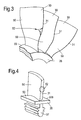
- the high pressure turbine comprises a turbine disc 28 and a plurality of circumferentially spaced radially extending turbine blades 30, as shown more clearly in figures 3 and 4 .
- the high pressure turbine also comprises a plurality of turbine vanes 32 positioned downstream of the turbine blades 30.
- Figure 2 shows three of the nozzle guide vanes 26 and in particular the leading edges 27 of the nozzle guide vanes 26.
- the nozzle guide vanes 26 have radially inner platforms 29A and radially outer platforms 29B.
- the nozzle guide vanes 26 are provided with a nickel aluminide coating 50 on the gas washed surfaces of the nozzle guide vanes 26 and the gas washed surfaces of the radially inner and radially outer platforms 29A and 29B.
- a damaged portion 52 of the nickel aluminide coating 50 is shown at the leading edge 27 of one of the nozzle guide vanes 26.
- FIG. 3 shows three turbine blades 30 and in particular the leading edges 31 of the turbine blades 30.
- the turbine blades 30 are integral with the turbine disc 28 to form a turbine blisk, turbine bling or turbine blum.
- the turbine disc 28 has a radially outer surface 33 located circumferentially between adjacent turbine blades 30.
- the turbine blades 30 are provided with a nickel aluminide coating 50 on the gas washed surfaces of the turbine blades 30 and the gas washed radially outer surface 33 of the turbine disc 28.
- a damaged portion 52 of the nickel aluminide coating 50 is shown at the leading edge 31 of one of the turbine blades 30.
- FIG 4 shows one turbine blade 30B and in particular the leading edge 31 of the turbine blade 30B.
- the turbine blade 30B is separate to the turbine disc 28.
- the turbine blade 30B comprises a radially inner platform 35 and a firtree root 37.
- the firtree root 37 of each turbine blade 30B is arranged to locate in a corresponding one of a plurality of correspondingly shaped firtree slots in the periphery of the turbine disc 28, as is well known to those skilled in the art.
- the turbine blades 30B are provided with a nickel aluminide coating 50 on the gas washed surfaces of the turbine blades 30 and the gas washed surfaces of the radially inner platform 35. A damaged portion 52 of the nickel aluminide coating 50 is shown at the leading edge 31 of one of the turbine blades 30B.
- Figure 5 shows a graph of aluminium concentration of a nickel aluminide coating on a gas turbine engine component versus depth with time. The graph shows that during service of a gas turbine engine component the concentration of aluminium changes. Initially in region A the concentration of aluminium may be up to 75at% at the surface of the nickel aluminide coating, but this much aluminium makes the nickel aluminide coating brittle. The concentration of aluminium reduces at a relatively fast rate with time in region A to reach region B. In region A the aluminium diffuses from the nickel aluminide coating to the substrate of the gas turbine engine component.
- region B chemically stable beta nickel aluminide coating forms, but aluminium again diffuses relatively slowly from the nickel aluminide coating to the substrate of the gas turbine engine component and the concentration of aluminium reduces relatively slowly.
- the concentration of aluminium reduces at a relatively fast rate with time in region C as aluminium diffuses from the nickel aluminide coating to the substrate of the gas turbine engine component.
- the aluminium in the nickel aluminide coating in region B acts as a reservoir of aluminium to provide the corrosion protection of the nickel aluminide coating.
- the following method is used. Initially the damaged portion 52 of the nickel aluminide coating 50 is removed from a portion 53 of the surface of the nozzle guide vane 26, or the turbine blade 30 or 30B, as shown in figure 6 . Any oxidised layer 54 is then removed from the portion 53 of the surface of the nozzle guide vane 26, or the turbine blade 30 or 30B, as shown in figure 6 . It is to be noted that part of the substrate is removed from the portion 53 of the surface of the nozzle guide vane 26, or turbine blade 30 or 30B.
- stoichiometric amounts of nickel and aluminium 55 are placed on the portion 53 of the surface of the nozzle guide vane 26, or turbine blade 30 or 30B, as shown in figure 7 .
- stoichiometric amounts of nickel and aluminium 55 are heat treated to form a nickel aluminide patch coating 50B on the portion 53 of the surface of the nozzle guide vane 26, or turbine blade 30 or 30B, and to bond the nickel aluminide patch coating 50B to the portion 53 of the surface of the nozzle guide vane 26, or turbine blade 30 or 30B, and to the nickel aluminide coating 50 adjacent to, or in some cases, surrounding the portion 53 of the surface of the nozzle guide vane 26, or turbine blade 30 or 30B, as shown in figure 8 .
- any excess nickel aluminide patch coating 50B may be necessary to remove any excess nickel aluminide patch coating 50B from the portion of the nozzle guide vane 26, or turbine blade 30 or 30B, if the repaired nickel aluminide patch coating 50B stands proud from the surface of the undamaged nickel aluminide coating 50 in order to regain an aerodynamic profile.
- the excess nickel aluminide patch coating 50B is removed by mechanical machining, e.g. grinding, or chemical machining, e.g. etching with an acid, electro-chemical machining using an electrolyte and the electrolyte may be an acid.
- the mechanical machining, chemical machining or electro-chemical machining may involve the use of agitation.
- the thickness of the nickel aluminide coating 50 may be up to 200 micrometres
- the thickness of the oxide layer 54 may be up to 200 micrometres
- the thickness of the nickel aluminide patch coating 50B may be up to 500 micrometres.
- the stoichiometric amounts of nickel and aluminium may be placed on the portion 53 of the surface of the nozzle guide vane 26, or turbine blade 30 or 30B, by supplying and placing a mixture of nickel and aluminium powders, or particles.
- the stoichiometric amounts of nickel and aluminium may be placed on the portion 53 of the surface of the nozzle guide vane 26, or turbine blade 30 or 30B, by supplying and placing nickel aluminide powder, or particles, on the portion 53 of the nozzle guide vane 26, or turbine blade 30 or 30B.
- the stoichiometric amounts of nickel and aluminium 55 are placed on the portion 53 of the surface of the nozzle guide vane 26, or turbine blade 30 or 30B, by placing at least one foil 57 on the portion 53 of the surface of the gas turbine engine component 26, 30 or 30B.
- the foil 57 comprises either pre-sintered nickel aluminide powder, or particles, or pre-sintered nickel and aluminium powder, or particles.
- the foil 57 is placed on the portion 53 of the surface of the gas turbine engine component 26, 30 or 30B by blowing the at least one foil 57 onto the portion 53 of the surface of the gas turbine engine component 26, 30 or 30B. It may be necessary to place a first foil 57 onto the portion 53 of the surface of the gas turbine engine component 26, 30 or 30B and placing at least one further foil 57 onto the first foil 57. It may be necessary to place a plurality of further foils 57B to 57F onto the first foil 57A and each further foil 57B to 57F is placed on a preceding foil 57 in order to build up the required thickness of nickel aluminide patch coating 50B.
- the number of foils 57 required depends upon the thickness of the foils 57 and the required thickness of the nickel aluminide patch coating 50B. It may be necessary to heat the foils 57 to aid the blowing of the foils 57 onto the portion 53 of the surface of the nozzle guide vane 26, or turbine blade 30 or 30B, and in particular hot gas is arranged to impinge upon the foil 57 to heat it and to form it against the portion 53 of the surface of the nozzle guide vane 26, or turbine blade 30 or 30B. The edges of the foil 57 are held against the nickel aluminide coating 50.
- FIG 7 shows hot gas jets H impinging on the foil 57 to heat it and to blow it onto the portion 53 of the surface of the nozzle guide vane 26, or turbine blade 30 or 30B.
- the hot gas jets H are provided by a heating device which comprises an enclosure which extends over the portion 53 to be repaired.
- the enclosure is made from steel or ceramic and the enclosure comprises nozzles to direct hot gas jets H onto the foil 57.
- the hot gas jets may be argon or other inert gas.
- the heating device locally heats the portion 53 to be repaired.
- the stoichiometric amounts of nickel and aluminium are heat treated using the heating device which provides hot gases jets H over the portion 53 to be repaired.
- the heating device locally heats the portion 53 to be repaired.
- the hot gas jets H sinter, consolidate and bond the nickel and aluminium to form the nickel aluminide patch coating 50B on the portion 53 to be repaired.
- the hot gas jets H provide impulses of heat into the surface of the nozzle guide vane 26 or turbine blade 30 or 30B.
- the hot gas jets H provide known quantities of gas, with known impulses of heat at a known rate into the surface of the nozzle guide vane 26 or turbine blade 30 or 30B to control the depth of heating into the surface of the nozzle guide vane 26 or turbine blade 30, 30B.
- the sintering may be at a temperature of about 1000°C to 1200°C for 1 to 6 hours and at a pressure of 4 to 5 bars, 0.4 to 0.5MPa.
- a laser beam, or other high energy beam is directed to impinge upon the periphery 60 of the nickel aluminide patch coating 50B and to move to the periphery 62 of the nickel aluminide coating 50 adjacent to, or surrounding, the nickel aluminide patch coating 50B.
- the laser beam or other high energy beam, is moved in a zig-zag pattern, or a cross-hatched pattern, P from the periphery 60 of the nickel aluminide patch coating 60 to the periphery 62 of the nickel aluminide coating 50 adjacent to, or surrounding, the nickel aluminide patch coating 50B and back throughout the full peripheries 60 and 62 of the nickel aluminide patch coating 50B and the nickel aluminide coating 50.
- the laser beam, or other high energy beam is moved in a pattern P such that the whole of the periphery of the nickel aluminide patch coating 50B and the whole of the periphery of the nickel aluminide coating 50 adjacent to, or surrounding the nickel aluminide patch coating 50B are heated uniformly to the same degree, or by the same amount.
- the laser beam, or other high energy beam produces repeatable process conditions to heat the whole of the periphery of the nickel aluminide patch coating 50B and the whole of the periphery of the nickel aluminide coating 50 adjacent to, or surround, the nickel aluminide patch coating 50B uniformly to the same degree, or by the same amount.
- the laser beam may be a pulsed laser beam which is pulsed at each point in its path or alternatively may be a continuous laser beam.
- a melting point depressant may be provided with the stoichiometric amounts of nickel and aluminium in order to aid sintering of the nickel and aluminium powder, or particles or the nickel aluminide powder or particles.
- the melting point depressant may be boron or copper.
- the melting point depressant may be provided as a coating on the powder, or particles, preferably by sputtering.
- the nickel aluminide powder, or particles may be provided with a halogen salt flux coating, preferably by sputtering.
- the stoichiometric amounts of nickel and aluminium means the amounts of nickel and aluminium required to produce beta nickel aluminide, NiAl.
- These stoichiometric amounts, or proportions, of nickel and aluminium provided are broadly 40 to 60at% nickel and 60 to 40at% aluminium, more preferably 45 to 55at% nickel and 55 to 45at% aluminium in particular 50at% nickel and 50at% aluminium, or 69wt% nickel and 31wt% aluminium, to produce NiAl.
- amounts of nickel and aluminium powder, or particles, are provided accordingly or nickel aluminide is prepared with these proportions of nickel and aluminium.
- a thin layer of nickel, and/or cobalt, up to 50 micrometres, may be provided to give inter-diffusion, on the portion of the surface of the gas turbine engine component prior to placing the stoichiometric amounts of nickel and aluminium to assist consolidation of the nickel aluminide patch coating.
- a thin layer, up to 50 micrometres, of aluminium may be provided on the portion of the surface of the gas turbine engine component prior to placing the stoichiometric amounts of nickel and aluminium to assist consolidation of the nickel aluminide patch coating.
- the damaged portion 52 of the nickel aluminide coating 50 is removed by mechanical machining, e.g. by grinding, or chemical stripping, e.g. etching with an acid, electro-chemical machining using an electrolyte and the electrolyte may be an acid.
- the mechanical machining, chemical machining or electro-chemical machining may involve the use of agitation.
- the oxide layer 54 is removed by mechanical machining, e.g. grinding.
- the nickel aluminide coating 50 may be provided with a mask before the damaged portion 52 is removed.
- the advantage of the present invention is that because the required stoichiometric amounts of nickel and aluminium are provided as powder, or particles, or as nickel aluminide the time required for heat treatment, diffusion, is reduced. Additionally, because the required stoichiometric amounts of nickel and aluminium are provided as powder, or particles, or as nickel aluminide the concentration of aluminium in the original nickel aluminide coating 50 would not increase and change it to the brittle phase NiAl 3 , the original undamaged nickel aluminide coating will not have a "halo" or "ring” with a high concentration of aluminium. Also, the stoichiometric amounts of nickel and aluminium provide optimum oxidation resistance.
- nickel and aluminium powders may be metered to control the thickness and composition of the nickel aluminide coating.
- the use of nickel aluminide powder may be metered to control the thickness of the nickel aluminide coating. It may be possible to dispense with the requirement to solution heat treat the gas turbine engine component following repair of the nickel aluminide coating.
- the present invention has been described with reference to a simple nickel aluminide coating which is repaired with stoichiometric amounts of nickel and aluminium.
- the present invention is also applicable to the repair of more complex aluminide coatings such as platinum aluminide coatings, chromium aluminide coatings or silicon aluminide coatings.
- platinum aluminide coating the repair would involve the use of stoichiometric amounts of nickel, platinum and aluminium again in the form of nickel, platinum and aluminium powders, beta platinum aluminide powder, foil of pre-sintered nickel, platinum and aluminium powders or a foil of pre-sintered beta platinum aluminide powder.
- These stoichiometric amounts, or proportions, of nickel, platinum and aluminium provided for a beta platinum aluminide are broadly more than 0at% up to 30at% nickel, 50 to 20at% platinum and 40 to 60at% aluminium, more preferably more than 0at% up to 25at% nickel, 25 to 50 at% platinum and 44 to 55at% aluminium.
- the preferred composition is 25at% nickel, 25at% platinum and 50at% aluminium, or 19wt% nickel, 63,5wt% platinum and 17.5wt% aluminium.
- a further composition is 30at% nickel, 30at% platinum and 40at% aluminium.
- Another composition is 20at% nickel, 20at% platinum and 60at% aluminium.
- amounts of nickel, platinum and aluminium powder, or particles, are provided accordingly or nickel/platinum aluminide is prepared with these proportions of nickel, platinum and aluminium.
- the present invention is also applicable to the repair of other coatings e.g. MCrAlY coatings, where M is one or more of Fe, Co or Ni, or abrasive coatings comprising cubic boron nitride, silicon nitride, silicon carbide, alumina or diamond grits in a metal matrix of cobalt or MCrAlY or wear resistant coatings comprising chromium carbide etc.
- M is one or more of Fe, Co or Ni
- abrasive coatings comprising cubic boron nitride, silicon nitride, silicon carbide, alumina or diamond grits in a metal matrix of cobalt or MCrAlY or wear resistant coatings comprising chromium carbide etc.
- the present invention has been described with reference to repairing coatings on gas turbine engine components, the present invention is also applicable to repairing coatings on other component or articles.
Landscapes
- Chemical & Material Sciences (AREA)
- Engineering & Computer Science (AREA)
- Mechanical Engineering (AREA)
- Chemical Kinetics & Catalysis (AREA)
- Materials Engineering (AREA)
- Metallurgy (AREA)
- Organic Chemistry (AREA)
- General Engineering & Computer Science (AREA)
- Turbine Rotor Nozzle Sealing (AREA)
- Application Of Or Painting With Fluid Materials (AREA)
Abstract
Description
- The present invention relates to a method of repairing a coating on an article and in particular to a method of locally repairing a coating on a gas turbine engine component.
- Gas turbine engine components, e.g. turbine blades, combustor nozzle guide vanes and turbine vanes, are generally provided with nickel aluminide coatings to provide high temperature oxidation resistance for the gas turbine engine components. In particular the gas turbine engine components comprise a nickel base superalloy substrate, which is provided with a nickel aluminide intermetallic coating. The nickel aluminide intermetallic coating is produced by depositing aluminium onto the surface of the nickel base superalloy substrate and inter-diffusing the aluminium and the nickel at the surface of the nickel base superalloy substrate, this process is known as aluminising. The aluminising process aims to produce a nickel aluminide intermetallic, a beta nickel aluminide NiAl. The aluminising process may be pack aluminising, slurry aluminising, out of pack vapour aluminising or chemical vapour deposition.
- However, after service in a gas turbine engine it is necessary to repair damaged gas turbine engine components, e.g. turbine blades, combustor nozzle guide vanes and turbine blades, to enable them to be re-used in the gas turbine engine.
- One method of repairing gas turbine engine components comprises removing all of the nickel aluminide coating from the gas turbine engine component, removing oxidation from the surface of the gas turbine engine component, repairing the gas turbine engine component and depositing a nickel aluminide coating on the gas turbine engine component. However, this method of repair is costly and time consuming and removes and replaces the nickel aluminide coating at portions of the gas turbine engine component where it is not necessary to remove the nickel aluminide coating.
- A further method of repairing gas turbine engine components comprises removing the nickel aluminide coating from a localised portion of the gas turbine engine component, removing oxidation from the localised portion of the surface of the gas turbine engine component, repairing the localised portion of the gas turbine engine component and depositing a nickel aluminide coating on the localised portion of the gas turbine engine component. The nickel aluminide is deposited locally by providing a tape of aluminium and a halogen salt flux and locally heating to aluminise the localised portion of the gas turbine engine component.
- A problem with the aluminising of a localised portion of the surface of the gas turbine engine component is that some of the aluminium may diffuse into the adjacent undamaged nickel aluminide coating. This additional aluminising of the adjacent undamaged nickel aluminide coating results in an increase in the concentration of aluminium in the undamaged nickel aluminide coating and this increases the risk of forming brittle aluminium rich phase, NiAl3. This over aluminising around the localised portion of the gas turbine engine component produces a "halo" or "ring" in the undamaged nickel aluminide coating which has a high aluminium concentration.
- Accordingly the present invention seeks to provide a novel method of locally repairing an aluminide coating on an article which reduces, preferably overcomes, the above mentioned problem.
- Accordingly the present invention provides a method of locally repairing a coating on an article comprising the steps of:-
- a) removing a damaged portion of a coating from a portion of the article,
- b) removing any oxidised layer from the portion of the article,
- c) placing material to form a patch coating on the portion of the article,
- d) heat treating the material to form a patch coating on the portion of the article and to bond the patch coating to the portion of the article and to the coating adjacent to the patch coating, and
- e) impinging a high energy beam on the coating and moving the high energy beam from the periphery of the patch coating to the periphery of the coating adjacent to the patch coating to uniformly heat the periphery of the patch coating and the periphery of the coating adjacent to the patch coating.
- Preferably the method comprises moving the high energy beam from the periphery of the patch coating to the periphery of the coating adjacent to the patch coating in a zig-zag pattern or moving the high energy beam from the periphery of the patch coating adjacent to the patch coating to the periphery of the coating to form a cross-hatch pattern.
- Preferably the high energy beam is a laser beam.
- The coating may comprise nickel aluminide and step c) comprises placing stoichiometric amounts of nickel and aluminium only to produce a nickel aluminide patch coating. Step c) may comprise placing stoichiometric amounts of nickel powder and aluminium powder on the portion of the article. Step c) may comprise placing nickel aluminide powder on the portion of the article.
Step c) may comprise placing at least one foil onto the portion of the article, the foil comprising pre-sintered nickel aluminide powder or pre-sintered nickel and aluminium powders. - Preferably step c) comprises placing 40 to 60at% nickel and 60 to 40at% aluminium to produce the nickel aluminide patch. More preferably step c) comprises placing 45 to 55at% nickel and 55 to 45at% aluminium to produce the nickel aluminide patch. In particular step c) comprises placing 50at% nickel and 50at% aluminium to form the nickel aluminide patch.
- Alternatively the coating may comprise platinum aluminide and step c) comprises placing stoichiometric amounts of platinum, nickel and aluminium to produce a platinum aluminide patch coating. Step c) may comprise placing stoichiometric amounts of platinum powder, nickel powder and aluminium powder on the portion of the article. Step c) may comprise placing platinum aluminide powder on the portion of the article. Step c) may comprise placing at least one foil onto the portion of the article, the foil comprising pre-sintered platinum aluminide powder or pre-sintered platinum, nickel and aluminium powders.
- Alternatively step c) comprises placing up to 30at% nickel, 50 to 20at% platinum and 40 to 60at% aluminium and 60 to 40at% aluminium to form the platinum aluminide patch. More preferably step c) comprises placing up to 25at% nickel, 25 to 50 at% platinum and 44 to 55at% aluminium to form the platinum aluminide patch. In particular step c) comprises placing 25at% nickel, 25at% platinum and 50at% aluminium to form the platinum aluminide patch.
- Step c) may comprise blowing the at least one foil onto the portion of the article.
- Step c) may comprise placing a first foil onto the portion of the article and placing at least one further foil onto the first foil.
- Step c) may comprise placing a plurality of further foils onto the first foil and each further foil is placed on a foil.
- Preferably step d) comprises locally heat treating the material to form the patch coating on the portion of the article and to bond the patch coating to the portion of the article and to the coating surrounding the patch coating.
- Preferably the local heat treating comprises providing a heating device, the heating device comprising an enclosure which extends over the portion of the article, the enclosure comprising nozzles to direct hot gas jets onto the portion of the article.
- Preferably the article comprises a gas turbine engine component.
- Preferably the gas turbine engine component comprises a turbine vane, a turbine blade, a combustor nozzle guide vane or a turbine blisk.
- The present invention will be more fully described by way of example with reference to the accompanying drawings in which:-
-
Figure 1 shows a turbofan gas turbine according having an article with a nickel aluminide coating repaired according to the present invention. -
Figure 2 is a perspective view of a combustor nozzle guide vane assembly with a nickel aluminide coating repaired according to the present invention. -
Figure 3 is a perspective view of a turbine blisk with a nickel aluminide coating repaired according to the present invention. -
Figure 4 is a perspective view of a turbine blade with a nickel aluminide coating repaired according to the present invention. -
Figure 5 is a graph of aluminium concentration in a nickel aluminide coating versus depth with time. -
Figure 6 is a cross-sectional view through a nickel aluminide coating after removal of a damaged portion of the nickel aluminide coating. -
Figure 7 is a cross-sectional view through a nickel aluminide coating after removal of a damaged portion of the nickel aluminide coating and a nickel aluminide foil for repairing the portion of the nickel aluminide coating. -
Figure 8 is a cross-sectional view through a nickel aluminide coating and a repaired portion of the nickel aluminide coating showing stitching of an interface between the nickel aluminide coating and the repaired portion of the nickel aluminide coating. -
Figure 9 is plan view of the nickel aluminide coating and the repaired portion of the nickel aluminide coating showing stitching of the interface between the nickel aluminide coating and the repaired portion of the nickel aluminide coating. - A turbofan
gas turbine engine 10, as shown infigure 1 , comprises in flow series anintake 12, afan section 14, acompressor section 16, acombustor section 18, aturbine section 20 and an exhaust 22. Thefan section 14 comprises a fan. Thecompressor section 16 comprises an intermediate pressure compressor and a high pressure compressor arranged in flow series. Theturbine section 20 comprises a high pressure turbine, an intermediate pressure turbine and a low pressure turbine arranged in flow series. The high pressure turbine is arranged to drive the high pressure compressor. The intermediate pressure turbine is arranged to drive the intermediate pressure compressor and the low pressure turbine is arranged to drive the fan in thefan section 14. - In operation air is compressed as it flows sequentially through the fan in the
fan section 14 and the intermediate pressure compressor and the high pressure compressor in thecompressor section 16. The compressed air is supplied to acombustor 24 in thecombustor section 18, where fuel is burnt to produce hot gases. The hot gases flow sequentially through the high pressure turbine, the intermediate pressure turbine and the low pressure turbine in theturbine section 20. - The
combustor 24 has a nozzleguide vane assembly 26, a portion of which is shown more clearly infigure 2 . The high pressure turbine comprises aturbine disc 28 and a plurality of circumferentially spaced radially extendingturbine blades 30, as shown more clearly infigures 3 and 4 . The high pressure turbine also comprises a plurality ofturbine vanes 32 positioned downstream of theturbine blades 30. -
Figure 2 shows three of thenozzle guide vanes 26 and in particular the leadingedges 27 of the nozzle guide vanes 26. Thenozzle guide vanes 26 have radiallyinner platforms 29A and radiallyouter platforms 29B. Thenozzle guide vanes 26 are provided with anickel aluminide coating 50 on the gas washed surfaces of thenozzle guide vanes 26 and the gas washed surfaces of the radially inner and radiallyouter platforms portion 52 of thenickel aluminide coating 50 is shown at theleading edge 27 of one of the nozzle guide vanes 26. -
Figure 3 shows threeturbine blades 30 and in particular the leadingedges 31 of theturbine blades 30. In this arrangement theturbine blades 30 are integral with theturbine disc 28 to form a turbine blisk, turbine bling or turbine blum. Theturbine disc 28 has a radiallyouter surface 33 located circumferentially betweenadjacent turbine blades 30. Theturbine blades 30 are provided with anickel aluminide coating 50 on the gas washed surfaces of theturbine blades 30 and the gas washed radiallyouter surface 33 of theturbine disc 28. A damagedportion 52 of thenickel aluminide coating 50 is shown at theleading edge 31 of one of theturbine blades 30. -
Figure 4 shows oneturbine blade 30B and in particular the leadingedge 31 of theturbine blade 30B. In this arrangement theturbine blade 30B is separate to theturbine disc 28. Theturbine blade 30B comprises a radiallyinner platform 35 and afirtree root 37. Thefirtree root 37 of eachturbine blade 30B is arranged to locate in a corresponding one of a plurality of correspondingly shaped firtree slots in the periphery of theturbine disc 28, as is well known to those skilled in the art. Theturbine blades 30B are provided with anickel aluminide coating 50 on the gas washed surfaces of theturbine blades 30 and the gas washed surfaces of the radiallyinner platform 35. A damagedportion 52 of thenickel aluminide coating 50 is shown at theleading edge 31 of one of theturbine blades 30B. -
Figure 5 shows a graph of aluminium concentration of a nickel aluminide coating on a gas turbine engine component versus depth with time. The graph shows that during service of a gas turbine engine component the concentration of aluminium changes. Initially in region A the concentration of aluminium may be up to 75at% at the surface of the nickel aluminide coating, but this much aluminium makes the nickel aluminide coating brittle. The concentration of aluminium reduces at a relatively fast rate with time in region A to reach region B. In region A the aluminium diffuses from the nickel aluminide coating to the substrate of the gas turbine engine component. In region B chemically stable beta nickel aluminide coating forms, but aluminium again diffuses relatively slowly from the nickel aluminide coating to the substrate of the gas turbine engine component and the concentration of aluminium reduces relatively slowly. The concentration of aluminium reduces at a relatively fast rate with time in region C as aluminium diffuses from the nickel aluminide coating to the substrate of the gas turbine engine component. The aluminium in the nickel aluminide coating in region B acts as a reservoir of aluminium to provide the corrosion protection of the nickel aluminide coating. However, there must be a useful depth of the nickel aluminide coating. A problem arises when it is necessary to repair a nickel aluminide coating in that the thickness of the nickel aluminide coating is not known and the composition of the nickel aluminide coating is not known, the position of the nickel aluminide coating relative tofigure 5 is not known, e.g. whether the nickel aluminide coating is in region B or region C or if the nickel aluminide coating is in region B the position in region B. - In order to locally repair the damaged
portion 52 of thenickel aluminide coating 50 on thenozzle guide vane 26, or theturbine blade figures 6 to 10 , is used. Initially the damagedportion 52 of thenickel aluminide coating 50 is removed from aportion 53 of the surface of thenozzle guide vane 26, or theturbine blade figure 6 . Anyoxidised layer 54 is then removed from theportion 53 of the surface of thenozzle guide vane 26, or theturbine blade figure 6 . It is to be noted that part of the substrate is removed from theportion 53 of the surface of thenozzle guide vane 26, orturbine blade aluminium 55 are placed on theportion 53 of the surface of thenozzle guide vane 26, orturbine blade figure 7 . Then stoichiometric amounts of nickel andaluminium 55 are heat treated to form a nickelaluminide patch coating 50B on theportion 53 of the surface of thenozzle guide vane 26, orturbine blade aluminide patch coating 50B to theportion 53 of the surface of thenozzle guide vane 26, orturbine blade nickel aluminide coating 50 adjacent to, or in some cases, surrounding theportion 53 of the surface of thenozzle guide vane 26, orturbine blade figure 8 . - It may be necessary to remove any excess nickel
aluminide patch coating 50B from the portion of thenozzle guide vane 26, orturbine blade aluminide patch coating 50B stands proud from the surface of the undamagednickel aluminide coating 50 in order to regain an aerodynamic profile. The excess nickelaluminide patch coating 50B is removed by mechanical machining, e.g. grinding, or chemical machining, e.g. etching with an acid, electro-chemical machining using an electrolyte and the electrolyte may be an acid. The mechanical machining, chemical machining or electro-chemical machining may involve the use of agitation. - As shown in
figure 6 the thickness of thenickel aluminide coating 50 may be up to 200 micrometres, the thickness of theoxide layer 54 may be up to 200 micrometres and the thickness of the nickelaluminide patch coating 50B may be up to 500 micrometres. - The stoichiometric amounts of nickel and aluminium may be placed on the
portion 53 of the surface of thenozzle guide vane 26, orturbine blade portion 53 of the surface of thenozzle guide vane 26, orturbine blade portion 53 of thenozzle guide vane 26, orturbine blade - Alternatively, as shown in
figure 7 , the stoichiometric amounts of nickel andaluminium 55 are placed on theportion 53 of the surface of thenozzle guide vane 26, orturbine blade foil 57 on theportion 53 of the surface of the gasturbine engine component foil 57 comprises either pre-sintered nickel aluminide powder, or particles, or pre-sintered nickel and aluminium powder, or particles. - The
foil 57 is placed on theportion 53 of the surface of the gasturbine engine component foil 57 onto theportion 53 of the surface of the gasturbine engine component first foil 57 onto theportion 53 of the surface of the gasturbine engine component further foil 57 onto thefirst foil 57. It may be necessary to place a plurality offurther foils 57B to 57F onto thefirst foil 57A and eachfurther foil 57B to 57F is placed on a precedingfoil 57 in order to build up the required thickness of nickelaluminide patch coating 50B. The number offoils 57 required depends upon the thickness of thefoils 57 and the required thickness of the nickelaluminide patch coating 50B. It may be necessary to heat thefoils 57 to aid the blowing of thefoils 57 onto theportion 53 of the surface of thenozzle guide vane 26, orturbine blade foil 57 to heat it and to form it against theportion 53 of the surface of thenozzle guide vane 26, orturbine blade foil 57 are held against thenickel aluminide coating 50. In particularfigure 7 shows hot gas jets H impinging on thefoil 57 to heat it and to blow it onto theportion 53 of the surface of thenozzle guide vane 26, orturbine blade portion 53 to be repaired. The enclosure is made from steel or ceramic and the enclosure comprises nozzles to direct hot gas jets H onto thefoil 57. The hot gas jets may be argon or other inert gas. The heating device locally heats theportion 53 to be repaired. - The stoichiometric amounts of nickel and aluminium are heat treated using the heating device which provides hot gases jets H over the
portion 53 to be repaired. The heating device locally heats theportion 53 to be repaired. The hot gas jets H sinter, consolidate and bond the nickel and aluminium to form the nickelaluminide patch coating 50B on theportion 53 to be repaired. The hot gas jets H provide impulses of heat into the surface of thenozzle guide vane 26 orturbine blade nozzle guide vane 26 orturbine blade nozzle guide vane 26 orturbine blade - Following consolidation and sintering a laser beam, or other high energy beam, is directed to impinge upon the
periphery 60 of the nickelaluminide patch coating 50B and to move to theperiphery 62 of thenickel aluminide coating 50 adjacent to, or surrounding, the nickelaluminide patch coating 50B. The laser beam, or other high energy beam, is moved in a zig-zag pattern, or a cross-hatched pattern, P from theperiphery 60 of the nickelaluminide patch coating 60 to theperiphery 62 of thenickel aluminide coating 50 adjacent to, or surrounding, the nickelaluminide patch coating 50B and back throughout thefull peripheries aluminide patch coating 50B and thenickel aluminide coating 50. Preferably there are up to five passes of the laser beam at each position on theperipheries aluminide patch coating 50B and the whole of the periphery of thenickel aluminide coating 50 adjacent to, or surrounding the nickelaluminide patch coating 50B are heated uniformly to the same degree, or by the same amount. Thus, the laser beam, or other high energy beam, produces repeatable process conditions to heat the whole of the periphery of the nickelaluminide patch coating 50B and the whole of the periphery of thenickel aluminide coating 50 adjacent to, or surround, the nickelaluminide patch coating 50B uniformly to the same degree, or by the same amount. The laser beam may be a pulsed laser beam which is pulsed at each point in its path or alternatively may be a continuous laser beam. - A melting point depressant may be provided with the stoichiometric amounts of nickel and aluminium in order to aid sintering of the nickel and aluminium powder, or particles or the nickel aluminide powder or particles. The melting point depressant may be boron or copper. The melting point depressant may be provided as a coating on the powder, or particles, preferably by sputtering.
- The nickel aluminide powder, or particles, may be provided with a halogen salt flux coating, preferably by sputtering.
- As mentioned here the stoichiometric amounts of nickel and aluminium means the amounts of nickel and aluminium required to produce beta nickel aluminide, NiAl. These stoichiometric amounts, or proportions, of nickel and aluminium provided are broadly 40 to 60at% nickel and 60 to 40at% aluminium, more preferably 45 to 55at% nickel and 55 to 45at% aluminium in particular 50at% nickel and 50at% aluminium, or 69wt% nickel and 31wt% aluminium, to produce NiAl. Thus amounts of nickel and aluminium powder, or particles, are provided accordingly or nickel aluminide is prepared with these proportions of nickel and aluminium.
- A thin layer of nickel, and/or cobalt, up to 50 micrometres, may be provided to give inter-diffusion, on the portion of the surface of the gas turbine engine component prior to placing the stoichiometric amounts of nickel and aluminium to assist consolidation of the nickel aluminide patch coating. A thin layer, up to 50 micrometres, of aluminium may be provided on the portion of the surface of the gas turbine engine component prior to placing the stoichiometric amounts of nickel and aluminium to assist consolidation of the nickel aluminide patch coating.
- The damaged
portion 52 of thenickel aluminide coating 50 is removed by mechanical machining, e.g. by grinding, or chemical stripping, e.g. etching with an acid, electro-chemical machining using an electrolyte and the electrolyte may be an acid. The mechanical machining, chemical machining or electro-chemical machining may involve the use of agitation. Theoxide layer 54 is removed by mechanical machining, e.g. grinding. - The
nickel aluminide coating 50 may be provided with a mask before the damagedportion 52 is removed. - It may be possible to add small amounts of yttrium and/or lanthanum to the stoichiometric amounts of nickel and aluminium to increase oxidation resistance. It may be possible to add chromium and silicon to increase oxidation and/or corrosion resistance.
- The advantage of the present invention is that because the required stoichiometric amounts of nickel and aluminium are provided as powder, or particles, or as nickel aluminide the time required for heat treatment, diffusion, is reduced. Additionally, because the required stoichiometric amounts of nickel and aluminium are provided as powder, or particles, or as nickel aluminide the concentration of aluminium in the original
nickel aluminide coating 50 would not increase and change it to the brittle phase NiAl3, the original undamaged nickel aluminide coating will not have a "halo" or "ring" with a high concentration of aluminium. Also, the stoichiometric amounts of nickel and aluminium provide optimum oxidation resistance. The use of nickel and aluminium powders may be metered to control the thickness and composition of the nickel aluminide coating. The use of nickel aluminide powder may be metered to control the thickness of the nickel aluminide coating. It may be possible to dispense with the requirement to solution heat treat the gas turbine engine component following repair of the nickel aluminide coating. - The present invention has been described with reference to a simple nickel aluminide coating which is repaired with stoichiometric amounts of nickel and aluminium. The present invention is also applicable to the repair of more complex aluminide coatings such as platinum aluminide coatings, chromium aluminide coatings or silicon aluminide coatings. In the case of a platinum aluminide coating the repair would involve the use of stoichiometric amounts of nickel, platinum and aluminium again in the form of nickel, platinum and aluminium powders, beta platinum aluminide powder, foil of pre-sintered nickel, platinum and aluminium powders or a foil of pre-sintered beta platinum aluminide powder.
- These stoichiometric amounts, or proportions, of nickel, platinum and aluminium provided for a beta platinum aluminide are broadly more than 0at% up to 30at% nickel, 50 to 20at% platinum and 40 to 60at% aluminium, more preferably more than 0at% up to 25at% nickel, 25 to 50 at% platinum and 44 to 55at% aluminium. In particular the preferred composition is 25at% nickel, 25at% platinum and 50at% aluminium, or 19wt% nickel, 63,5wt% platinum and 17.5wt% aluminium. A further composition is 30at% nickel, 30at% platinum and 40at% aluminium. Another composition is 20at% nickel, 20at% platinum and 60at% aluminium. Thus amounts of nickel, platinum and aluminium powder, or particles, are provided accordingly or nickel/platinum aluminide is prepared with these proportions of nickel, platinum and aluminium.
- The present invention is also applicable to the repair of other coatings e.g. MCrAlY coatings, where M is one or more of Fe, Co or Ni, or abrasive coatings comprising cubic boron nitride, silicon nitride, silicon carbide, alumina or diamond grits in a metal matrix of cobalt or MCrAlY or wear resistant coatings comprising chromium carbide etc.
- Although the present invention has been described with reference to repairing coatings on gas turbine engine components, the present invention is also applicable to repairing coatings on other component or articles.
Claims (15)
- A method of locally repairing a coating (50) on an article (26,30,30B) comprising the steps of:-a) removing a damaged portion of a coating (30) from a portion (53) of the article (26,30,30B),b) removing any oxidised layer (54) from the portion (53) of the article (26,30,30B),c) placing material (55) to form a patch coating (50B) on the portion (53) of the article (26,30,30B),d) heat treating the material (55) to form a patch coating (50B) on the portion (53) of the article (26,30,30B) and to bond the patch coating (50B) to the portion (53) of the article (26,30,30B) and to the coating (50) adjacent to the patch coating (50B), ande) impinging a high energy beam on the coating (50) and moving the high energy beam from the periphery (60) of the patch coating (50B) to the periphery (62) of the coating (50) adjacent to the patch coating (50B) to uniformly heat the periphery (60) of the patch coating (50B) and the periphery (62) of the coating (50) adjacent to the patch coating 50B).
- A method as claimed in claim 1 comprising moving the high energy beam from the periphery (60) of the patch coating (50B) to the periphery (62) of the coating (50) adjacent to the patch ocating (50B) in a zig-zag pattern (P) or moving the high energy beam from the periphery (60) adjacent to the patch coating (50B) of the patch coating (50B) to the periphery (62) of the coating (50) to form a cross-hatch pattern (P).
- A method as claimed in claim 1 or claim 2 wherein the high energy beam is a laser beam.
- A method as claimed in claim 1, claim 2 or claim 3 wherein the coating (50) comprises nickel aluminide and step c) comprises placing stoichiometric amounts of nickel and aluminium (55) only to produce a nickel aluminide patch coating (50B).
- A method as claimed in claim 4 wherein step c) comprises placing stoichiometric amounts of nickel powder and aluminium powder on the portion (53) of the article (26,30,30B) or step c) comprises placing nickel aluminide powder on the portion (53) of the article (26,30,30B).
- A method as claimed in claim 4 wherein step c) comprises placing at least one foil (57) onto the portion (53) of the article (26,30,30B), the foil (57) comprising pre-sintered nickel aluminide powder or pre-sintered nickel and aluminium powders.
- A method as claimed in claim 1, claim 2 or claim 3 wherein the coating (50) comprises platinum aluminide and step c) comprises placing stoichiometric amounts of platinum, nickel and aluminium to produce a platinum aluminide patch coating (50B).
- A method as claimed in claim 7 wherein step c) comprises placing stoichiometric amounts of platinum powder, nickel powder and aluminium powder on the portion (53) of the article (26,30,30B) or step c) comprises placing platinum aluminide powder on the portion (53) of the article (26,30,30B).
- A method as claimed in claim 7 wherein step c) comprises placing at least one foil (57) onto the portion (53) of the article (26,30,30B), the foil (57) comprising pre-sintered platinum aluminide powder or pre-sintered platinum, nickel and aluminium powders.
- A method as claimed in claim 6 or claim 9 wherein step c) comprises blowing the at least one foil (57) onto the portion (53) of the article (26,30,30B).
- A method as claimed in claim 10 wherein step c) comprises placing a first foil (57A) onto the portion (53) of the article (26,30,30B) and placing at least one further foil (57B,57C,57D,57E,57F) onto the first foil (57A).
- A method as claimed in any of claims 1 to 11 wherein step d) comprises locally heat treating the material (55) to form the patch coating (50B) on the portion (53) of the article (26,30,30B) and to bond the patch coating (50B) to the portion (53) of the article (26,30,30B) and to the coating (50) adjacent to surrounding the patch coating (50B).
- A method as claimed in claim 12 wherein locally heat treating comprises providing an enclosure which extends over the portion of the article (26,30,30B), through nozzles in the enclosure directing hot gas jets (H) onto the portion (53) of the article ((26,30,30B).
- A method as claimed in any of claims 1 to 13 wherein the article (26,30,30B) comprises a gas turbine engine (10) component.
- A method as claimed in claim 14 wherein the gas turbine engine (10) component comprises a turbine vane (26), a turbine blade (30B), a combustor nozzle guide vane or a turbine blisk (30).
Applications Claiming Priority (1)
| Application Number | Priority Date | Filing Date | Title |
|---|---|---|---|
| GBGB0816257.0A GB0816257D0 (en) | 2008-09-08 | 2008-09-08 | A method of repairing a coating on an article |
Publications (3)
| Publication Number | Publication Date |
|---|---|
| EP2179816A2 true EP2179816A2 (en) | 2010-04-28 |
| EP2179816A3 EP2179816A3 (en) | 2010-12-08 |
| EP2179816B1 EP2179816B1 (en) | 2018-04-04 |
Family
ID=39888877
Family Applications (1)
| Application Number | Title | Priority Date | Filing Date |
|---|---|---|---|
| EP09251899.2A Not-in-force EP2179816B1 (en) | 2008-09-08 | 2009-07-29 | A method of repairing a coating on an article |
Country Status (3)
| Country | Link |
|---|---|
| US (1) | US8496990B2 (en) |
| EP (1) | EP2179816B1 (en) |
| GB (1) | GB0816257D0 (en) |
Cited By (3)
| Publication number | Priority date | Publication date | Assignee | Title |
|---|---|---|---|---|
| EP2361999A1 (en) * | 2010-02-25 | 2011-08-31 | United Technologies Corporation | Repair of a coating on a turbine component |
| RU2718793C1 (en) * | 2019-03-05 | 2020-04-14 | Евгений Викторович Харанжевский | Method of obtaining super-hard wear-resistant coatings with low friction coefficient |
| US11686208B2 (en) | 2020-02-06 | 2023-06-27 | Rolls-Royce Corporation | Abrasive coating for high-temperature mechanical systems |
Families Citing this family (11)
| Publication number | Priority date | Publication date | Assignee | Title |
|---|---|---|---|---|
| US9056443B2 (en) * | 2013-02-04 | 2015-06-16 | General Electric Company | Brazing process, braze arrangement, and brazed article |
| WO2014143224A1 (en) | 2013-03-15 | 2014-09-18 | United Technologies Corporation | Turbine engine repair methods |
| US9334806B2 (en) * | 2013-09-05 | 2016-05-10 | General Electric Company | Methods for manufacturing an additively manufactured fuel contacting component to facilitate reducing coke formation |
| WO2016045043A1 (en) * | 2014-09-25 | 2016-03-31 | General Electric Company | Method for selective aluminide diffusion coating removal |
| US10030298B2 (en) | 2015-08-21 | 2018-07-24 | General Electric Company | Method for altering metal surfaces |
| US20170167288A1 (en) * | 2015-12-10 | 2017-06-15 | General Electric Company | Methods for modifying components |
| PL416283A1 (en) * | 2016-02-26 | 2017-08-28 | General Electric Company | Product with improved system of coatings and methods to produce it |
| EP3216554B1 (en) * | 2016-03-09 | 2020-05-06 | MTU Aero Engines GmbH | Component with wear- resistant openings and depressions and method for producing the same |
| US10717166B2 (en) | 2016-12-02 | 2020-07-21 | General Electric Company | Motorized apparatus for use with rotary machines |
| US10494926B2 (en) | 2017-08-28 | 2019-12-03 | General Electric Company | System and method for maintaining machines |
| CN117626258A (en) * | 2023-11-29 | 2024-03-01 | 中国科学院金属研究所 | Preparation method of platinum aluminum coating, platinum aluminum coating, single crystal high temperature alloy |
Citations (2)
| Publication number | Priority date | Publication date | Assignee | Title |
|---|---|---|---|---|
| EP1304446A1 (en) | 2001-10-22 | 2003-04-23 | General Electric Company | Method for replacing a damaged TBC ceramic layer |
| DE102006028297A1 (en) | 2006-06-20 | 2007-12-27 | Mtu Aero Engines Gmbh | Method of repairing inlet coverings |
Family Cites Families (9)
| Publication number | Priority date | Publication date | Assignee | Title |
|---|---|---|---|---|
| IL45597A (en) | 1974-03-01 | 1977-12-30 | Gen Electric | Tape for aluminide diffusion coating of metallic articles |
| DE19906765A1 (en) | 1999-02-17 | 2000-08-24 | Euromat Gmbh | Protective coating or repair, e.g. of pipeline, turbine blade, engine part, glass molding part or tool, is carried out by thermal bonding of pressed metal powder strip |
| DK1214458T3 (en) * | 1999-09-02 | 2004-07-12 | Leibniz Inst Fuer Festkoerper | Process for making solid amorphous layers on solid metallic moldings |
| US6387527B1 (en) * | 1999-10-04 | 2002-05-14 | General Electric Company | Method of applying a bond coating and a thermal barrier coating on a metal substrate, and related articles |
| US6560870B2 (en) * | 2001-05-08 | 2003-05-13 | General Electric Company | Method for applying diffusion aluminide coating on a selective area of a turbine engine component |
| US6730179B2 (en) | 2001-08-31 | 2004-05-04 | Sermatech International Inc. | Method for producing local aluminide coating |
| DE10357535A1 (en) | 2003-12-10 | 2005-07-07 | Mtu Aero Engines Gmbh | Ceramic material and method for repairing thermal barrier coatings with local damage |
| US7357958B2 (en) * | 2004-10-29 | 2008-04-15 | General Electric Company | Methods for depositing gamma-prime nickel aluminide coatings |
| ATE423892T1 (en) | 2006-07-17 | 2009-03-15 | Gen Electric | REPAIR PROCEDURES FOR COATED ITEMS |
-
2008
- 2008-09-08 GB GBGB0816257.0A patent/GB0816257D0/en not_active Ceased
-
2009
- 2009-07-29 US US12/461,017 patent/US8496990B2/en not_active Expired - Fee Related
- 2009-07-29 EP EP09251899.2A patent/EP2179816B1/en not_active Not-in-force
Patent Citations (2)
| Publication number | Priority date | Publication date | Assignee | Title |
|---|---|---|---|---|
| EP1304446A1 (en) | 2001-10-22 | 2003-04-23 | General Electric Company | Method for replacing a damaged TBC ceramic layer |
| DE102006028297A1 (en) | 2006-06-20 | 2007-12-27 | Mtu Aero Engines Gmbh | Method of repairing inlet coverings |
Cited By (3)
| Publication number | Priority date | Publication date | Assignee | Title |
|---|---|---|---|---|
| EP2361999A1 (en) * | 2010-02-25 | 2011-08-31 | United Technologies Corporation | Repair of a coating on a turbine component |
| RU2718793C1 (en) * | 2019-03-05 | 2020-04-14 | Евгений Викторович Харанжевский | Method of obtaining super-hard wear-resistant coatings with low friction coefficient |
| US11686208B2 (en) | 2020-02-06 | 2023-06-27 | Rolls-Royce Corporation | Abrasive coating for high-temperature mechanical systems |
Also Published As
| Publication number | Publication date |
|---|---|
| EP2179816A3 (en) | 2010-12-08 |
| US20100062180A1 (en) | 2010-03-11 |
| EP2179816B1 (en) | 2018-04-04 |
| GB0816257D0 (en) | 2008-10-15 |
| US8496990B2 (en) | 2013-07-30 |
Similar Documents
| Publication | Publication Date | Title |
|---|---|---|
| EP2179816B1 (en) | A method of repairing a coating on an article | |
| EP2182092B1 (en) | A method of repairing an aluminide coating on an article | |
| EP1512839B1 (en) | Method for creating an aluminide or chromide coating of turbine engine rotor component | |
| EP0861919B1 (en) | Method for removal of surface layers of metallic coatings (stripping) | |
| US9039917B2 (en) | Methods for manufacturing components from articles formed by additive-manufacturing processes | |
| EP1685923B1 (en) | Repair and reclassification of superalloy components | |
| EP1403395B1 (en) | Method for vapor phase aluminiding of a gas turbine blade partially masked with a masking enclosure | |
| EP1304446A1 (en) | Method for replacing a damaged TBC ceramic layer | |
| EP1236812B1 (en) | Method for refurbishing a coating including a thermally grown oxide | |
| US11090770B2 (en) | Method of forming a component | |
| WO2000017490A2 (en) | Methods for repairing and reclassifying airfoil parts | |
| US20160199930A1 (en) | Combined braze and coating method for fabrication and repair of mechanical components | |
| US6532657B1 (en) | Pre-service oxidation of gas turbine disks and seals | |
| JP7193617B2 (en) | Advance preparation for service runs and gas turbine component repairs | |
| US20070170150A1 (en) | Process for removing a layer | |
| US7140952B1 (en) | Oxidation protected blade and method of manufacturing | |
| US7387814B2 (en) | Process for in situ coating of turbo-machine components | |
| US20040018299A1 (en) | Method of forming a diffusion coating on the surface of a workpiece | |
| US9562436B2 (en) | Components with micro cooled patterned coating layer and methods of manufacture | |
| EP1918411A2 (en) | Coated turbine engine components and methods for making the same | |
| EP1076108B1 (en) | Process for treating the surface of a component, made from a Ni based superalloy, to be coated | |
| WO2018226219A1 (en) | Methods for structural repair of industrial machine components | |
| Kempster et al. | A novel method for refurbishing used hot section gas turbine blades |
Legal Events
| Date | Code | Title | Description |
|---|---|---|---|
| PUAI | Public reference made under article 153(3) epc to a published international application that has entered the european phase |
Free format text: ORIGINAL CODE: 0009012 |
|
| AK | Designated contracting states |
Kind code of ref document: A2 Designated state(s): AT BE BG CH CY CZ DE DK EE ES FI FR GB GR HR HU IE IS IT LI LT LU LV MC MK MT NL NO PL PT RO SE SI SK SM TR |
|
| AX | Request for extension of the european patent |
Extension state: AL BA RS |
|
| PUAL | Search report despatched |
Free format text: ORIGINAL CODE: 0009013 |
|
| AK | Designated contracting states |
Kind code of ref document: A3 Designated state(s): AT BE BG CH CY CZ DE DK EE ES FI FR GB GR HR HU IE IS IT LI LT LU LV MC MK MT NL NO PL PT RO SE SI SK SM TR |
|
| AX | Request for extension of the european patent |
Extension state: AL BA RS |
|
| RIC1 | Information provided on ipc code assigned before grant |
Ipc: C23C 10/00 20060101ALN20101101BHEP Ipc: F01D 5/00 20060101ALI20101101BHEP Ipc: B23P 6/00 20060101AFI20100318BHEP |
|
| 17P | Request for examination filed |
Effective date: 20110524 |
|
| RAP1 | Party data changed (applicant data changed or rights of an application transferred) |
Owner name: ROLLS-ROYCE PLC |
|
| STAA | Information on the status of an ep patent application or granted ep patent |
Free format text: STATUS: EXAMINATION IS IN PROGRESS |
|
| 17Q | First examination report despatched |
Effective date: 20161114 |
|
| RIC1 | Information provided on ipc code assigned before grant |
Ipc: C23C 10/60 20060101ALI20170926BHEP Ipc: C23C 10/52 20060101ALI20170926BHEP Ipc: F01D 5/00 20060101ALI20170926BHEP Ipc: B23P 6/00 20060101AFI20170926BHEP Ipc: C23C 24/08 20060101ALI20170926BHEP |
|
| GRAP | Despatch of communication of intention to grant a patent |
Free format text: ORIGINAL CODE: EPIDOSNIGR1 |
|
| STAA | Information on the status of an ep patent application or granted ep patent |
Free format text: STATUS: GRANT OF PATENT IS INTENDED |
|
| INTG | Intention to grant announced |
Effective date: 20171116 |
|
| GRAS | Grant fee paid |
Free format text: ORIGINAL CODE: EPIDOSNIGR3 |
|
| GRAA | (expected) grant |
Free format text: ORIGINAL CODE: 0009210 |
|
| STAA | Information on the status of an ep patent application or granted ep patent |
Free format text: STATUS: THE PATENT HAS BEEN GRANTED |
|
| AK | Designated contracting states |
Kind code of ref document: B1 Designated state(s): AT BE BG CH CY CZ DE DK EE ES FI FR GB GR HR HU IE IS IT LI LT LU LV MC MK MT NL NO PL PT RO SE SI SK SM TR |
|
| REG | Reference to a national code |
Ref country code: GB Ref legal event code: FG4D |
|
| REG | Reference to a national code |
Ref country code: CH Ref legal event code: EP |
|
| REG | Reference to a national code |
Ref country code: AT Ref legal event code: REF Ref document number: 985081 Country of ref document: AT Kind code of ref document: T Effective date: 20180415 |
|
| REG | Reference to a national code |
Ref country code: DE Ref legal event code: R096 Ref document number: 602009051585 Country of ref document: DE |
|
| REG | Reference to a national code |
Ref country code: IE Ref legal event code: FG4D |
|
| REG | Reference to a national code |
Ref country code: FR Ref legal event code: PLFP Year of fee payment: 10 |
|
| REG | Reference to a national code |
Ref country code: NL Ref legal event code: MP Effective date: 20180404 |
|
| REG | Reference to a national code |
Ref country code: LT Ref legal event code: MG4D |
|
| PG25 | Lapsed in a contracting state [announced via postgrant information from national office to epo] |
Ref country code: NL Free format text: LAPSE BECAUSE OF FAILURE TO SUBMIT A TRANSLATION OF THE DESCRIPTION OR TO PAY THE FEE WITHIN THE PRESCRIBED TIME-LIMIT Effective date: 20180404 |
|
| PG25 | Lapsed in a contracting state [announced via postgrant information from national office to epo] |
Ref country code: LT Free format text: LAPSE BECAUSE OF FAILURE TO SUBMIT A TRANSLATION OF THE DESCRIPTION OR TO PAY THE FEE WITHIN THE PRESCRIBED TIME-LIMIT Effective date: 20180404 Ref country code: PL Free format text: LAPSE BECAUSE OF FAILURE TO SUBMIT A TRANSLATION OF THE DESCRIPTION OR TO PAY THE FEE WITHIN THE PRESCRIBED TIME-LIMIT Effective date: 20180404 Ref country code: SE Free format text: LAPSE BECAUSE OF FAILURE TO SUBMIT A TRANSLATION OF THE DESCRIPTION OR TO PAY THE FEE WITHIN THE PRESCRIBED TIME-LIMIT Effective date: 20180404 Ref country code: BG Free format text: LAPSE BECAUSE OF FAILURE TO SUBMIT A TRANSLATION OF THE DESCRIPTION OR TO PAY THE FEE WITHIN THE PRESCRIBED TIME-LIMIT Effective date: 20180704 Ref country code: NO Free format text: LAPSE BECAUSE OF FAILURE TO SUBMIT A TRANSLATION OF THE DESCRIPTION OR TO PAY THE FEE WITHIN THE PRESCRIBED TIME-LIMIT Effective date: 20180704 Ref country code: FI Free format text: LAPSE BECAUSE OF FAILURE TO SUBMIT A TRANSLATION OF THE DESCRIPTION OR TO PAY THE FEE WITHIN THE PRESCRIBED TIME-LIMIT Effective date: 20180404 Ref country code: ES Free format text: LAPSE BECAUSE OF FAILURE TO SUBMIT A TRANSLATION OF THE DESCRIPTION OR TO PAY THE FEE WITHIN THE PRESCRIBED TIME-LIMIT Effective date: 20180404 |
|
| PG25 | Lapsed in a contracting state [announced via postgrant information from national office to epo] |
Ref country code: GR Free format text: LAPSE BECAUSE OF FAILURE TO SUBMIT A TRANSLATION OF THE DESCRIPTION OR TO PAY THE FEE WITHIN THE PRESCRIBED TIME-LIMIT Effective date: 20180705 Ref country code: HR Free format text: LAPSE BECAUSE OF FAILURE TO SUBMIT A TRANSLATION OF THE DESCRIPTION OR TO PAY THE FEE WITHIN THE PRESCRIBED TIME-LIMIT Effective date: 20180404 Ref country code: LV Free format text: LAPSE BECAUSE OF FAILURE TO SUBMIT A TRANSLATION OF THE DESCRIPTION OR TO PAY THE FEE WITHIN THE PRESCRIBED TIME-LIMIT Effective date: 20180404 |
|
| REG | Reference to a national code |
Ref country code: AT Ref legal event code: MK05 Ref document number: 985081 Country of ref document: AT Kind code of ref document: T Effective date: 20180404 |
|
| PG25 | Lapsed in a contracting state [announced via postgrant information from national office to epo] |
Ref country code: PT Free format text: LAPSE BECAUSE OF FAILURE TO SUBMIT A TRANSLATION OF THE DESCRIPTION OR TO PAY THE FEE WITHIN THE PRESCRIBED TIME-LIMIT Effective date: 20180806 |
|
| REG | Reference to a national code |
Ref country code: DE Ref legal event code: R097 Ref document number: 602009051585 Country of ref document: DE |
|
| PG25 | Lapsed in a contracting state [announced via postgrant information from national office to epo] |
Ref country code: DK Free format text: LAPSE BECAUSE OF FAILURE TO SUBMIT A TRANSLATION OF THE DESCRIPTION OR TO PAY THE FEE WITHIN THE PRESCRIBED TIME-LIMIT Effective date: 20180404 Ref country code: EE Free format text: LAPSE BECAUSE OF FAILURE TO SUBMIT A TRANSLATION OF THE DESCRIPTION OR TO PAY THE FEE WITHIN THE PRESCRIBED TIME-LIMIT Effective date: 20180404 Ref country code: AT Free format text: LAPSE BECAUSE OF FAILURE TO SUBMIT A TRANSLATION OF THE DESCRIPTION OR TO PAY THE FEE WITHIN THE PRESCRIBED TIME-LIMIT Effective date: 20180404 Ref country code: RO Free format text: LAPSE BECAUSE OF FAILURE TO SUBMIT A TRANSLATION OF THE DESCRIPTION OR TO PAY THE FEE WITHIN THE PRESCRIBED TIME-LIMIT Effective date: 20180404 Ref country code: SK Free format text: LAPSE BECAUSE OF FAILURE TO SUBMIT A TRANSLATION OF THE DESCRIPTION OR TO PAY THE FEE WITHIN THE PRESCRIBED TIME-LIMIT Effective date: 20180404 Ref country code: CZ Free format text: LAPSE BECAUSE OF FAILURE TO SUBMIT A TRANSLATION OF THE DESCRIPTION OR TO PAY THE FEE WITHIN THE PRESCRIBED TIME-LIMIT Effective date: 20180404 |
|
| PLBE | No opposition filed within time limit |
Free format text: ORIGINAL CODE: 0009261 |
|
| STAA | Information on the status of an ep patent application or granted ep patent |
Free format text: STATUS: NO OPPOSITION FILED WITHIN TIME LIMIT |
|
| PG25 | Lapsed in a contracting state [announced via postgrant information from national office to epo] |
Ref country code: SM Free format text: LAPSE BECAUSE OF FAILURE TO SUBMIT A TRANSLATION OF THE DESCRIPTION OR TO PAY THE FEE WITHIN THE PRESCRIBED TIME-LIMIT Effective date: 20180404 Ref country code: IT Free format text: LAPSE BECAUSE OF FAILURE TO SUBMIT A TRANSLATION OF THE DESCRIPTION OR TO PAY THE FEE WITHIN THE PRESCRIBED TIME-LIMIT Effective date: 20180404 |
|
| REG | Reference to a national code |
Ref country code: CH Ref legal event code: PL |
|
| 26N | No opposition filed |
Effective date: 20190107 |
|
| PG25 | Lapsed in a contracting state [announced via postgrant information from national office to epo] |
Ref country code: LU Free format text: LAPSE BECAUSE OF NON-PAYMENT OF DUE FEES Effective date: 20180729 Ref country code: MC Free format text: LAPSE BECAUSE OF FAILURE TO SUBMIT A TRANSLATION OF THE DESCRIPTION OR TO PAY THE FEE WITHIN THE PRESCRIBED TIME-LIMIT Effective date: 20180404 |
|
| REG | Reference to a national code |
Ref country code: BE Ref legal event code: MM Effective date: 20180731 |
|
| PG25 | Lapsed in a contracting state [announced via postgrant information from national office to epo] |
Ref country code: LI Free format text: LAPSE BECAUSE OF NON-PAYMENT OF DUE FEES Effective date: 20180731 Ref country code: CH Free format text: LAPSE BECAUSE OF NON-PAYMENT OF DUE FEES Effective date: 20180731 |
|
| REG | Reference to a national code |
Ref country code: IE Ref legal event code: MM4A |
|
| PG25 | Lapsed in a contracting state [announced via postgrant information from national office to epo] |
Ref country code: BE Free format text: LAPSE BECAUSE OF NON-PAYMENT OF DUE FEES Effective date: 20180731 Ref country code: SI Free format text: LAPSE BECAUSE OF FAILURE TO SUBMIT A TRANSLATION OF THE DESCRIPTION OR TO PAY THE FEE WITHIN THE PRESCRIBED TIME-LIMIT Effective date: 20180404 |
|
| PG25 | Lapsed in a contracting state [announced via postgrant information from national office to epo] |
Ref country code: IE Free format text: LAPSE BECAUSE OF NON-PAYMENT OF DUE FEES Effective date: 20180729 |
|
| PG25 | Lapsed in a contracting state [announced via postgrant information from national office to epo] |
Ref country code: MT Free format text: LAPSE BECAUSE OF NON-PAYMENT OF DUE FEES Effective date: 20180729 |
|
| PG25 | Lapsed in a contracting state [announced via postgrant information from national office to epo] |
Ref country code: TR Free format text: LAPSE BECAUSE OF FAILURE TO SUBMIT A TRANSLATION OF THE DESCRIPTION OR TO PAY THE FEE WITHIN THE PRESCRIBED TIME-LIMIT Effective date: 20180404 |
|
| PG25 | Lapsed in a contracting state [announced via postgrant information from national office to epo] |
Ref country code: HU Free format text: LAPSE BECAUSE OF FAILURE TO SUBMIT A TRANSLATION OF THE DESCRIPTION OR TO PAY THE FEE WITHIN THE PRESCRIBED TIME-LIMIT; INVALID AB INITIO Effective date: 20090729 |
|
| PG25 | Lapsed in a contracting state [announced via postgrant information from national office to epo] |
Ref country code: CY Free format text: LAPSE BECAUSE OF FAILURE TO SUBMIT A TRANSLATION OF THE DESCRIPTION OR TO PAY THE FEE WITHIN THE PRESCRIBED TIME-LIMIT Effective date: 20180404 Ref country code: MK Free format text: LAPSE BECAUSE OF NON-PAYMENT OF DUE FEES Effective date: 20180404 |
|
| PG25 | Lapsed in a contracting state [announced via postgrant information from national office to epo] |
Ref country code: IS Free format text: LAPSE BECAUSE OF FAILURE TO SUBMIT A TRANSLATION OF THE DESCRIPTION OR TO PAY THE FEE WITHIN THE PRESCRIBED TIME-LIMIT Effective date: 20180804 |
|
| PGFP | Annual fee paid to national office [announced via postgrant information from national office to epo] |
Ref country code: FR Payment date: 20200728 Year of fee payment: 12 Ref country code: DE Payment date: 20200928 Year of fee payment: 12 Ref country code: GB Payment date: 20200724 Year of fee payment: 12 |
|
| REG | Reference to a national code |
Ref country code: DE Ref legal event code: R119 Ref document number: 602009051585 Country of ref document: DE |
|
| GBPC | Gb: european patent ceased through non-payment of renewal fee |
Effective date: 20210729 |
|
| PG25 | Lapsed in a contracting state [announced via postgrant information from national office to epo] |
Ref country code: GB Free format text: LAPSE BECAUSE OF NON-PAYMENT OF DUE FEES Effective date: 20210729 Ref country code: DE Free format text: LAPSE BECAUSE OF NON-PAYMENT OF DUE FEES Effective date: 20220201 |
|
| PG25 | Lapsed in a contracting state [announced via postgrant information from national office to epo] |
Ref country code: FR Free format text: LAPSE BECAUSE OF NON-PAYMENT OF DUE FEES Effective date: 20210731 |