EP2179699A1 - Surgical access assembly - Google Patents
Surgical access assembly Download PDFInfo
- Publication number
- EP2179699A1 EP2179699A1 EP09252473A EP09252473A EP2179699A1 EP 2179699 A1 EP2179699 A1 EP 2179699A1 EP 09252473 A EP09252473 A EP 09252473A EP 09252473 A EP09252473 A EP 09252473A EP 2179699 A1 EP2179699 A1 EP 2179699A1
- Authority
- EP
- European Patent Office
- Prior art keywords
- access assembly
- surgical
- patient
- surgical access
- body portion
- Prior art date
- Legal status (The legal status is an assumption and is not a legal conclusion. Google has not performed a legal analysis and makes no representation as to the accuracy of the status listed.)
- Granted
Links
- 230000003601 intercostal effect Effects 0.000 claims abstract description 38
- 238000003780 insertion Methods 0.000 claims abstract description 16
- 230000037431 insertion Effects 0.000 claims abstract description 16
- 239000000463 material Substances 0.000 claims description 22
- 239000012528 membrane Substances 0.000 claims description 13
- 239000012530 fluid Substances 0.000 claims description 9
- 239000000560 biocompatible material Substances 0.000 claims description 4
- 238000004891 communication Methods 0.000 claims description 4
- 239000012858 resilient material Substances 0.000 abstract 1
- 210000001519 tissue Anatomy 0.000 description 39
- 238000000034 method Methods 0.000 description 26
- 210000000115 thoracic cavity Anatomy 0.000 description 20
- 238000001356 surgical procedure Methods 0.000 description 13
- 238000011084 recovery Methods 0.000 description 9
- 208000014674 injury Diseases 0.000 description 7
- 230000008733 trauma Effects 0.000 description 7
- 239000012636 effector Substances 0.000 description 3
- 230000000712 assembly Effects 0.000 description 2
- 238000000429 assembly Methods 0.000 description 2
- 238000010348 incorporation Methods 0.000 description 2
- 238000012978 minimally invasive surgical procedure Methods 0.000 description 2
- 210000004115 mitral valve Anatomy 0.000 description 2
- 238000012986 modification Methods 0.000 description 2
- 230000004048 modification Effects 0.000 description 2
- 230000008439 repair process Effects 0.000 description 2
- 210000000591 tricuspid valve Anatomy 0.000 description 2
- 206010002329 Aneurysm Diseases 0.000 description 1
- 229920005830 Polyurethane Foam Polymers 0.000 description 1
- FAPWRFPIFSIZLT-UHFFFAOYSA-M Sodium chloride Chemical compound [Na+].[Cl-] FAPWRFPIFSIZLT-UHFFFAOYSA-M 0.000 description 1
- 208000001910 Ventricular Heart Septal Defects Diseases 0.000 description 1
- 210000000683 abdominal cavity Anatomy 0.000 description 1
- 238000002679 ablation Methods 0.000 description 1
- 239000000853 adhesive Substances 0.000 description 1
- 230000001070 adhesive effect Effects 0.000 description 1
- 239000003570 air Substances 0.000 description 1
- 210000003484 anatomy Anatomy 0.000 description 1
- 230000001746 atrial effect Effects 0.000 description 1
- 208000013914 atrial heart septal defect Diseases 0.000 description 1
- 238000005452 bending Methods 0.000 description 1
- 230000008901 benefit Effects 0.000 description 1
- 230000001419 dependent effect Effects 0.000 description 1
- 238000013461 design Methods 0.000 description 1
- 201000010099 disease Diseases 0.000 description 1
- 208000037265 diseases, disorders, signs and symptoms Diseases 0.000 description 1
- 238000006073 displacement reaction Methods 0.000 description 1
- -1 e.g. Substances 0.000 description 1
- 230000000694 effects Effects 0.000 description 1
- 210000003709 heart valve Anatomy 0.000 description 1
- 210000001937 intercostal nerve Anatomy 0.000 description 1
- 238000002357 laparoscopic surgery Methods 0.000 description 1
- 238000012423 maintenance Methods 0.000 description 1
- 238000013507 mapping Methods 0.000 description 1
- 238000002324 minimally invasive surgery Methods 0.000 description 1
- 210000004165 myocardium Anatomy 0.000 description 1
- 210000003540 papillary muscle Anatomy 0.000 description 1
- 230000035515 penetration Effects 0.000 description 1
- 230000002685 pulmonary effect Effects 0.000 description 1
- 230000009467 reduction Effects 0.000 description 1
- 238000002271 resection Methods 0.000 description 1
- 238000004904 shortening Methods 0.000 description 1
- 239000011780 sodium chloride Substances 0.000 description 1
- 230000007480 spreading Effects 0.000 description 1
- 238000013151 thrombectomy Methods 0.000 description 1
- 230000007704 transition Effects 0.000 description 1
- 238000012800 visualization Methods 0.000 description 1
- XLYOFNOQVPJJNP-UHFFFAOYSA-N water Substances O XLYOFNOQVPJJNP-UHFFFAOYSA-N 0.000 description 1
Images


Classifications
-
- A—HUMAN NECESSITIES
- A61—MEDICAL OR VETERINARY SCIENCE; HYGIENE
- A61B—DIAGNOSIS; SURGERY; IDENTIFICATION
- A61B17/00—Surgical instruments, devices or methods
- A61B17/34—Trocars; Puncturing needles
- A61B17/3417—Details of tips or shafts, e.g. grooves, expandable, bendable; Multiple coaxial sliding cannulas, e.g. for dilating
- A61B17/3421—Cannulas
- A61B17/3423—Access ports, e.g. toroid shape introducers for instruments or hands
-
- A—HUMAN NECESSITIES
- A61—MEDICAL OR VETERINARY SCIENCE; HYGIENE
- A61B—DIAGNOSIS; SURGERY; IDENTIFICATION
- A61B17/00—Surgical instruments, devices or methods
- A61B17/34—Trocars; Puncturing needles
- A61B17/3417—Details of tips or shafts, e.g. grooves, expandable, bendable; Multiple coaxial sliding cannulas, e.g. for dilating
- A61B17/3421—Cannulas
-
- A—HUMAN NECESSITIES
- A61—MEDICAL OR VETERINARY SCIENCE; HYGIENE
- A61B—DIAGNOSIS; SURGERY; IDENTIFICATION
- A61B17/00—Surgical instruments, devices or methods
- A61B2017/00535—Surgical instruments, devices or methods pneumatically or hydraulically operated
- A61B2017/00557—Surgical instruments, devices or methods pneumatically or hydraulically operated inflatable
-
- A—HUMAN NECESSITIES
- A61—MEDICAL OR VETERINARY SCIENCE; HYGIENE
- A61B—DIAGNOSIS; SURGERY; IDENTIFICATION
- A61B17/00—Surgical instruments, devices or methods
- A61B2017/00831—Material properties
- A61B2017/00862—Material properties elastic or resilient
-
- A—HUMAN NECESSITIES
- A61—MEDICAL OR VETERINARY SCIENCE; HYGIENE
- A61B—DIAGNOSIS; SURGERY; IDENTIFICATION
- A61B17/00—Surgical instruments, devices or methods
- A61B17/02—Surgical instruments, devices or methods for holding wounds open, e.g. retractors; Tractors
- A61B2017/0237—Surgical instruments, devices or methods for holding wounds open, e.g. retractors; Tractors for heart surgery
-
- A—HUMAN NECESSITIES
- A61—MEDICAL OR VETERINARY SCIENCE; HYGIENE
- A61B—DIAGNOSIS; SURGERY; IDENTIFICATION
- A61B17/00—Surgical instruments, devices or methods
- A61B17/34—Trocars; Puncturing needles
- A61B17/3417—Details of tips or shafts, e.g. grooves, expandable, bendable; Multiple coaxial sliding cannulas, e.g. for dilating
- A61B17/3421—Cannulas
- A61B17/3423—Access ports, e.g. toroid shape introducers for instruments or hands
- A61B2017/3427—Access ports, e.g. toroid shape introducers for instruments or hands for intercostal space
-
- A—HUMAN NECESSITIES
- A61—MEDICAL OR VETERINARY SCIENCE; HYGIENE
- A61B—DIAGNOSIS; SURGERY; IDENTIFICATION
- A61B17/00—Surgical instruments, devices or methods
- A61B17/34—Trocars; Puncturing needles
- A61B17/3417—Details of tips or shafts, e.g. grooves, expandable, bendable; Multiple coaxial sliding cannulas, e.g. for dilating
- A61B17/3421—Cannulas
- A61B17/3423—Access ports, e.g. toroid shape introducers for instruments or hands
- A61B2017/3429—Access ports, e.g. toroid shape introducers for instruments or hands having a unitary compressible body, e.g. made of silicone or foam
Definitions
- the present disclosure relates generally to devices and techniques for performing minimally invasive surgical procedures. More particularly, the present disclosure relates to a device that is configured and dimensioned for positioning within an intercostal space to facilitate access to an internal surgical work site with one or more surgical instruments.
- Specific surgical instruments have been developed for use during minimally invasive surgical procedures, and typically include a shaft with an end effector, or operating portion, that is positioned at a distal end thereof.
- the end effector may include, for example, graspers, clip appliers, staplers, and the like.
- the clinician often creates an opening through the patient's body wall using an obturator or trocar, and thereafter, positions an access assembly, such as a cannula assembly, within the opening.
- the access assembly typically includes an elongate access sleeve that is configured and dimensioned to receive one or more of the above-mentioned surgical instruments such that the end effector can be positioned within an internal work site adjacent the tissue that is the subject of the procedure.
- thoracic surgery does not require the introduction of insufflation gas into the thoracic cavity.
- the design of access assemblies intended for use during thoracic surgery can be simplified since the presence of a seal, or valve, is not essential.
- the access assembly In minimally invasive thoracic surgeries, the access assembly is generally inserted into a space located between adjacent ribs that is known as the intercostal space. After penetration of the patient's body wall is accomplished, the obturator can be removed from the access assembly, and one or more surgical instruments can be inserted into the internal work site therethrough.
- a surgical access assembly is disclosed that is configured and dimensioned for positioning within an opening in tissue which provides access to an intercostal space defined between a patient's adjacent ribs in order to facilitate the passage of a surgical instrument into an internal work site.
- the body portion has an inner liner formed from a first material and defining an internal space that is configured and dimensioned to removably receive the surgical instrument, and an outer liner that is positioned about the inner liner.
- the outer liner is formed from a second material having a lower durometer than the first material such that the outer liner is resiliently deformable to facilitate conformity with the intercostal space to minimize the application of force to the patient's tissue upon insertion and removal of the access assembly and manipulation of the surgical instrument within the internal space.
- the body portion may include a substantially rectangular cross-sectional configuration.
- the body portion may include sidewalls that are substantially planar and/or arcuate in configuration.
- the surgical access assembly may include a body portion with a proximal portion that defines a first transverse dimension, and a distal portion that defines a second, smaller transverse dimension.
- the configuration and dimensions of the proximal portion facilitate engagement with the patient's tissue to prevent passage of the access assembly entirely into the internal work site.
- a surgical access assembly configured and dimensioned to facilitate access to an internal work site through an intercostal space defined between a patient's adjacent ribs.
- the surgical access assembly includes a body portion having a proximal portion and a distal portion, and defines an internal space that is configured and dimensioned to receive a surgical instrument.
- the body portion incorporates an inner membrane and an outer membrane defining a cavity.
- the inner membrane and the outer membrane are formed from a biocompatible material that is substantially impermeable such that the cavity is capable of retaining a fluid therein.
- the surgical access assembly is repositionable between deflated and inflated conditions upon communication of the fluid to and from the cavity such that the access assembly is resiliently deformable to thereby facilitate conformity with the intercostal space in order to minimize the application of force to the patient's tissue upon insertion and removal of the access assembly and manipulation of the surgical instrument within the internal space.
- the access assembly may include proximal and distal portions, wherein the proximal portion is configured and dimensioned to prevent the access assembly from passing entirely into the internal work site, e.g., the proximal portion may define a first transverse dimension, whereas the distal portion may define a second, smaller transverse dimension.
- the body portion may include a substantially rectangular cross-sectional configuration.
- the body portion may include sidewalls that are substantially planar and/or arcuate in configuration.
- a method of facilitating access to an internal work site beneath a patient's tissue includes the steps of (i) forming an opening in the patient's tissue; (ii) advancing an access assembly through the opening in a deflated condition such that the access assembly is positioned within an intercostal space defined between the patient's adjacent ribs; (iii) inflating the access assembly via communication of a fluid into a cavity defined between inner and outer membranes of the access assembly, whereby the access assembly conforms to the intercostal space to facilitate secured positioning thereof; (iv) inserting the surgical instrument into the internal work site through the access assembly; and (v) performing a surgical procedure utilizing the surgical instrument.
- the step of inflating the access assembly may include causing a proximal portion thereof to define a first transverse dimension greater than a second transverse dimension defined by a distal portion thereof such that the proximal portion is configured and dimensioned for engagement with the patient's tissue to prevent passage of the access assembly entirely into the internal work site.
- the body portion of the surgical access assembly may be caused to realize a substantially rectangular cross-sectional configuration to facilitate conformity with the intercostal space.
- the body portion may be caused to define substantially planar sidewalls to maximize available surface area for contact with the patient's tissue, and/or at least one pair of arcuate sidewalls.
- a method of facilitating access to an internal work site beneath a patient's tissue includes the steps of (i) forming an opening in the patient's tissue; (ii) advancing an access assembly through the opening into an intercostal space defined between the patient's adjacent ribs such that an outer liner of the access assembly is resiliently deformed to facilitate conformity with the intercostal space; (iii) inserting a surgical instrument into the internal work site through the access assembly; and (iv) performing a surgical procedure utilizing the surgical instrument.
- the step of inflating the access assembly includes causing a proximal portion thereof to define a first transverse dimension greater than a second transverse dimension defined by a distal portion thereof such that the proximal portion is configured and dimensioned for engagement with the patient's tissue to prevent passage of the access assembly entirely into the internal work site.
- the step of inflating the surgical access assembly may include causing a distal portion thereof to realize a substantially rectangular cross-sectional configuration to facilitate conformity with the intercostal space.
- the step of inflating the surgical access assembly may include causing the distal portion thereof to define substantially planar sidewalls to maximize available surface area for contact with the patient's tissue.
- the step of inflating a surgical access assembly includes causing the distal portion thereof to define at least one pair of arcuate sidewalls.
- a method of facilitating access to an internal work site beneath a patient's tissue comprising the steps of:
- the surgical access assembly may include a body portion with an inner liner positioned in contact with the outer liner, wherein the inner liner is formed from a first material, and the outer liner is formed from a second material having a lower durometer than the first material.
- the inner liner may establish a passageway to the internal work site that extends longitudinally therethrough. It is envisioned that the proximal portion of the access assembly may be caused to abut the patient's tissue to prevent passage of the access assembly entirely into the internal work site.
- FIG. 1 is a front view illustrating a patient's skeletal structure with one embodiment of the presently disclosed surgical access assembly positioned between the intercostal space defined between the patient's adjacent ribs in accordance with the present disclosure
- FIG. 2 is a top, perspective view of the access assembly of FIG. 1 ;
- FIG. 3 is a side, perspective view of the access assembly of FIG. 1 positioned within the intercostal space;
- FIG. 4 is a side, perspective view of the access assembly of FIG. 1 positioned within the intercostal space with a surgical instrument inserted therethrough;
- FIG. 5 is a front, perspective view of an alternative embodiment of the access assembly of the present disclosure.
- FIG. 6 is a side, perspective view illustrating another embodiment of the access assembly positioned within the intercostal space
- FIG. 7 is a side, perspective view of an yet another embodiment of the access assembly.
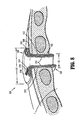
- FIG. 8 is a cross-sectional view illustrating another embodiment of the access assembly positioned between within the intercostal space.
- proximal should be understood as referring to the end of the access assembly, or component thereof, that is closer to the clinician during proper use, while the term “distal” should be understood as referring to the end that is farther from the clinician, as is traditional and conventional in the art.
- tissue herein below should be understood to encompass both the patient's ribs, and any surrounding tissues.
- FIGS. 1-4 illustrate one embodiment of the presently disclosed surgical access assembly, which is identified by the reference character 100, in use during the course of a minimally invasive thoracic surgical procedure.
- the access assembly 100 is depicted as a thoracic port that is configured and dimensioned for insertion into the intercostal space located between the adjacent ribs "R" of a patient in order to allow for the insertion and manipulation of one or more surgical instruments within the thoracic cavity "T" ( FIGS. 1, 3 ).
- the access assembly 100 may be formed from any suitable biocompatible material of a strength suitable for the purpose described herein, including, but not limited to, polymeric materials.
- the access assembly 100 is configured and dimensioned to extend into the thoracic cavity "T" ( FIGS. 1, 3 ) through the intercostal space, and includes a hollow body portion 102 ( FIG. 2 ) that extends along a longitudinal axis "Y."
- the body portion 102 includes a proximal portion 104 with an open proximal end 106, a distal portion 108 with an open distal end 110, and defines an internal space 112 that is configured and dimensioned to receive one or more surgical instruments "I" ( FIG. 4 ).
- the proximal portion 104 of the body portion 102 includes a transverse dimension "T1" that is larger than a transverse dimension "T2" defined by the distal portion 108.
- the larger transverse dimension "T1" of the proximal portion 104 facilitates manual engagement, e.g., gripping, by the clinician, and defines a flange, or buffer, 114 that is configured and dimensioned for abutment with the patient's tissue, e.g., the patient's ribs "R" ( FIGS. 1, 3 ) during distal advancement of the access assembly 100 through the intercostal space.
- Contact between the flange 114 and the patient's tissue prevents the access assembly 100 from passing entirely into the thoracic cavity "T" ( FIGS. 1, 3 ).
- the distal portion 108 of the body portion 102 includes a cross-sectional configuration defining a first transverse dimension "X1" that extends along a first transverse axis "X,” and a second, smaller transverse dimension “Z1” that extends along a second transverse axis “Z,” as best seen in FIG. 2 .
- the disparity between the transverse dimensions "X1," “Z1" of the distal portion 108 allows the access assembly 100 to better conform to the configuration and dimensions of the intercostal space, while maximizing available space within the body portion 102 to facilitate the insertion and manipulation of the surgical instrument(s) "I” ( FIG. 4 ), and minimizing the application of force "F” in the direction indicated in FIG. 3 , e.g., to spread the patient's ribs "R.”
- force "F” patient trauma is substantially reduced, as well as patient discomfort during recovery, and the overall recovery period.
- the distal portion 108 of the body portion 102 includes a pair of first sidewalls 116 ( FIG. 2 ), and pair of second sidewalls 118.
- the pair of first sidewalls 116 are illustrated as arcuate in configuration
- the pair of second sidewalls 118 are illustrated as substantially planar in configuration, whereby the distal portion 108 includes an elongated substantially, oval cross-sectional configuration.
- the substantially planar configuration of the pair of second sidewalls 118 maximizes the surface area available for contact with the patient's tissue.
- both the pair of first sidewalls 116 and the pair of second sidewalls 118 may be substantially planar in configuration such that the cross-sectional configuration of the body portion 102 is substantially rectangular.
- both pairs of sidewalls 116, 118 may include arcuate profiles in order to further facilitate spreading of the patient's ribs, as well as maximization of the internal space 112 ( FIGS. 2, 3 ) defined within the body portion 102.
- the access assembly 100 will be discussed during the course of a minimally invasive thoracic procedure. Initially, an opening is made in the patient's outer tissue wall of the thoracic body cavity by conventional means, such as by puncture via an obturator (not shown). Thereafter, the access assembly 100 is inserted through the opening into in the intercostal space between adjacent ribs, as shown in FIGS. 1 and 3 . The access assembly 100 is advanced distally until the flange 114 defined by the proximal portion 104 is positioned in abutment with the patient's tissue, e.g., the patient's ribs "R,” as shown in FIG. 4 .
- the body portion 102 may be dimensioned such that the patient's ribs "R" ( FIGS. 1, 3 ) are spread apart, as indicated in FIG. 3 , during distal advancement of the access assembly 100. If necessary, in order to further spread the patient's ribs "R,” the access assembly 100 may be rotated, such as, for example, 90°. In order to maintain displacement of the patient's ribs "R” in the manner described, and/or the maintenance of suitable available space within the body portion 102 of the access assembly 100 to facilitate the insertion and manipulation of the surgical instrument(s) "I" ( FIG. 4 ), it is envisioned that the material comprising the access assembly 100 may be of sufficient rigidity to resist excessive bending under the conditions normally encountered during such a surgical procedure.
- the surgical instrument “I” may be any surgical instrument that is configured and dimensioned to pass through the body portion 102 of the access assembly 100, and adapted to perform a surgical, diagnostic, or other desired procedure.
- suitable surgical instruments “I” may include endoscopic apparatus, which perform a variety of functions such as the application of surgical clips or other such fasteners to, and/or the cutting of, body tissue.
- the instrument "I” can be withdrawn from the access assembly 100, and the access assembly 100 can be removed from the intercostal space.
- FIGS. 5-8 alternative embodiments of the presently disclosed access assembly will be discussed.
- Each embodiment disclosed hereinbelow is substantially similar to the access assembly 100 discussed above with respect to FIGS. 1-4 , and accordingly, will only be discussed with respect to any difference therefrom.
- FIG. 5 illustrates an embodiment of the presently disclosed access assembly that is identified by the reference character 200.
- the access assembly 200 includes a body portion 202 having a proximal portion 204, a distal portion 206, and an intermediate portion 208 extending therebetween along a longitudinal axis "Y.”
- the proximal portion 204 includes respective first and second pairs of sidewalls 210, 212 that extend in substantially parallel relation such that the proximal portion 204 defines a substantially rectangular configuration.
- proximal portion 204 includes alternative configurations for the proximal portion 204, such as oval, are not beyond the scope of the present disclosure.
- the configuration and dimensions of the proximal portion 204 facilitates the insertion into, and the removal of the surgical instrument(s) "I" ( FIG. 4 ) from, the access assembly 200.
- the intermediate portion 208 extends distally from the proximal portion 204 and can be integral (monolithic) with the distal portion 206 and/or the proximal portion 204 or alternatively can be a separate element connected to the distal portion 206 and/or the proximal portion 204.
- the intermediate portion 208 includes respective first and second pairs of sidewalls 214, 216 corresponding to the sidewalls 210, 212 of the proximal portion 204.
- the first pair of sidewalls 214 taper in a distal direction inwardly towards the longitudinal axis "Y.”
- the inward taper of the first pair of sidewalls 214 guides the surgical instrument(s) "I” upon insertion into the access assembly 200 to facilitate passage into the thoracic cavity "T", and provides a surface that is configured and dimensioned for abutment with the patient's tissue to prevent the surgical access assembly 200 from passing entirely into the internal work site, e.g. the thoracic cavity.
- the tapered configuration of the first pair of sidewalls 214 provides increased internal space for manipulation of surgical instrument(s), e.g. instrument "I" of FIG.
- the proximal portion has a larger transverse dimension to facilitate manipulation and to define a flange or buffer to prevent the access assembly from passing entirely into the thoracic cavity.
- the respective first and second pairs of sidewalls 214, 216 of the intermediate portion 208 are each illustrated as substantially planar in configuration. In alternative embodiments of the present disclosure, however, it is envisioned that the either or both of the respective first and second pairs of sidewalls 214, 216 may include an arcuate profile.
- the distal portion 206 extends distally from the intermediate portion 208, and includes a wall 218 of a substantially cylindrical configuration defining an opening that extends therethrough. It should be appreciated, however, that the distal portion 206 may include other geometrical configurations, e.g., rectangular, in alternative embodiments of the present disclosure.
- the opening in wall 218 is configured and dimensioned to facilitate passage of surgical instrument(s), e.g. instrument "I" of FIG.4 , through the patient's tissue and into the internal work site.
- FIG. 6 illustrates another embodiment of the presently disclosed access assembly, which is identified by the reference character 300.
- the access assembly 300 incorporates substantially compliant structure, either partially or wholly. The incorporation of compliant structure allows for reconfiguration of the access assembly 300 during insertion, removal, and manipulation of the surgical instrument(s), e.g. instrument "I" of FIG. 4 .
- the ability of the access assembly 300 to be reconfigured during use maximizes the space available within the access assembly 300 for manipulation of the surgical instrument(s) positioned therethrough, and facilitates if desired more precise conformity with the shape of the intercostal space, thereby restricting movement of the access assembly 300 during the course of the surgical procedure, and consequently, any effect upon the patient's tissue that might otherwise result from such movement.
- incorporating compliant structure into the access assembly 300 allows for a reduction in the forces applied to the patient's tissue during the course of the surgical procedure, if any, e.g., during insertion, removal, and/or manipulation of the surgical instrument(s), thereby reducing the influence of such forces upon the patient's tissues, and consequently, patient trauma, discomfort following the procedure, and recovery time.
- the access assembly 300 includes a body portion 302 that is formed from the aforementioned compliant material, e.g., PU foam.
- a compliant material e.g., PU foam.
- the incorporation of such a material allows the body portion 302 of the access assembly 300 to better conform to the shape of the intercostal space defined between the patient's adjacent ribs "R.”
- the compliant material minimizes the force "F" ( FIG. 3 ) applied to the patient's tissue during insertion and removal of the access assembly 300, which thereby minimizes any undesirable impact upon the patient's tissue.
- the compliant material acts to dissipate any load transmitted to the intercostal nerve to further reduce patient trauma, discomfort following the procedure, and recovery time.
- the proximal portion has a larger transverse dimension to facilitate manipulation and to define a flange or buffer to prevent the access assembly from passing entirely into the thoracic cavity.
- the body portion 302 While illustrated as including a body portion 302 with a substantially rectangular in cross-sectional configuration, in alternative embodiments of the access assembly 300, it is envisioned that the body portion 302 may assume other geometrical configurations, e.g., oval. Also, the entire body portion 302 can be formed from compliant material, or alternatively, only portions thereof.
- FIG. 7 illustrates another embodiment of the presently disclosed access assembly, which is identified by the reference character 400.
- the access assembly 400 includes a body portion 402 that extends along a longitudinal axis "Y" with an inner liner 404 and an outer liner 406 that is positioned thereabout.
- the outer liner 406 may be overmolded to the body portion 402, or that that inner liner 404 and the outer liner 406 may be connected through the use of an adhesive or other methods.
- the outer liner 406 is formed from a substantially compliant material, e.g., a material having a lower durometer than the material comprising the inner liner 404, either partially or wholly.
- the outer liner can be formed from a biocompatible gel. Consequently, during use of the access assembly 400, the compliant outer liner 406 provides a cushioned contact area between the body portion 402 and the patient's tissue, e.g., the patient's ribs "R" ( FIGS. 1, 3 ). Specifically, the patient's ribs "R,” and the surrounding tissues, deform the outer liner 406 inwardly towards the longitudinal axis "Y.”
- the access assembly 400 is illustrated as including respective first and second pairs of first sidewalls 408, 410 that are substantially planar in configuration, whereby the body portion 402 includes a substantially rectangular cross-sectional configuration, alternative geometrical configurations for the access assembly 400 are not beyond the scope of the present disclosure.
- at least one of the respective first and second pairs of sidewalls 408, 410 may have an arcuate profile such that the cross-sectional configuration of the body portion 402 is substantially oval.
- the access assembly 500 includes a body portion 502 having a proximal portion 504 and a distal portion 506.
- the proximal portion 504 defines a transverse dimension "X1" that is larger than the transverse dimension "X2" defined by the distal portion 506, whereby the proximal portion 504 defines a flange, or buffer, 508.
- the flange 508 is configured and dimensioned for engagement with the patient's tissue upon positioning of the access assembly 500 within the intercostal space, as shown in FIG.
- the access assembly 500 may further include a distal flange (not shown) defining a transverse dimension larger than the transverse dimension "X2" defined by the distal portion 506 to facilitate engagement with a distal surface of the patient's tissue, e.g., in order to further enhance stability of the access assembly 500.
- the body portion 502 includes an inner membrane 510 and an outer membrane 512 which collectively define a cavity 514.
- the respective inner and outer membranes 510, 512 may be formed from any suitable biocompatible material that is capable of retaining a fluid, e.g., air, water, or saline, within the cavity 514, i.e., a substantially impermeable material.
- the cavity 514 is filled with the aforementioned fluid in order to transition the access assembly 500 between a deflated condition (not shown) and an inflated condition ( FIG. 8 ).
- the fluid may be introduced into the inner cavity 514 in any suitable manner, e.g., via a port 516 included on the outer membrane 512 that is in fluid communication with the inner cavity 514 via a lumen 518.
- Inflating the access assembly 500 provides a measure of resiliency and deformability that cushions the patient's tissue during the course of the surgical procedure, and evenly distributes any applied forces, e.g., during insertion, removal, and/or manipulation of the surgical instrument(s), e.g. instrument "I” of FIG. 4 . Additionally, the inflatability of the access assembly 500 allows the access assembly 500 to more precisely conform to the shape of the intercostal space. Conformity with the specific configuration and dimensions of the intercostal space minimizes the force "F" ( FIG. 3 ) necessary to securely position the access assembly 500, and the need to separate the patient's ribs "R," which in turn, reduces patient trauma, as well as patient discomfort during recovery, and the overall recovery period.
- the access assembly 500 is illustrated as including a substantially circular cross-sectional configuration, alternative geometrical configurations for the access assembly 500 are not beyond the scope of the present disclosure.
- the access assembly 500 may include substantially planar and/or arcuate sidewalls such that the cross-sectional configuration of the access assembly 500 is substantially rectangular.
- the access assemblies described herein can be used in other surgical procedures, including, but not limited to the replacement or reparation of a diseased or damaged valve, such as the repair and replacement of mitral, aortic, and other heart valves, repair of atrial and ventricular septal defects, pulmonary thrombectomy, treatment of aneurysms, electrophysiological mapping and ablation of the myocardium, and any other procedure in which interventional devices are introduced into the interior of the heart or a great vessel, as well as annuloplasty, quadrangular resection, commissurotomy, shortening mitral or tricuspid valve chordae tendonae, reattachment of severed mitral or tricuspid valve chordae tendonae or papillary muscle tissue, decalcification of valve and annulus tissue, and the like.
- minimally invasive as used herein also includes such procedures.
Landscapes
- Health & Medical Sciences (AREA)
- Surgery (AREA)
- Life Sciences & Earth Sciences (AREA)
- Biomedical Technology (AREA)
- Nuclear Medicine, Radiotherapy & Molecular Imaging (AREA)
- Engineering & Computer Science (AREA)
- Pathology (AREA)
- Heart & Thoracic Surgery (AREA)
- Medical Informatics (AREA)
- Molecular Biology (AREA)
- Animal Behavior & Ethology (AREA)
- General Health & Medical Sciences (AREA)
- Public Health (AREA)
- Veterinary Medicine (AREA)
- Surgical Instruments (AREA)
Abstract
Description
- This application claims the benefit of
U.S. Provisional Patent Application No. 61/107,749, filed on October 23, 2008 - The present disclosure relates generally to devices and techniques for performing minimally invasive surgical procedures. More particularly, the present disclosure relates to a device that is configured and dimensioned for positioning within an intercostal space to facilitate access to an internal surgical work site with one or more surgical instruments.
- In an effort to reduce trauma and recovery time, many surgical procedures are performed through small openings in the skin, such as an incision or a natural body orifice. For example, these procedures include laparoscopic procedures and thoracic procedures, such as those that are performed to investigate, diagnose, and treat diseases. Throughout the present disclosure, the term "minimally invasive" should be understood to encompass any and all such procedures.
- Specific surgical instruments have been developed for use during minimally invasive surgical procedures, and typically include a shaft with an end effector, or operating portion, that is positioned at a distal end thereof. Dependent upon the requirements of the particular procedure, the end effector may include, for example, graspers, clip appliers, staplers, and the like.
- During the minimally invasive procedure, the clinician often creates an opening through the patient's body wall using an obturator or trocar, and thereafter, positions an access assembly, such as a cannula assembly, within the opening. The access assembly typically includes an elongate access sleeve that is configured and dimensioned to receive one or more of the above-mentioned surgical instruments such that the end effector can be positioned within an internal work site adjacent the tissue that is the subject of the procedure.
- Unlike laparoscopic surgery, which requires insufflation of the abdominal cavity to provide an operative region for the clinician, thoracic surgery does not require the introduction of insufflation gas into the thoracic cavity. Thus, the design of access assemblies intended for use during thoracic surgery can be simplified since the presence of a seal, or valve, is not essential.
- In minimally invasive thoracic surgeries, the access assembly is generally inserted into a space located between adjacent ribs that is known as the intercostal space. After penetration of the patient's body wall is accomplished, the obturator can be removed from the access assembly, and one or more surgical instruments can be inserted into the internal work site therethrough.
- In the interests of facilitating visualization, the introduction of certain surgical instruments, and/or the removal of tissue specimens during minimally invasive thoracic procedures, it may be desirable to spread the adjacent ribs defining the intercostal space. Additionally, during these procedures, firm, reliable placement of the access assembly is also desirable in order to allow the access assembly to withstand forces that are applied during manipulation of the instrument(s) inserted therethrough. However, reducing patient trauma during the procedure, discomfort during recovery, and the overall recovery time remain issues of importance.
- In one aspect of the present disclosure, a surgical access assembly is disclosed that is configured and dimensioned for positioning within an opening in tissue which provides access to an intercostal space defined between a patient's adjacent ribs in order to facilitate the passage of a surgical instrument into an internal work site. The body portion has an inner liner formed from a first material and defining an internal space that is configured and dimensioned to removably receive the surgical instrument, and an outer liner that is positioned about the inner liner. The outer liner is formed from a second material having a lower durometer than the first material such that the outer liner is resiliently deformable to facilitate conformity with the intercostal space to minimize the application of force to the patient's tissue upon insertion and removal of the access assembly and manipulation of the surgical instrument within the internal space.
- In one embodiment of the disclosed access assembly, the body portion may include a substantially rectangular cross-sectional configuration. The body portion may include sidewalls that are substantially planar and/or arcuate in configuration.
- The surgical access assembly may include a body portion with a proximal portion that defines a first transverse dimension, and a distal portion that defines a second, smaller transverse dimension. The configuration and dimensions of the proximal portion facilitate engagement with the patient's tissue to prevent passage of the access assembly entirely into the internal work site.
- In another aspect of the present disclosure, a surgical access assembly is disclosed that is configured and dimensioned to facilitate access to an internal work site through an intercostal space defined between a patient's adjacent ribs. The surgical access assembly includes a body portion having a proximal portion and a distal portion, and defines an internal space that is configured and dimensioned to receive a surgical instrument. The body portion incorporates an inner membrane and an outer membrane defining a cavity. The inner membrane and the outer membrane are formed from a biocompatible material that is substantially impermeable such that the cavity is capable of retaining a fluid therein.
- The surgical access assembly is repositionable between deflated and inflated conditions upon communication of the fluid to and from the cavity such that the access assembly is resiliently deformable to thereby facilitate conformity with the intercostal space in order to minimize the application of force to the patient's tissue upon insertion and removal of the access assembly and manipulation of the surgical instrument within the internal space.
- The access assembly may include proximal and distal portions, wherein the proximal portion is configured and dimensioned to prevent the access assembly from passing entirely into the internal work site, e.g., the proximal portion may define a first transverse dimension, whereas the distal portion may define a second, smaller transverse dimension.
- As with the surgical access assembly discussed in connection with the aforedescribed aspect of the present disclosure, in one embodiment, it is envisioned that the body portion may include a substantially rectangular cross-sectional configuration. The body portion may include sidewalls that are substantially planar and/or arcuate in configuration.
- In another aspect of the present disclosure, a method of facilitating access to an internal work site beneath a patient's tissue is disclosed. The method includes the steps of (i) forming an opening in the patient's tissue; (ii) advancing an access assembly through the opening in a deflated condition such that the access assembly is positioned within an intercostal space defined between the patient's adjacent ribs; (iii) inflating the access assembly via communication of a fluid into a cavity defined between inner and outer membranes of the access assembly, whereby the access assembly conforms to the intercostal space to facilitate secured positioning thereof; (iv) inserting the surgical instrument into the internal work site through the access assembly; and (v) performing a surgical procedure utilizing the surgical instrument.
- The step of inflating the access assembly may include causing a proximal portion thereof to define a first transverse dimension greater than a second transverse dimension defined by a distal portion thereof such that the proximal portion is configured and dimensioned for engagement with the patient's tissue to prevent passage of the access assembly entirely into the internal work site.
- Upon inflation, the body portion of the surgical access assembly may be caused to realize a substantially rectangular cross-sectional configuration to facilitate conformity with the intercostal space. The body portion may be caused to define substantially planar sidewalls to maximize available surface area for contact with the patient's tissue, and/or at least one pair of arcuate sidewalls.
- In still another aspect of the present disclosure, a method of facilitating access to an internal work site beneath a patient's tissue is disclosed. The method includes the steps of (i) forming an opening in the patient's tissue; (ii) advancing an access assembly through the opening into an intercostal space defined between the patient's adjacent ribs such that an outer liner of the access assembly is resiliently deformed to facilitate conformity with the intercostal space; (iii) inserting a surgical instrument into the internal work site through the access assembly; and (iv) performing a surgical procedure utilizing the surgical instrument.
- Preferably, the step of inflating the access assembly includes causing a proximal portion thereof to define a first transverse dimension greater than a second transverse dimension defined by a distal portion thereof such that the proximal portion is configured and dimensioned for engagement with the patient's tissue to prevent passage of the access assembly entirely into the internal work site.
- Preferably, the step of inflating the surgical access assembly may include causing a distal portion thereof to realize a substantially rectangular cross-sectional configuration to facilitate conformity with the intercostal space.
- Preferably, the step of inflating the surgical access assembly may include causing the distal portion thereof to define substantially planar sidewalls to maximize available surface area for contact with the patient's tissue.
- Preferably still, the step of inflating a surgical access assembly includes causing the distal portion thereof to define at least one pair of arcuate sidewalls.
- According to a further aspect of the invention, there is provided a method of facilitating access to an internal work site beneath a patient's tissue comprising the steps of:
- forming an opening in the patient's tissue;
- advancing an access assembly through the opening into an intercostal space defined between the patient's adjacent ribs such that an outer liner of the access assembly is resiliently deformed to facilitate conformity with the intercostal space;
- inserting a surgical instrument into the internal work site through the access assembly; and
- performing a surgical procedure utilizing the surgical instrument.
- The surgical access assembly may include a body portion with an inner liner positioned in contact with the outer liner, wherein the inner liner is formed from a first material, and the outer liner is formed from a second material having a lower durometer than the first material. Upon positioning within the opening, the inner liner may establish a passageway to the internal work site that extends longitudinally therethrough. It is envisioned that the proximal portion of the access assembly may be caused to abut the patient's tissue to prevent passage of the access assembly entirely into the internal work site.
- Various exemplary embodiments of the present disclosure are described herein below with reference to the drawings, wherein:
-
FIG. 1 is a front view illustrating a patient's skeletal structure with one embodiment of the presently disclosed surgical access assembly positioned between the intercostal space defined between the patient's adjacent ribs in accordance with the present disclosure; -
FIG. 2 is a top, perspective view of the access assembly ofFIG. 1 ; -
FIG. 3 is a side, perspective view of the access assembly ofFIG. 1 positioned within the intercostal space; -
FIG. 4 is a side, perspective view of the access assembly ofFIG. 1 positioned within the intercostal space with a surgical instrument inserted therethrough; -
FIG. 5 is a front, perspective view of an alternative embodiment of the access assembly of the present disclosure; -
FIG. 6 is a side, perspective view illustrating another embodiment of the access assembly positioned within the intercostal space; -
FIG. 7 is a side, perspective view of an yet another embodiment of the access assembly; and -
FIG. 8 is a cross-sectional view illustrating another embodiment of the access assembly positioned between within the intercostal space. - Various embodiments of the presently disclosed access assembly, and methods of using the same, will now be described in detail with reference to the drawings wherein like references numerals identify similar or identical elements. In the drawings, and in the following description, the term "proximal" should be understood as referring to the end of the access assembly, or component thereof, that is closer to the clinician during proper use, while the term "distal" should be understood as referring to the end that is farther from the clinician, as is traditional and conventional in the art. Additionally, use of the term "tissue" herein below should be understood to encompass both the patient's ribs, and any surrounding tissues.
-
FIGS. 1-4 illustrate one embodiment of the presently disclosed surgical access assembly, which is identified by thereference character 100, in use during the course of a minimally invasive thoracic surgical procedure. As such, in the embodiment of theaccess assembly 100 seen inFIGS. 1-4 , theaccess assembly 100 is depicted as a thoracic port that is configured and dimensioned for insertion into the intercostal space located between the adjacent ribs "R" of a patient in order to allow for the insertion and manipulation of one or more surgical instruments within the thoracic cavity "T" (FIGS. 1, 3 ). It is envisioned that theaccess assembly 100 may be formed from any suitable biocompatible material of a strength suitable for the purpose described herein, including, but not limited to, polymeric materials. - The
access assembly 100 is configured and dimensioned to extend into the thoracic cavity "T" (FIGS. 1, 3 ) through the intercostal space, and includes a hollow body portion 102 (FIG. 2 ) that extends along a longitudinal axis "Y." Thebody portion 102 includes aproximal portion 104 with an openproximal end 106, adistal portion 108 with an opendistal end 110, and defines aninternal space 112 that is configured and dimensioned to receive one or more surgical instruments "I" (FIG. 4 ). - As best seen in
FIG. 2 , in one embodiment of theaccess assembly 100, theproximal portion 104 of thebody portion 102 includes a transverse dimension "T1" that is larger than a transverse dimension "T2" defined by thedistal portion 108. The larger transverse dimension "T1" of theproximal portion 104 facilitates manual engagement, e.g., gripping, by the clinician, and defines a flange, or buffer, 114 that is configured and dimensioned for abutment with the patient's tissue, e.g., the patient's ribs "R" (FIGS. 1, 3 ) during distal advancement of theaccess assembly 100 through the intercostal space. Contact between theflange 114 and the patient's tissue prevents theaccess assembly 100 from passing entirely into the thoracic cavity "T" (FIGS. 1, 3 ). - In one embodiment of the
access assembly 100, thedistal portion 108 of thebody portion 102 includes a cross-sectional configuration defining a first transverse dimension "X1" that extends along a first transverse axis "X," and a second, smaller transverse dimension "Z1" that extends along a second transverse axis "Z," as best seen inFIG. 2 . The disparity between the transverse dimensions "X1," "Z1" of thedistal portion 108 allows theaccess assembly 100 to better conform to the configuration and dimensions of the intercostal space, while maximizing available space within thebody portion 102 to facilitate the insertion and manipulation of the surgical instrument(s) "I" (FIG. 4 ), and minimizing the application of force "F" in the direction indicated inFIG. 3 , e.g., to spread the patient's ribs "R." By minimizing the force "F," patient trauma is substantially reduced, as well as patient discomfort during recovery, and the overall recovery period. - The
distal portion 108 of thebody portion 102 includes a pair of first sidewalls 116 (FIG. 2 ), and pair ofsecond sidewalls 118. In the embodiment of theaccess assembly 100 illustrated inFIGS. 1-4 , the pair offirst sidewalls 116 are illustrated as arcuate in configuration, whereas the pair ofsecond sidewalls 118 are illustrated as substantially planar in configuration, whereby thedistal portion 108 includes an elongated substantially, oval cross-sectional configuration. The substantially planar configuration of the pair ofsecond sidewalls 118 maximizes the surface area available for contact with the patient's tissue. - In an alternative embodiment of the
access assembly 100, it is envisioned that both the pair offirst sidewalls 116 and the pair ofsecond sidewalls 118 may be substantially planar in configuration such that the cross-sectional configuration of thebody portion 102 is substantially rectangular. - The specific configuration and dimensions of the
access assembly 100 ma y be varied in alternative embodiments of the present disclosure based on such factors as the anatomy of the patient to be treated, and the surgical instruments to be used in conjunction therewith. As such, it is further envisioned that both pairs ofsidewalls FIGS. 2, 3 ) defined within thebody portion 102. - With continued reference to
FIGS. 1-4 , use and operation of theaccess assembly 100 will be discussed during the course of a minimally invasive thoracic procedure. Initially, an opening is made in the patient's outer tissue wall of the thoracic body cavity by conventional means, such as by puncture via an obturator (not shown). Thereafter, theaccess assembly 100 is inserted through the opening into in the intercostal space between adjacent ribs, as shown inFIGS. 1 and3 . Theaccess assembly 100 is advanced distally until theflange 114 defined by theproximal portion 104 is positioned in abutment with the patient's tissue, e.g., the patient's ribs "R," as shown inFIG. 4 . - As mentioned above, it is envisioned that the body portion 102 (
FIG. 2 ) may be dimensioned such that the patient's ribs "R" (FIGS. 1, 3 ) are spread apart, as indicated inFIG. 3 , during distal advancement of theaccess assembly 100. If necessary, in order to further spread the patient's ribs "R," theaccess assembly 100 may be rotated, such as, for example, 90°. In order to maintain displacement of the patient's ribs "R" in the manner described, and/or the maintenance of suitable available space within thebody portion 102 of theaccess assembly 100 to facilitate the insertion and manipulation of the surgical instrument(s) "I" (FIG. 4 ), it is envisioned that the material comprising theaccess assembly 100 may be of sufficient rigidity to resist excessive bending under the conditions normally encountered during such a surgical procedure. - Referring now to
FIG. 4 in particular, theaccess assembly 100 is shown inserted into the thoracic cavity "T" (FIGS. 1, 3 ) between adjacent ribs "R" with a surgical instrument "I" inserted therethrough. The surgical instrument "I" may be any surgical instrument that is configured and dimensioned to pass through thebody portion 102 of theaccess assembly 100, and adapted to perform a surgical, diagnostic, or other desired procedure. For example, suitable surgical instruments "I" may include endoscopic apparatus, which perform a variety of functions such as the application of surgical clips or other such fasteners to, and/or the cutting of, body tissue. - Following completed use of the surgical instrument "I," the instrument "I" can be withdrawn from the
access assembly 100, and theaccess assembly 100 can be removed from the intercostal space. - With reference now to
FIGS. 5-8 , alternative embodiments of the presently disclosed access assembly will be discussed. Each embodiment disclosed hereinbelow is substantially similar to theaccess assembly 100 discussed above with respect toFIGS. 1-4 , and accordingly, will only be discussed with respect to any difference therefrom. -
FIG. 5 illustrates an embodiment of the presently disclosed access assembly that is identified by thereference character 200. Theaccess assembly 200 includes abody portion 202 having aproximal portion 204, adistal portion 206, and anintermediate portion 208 extending therebetween along a longitudinal axis "Y." - The
proximal portion 204 includes respective first and second pairs ofsidewalls proximal portion 204 defines a substantially rectangular configuration. However, it should be appreciated that alternative configurations for theproximal portion 204, such as oval, are not beyond the scope of the present disclosure. The configuration and dimensions of theproximal portion 204 facilitates the insertion into, and the removal of the surgical instrument(s) "I" (FIG. 4 ) from, theaccess assembly 200. - The
intermediate portion 208 extends distally from theproximal portion 204 and can be integral (monolithic) with thedistal portion 206 and/or theproximal portion 204 or alternatively can be a separate element connected to thedistal portion 206 and/or theproximal portion 204. Theintermediate portion 208 includes respective first and second pairs ofsidewalls sidewalls proximal portion 204. The first pair ofsidewalls 214 taper in a distal direction inwardly towards the longitudinal axis "Y." The inward taper of the first pair ofsidewalls 214 guides the surgical instrument(s) "I" upon insertion into theaccess assembly 200 to facilitate passage into the thoracic cavity "T", and provides a surface that is configured and dimensioned for abutment with the patient's tissue to prevent thesurgical access assembly 200 from passing entirely into the internal work site, e.g. the thoracic cavity. Additionally, the tapered configuration of the first pair ofsidewalls 214 provides increased internal space for manipulation of surgical instrument(s), e.g. instrument "I" ofFIG. 4 , and acts to distribute the load applied to the patient during insertion and manipulation of the surgical instrument(s) in order to reduce patient trauma during the procedure. The proximal portion has a larger transverse dimension to facilitate manipulation and to define a flange or buffer to prevent the access assembly from passing entirely into the thoracic cavity. - In the embodiment of the
access assembly 200 illustrated inFIG. 5 , the respective first and second pairs ofsidewalls intermediate portion 208 are each illustrated as substantially planar in configuration. In alternative embodiments of the present disclosure, however, it is envisioned that the either or both of the respective first and second pairs ofsidewalls - The
distal portion 206 extends distally from theintermediate portion 208, and includes awall 218 of a substantially cylindrical configuration defining an opening that extends therethrough. It should be appreciated, however, that thedistal portion 206 may include other geometrical configurations, e.g., rectangular, in alternative embodiments of the present disclosure. The opening inwall 218 is configured and dimensioned to facilitate passage of surgical instrument(s), e.g. instrument "I" ofFIG.4 , through the patient's tissue and into the internal work site. -
FIG. 6 illustrates another embodiment of the presently disclosed access assembly, which is identified by thereference character 300. In contrast to the aforedescribed embodiments, which are formed primarily from a substantially rigid material, theaccess assembly 300, and each variation thereof discussed hereinbelow, incorporates substantially compliant structure, either partially or wholly. The incorporation of compliant structure allows for reconfiguration of theaccess assembly 300 during insertion, removal, and manipulation of the surgical instrument(s), e.g. instrument "I" ofFIG. 4 . The ability of theaccess assembly 300 to be reconfigured during use maximizes the space available within theaccess assembly 300 for manipulation of the surgical instrument(s) positioned therethrough, and facilitates if desired more precise conformity with the shape of the intercostal space, thereby restricting movement of theaccess assembly 300 during the course of the surgical procedure, and consequently, any effect upon the patient's tissue that might otherwise result from such movement. Moreover, incorporating compliant structure into theaccess assembly 300 allows for a reduction in the forces applied to the patient's tissue during the course of the surgical procedure, if any, e.g., during insertion, removal, and/or manipulation of the surgical instrument(s), thereby reducing the influence of such forces upon the patient's tissues, and consequently, patient trauma, discomfort following the procedure, and recovery time. - The
access assembly 300 includes abody portion 302 that is formed from the aforementioned compliant material, e.g., PU foam. The incorporation of such a material allows thebody portion 302 of theaccess assembly 300 to better conform to the shape of the intercostal space defined between the patient's adjacent ribs "R." Additionally, the compliant material minimizes the force "F" (FIG. 3 ) applied to the patient's tissue during insertion and removal of theaccess assembly 300, which thereby minimizes any undesirable impact upon the patient's tissue. For example, the compliant material acts to dissipate any load transmitted to the intercostal nerve to further reduce patient trauma, discomfort following the procedure, and recovery time. The proximal portion has a larger transverse dimension to facilitate manipulation and to define a flange or buffer to prevent the access assembly from passing entirely into the thoracic cavity. - While illustrated as including a
body portion 302 with a substantially rectangular in cross-sectional configuration, in alternative embodiments of theaccess assembly 300, it is envisioned that thebody portion 302 may assume other geometrical configurations, e.g., oval. Also, theentire body portion 302 can be formed from compliant material, or alternatively, only portions thereof. -
FIG. 7 illustrates another embodiment of the presently disclosed access assembly, which is identified by thereference character 400. Theaccess assembly 400 includes abody portion 402 that extends along a longitudinal axis "Y" with aninner liner 404 and anouter liner 406 that is positioned thereabout. For example, it is envisioned that theouter liner 406 may be overmolded to thebody portion 402, or that thatinner liner 404 and theouter liner 406 may be connected through the use of an adhesive or other methods. - Whereas the
inner liner 404 is formed from a substantially rigid material, theouter liner 406 is formed from a substantially compliant material, e.g., a material having a lower durometer than the material comprising theinner liner 404, either partially or wholly. By way of example, the outer liner can be formed from a biocompatible gel. Consequently, during use of theaccess assembly 400, the compliantouter liner 406 provides a cushioned contact area between thebody portion 402 and the patient's tissue, e.g., the patient's ribs "R" (FIGS. 1, 3 ). Specifically, the patient's ribs "R," and the surrounding tissues, deform theouter liner 406 inwardly towards the longitudinal axis "Y." - Although the
access assembly 400 is illustrated as including respective first and second pairs offirst sidewalls body portion 402 includes a substantially rectangular cross-sectional configuration, alternative geometrical configurations for theaccess assembly 400 are not beyond the scope of the present disclosure. For example, it is envisioned that at least one of the respective first and second pairs ofsidewalls body portion 402 is substantially oval. - With reference now to
FIG. 8 , another embodiment of the presently disclosed access assembly, which is identified by thereference character 500, will be discussed. Theaccess assembly 500 includes abody portion 502 having aproximal portion 504 and adistal portion 506. Theproximal portion 504 defines a transverse dimension "X1" that is larger than the transverse dimension "X2" defined by thedistal portion 506, whereby theproximal portion 504 defines a flange, or buffer, 508. Theflange 508 is configured and dimensioned for engagement with the patient's tissue upon positioning of theaccess assembly 500 within the intercostal space, as shown inFIG. 8 , in order to prevent theaccess assembly 500 from passing entirely into the thoracic cavity "T." In one embodiment, it is envisioned that theaccess assembly 500 may further include a distal flange (not shown) defining a transverse dimension larger than the transverse dimension "X2" defined by thedistal portion 506 to facilitate engagement with a distal surface of the patient's tissue, e.g., in order to further enhance stability of theaccess assembly 500. - The
body portion 502 includes aninner membrane 510 and anouter membrane 512 which collectively define acavity 514. The respective inner andouter membranes cavity 514, i.e., a substantially impermeable material. During use of theaccess assembly 500, thecavity 514 is filled with the aforementioned fluid in order to transition theaccess assembly 500 between a deflated condition (not shown) and an inflated condition (FIG. 8 ). It is envisioned that the fluid may be introduced into theinner cavity 514 in any suitable manner, e.g., via aport 516 included on theouter membrane 512 that is in fluid communication with theinner cavity 514 via alumen 518. - Inflating the
access assembly 500 provides a measure of resiliency and deformability that cushions the patient's tissue during the course of the surgical procedure, and evenly distributes any applied forces, e.g., during insertion, removal, and/or manipulation of the surgical instrument(s), e.g. instrument "I" ofFIG. 4 . Additionally, the inflatability of theaccess assembly 500 allows theaccess assembly 500 to more precisely conform to the shape of the intercostal space. Conformity with the specific configuration and dimensions of the intercostal space minimizes the force "F" (FIG. 3 ) necessary to securely position theaccess assembly 500, and the need to separate the patient's ribs "R," which in turn, reduces patient trauma, as well as patient discomfort during recovery, and the overall recovery period. - Although the
access assembly 500 is illustrated as including a substantially circular cross-sectional configuration, alternative geometrical configurations for theaccess assembly 500 are not beyond the scope of the present disclosure. For example, it is envisioned that theaccess assembly 500 may include substantially planar and/or arcuate sidewalls such that the cross-sectional configuration of theaccess assembly 500 is substantially rectangular. - Although described for use in thoracic procedures, it should also be understood that the access assemblies described herein can be used in other surgical procedures, including, but not limited to the replacement or reparation of a diseased or damaged valve, such as the repair and replacement of mitral, aortic, and other heart valves, repair of atrial and ventricular septal defects, pulmonary thrombectomy, treatment of aneurysms, electrophysiological mapping and ablation of the myocardium, and any other procedure in which interventional devices are introduced into the interior of the heart or a great vessel, as well as annuloplasty, quadrangular resection, commissurotomy, shortening mitral or tricuspid valve chordae tendonae, reattachment of severed mitral or tricuspid valve chordae tendonae or papillary muscle tissue, decalcification of valve and annulus tissue, and the like. The term "minimally invasive" as used herein also includes such procedures.
- Persons skilled in the art will understand that the devices and methods specifically described herein and illustrated in the accompanying figures are non-limiting exemplary embodiments, and that the description, disclosure, and figures should be construed merely exemplary of particular embodiments. It is to be understood, therefore, that the present disclosure is not limited to the precise embodiments described, and that various other changes and modifications may be effected by one skilled in the art without departing from the scope or spirit of the disclosure. Additionally, it is envisioned that the elements and features illustrated or described in connection with one exemplary embodiment may be combined with the elements and features of another without departing from the scope of the present disclosure, and that such modifications and variations are also intended to be included within the scope of the present disclosure. Accordingly, the subject matter of the present disclosure is not to be limited by what has been particularly shown and described, except as indicated by the appended claims.
Claims (12)
- A surgical access assembly configured and dimensioned for positioning within an opening in tissue providing access to an intercostal space defined between a patient's adjacent ribs to facilitate passage of a surgical instrument into an internal work site, the surgical access assembly comprising a body portion having an inner liner defining an internal space that is configured and dimensioned to removably receive the surgical instrument, and an outer liner positioned about the inner liner, the inner liner being formed from a first material, and the outer liner being formed from a second material having a lower durometer than the first material such that the outer liner is resiliently deformable to thereby facilitate conformity with the intercostal space to minimize the application of force to the patient's tissue upon insertion and removal of the access assembly and manipulation of the surgical instrument within the internal space.
- The surgical access assembly of claim 1, wherein the outer liner is formed from a biocompatible gel.
- The surgical access assembly of claim 1 or claim 2, wherein the outer liner is overmolded to the inner liner.
- The surgical access assembly of any preceding claim wherein the body portion of the access assembly includes a substantially rectangular cross-sectional configuration.
- The surgical access assembly of any one of the preceding claims, wherein the body portion of the access assembly includes substantially planar sidewalls.
- The surgical access assembly of claim 4 or claim 5, wherein the body portion of the access assembly includes at least one pair of arcuate sidewalls.
- The surgical access assembly of any one of the preceding claims, wherein the body portion includes a proximal portion defining a first transverse dimension, and a distal portion defining a second, smaller transverse dimension, the proximal portion being configured and dimensioned for engagement with the patient's tissue to prevent passage of the access assembly entirely into the internal work site.
- A surgical access assembly configured and dimensioned to facilitate access to an internal work site through an intercostal space defined between a patient's adjacent ribs, the surgical access assembly comprising a body portion having a proximal portion and a distal portion, the body portion defining an internal space configured and dimensioned to receive a surgical instrument, and including an inner membrane and an outer membrane defining a cavity therebetween configured and dimensioned to retain a fluid therein, the inner membrane and the outer membrane being formed from a substantially impermeable biocompatible material, wherein the surgical access assembly is repositionable between deflated and inflated conditions upon communication of the fluid to and from the cavity to facilitate resilient deformation of the access assembly and conformity with the intercostal space to minimize the application of force to the patient's tissue upon insertion and removal of the access assembly and manipulation of the surgical instrument within the internal space.
- The surgical access assembly of claim 8, wherein the distal portion includes a substantially rectangular cross-sectional configuration.
- The surgical access assembly of claim 8 or claim 9, wherein the distal portion includes substantially planar sidewalls.
- The surgical access assembly of claim 9 or claim 10, wherein the distal portion includes at least one pair of arcuate sidewalls.
- The surgical access assembly of any one of the preceding claims, wherein the proximal portion defines a first transverse dimension, and the distal portion defines a second, smaller transverse dimension such that the proximal portion is configured and dimensioned for engagement with the patient's tissue to prevent passage of the access assembly entirely through the intercostal space.
Applications Claiming Priority (2)
| Application Number | Priority Date | Filing Date | Title |
|---|---|---|---|
| US10774908P | 2008-10-23 | 2008-10-23 | |
| US12/576,295 US20100168522A1 (en) | 2008-10-23 | 2009-10-09 | Surgical access assembly |
Publications (2)
| Publication Number | Publication Date |
|---|---|
| EP2179699A1 true EP2179699A1 (en) | 2010-04-28 |
| EP2179699B1 EP2179699B1 (en) | 2016-01-06 |
Family
ID=41600723
Family Applications (1)
| Application Number | Title | Priority Date | Filing Date |
|---|---|---|---|
| EP09252473.5A Not-in-force EP2179699B1 (en) | 2008-10-23 | 2009-10-23 | Surgical access assembly |
Country Status (5)
| Country | Link |
|---|---|
| US (1) | US20100168522A1 (en) |
| EP (1) | EP2179699B1 (en) |
| JP (1) | JP2010099475A (en) |
| AU (1) | AU2009227871A1 (en) |
| CA (1) | CA2683250A1 (en) |
Cited By (13)
| Publication number | Priority date | Publication date | Assignee | Title |
|---|---|---|---|---|
| EP2417922A1 (en) * | 2010-08-12 | 2012-02-15 | Tyco Healthcare Group LP | Expandable thoracic access port |
| EP2417921A1 (en) * | 2010-08-12 | 2012-02-15 | Tyco Healthcare Group LP | Thoracic access port |
| US20120143007A1 (en) * | 2010-12-01 | 2012-06-07 | Fiona Middlemiss Haig | Thoracic port with changing elasticity |
| US8540628B2 (en) | 2010-02-12 | 2013-09-24 | Covidien Lp | Expandable thoracic access port |
| US8864658B2 (en) | 2010-08-12 | 2014-10-21 | Covidien Lp | Expandable surgical access port |
| US8888691B2 (en) | 2011-01-24 | 2014-11-18 | Covidien Lp | Expanding surgical access port |
| US8961408B2 (en) | 2010-08-12 | 2015-02-24 | Covidien Lp | Expandable surgical access port |
| US8961409B2 (en) | 2011-12-07 | 2015-02-24 | Covidien Lp | Thoracic access assembly |
| US9039610B2 (en) | 2011-05-19 | 2015-05-26 | Covidien Lp | Thoracic access port |
| US9119665B2 (en) | 2011-03-21 | 2015-09-01 | Covidien Lp | Thoracic access port including foldable anchor |
| US10987128B2 (en) | 2017-03-22 | 2021-04-27 | Covidien Lp | Cannula assembly |
| US11141191B2 (en) | 2020-01-15 | 2021-10-12 | Covidien Lp | Surgical access assembly |
| US12251130B2 (en) | 2021-05-03 | 2025-03-18 | Covidien Lp | Surgical access device having a balloon and methods for manufacturing the same |
Families Citing this family (13)
| Publication number | Priority date | Publication date | Assignee | Title |
|---|---|---|---|---|
| EP2259733B1 (en) * | 2008-03-06 | 2014-07-23 | Cook Medical Technologies LLC | Medical systems for accessing an internal bodily opening |
| AU2009246137B2 (en) * | 2008-05-15 | 2013-10-10 | Cook Medical Technologies Llc | Systems, devices and methods for accessing a bodily opening |
| WO2010088509A1 (en) * | 2009-01-30 | 2010-08-05 | Wilson-Cook Medical, Inc. | Expandable port for accessing a bodily opening |
| US20100228095A1 (en) * | 2009-03-06 | 2010-09-09 | Lanx, Inc. | Surgical retractor |
| US20110196208A1 (en) * | 2009-03-06 | 2011-08-11 | Lanx, Inc. | Asymetrical surgical retractor |
| US8834361B2 (en) * | 2009-05-15 | 2014-09-16 | Cook Medical Technologies Llc | Systems, devices and methods for accessing a bodily opening |
| AU2010300450B2 (en) * | 2009-10-02 | 2013-10-31 | Cook Medical Technologies Llc | Apparatus for single port access |
| US20110082370A1 (en) * | 2009-10-02 | 2011-04-07 | Wilson-Cook Medical Inc. | Endoscopic fascia tunneling |
| US9339264B2 (en) | 2010-10-01 | 2016-05-17 | Cook Medical Technologies Llc | Port access visualization platform |
| US8777849B2 (en) | 2010-02-12 | 2014-07-15 | Covidien Lp | Expandable thoracic access port |
| JP6302467B2 (en) * | 2013-05-31 | 2018-03-28 | 利昭 森川 | Thoracoscopic trocar and thoracoscopic port instrumentation kit |
| DE102019110982B4 (en) * | 2019-04-29 | 2021-02-18 | Corlife Ohg | Intracorporeal guide component |
| JP2024038659A (en) * | 2022-09-08 | 2024-03-21 | 株式会社八光 | thoracoscopic surgical port |
Citations (5)
| Publication number | Priority date | Publication date | Assignee | Title |
|---|---|---|---|---|
| US6312377B1 (en) * | 2000-04-06 | 2001-11-06 | Viamedics, Llc | Soft tissue compression shield and method of retracting tissue |
| US6451054B1 (en) | 1993-02-22 | 2002-09-17 | Hearport, Inc. | Less-invasive devices and methods for treatment of cardiac valves |
| US20050013760A1 (en) | 2003-04-23 | 2005-01-20 | Kenji Ito | High-pressure phase silicon nitride having a cubic spinel structure and the manufacturing method |
| US20050137460A1 (en) * | 2003-11-12 | 2005-06-23 | Bertolero Arthur A. | Retractor with inflatable blades |
| US20070060884A1 (en) * | 2005-09-13 | 2007-03-15 | The Cleveland Clinic Foundation | Apparatus for insertion between a medical tube and a body tissue opening |
Family Cites Families (14)
| Publication number | Priority date | Publication date | Assignee | Title |
|---|---|---|---|---|
| US3777330A (en) * | 1972-09-08 | 1973-12-11 | Huffel I Van | Maintenance means for tape player cabinets |
| US4011624A (en) * | 1975-08-25 | 1977-03-15 | The Black And Decker Manufacturing Company | Cordless vacuum cleaner |
| GR930100244A (en) * | 1992-06-30 | 1994-02-28 | Ethicon Inc | Flexible endoscopic surgical port |
| US5613937A (en) * | 1993-02-22 | 1997-03-25 | Heartport, Inc. | Method of retracting heart tissue in closed-chest heart surgery using endo-scopic retraction |
| US5588949A (en) * | 1993-10-08 | 1996-12-31 | Heartport, Inc. | Stereoscopic percutaneous visualization system |
| WO1999026270A1 (en) * | 1997-11-14 | 1999-05-27 | Tdk Corporation | Core for deflecting yoke and deflecting yoke |
| JP2000268717A (en) * | 1999-03-19 | 2000-09-29 | Hitachi Ltd | Cathode ray tube and method of manufacturing the same |
| US6340038B1 (en) * | 2001-04-18 | 2002-01-22 | Hopkins Manufacturing Corporation | Versatile pouring system including a funnel and spouts |
| US6974048B2 (en) * | 2002-08-28 | 2005-12-13 | James Edwin Funk | Safety tool for containing debris from electrical work |
| KR100507035B1 (en) * | 2002-10-07 | 2005-08-09 | 엘지전자 주식회사 | Subsidiary suction tool for vacuum cleaner |
| US20050022336A1 (en) * | 2003-07-31 | 2005-02-03 | Overvaag Chad D. | Cleaning tool assembly |
| US7811251B2 (en) * | 2005-10-13 | 2010-10-12 | Tyco Healthcare Group Lp | Trocar anchor |
| US7214199B1 (en) * | 2006-03-29 | 2007-05-08 | B. Well Veterinary Products, Inc. | Urine analysis collection kit for veterinary use |
| US20090126649A1 (en) * | 2007-11-19 | 2009-05-21 | Furminator, Inc. | Pet Grooming Tool with Vacuum or Blower Attachment and Method of Using the Same |
-
2009
- 2009-10-09 US US12/576,295 patent/US20100168522A1/en not_active Abandoned
- 2009-10-19 CA CA2683250A patent/CA2683250A1/en not_active Abandoned
- 2009-10-20 AU AU2009227871A patent/AU2009227871A1/en not_active Abandoned
- 2009-10-21 JP JP2009242687A patent/JP2010099475A/en active Pending
- 2009-10-23 EP EP09252473.5A patent/EP2179699B1/en not_active Not-in-force
Patent Citations (5)
| Publication number | Priority date | Publication date | Assignee | Title |
|---|---|---|---|---|
| US6451054B1 (en) | 1993-02-22 | 2002-09-17 | Hearport, Inc. | Less-invasive devices and methods for treatment of cardiac valves |
| US6312377B1 (en) * | 2000-04-06 | 2001-11-06 | Viamedics, Llc | Soft tissue compression shield and method of retracting tissue |
| US20050013760A1 (en) | 2003-04-23 | 2005-01-20 | Kenji Ito | High-pressure phase silicon nitride having a cubic spinel structure and the manufacturing method |
| US20050137460A1 (en) * | 2003-11-12 | 2005-06-23 | Bertolero Arthur A. | Retractor with inflatable blades |
| US20070060884A1 (en) * | 2005-09-13 | 2007-03-15 | The Cleveland Clinic Foundation | Apparatus for insertion between a medical tube and a body tissue opening |
Cited By (25)
| Publication number | Priority date | Publication date | Assignee | Title |
|---|---|---|---|---|
| US8540628B2 (en) | 2010-02-12 | 2013-09-24 | Covidien Lp | Expandable thoracic access port |
| US9597114B2 (en) | 2010-08-12 | 2017-03-21 | Covidien Lp | Expandable surgical access port |
| US9168031B2 (en) | 2010-08-12 | 2015-10-27 | Covidien Lp | Expandable thoracic access port |
| EP2417922A1 (en) * | 2010-08-12 | 2012-02-15 | Tyco Healthcare Group LP | Expandable thoracic access port |
| EP2535010A1 (en) * | 2010-08-12 | 2012-12-19 | Tyco Healthcare Group LP | Thoracic access port |
| EP2417921A1 (en) * | 2010-08-12 | 2012-02-15 | Tyco Healthcare Group LP | Thoracic access port |
| US8597180B2 (en) | 2010-08-12 | 2013-12-03 | Covidien Lp | Expandable thoracic access port |
| CN102397105B (en) * | 2010-08-12 | 2016-02-10 | 柯惠Lp公司 | Expandable thoracic access port |
| US9247955B2 (en) | 2010-08-12 | 2016-02-02 | Covidien Lp | Thoracic access port |
| US8961408B2 (en) | 2010-08-12 | 2015-02-24 | Covidien Lp | Expandable surgical access port |
| US8864658B2 (en) | 2010-08-12 | 2014-10-21 | Covidien Lp | Expandable surgical access port |
| CN102397105A (en) * | 2010-08-12 | 2012-04-04 | Tyco医疗健康集团 | Expandable thoracic access port |
| US20120143007A1 (en) * | 2010-12-01 | 2012-06-07 | Fiona Middlemiss Haig | Thoracic port with changing elasticity |
| US8888691B2 (en) | 2011-01-24 | 2014-11-18 | Covidien Lp | Expanding surgical access port |
| US9308021B2 (en) | 2011-01-24 | 2016-04-12 | Covidien Lp | Expanding surgical access port |
| US9549722B2 (en) | 2011-03-21 | 2017-01-24 | Covidien Lp | Thoracic access port including foldable anchor |
| US9119665B2 (en) | 2011-03-21 | 2015-09-01 | Covidien Lp | Thoracic access port including foldable anchor |
| US9039610B2 (en) | 2011-05-19 | 2015-05-26 | Covidien Lp | Thoracic access port |
| US10420541B2 (en) | 2011-05-19 | 2019-09-24 | Covidien Lp | Thoracic access port |
| US9629657B2 (en) | 2011-12-07 | 2017-04-25 | Covidien Lp | Thoracic access assembly |
| US8961409B2 (en) | 2011-12-07 | 2015-02-24 | Covidien Lp | Thoracic access assembly |
| US11864792B2 (en) | 2017-03-22 | 2024-01-09 | Covidien Lp | Cannula assembly |
| US10987128B2 (en) | 2017-03-22 | 2021-04-27 | Covidien Lp | Cannula assembly |
| US11141191B2 (en) | 2020-01-15 | 2021-10-12 | Covidien Lp | Surgical access assembly |
| US12251130B2 (en) | 2021-05-03 | 2025-03-18 | Covidien Lp | Surgical access device having a balloon and methods for manufacturing the same |
Also Published As
| Publication number | Publication date |
|---|---|
| CA2683250A1 (en) | 2010-04-23 |
| EP2179699B1 (en) | 2016-01-06 |
| JP2010099475A (en) | 2010-05-06 |
| AU2009227871A1 (en) | 2010-05-13 |
| US20100168522A1 (en) | 2010-07-01 |
Similar Documents
| Publication | Publication Date | Title |
|---|---|---|
| EP2179699B1 (en) | Surgical access assembly | |
| JP5653157B2 (en) | Free height foam port | |
| JP5683231B2 (en) | Foam introduction system with modified port shape | |
| US8398667B2 (en) | Surgical device having indicia for cutting to size | |
| EP2374423A1 (en) | Universal height access port | |
| US9028403B2 (en) | Access port having rollable proximal end | |
| US20110251465A1 (en) | Hollow multi-lumen access port | |
| EP2392275A2 (en) | Pressure feedback access ports for minimally invasive surgery | |
| US9113952B1 (en) | Surgical access assembly and method of use therefor | |
| US8574155B2 (en) | Expandable surgical access port | |
| KR20100112087A (en) | Retractor with flexible sleeve | |
| WO2007140449A2 (en) | Bifurcated endoscopy cannula | |
| EP2535010B1 (en) | Thoracic access port | |
| EP3909531B1 (en) | Surgical access device with air release mechanism | |
| US20210275215A1 (en) | Surgical access assembly having a pump | |
| AU2019284089A1 (en) | Access assembly including flexible cannula | |
| JP5503451B2 (en) | Surgical device having indicia for cutting to an appropriate size | |
| US20210299416A1 (en) | Balloon cannula including a plurality of balloons | |
| US20210259730A1 (en) | Surgical access assembly having a button inflator | |
| EP2308400A1 (en) | Foam collar for surgical access devices |
Legal Events
| Date | Code | Title | Description |
|---|---|---|---|
| PUAI | Public reference made under article 153(3) epc to a published international application that has entered the european phase |
Free format text: ORIGINAL CODE: 0009012 |
|
| AK | Designated contracting states |
Kind code of ref document: A1 Designated state(s): AT BE BG CH CY CZ DE DK EE ES FI FR GB GR HR HU IE IS IT LI LT LU LV MC MK MT NL NO PL PT RO SE SI SK SM TR |
|
| AX | Request for extension of the european patent |
Extension state: AL BA RS |
|
| 17P | Request for examination filed |
Effective date: 20101025 |
|
| RAP1 | Party data changed (applicant data changed or rights of an application transferred) |
Owner name: COVIDIEN LP |
|
| GRAP | Despatch of communication of intention to grant a patent |
Free format text: ORIGINAL CODE: EPIDOSNIGR1 |
|
| INTG | Intention to grant announced |
Effective date: 20150709 |
|
| GRAS | Grant fee paid |
Free format text: ORIGINAL CODE: EPIDOSNIGR3 |
|
| GRAA | (expected) grant |
Free format text: ORIGINAL CODE: 0009210 |
|
| AK | Designated contracting states |
Kind code of ref document: B1 Designated state(s): AT BE BG CH CY CZ DE DK EE ES FI FR GB GR HR HU IE IS IT LI LT LU LV MC MK MT NL NO PL PT RO SE SI SK SM TR |
|
| REG | Reference to a national code |
Ref country code: GB Ref legal event code: FG4D |
|
| REG | Reference to a national code |
Ref country code: CH Ref legal event code: EP |
|
| REG | Reference to a national code |
Ref country code: IE Ref legal event code: FG4D |
|
| REG | Reference to a national code |
Ref country code: AT Ref legal event code: REF Ref document number: 768152 Country of ref document: AT Kind code of ref document: T Effective date: 20160215 |
|
| REG | Reference to a national code |
Ref country code: DE Ref legal event code: R096 Ref document number: 602009035530 Country of ref document: DE |
|
| REG | Reference to a national code |
Ref country code: LT Ref legal event code: MG4D |
|
| REG | Reference to a national code |
Ref country code: NL Ref legal event code: MP Effective date: 20160106 |
|
| REG | Reference to a national code |
Ref country code: AT Ref legal event code: MK05 Ref document number: 768152 Country of ref document: AT Kind code of ref document: T Effective date: 20160106 |
|
| PG25 | Lapsed in a contracting state [announced via postgrant information from national office to epo] |
Ref country code: NL Free format text: LAPSE BECAUSE OF FAILURE TO SUBMIT A TRANSLATION OF THE DESCRIPTION OR TO PAY THE FEE WITHIN THE PRESCRIBED TIME-LIMIT Effective date: 20160106 |
|
| PG25 | Lapsed in a contracting state [announced via postgrant information from national office to epo] |
Ref country code: GR Free format text: LAPSE BECAUSE OF FAILURE TO SUBMIT A TRANSLATION OF THE DESCRIPTION OR TO PAY THE FEE WITHIN THE PRESCRIBED TIME-LIMIT Effective date: 20160407 Ref country code: HR Free format text: LAPSE BECAUSE OF FAILURE TO SUBMIT A TRANSLATION OF THE DESCRIPTION OR TO PAY THE FEE WITHIN THE PRESCRIBED TIME-LIMIT Effective date: 20160106 Ref country code: NO Free format text: LAPSE BECAUSE OF FAILURE TO SUBMIT A TRANSLATION OF THE DESCRIPTION OR TO PAY THE FEE WITHIN THE PRESCRIBED TIME-LIMIT Effective date: 20160406 Ref country code: FI Free format text: LAPSE BECAUSE OF FAILURE TO SUBMIT A TRANSLATION OF THE DESCRIPTION OR TO PAY THE FEE WITHIN THE PRESCRIBED TIME-LIMIT Effective date: 20160106 Ref country code: IT Free format text: LAPSE BECAUSE OF FAILURE TO SUBMIT A TRANSLATION OF THE DESCRIPTION OR TO PAY THE FEE WITHIN THE PRESCRIBED TIME-LIMIT Effective date: 20160106 Ref country code: ES Free format text: LAPSE BECAUSE OF FAILURE TO SUBMIT A TRANSLATION OF THE DESCRIPTION OR TO PAY THE FEE WITHIN THE PRESCRIBED TIME-LIMIT Effective date: 20160106 |
|
| PG25 | Lapsed in a contracting state [announced via postgrant information from national office to epo] |
Ref country code: PL Free format text: LAPSE BECAUSE OF FAILURE TO SUBMIT A TRANSLATION OF THE DESCRIPTION OR TO PAY THE FEE WITHIN THE PRESCRIBED TIME-LIMIT Effective date: 20160106 Ref country code: PT Free format text: LAPSE BECAUSE OF FAILURE TO SUBMIT A TRANSLATION OF THE DESCRIPTION OR TO PAY THE FEE WITHIN THE PRESCRIBED TIME-LIMIT Effective date: 20160506 Ref country code: AT Free format text: LAPSE BECAUSE OF FAILURE TO SUBMIT A TRANSLATION OF THE DESCRIPTION OR TO PAY THE FEE WITHIN THE PRESCRIBED TIME-LIMIT Effective date: 20160106 Ref country code: SE Free format text: LAPSE BECAUSE OF FAILURE TO SUBMIT A TRANSLATION OF THE DESCRIPTION OR TO PAY THE FEE WITHIN THE PRESCRIBED TIME-LIMIT Effective date: 20160106 Ref country code: LV Free format text: LAPSE BECAUSE OF FAILURE TO SUBMIT A TRANSLATION OF THE DESCRIPTION OR TO PAY THE FEE WITHIN THE PRESCRIBED TIME-LIMIT Effective date: 20160106 Ref country code: LT Free format text: LAPSE BECAUSE OF FAILURE TO SUBMIT A TRANSLATION OF THE DESCRIPTION OR TO PAY THE FEE WITHIN THE PRESCRIBED TIME-LIMIT Effective date: 20160106 Ref country code: IS Free format text: LAPSE BECAUSE OF FAILURE TO SUBMIT A TRANSLATION OF THE DESCRIPTION OR TO PAY THE FEE WITHIN THE PRESCRIBED TIME-LIMIT Effective date: 20160506 |
|
| REG | Reference to a national code |
Ref country code: FR Ref legal event code: PLFP Year of fee payment: 8 |
|
| REG | Reference to a national code |
Ref country code: DE Ref legal event code: R097 Ref document number: 602009035530 Country of ref document: DE |
|
| PG25 | Lapsed in a contracting state [announced via postgrant information from national office to epo] |
Ref country code: EE Free format text: LAPSE BECAUSE OF FAILURE TO SUBMIT A TRANSLATION OF THE DESCRIPTION OR TO PAY THE FEE WITHIN THE PRESCRIBED TIME-LIMIT Effective date: 20160106 Ref country code: DK Free format text: LAPSE BECAUSE OF FAILURE TO SUBMIT A TRANSLATION OF THE DESCRIPTION OR TO PAY THE FEE WITHIN THE PRESCRIBED TIME-LIMIT Effective date: 20160106 |
|
| PGFP | Annual fee paid to national office [announced via postgrant information from national office to epo] |
Ref country code: GB Payment date: 20160928 Year of fee payment: 8 Ref country code: IE Payment date: 20160922 Year of fee payment: 8 |
|
| PLBE | No opposition filed within time limit |
Free format text: ORIGINAL CODE: 0009261 |
|
| STAA | Information on the status of an ep patent application or granted ep patent |
Free format text: STATUS: NO OPPOSITION FILED WITHIN TIME LIMIT |
|
| PG25 | Lapsed in a contracting state [announced via postgrant information from national office to epo] |
Ref country code: SM Free format text: LAPSE BECAUSE OF FAILURE TO SUBMIT A TRANSLATION OF THE DESCRIPTION OR TO PAY THE FEE WITHIN THE PRESCRIBED TIME-LIMIT Effective date: 20160106 Ref country code: CZ Free format text: LAPSE BECAUSE OF FAILURE TO SUBMIT A TRANSLATION OF THE DESCRIPTION OR TO PAY THE FEE WITHIN THE PRESCRIBED TIME-LIMIT Effective date: 20160106 Ref country code: SK Free format text: LAPSE BECAUSE OF FAILURE TO SUBMIT A TRANSLATION OF THE DESCRIPTION OR TO PAY THE FEE WITHIN THE PRESCRIBED TIME-LIMIT Effective date: 20160106 Ref country code: RO Free format text: LAPSE BECAUSE OF FAILURE TO SUBMIT A TRANSLATION OF THE DESCRIPTION OR TO PAY THE FEE WITHIN THE PRESCRIBED TIME-LIMIT Effective date: 20160106 |
|
| PGFP | Annual fee paid to national office [announced via postgrant information from national office to epo] |
Ref country code: FR Payment date: 20160921 Year of fee payment: 8 |
|
| 26N | No opposition filed |
Effective date: 20161007 |
|
| PG25 | Lapsed in a contracting state [announced via postgrant information from national office to epo] |
Ref country code: BE Free format text: LAPSE BECAUSE OF FAILURE TO SUBMIT A TRANSLATION OF THE DESCRIPTION OR TO PAY THE FEE WITHIN THE PRESCRIBED TIME-LIMIT Effective date: 20160106 |
|
| PGFP | Annual fee paid to national office [announced via postgrant information from national office to epo] |
Ref country code: DE Payment date: 20160922 Year of fee payment: 8 |
|
| PG25 | Lapsed in a contracting state [announced via postgrant information from national office to epo] |
Ref country code: BG Free format text: LAPSE BECAUSE OF FAILURE TO SUBMIT A TRANSLATION OF THE DESCRIPTION OR TO PAY THE FEE WITHIN THE PRESCRIBED TIME-LIMIT Effective date: 20160406 Ref country code: SI Free format text: LAPSE BECAUSE OF FAILURE TO SUBMIT A TRANSLATION OF THE DESCRIPTION OR TO PAY THE FEE WITHIN THE PRESCRIBED TIME-LIMIT Effective date: 20160106 |
|
| REG | Reference to a national code |
Ref country code: CH Ref legal event code: PL |
|
| PG25 | Lapsed in a contracting state [announced via postgrant information from national office to epo] |
Ref country code: LI Free format text: LAPSE BECAUSE OF NON-PAYMENT OF DUE FEES Effective date: 20161031 Ref country code: CH Free format text: LAPSE BECAUSE OF NON-PAYMENT OF DUE FEES Effective date: 20161031 |
|
| PG25 | Lapsed in a contracting state [announced via postgrant information from national office to epo] |
Ref country code: LU Free format text: LAPSE BECAUSE OF NON-PAYMENT OF DUE FEES Effective date: 20161023 |
|
| REG | Reference to a national code |
Ref country code: DE Ref legal event code: R119 Ref document number: 602009035530 Country of ref document: DE |
|
| PG25 | Lapsed in a contracting state [announced via postgrant information from national office to epo] |
Ref country code: HU Free format text: LAPSE BECAUSE OF FAILURE TO SUBMIT A TRANSLATION OF THE DESCRIPTION OR TO PAY THE FEE WITHIN THE PRESCRIBED TIME-LIMIT; INVALID AB INITIO Effective date: 20091023 Ref country code: CY Free format text: LAPSE BECAUSE OF FAILURE TO SUBMIT A TRANSLATION OF THE DESCRIPTION OR TO PAY THE FEE WITHIN THE PRESCRIBED TIME-LIMIT Effective date: 20160106 |
|
| GBPC | Gb: european patent ceased through non-payment of renewal fee |
Effective date: 20171023 |
|
| PG25 | Lapsed in a contracting state [announced via postgrant information from national office to epo] |
Ref country code: MC Free format text: LAPSE BECAUSE OF FAILURE TO SUBMIT A TRANSLATION OF THE DESCRIPTION OR TO PAY THE FEE WITHIN THE PRESCRIBED TIME-LIMIT Effective date: 20160106 Ref country code: MT Free format text: LAPSE BECAUSE OF NON-PAYMENT OF DUE FEES Effective date: 20161031 Ref country code: TR Free format text: LAPSE BECAUSE OF FAILURE TO SUBMIT A TRANSLATION OF THE DESCRIPTION OR TO PAY THE FEE WITHIN THE PRESCRIBED TIME-LIMIT Effective date: 20160106 Ref country code: MK Free format text: LAPSE BECAUSE OF FAILURE TO SUBMIT A TRANSLATION OF THE DESCRIPTION OR TO PAY THE FEE WITHIN THE PRESCRIBED TIME-LIMIT Effective date: 20160106 |
|
| REG | Reference to a national code |
Ref country code: IE Ref legal event code: MM4A |
|
| REG | Reference to a national code |
Ref country code: FR Ref legal event code: ST Effective date: 20180629 |
|
| PG25 | Lapsed in a contracting state [announced via postgrant information from national office to epo] |
Ref country code: DE Free format text: LAPSE BECAUSE OF NON-PAYMENT OF DUE FEES Effective date: 20180501 Ref country code: GB Free format text: LAPSE BECAUSE OF NON-PAYMENT OF DUE FEES Effective date: 20171023 |
|
| PG25 | Lapsed in a contracting state [announced via postgrant information from national office to epo] |
Ref country code: FR Free format text: LAPSE BECAUSE OF NON-PAYMENT OF DUE FEES Effective date: 20171031 |
|
| PG25 | Lapsed in a contracting state [announced via postgrant information from national office to epo] |
Ref country code: IE Free format text: LAPSE BECAUSE OF NON-PAYMENT OF DUE FEES Effective date: 20171023 |