EP2178169A1 - Three-fold polarization diversity antenna - Google Patents
Three-fold polarization diversity antenna Download PDFInfo
- Publication number
- EP2178169A1 EP2178169A1 EP08166982A EP08166982A EP2178169A1 EP 2178169 A1 EP2178169 A1 EP 2178169A1 EP 08166982 A EP08166982 A EP 08166982A EP 08166982 A EP08166982 A EP 08166982A EP 2178169 A1 EP2178169 A1 EP 2178169A1
- Authority
- EP
- European Patent Office
- Prior art keywords
- slot
- polarization diversity
- diversity antenna
- antenna
- conductive layer
- Prior art date
- Legal status (The legal status is an assumption and is not a legal conclusion. Google has not performed a legal analysis and makes no representation as to the accuracy of the status listed.)
- Granted
Links
Images


Classifications
-
- H—ELECTRICITY
- H01—ELECTRIC ELEMENTS
- H01Q—ANTENNAS, i.e. RADIO AERIALS
- H01Q13/00—Waveguide horns or mouths; Slot antennas; Leaky-waveguide antennas; Equivalent structures causing radiation along the transmission path of a guided wave
- H01Q13/10—Resonant slot antennas
- H01Q13/18—Resonant slot antennas the slot being backed by, or formed in boundary wall of, a resonant cavity ; Open cavity antennas
-
- H—ELECTRICITY
- H01—ELECTRIC ELEMENTS
- H01Q—ANTENNAS, i.e. RADIO AERIALS
- H01Q9/00—Electrically-short antennas having dimensions not more than twice the operating wavelength and consisting of conductive active radiating elements
- H01Q9/04—Resonant antennas
- H01Q9/0407—Substantially flat resonant element parallel to ground plane, e.g. patch antenna
- H01Q9/045—Substantially flat resonant element parallel to ground plane, e.g. patch antenna with particular feeding means
-
- H—ELECTRICITY
- H01—ELECTRIC ELEMENTS
- H01Q—ANTENNAS, i.e. RADIO AERIALS
- H01Q9/00—Electrically-short antennas having dimensions not more than twice the operating wavelength and consisting of conductive active radiating elements
- H01Q9/04—Resonant antennas
- H01Q9/30—Resonant antennas with feed to end of elongated active element, e.g. unipole
Definitions
- This patent application relates to an antenna apparatus.
- this patent application relates to an antenna having polarization diversity.
- the electric field of a propagating electromagnetic wave has two linear components that are orthogonal to one another. Typically, these components trace out an ellipse as a function of time. However, the electromagnetic wave might have only a single electric field component, in which case the electromagnetic wave is said to be linearly polarized.
- a polarization diverse antenna can be used to improve signal transmission/reception quality in multipath environments since the signal strength received by such antennas can be greater than with a single linearly polarized antenna.
- a polarization diverse antenna can also be used to increase network capacity since multiple signals of the same frequency, but different polarizations, can be transmitted from and/or received at a single antenna.
- Zhang (US 6,593,891 ) describes a polarization diverse antenna that comprises a dielectric substrate having an upper conductive surface. A cross-shaped slot is formed in the upper conductive surface. The lower surface of the dielectric includes elongated conductive strips that are aligned with the arms of the slot, and a rectangular conductive portion that is aligned with the centre of the slot. The antenna also includes a pair of feed lines, each attached to a respective one of the conductive strips.
- a linear polarization diversity antenna may have a single feed/receive line, but have a complex structure to transmit/receive the orthogonal components of the electromagnetic wave.
- Thudor (US 7,336,233 ) describes a polarization diverse antenna that comprises five slots that are arranged in a H-shaped structure on the upper surface of a dielectric substrate. A single feed line is disposed on the lower surface of the dielectric substrate, and is perpendicular to the centre slot. The antenna also includes a switching means that are positioned in the middle of each slot, except the middle slot.
- Milyakh (US 7,358,916 ) describes a polarization diverse antenna that comprises four right-angled bent conductive strips that are disposed on a dielectric substrate. The antenna also includes a switching network comprising diodes that are formed between the ends of adjacent strips. A single feed line is connected between the diagonally opposite strips, at the bent portion thereof.
- a common problem of dual-polarized antenna is the high possibility of crosstalk between the polarized components.
- this patent application describes a three-fold polarization diversity antenna that comprises a slot-loaded patch, and a radiation member that is electromagnetically coupled to the slot-loaded patch.
- the radiation member extends through a plane of the slot-loaded patch.
- this patent application describes a wireless communications device that comprises a radio transceiver section, and a three-fold polarization diversity antenna that is coupled to the radio transceiver section.
- the three-fold diversity antenna comprises a slot-loaded patch, and a radiation member that is electromagnetically coupled to the slot-loaded patch. The radiation member extends through a plane of the slot-loaded patch.
- the radiation member may be disposed at a substantially right angle to the plane of the slot-loaded patch.
- the slot-loaded patch may comprise a pair of intersecting slots that extend through a planar conductive layer, with the intersecting slots being disposed at a substantially right angle to each other.
- the radiation member may terminate at one end within a central portion of the slot-loaded patch, such that the one end is physically isolated from the slot-loaded patch.
- the slot-loaded patch comprises a cross-slot-shaped through-hole that extends through the planar conductive layer.
- the radiation member comprises a monopole that extends between a feed point and a centre of the cross-slot-shaped through-hole.
- the monopole may comprise a ground plane, and an elongate conductor that extends from the ground plane and terminates in the centre of the cross-slot-shaped through-hole.
- the ground plane may be substantially parallel to the planar conductive layer, with the elongate conductor being disposed at a substantially right angle to the planar conductive layer and the ground plane.
- the three-fold polarization diversity antenna has a simple compact structure.
- the antenna also provides good isolation between the polarized components, and may be used in WLAN networks.
- a wireless communications device 100 that is configured to operate within a wireless network.
- the communications device 100 is a two-way wireless communications device.
- the wireless communications device 100 may be configured as a wireless base station, a portable wireless modem, or a wireless data communication device, as examples.
- the wireless communications device 100 includes a communication subsystem 102, and a data processing system 104 that is coupled to the communication subsystem 102.
- the communication subsystem 102 performs communication functions, and includes a wireless transmitter 106, a wireless receiver 108, and an internal antenna 200, a local oscillator (LOs) 110 and a digital signal processor (DSP) 112 connected to the transmitter 106 and the receiver 108.
- LOs local oscillator
- DSP digital signal processor
- the internal antenna 200 is a wide-band antenna that is configured for use with one or more of the application bands that are available within the wireless network. More preferably, the internal antenna 200 is configured for use within a WLAN (IEEE 802.11x) network.
- the internal antenna 200 will be discussed in detail below, with reference to Figs. 2 to 5 .
- the data processing system 104 comprises a microprocessor 114, a flash memory 116 and a data port 118.
- the flash memory 116 includes signal processing instructions for the DSP 112, and may also include computer processing instructions for the microprocessor 114.
- the computer processing instructions when accessed from the flash memory 116 and executed by the microprocessor 114 define an operating system that controls the overall operation of the communications device 100.
- the data processing system 104 may also include a volatile memory (RAM) 120.
- the computer processing instructions may be copied from the flash memory 116 into the RAM 120, and then accessed from the RAM 116 and executed by the microprocessor 114.
- the data port 118 interfaces the wireless communications device 100 with a communications network, such as a wired or wireless local area network (LAN) or wide area network (WAN).
- a communications network such as a wired or wireless local area network (LAN) or wide area network (WAN).
- Data packets that are received at the data processing system 104 from the communications network via the data port 118 are transferred by the operating system to the communication subsystem 102 for transmission as wireless electromagnetic signals over the wireless network.
- Wireless electromagnetic signals to be transmitted over the wireless network are processed by the DSP 112 and input to the transmitter 106 for digital to analog conversion, frequency up conversion, and transmission over the wireless network via the internal antenna 200.
- wireless electromagnetic signals that are received by the internal antenna 200 from the wireless network are input to the receiver 108, which performs common receiver functions such as frequency down conversion, and analog to digital (A/D) conversion, in preparation for more complex communication functions performed by the DSP 112.
- Data packets that are received at the data processing system 104 from the DSP 112 are transmitted by the operating system over the communications network via the data port 118.
- the communication subsystem 102 may include additional transmitters and/or receivers, depending upon the range of frequency bands over which communication is desired.
- the communication subsystem 102 is depicted in Fig. 1 with one antenna 200, it should be understood that the wireless communications device 100 may instead comprise two or more of the antennas 200.
- the communication subsystem 102 includes more than one DSP 112, the signals transmitted and received by the additional transmitter(s)/receiver(s) would preferably be processed by a different DSP than the transmitter 106 and the receiver 108.
- Figs. 2a and 2b depict the preferred structure of the three-fold polarization diversity antenna 200.
- the antenna 200 comprises a slot-loaded patch antenna structure 202, and a radiation member 204 that is electromagnetically coupled to the patch antenna structure 202.
- the patch antenna structure 202 comprises a conductive layer 206, and a slot-shaped aperture that extends through the conductive layer 206.
- the conductive layer 206 typically is substantially planar, and may have a substantially square planar shape. Alternately, the conductive layer 206 may have rectangular, elliptical or circular planar shape. Further, the conductive layer 206 need not be planar, but may have an arcuate shape.
- the slot-shaped aperture may comprise a pair of elongate linear intersecting slots 208a, 208b that extend through the conductive layer 206, between the upper and lower surfaces thereof, thereby forming a cross-slot-shaped through-hole in the conductive layer 206.
- the intersecting slots 208a, 208b are disposed at a substantially right angle to each other.
- the patch antenna structure 202 may comprise a single slot; or may comprise three linear intersecting slots oriented 120° with respect to each other.
- the radiation member 204 extends through a plane of the slot-loaded patch.
- the radiation member 204 is disposed at a substantially right angle to the plane of the slot-loaded patch.
- the radiation member 204 is configured as a grounded monopole, and comprises a planar ground plane 210, and an elongate conductor 212.
- the elongate conductor 212 is physically isolated from the ground plane 210, and extends from the ground plane 210, terminating proximate the centre portion of the slot-shaped aperture, between the upper and lower surfaces of the conductive layer 206. With this configuration, the field distributions produced by the antenna will be symmetric.
- the elongate conductor 212 may terminate at a position that is off-centre.
- the elongate conductor 212 extends vertically upwards through the ground plane 210 towards the slot-shaped aperture, from a feed point 214 that is disposed below the ground plane 210.
- the antenna 200 may include a dielectric substrate (not shown) that is disposed between the conductive layer 206 and the ground plane 210.
- the conductive layer 206 and the ground plane 210 are disposed on opposite faces of the dielectric substrate.
- the dielectric substrate is configured with a through-hole through which the elongate conductor 212 extends between the ground plane 210 and the conductive layer 206.
- the ground plane 210 may be oriented substantially parallel to the planar conductive layer 206.
- the elongate conductor 212 is disposed at a substantially right angle to the planar conductive layer 206 and the ground plane 210.
- the planar conductive layer 206 may be inclined relative to the ground plane 210 at an angle other than a right angle.
- terminal end may be disposed within the region 216 of the intersection of the intersecting slots 208a, 208b, between the upper and lower surfaces of the slot-loaded patch. Alternately, the terminal end may be disposed above the upper surface of the slot-loaded patch. The terminal end of the elongate conductor 212 is physically isolated from the slot-loaded patch. As a result, the radiation member 204 is electromagnetically coupled to the slot-loaded patch.
- the radiation member 204 may be configured as a dipole that is electromagnetically coupled at the opposite ends thereof to respective patch antenna structures 202.
- the radiation member 204 may comprise an elongate member whose opposite ends are physically isolated from the slot-loaded patches and terminate proximate the centre portion of the respective slot-shaped apertures.
- the communication subsystem 102 may be provided with a plurality of the antennas 200.
- the conductive layer 206 comprises a plurality of slot-shaped apertures that are disposed uniformly on a common planar conductive layer 206.
- the antennas 200 may be disposed uniformly over the conductive layer 206, thereby providing a planar antenna array.
- the conductive layer 206 may have a cylindrical configuration, with the plurality of slot-shaped apertures being disposed uniformly over the cylindrical conductive layer 206.
- each radiation member 204 is disposed at a substantially right angle to the plane of the associated slot-shaped aperture, at the centre portion of the associated slot-shaped aperture.
- the length of a conventional monopole is one-quarter of the wavelength of the fundamental.
- the length of the elongate conductor 212 is less than one-quarter of the wavelength (when the radiation member 204 is configured as a grounded monopole).
- the height of the antenna 200 may be less than a conventional monopole antenna having the same minimum resonant frequency. Further, the antenna 200 does not exhibit the power loss that would otherwise occur if the radiation member 204 was electrically connected to the slot-loaded patch.
- the electric field of a conventional monopole is polarized in the direction of the monopole. Therefore, the electric field of the antenna 200 includes a vertically-polarized electric field.
- the radiation member 204 due to the electromagnetic coupling between the radiation member 204 and the slot-loaded patch, the radiation member 204 induces electric currents in the slot-loaded patch. Since the intersecting slots 208a, 208b of the slot-loaded patch are disposed at a substantially right angle to each other, the electromagnetic field produced by the antenna 200 also includes two perpendicular horizontally-polarized electric fields. As a result, the electromagnetic field produced by the antenna 200 has three orthogonal polarized electric fields (i.e. three-fold polarization diversity).
- Fig. 3 depicts the measured return loss for one implementation of the antenna 200.
- the conductive layer 206 and the ground plane 210 are substantially square, and the dimensions of the antenna 200 are as follows:
- the frequency range of the antenna 200 covers WLAN IEEE 802.11 b/g (4.9 - 6 GHz).
- Fig. 4 depicts the radiation pattern of the foregoing implementation of the antenna 200, measured at 5.5 GHz. As shown, at this WLAN frequency the electromagnetic field of the antenna 200 has two perpendicular horizontally-polarized electric fields, with good isolation between the electric fields.
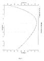
- Fig. 5 depicts the efficiency of the foregoing implementation of the antenna 200. As shown, the antenna 200 exhibits good efficiency across the WLAN band, notwithstanding the multiple polarization diversity of the antenna 200.
Landscapes
- Waveguide Aerials (AREA)
- Variable-Direction Aerials And Aerial Arrays (AREA)
Abstract
Description
- This patent application relates to an antenna apparatus. In particular, this patent application relates to an antenna having polarization diversity.
- The electric field of a propagating electromagnetic wave has two linear components that are orthogonal to one another. Typically, these components trace out an ellipse as a function of time. However, the electromagnetic wave might have only a single electric field component, in which case the electromagnetic wave is said to be linearly polarized.
- If an electromagnetic wave is linearly polarized, signal quality may be adversely affected by multipath signals, since many linearly polarized signals with different polarization might exist at the receiving antenna. A polarization diverse antenna can be used to improve signal transmission/reception quality in multipath environments since the signal strength received by such antennas can be greater than with a single linearly polarized antenna. A polarization diverse antenna can also be used to increase network capacity since multiple signals of the same frequency, but different polarizations, can be transmitted from and/or received at a single antenna.
- Conventional linear polarization diversity antennas may have two feed/receive lines that transmit/receive two respective orthogonal components of the electromagnetic wave. For example,
Zhang (US 6,593,891 ) describes a polarization diverse antenna that comprises a dielectric substrate having an upper conductive surface. A cross-shaped slot is formed in the upper conductive surface. The lower surface of the dielectric includes elongated conductive strips that are aligned with the arms of the slot, and a rectangular conductive portion that is aligned with the centre of the slot. The antenna also includes a pair of feed lines, each attached to a respective one of the conductive strips. - Alternately, a linear polarization diversity antenna may have a single feed/receive line, but have a complex structure to transmit/receive the orthogonal components of the electromagnetic wave. For instance,
Thudor (US 7,336,233 ) describes a polarization diverse antenna that comprises five slots that are arranged in a H-shaped structure on the upper surface of a dielectric substrate. A single feed line is disposed on the lower surface of the dielectric substrate, and is perpendicular to the centre slot. The antenna also includes a switching means that are positioned in the middle of each slot, except the middle slot. Similarly,Milyakh (US 7,358,916 ) describes a polarization diverse antenna that comprises four right-angled bent conductive strips that are disposed on a dielectric substrate. The antenna also includes a switching network comprising diodes that are formed between the ends of adjacent strips. A single feed line is connected between the diagonally opposite strips, at the bent portion thereof. - A common problem of dual-polarized antenna is the high possibility of crosstalk between the polarized components.
- In a first aspect, this patent application describes a three-fold polarization diversity antenna that comprises a slot-loaded patch, and a radiation member that is electromagnetically coupled to the slot-loaded patch. The radiation member extends through a plane of the slot-loaded patch.
- In a second aspect, this patent application describes a wireless communications device that comprises a radio transceiver section, and a three-fold polarization diversity antenna that is coupled to the radio transceiver section. The three-fold diversity antenna comprises a slot-loaded patch, and a radiation member that is electromagnetically coupled to the slot-loaded patch. The radiation member extends through a plane of the slot-loaded patch.
- The radiation member may be disposed at a substantially right angle to the plane of the slot-loaded patch. The slot-loaded patch may comprise a pair of intersecting slots that extend through a planar conductive layer, with the intersecting slots being disposed at a substantially right angle to each other. The radiation member may terminate at one end within a central portion of the slot-loaded patch, such that the one end is physically isolated from the slot-loaded patch.
- In one implementation, the slot-loaded patch comprises a cross-slot-shaped through-hole that extends through the planar conductive layer. The radiation member comprises a monopole that extends between a feed point and a centre of the cross-slot-shaped through-hole. The monopole may comprise a ground plane, and an elongate conductor that extends from the ground plane and terminates in the centre of the cross-slot-shaped through-hole. The ground plane may be substantially parallel to the planar conductive layer, with the elongate conductor being disposed at a substantially right angle to the planar conductive layer and the ground plane.
- As will become apparent, the three-fold polarization diversity antenna has a simple compact structure. The antenna also provides good isolation between the polarized components, and may be used in WLAN networks.
- Sample embodiments of the three-fold polarization diversity antenna and the wireless communications device will now be described, with reference to the accompanying drawings, in which:
-
Fig. 1 is a schematic diagram depicting certain functional components of the wireless communications device, including the three-fold polarization diversity antenna; -
Fig. 2a is a top perspective view of the three-fold polarization diversity antenna, depicting the slot-loaded patch, and the radiation member; -
Fig. 2b is a side elevation of the three-fold polarization diversity antenna; -
Fig. 3 depicts the measured return loss for a WLAN embodiment of the three-fold polarization diversity antenna; -
Fig. 4 depicts the radiation pattern of the three-fold polarization diversity antenna ofFig. 3 ; and -
Fig. 5 depicts the efficiency of the three-fold polarization diversity antenna ofFig. 3 . - Turning now to
Fig. 1 , there is shown awireless communications device 100 that is configured to operate within a wireless network. Preferably, thecommunications device 100 is a two-way wireless communications device. Depending on the exact functionality provided, thewireless communications device 100 may be configured as a wireless base station, a portable wireless modem, or a wireless data communication device, as examples. - As shown, the
wireless communications device 100 includes acommunication subsystem 102, and adata processing system 104 that is coupled to thecommunication subsystem 102. Thecommunication subsystem 102 performs communication functions, and includes awireless transmitter 106, awireless receiver 108, and aninternal antenna 200, a local oscillator (LOs) 110 and a digital signal processor (DSP) 112 connected to thetransmitter 106 and thereceiver 108. - Preferably, the
internal antenna 200 is a wide-band antenna that is configured for use with one or more of the application bands that are available within the wireless network. More preferably, theinternal antenna 200 is configured for use within a WLAN (IEEE 802.11x) network. Theinternal antenna 200 will be discussed in detail below, with reference toFigs. 2 to 5 . - The
data processing system 104 comprises amicroprocessor 114, aflash memory 116 and adata port 118. Theflash memory 116 includes signal processing instructions for theDSP 112, and may also include computer processing instructions for themicroprocessor 114. The computer processing instructions, when accessed from theflash memory 116 and executed by themicroprocessor 114 define an operating system that controls the overall operation of thecommunications device 100. Alternately, thedata processing system 104 may also include a volatile memory (RAM) 120. The computer processing instructions may be copied from theflash memory 116 into theRAM 120, and then accessed from theRAM 116 and executed by themicroprocessor 114. - The
data port 118 interfaces thewireless communications device 100 with a communications network, such as a wired or wireless local area network (LAN) or wide area network (WAN). Data packets that are received at thedata processing system 104 from the communications network via thedata port 118 are transferred by the operating system to thecommunication subsystem 102 for transmission as wireless electromagnetic signals over the wireless network. Wireless electromagnetic signals to be transmitted over the wireless network are processed by theDSP 112 and input to thetransmitter 106 for digital to analog conversion, frequency up conversion, and transmission over the wireless network via theinternal antenna 200. - Conversely, wireless electromagnetic signals that are received by the
internal antenna 200 from the wireless network are input to thereceiver 108, which performs common receiver functions such as frequency down conversion, and analog to digital (A/D) conversion, in preparation for more complex communication functions performed by theDSP 112. Data packets that are received at thedata processing system 104 from the DSP 112 are transmitted by the operating system over the communications network via thedata port 118. - Although the
communication subsystem 102 is depicting inFig. 1 having only onetransmitter 106 and onereceiver 108, thecommunication subsystem 102 may include additional transmitters and/or receivers, depending upon the range of frequency bands over which communication is desired. Similarly, although thecommunication subsystem 102 is depicted inFig. 1 with oneantenna 200, it should be understood that thewireless communications device 100 may instead comprise two or more of theantennas 200. Further, if thecommunication subsystem 102 includes more than oneDSP 112, the signals transmitted and received by the additional transmitter(s)/receiver(s) would preferably be processed by a different DSP than thetransmitter 106 and thereceiver 108. -
Figs. 2a and 2b depict the preferred structure of the three-foldpolarization diversity antenna 200. Theantenna 200 comprises a slot-loadedpatch antenna structure 202, and aradiation member 204 that is electromagnetically coupled to thepatch antenna structure 202. Thepatch antenna structure 202 comprises aconductive layer 206, and a slot-shaped aperture that extends through theconductive layer 206. Theconductive layer 206 typically is substantially planar, and may have a substantially square planar shape. Alternately, theconductive layer 206 may have rectangular, elliptical or circular planar shape. Further, theconductive layer 206 need not be planar, but may have an arcuate shape. - As shown, the slot-shaped aperture may comprise a pair of elongate
linear intersecting slots conductive layer 206, between the upper and lower surfaces thereof, thereby forming a cross-slot-shaped through-hole in theconductive layer 206. Preferably, the intersectingslots slots patch antenna structure 202 may comprise a single slot; or may comprise three linear intersecting slots oriented 120° with respect to each other. - The
radiation member 204 extends through a plane of the slot-loaded patch. Preferably, theradiation member 204 is disposed at a substantially right angle to the plane of the slot-loaded patch. Further, theradiation member 204 is configured as a grounded monopole, and comprises aplanar ground plane 210, and anelongate conductor 212. Theelongate conductor 212 is physically isolated from theground plane 210, and extends from theground plane 210, terminating proximate the centre portion of the slot-shaped aperture, between the upper and lower surfaces of theconductive layer 206. With this configuration, the field distributions produced by the antenna will be symmetric. Alternately, however, for non-symmetric field distributions, theelongate conductor 212 may terminate at a position that is off-centre. Preferably, theelongate conductor 212 extends vertically upwards through theground plane 210 towards the slot-shaped aperture, from afeed point 214 that is disposed below theground plane 210. - The
antenna 200 may include a dielectric substrate (not shown) that is disposed between theconductive layer 206 and theground plane 210. In this implementation, theconductive layer 206 and theground plane 210 are disposed on opposite faces of the dielectric substrate. Further, the dielectric substrate is configured with a through-hole through which theelongate conductor 212 extends between theground plane 210 and theconductive layer 206. - As shown, the
ground plane 210 may be oriented substantially parallel to the planarconductive layer 206. With this configuration, theelongate conductor 212 is disposed at a substantially right angle to the planarconductive layer 206 and theground plane 210. Alternately, however, the planarconductive layer 206 may be inclined relative to theground plane 210 at an angle other than a right angle. - The end of the
elongate conductor 212 that is opposite the feed point 214 ("terminal end") may be disposed within theregion 216 of the intersection of the intersectingslots elongate conductor 212 is physically isolated from the slot-loaded patch. As a result, theradiation member 204 is electromagnetically coupled to the slot-loaded patch. - Alternately, the
radiation member 204 may be configured as a dipole that is electromagnetically coupled at the opposite ends thereof to respectivepatch antenna structures 202. As in the previous example, theradiation member 204 may comprise an elongate member whose opposite ends are physically isolated from the slot-loaded patches and terminate proximate the centre portion of the respective slot-shaped apertures. - As discussed above, the
communication subsystem 102 may be provided with a plurality of theantennas 200. In a preferred implementation, theconductive layer 206 comprises a plurality of slot-shaped apertures that are disposed uniformly on a common planarconductive layer 206. In this variation, theantennas 200 may be disposed uniformly over theconductive layer 206, thereby providing a planar antenna array. Alternately, theconductive layer 206 may have a cylindrical configuration, with the plurality of slot-shaped apertures being disposed uniformly over the cylindricalconductive layer 206. In this latter variation, preferably eachradiation member 204 is disposed at a substantially right angle to the plane of the associated slot-shaped aperture, at the centre portion of the associated slot-shaped aperture. - As is known to persons of skill in the art, the length of a conventional monopole is one-quarter of the wavelength of the fundamental. However, due to the electromagnetic coupling between the
radiation member 204 and the slot-loaded patch, the length of theelongate conductor 212 is less than one-quarter of the wavelength (when theradiation member 204 is configured as a grounded monopole). As a result, the height of theantenna 200 may be less than a conventional monopole antenna having the same minimum resonant frequency. Further, theantenna 200 does not exhibit the power loss that would otherwise occur if theradiation member 204 was electrically connected to the slot-loaded patch. - As is also known to persons of skill in the art, the electric field of a conventional monopole is polarized in the direction of the monopole. Therefore, the electric field of the
antenna 200 includes a vertically-polarized electric field. However, due to the electromagnetic coupling between theradiation member 204 and the slot-loaded patch, theradiation member 204 induces electric currents in the slot-loaded patch. Since the intersectingslots antenna 200 also includes two perpendicular horizontally-polarized electric fields. As a result, the electromagnetic field produced by theantenna 200 has three orthogonal polarized electric fields (i.e. three-fold polarization diversity). -
Fig. 3 depicts the measured return loss for one implementation of theantenna 200. In this implementation, theconductive layer 206 and theground plane 210 are substantially square, and the dimensions of theantenna 200 are as follows: - L1 = 75 mm
- L2 = 23 mm
- L3 = 28 mm
- W= 1.5 mm
- H = 10 mm
- L1 is the length of each side of the
ground plane 210; - L2 is the length of each side of the
conductive layer 206; - L3 is the length of each of the intersecting
slots - W is the width of each of the intersecting
slots - H is the length of the
elongate conductor 212. - As shown, the frequency range of the
antenna 200 covers WLAN IEEE 802.11 b/g (4.9 - 6 GHz). -
Fig. 4 depicts the radiation pattern of the foregoing implementation of theantenna 200, measured at 5.5 GHz. As shown, at this WLAN frequency the electromagnetic field of theantenna 200 has two perpendicular horizontally-polarized electric fields, with good isolation between the electric fields. -
Fig. 5 depicts the efficiency of the foregoing implementation of theantenna 200. As shown, theantenna 200 exhibits good efficiency across the WLAN band, notwithstanding the multiple polarization diversity of theantenna 200.
Claims (11)
- A three-fold polarization diversity antenna comprising:a slot-loaded patch comprising a slot extending through a conductive layer; anda radiation member electromagnetically coupled to the slot-loaded patch, the radiation member extending through a plane of the slot-loaded patch.
- The three-fold polarization diversity antenna according to Claim 1, wherein the radiation member is disposed at a substantially right angle to the plane of the slot-loaded patch.
- The three-fold polarization diversity antenna according to Claim 1 or Claim 2, wherein the slot-loaded patch comprises a pair of intersecting slots extending through a planar conductive layer, the intersecting slots being disposed at a substantially right angle to each other.
- The three-fold polarization diversity antenna according to Claim 1, wherein the radiation member terminates at one end within a central portion of the slot-loaded patch, the one end being physically isolated from the slot-loaded patch.
- The three-fold polarization diversity antenna according to Claim 1, wherein the slot-loaded patch comprises a cross-slot-shaped through-hole extending through a planar conductive layer.
- The three-fold polarization diversity antenna according to Claim 5, wherein the radiation member comprises a monopole that extends between a feed point and a centre of the cross-slot-shaped through-hole.
- The three-fold polarization diversity antenna according to Claim 5, wherein the monopole comprises a ground plane, and an elongate conductor that extends from the ground plane and terminates in a centre of the cross-slot-shaped through-hole.
- The three-fold polarization diversity antenna according to Claim 7, wherein the ground plane is substantially parallel to the planar conductive layer.
- The three-fold polarization diversity antenna according to Claim 8, wherein the elongate conductor is disposed at a substantially right angle to the planar conductive layer and the ground plane.
- A wireless communications device comprising:a radio transceiver section; anda three-fold polarization diversity antenna according to any one of Claims 1 to 9.
- The communications device according to Claim 10, configured as a wireless base station.
Priority Applications (1)
| Application Number | Priority Date | Filing Date | Title |
|---|---|---|---|
| EP20080166982 EP2178169B1 (en) | 2008-10-17 | 2008-10-17 | Three-fold polarization diversity antenna |
Applications Claiming Priority (1)
| Application Number | Priority Date | Filing Date | Title |
|---|---|---|---|
| EP20080166982 EP2178169B1 (en) | 2008-10-17 | 2008-10-17 | Three-fold polarization diversity antenna |
Publications (2)
| Publication Number | Publication Date |
|---|---|
| EP2178169A1 true EP2178169A1 (en) | 2010-04-21 |
| EP2178169B1 EP2178169B1 (en) | 2014-06-04 |
Family
ID=40032610
Family Applications (1)
| Application Number | Title | Priority Date | Filing Date |
|---|---|---|---|
| EP20080166982 Active EP2178169B1 (en) | 2008-10-17 | 2008-10-17 | Three-fold polarization diversity antenna |
Country Status (1)
| Country | Link |
|---|---|
| EP (1) | EP2178169B1 (en) |
Cited By (1)
| Publication number | Priority date | Publication date | Assignee | Title |
|---|---|---|---|---|
| CN102610908A (en) * | 2012-03-01 | 2012-07-25 | 西安电子科技大学 | Ultra wide band four-tape circularly polarized antenna |
Citations (3)
| Publication number | Priority date | Publication date | Assignee | Title |
|---|---|---|---|---|
| US4242685A (en) * | 1979-04-27 | 1980-12-30 | Ball Corporation | Slotted cavity antenna |
| US4443802A (en) | 1981-04-22 | 1984-04-17 | University Of Illinois Foundation | Stripline fed hybrid slot antenna |
| US4684953A (en) * | 1984-01-09 | 1987-08-04 | Mcdonnell Douglas Corporation | Reduced height monopole/crossed slot antenna |
-
2008
- 2008-10-17 EP EP20080166982 patent/EP2178169B1/en active Active
Patent Citations (3)
| Publication number | Priority date | Publication date | Assignee | Title |
|---|---|---|---|---|
| US4242685A (en) * | 1979-04-27 | 1980-12-30 | Ball Corporation | Slotted cavity antenna |
| US4443802A (en) | 1981-04-22 | 1984-04-17 | University Of Illinois Foundation | Stripline fed hybrid slot antenna |
| US4684953A (en) * | 1984-01-09 | 1987-08-04 | Mcdonnell Douglas Corporation | Reduced height monopole/crossed slot antenna |
Cited By (1)
| Publication number | Priority date | Publication date | Assignee | Title |
|---|---|---|---|---|
| CN102610908A (en) * | 2012-03-01 | 2012-07-25 | 西安电子科技大学 | Ultra wide band four-tape circularly polarized antenna |
Also Published As
| Publication number | Publication date |
|---|---|
| EP2178169B1 (en) | 2014-06-04 |
Similar Documents
| Publication | Publication Date | Title |
|---|---|---|
| EP3975337B1 (en) | Antenna unit and terminal device | |
| Malviya et al. | A 2× 2 dual-band MIMO antenna with polarization diversity for wireless applications | |
| US8854270B2 (en) | Hybrid multi-antenna system and wireless communication apparatus using the same | |
| EP2695235B1 (en) | Two-polarization switched-beam antenna for wireless communication systems | |
| Parchin et al. | A closely spaced dual-band MIMO patch antenna with reduced mutual coupling for 4G/5G applications | |
| US8878737B2 (en) | Single feed planar dual-polarization multi-loop element antenna | |
| CN105071044B (en) | A kind of small high isolation degree dual polarization medium resonator antenna | |
| EP2617098B1 (en) | Antenna for diversity operation | |
| CN112968281B (en) | Dual-polarized filtering antenna unit and dual-polarized filtering antenna array | |
| CN110011026B (en) | Antenna unit, antenna array and base station | |
| US8203498B2 (en) | Three-fold polarization diversity antenna | |
| Ren et al. | Coexist design of sub-6GHz and millimeter-wave antennas for 5G mobile terminals | |
| CN216120726U (en) | Small circularly polarized Vivaldi antenna and mobile communication system | |
| CN113937473A (en) | Small circularly polarized Vivaldi antenna, control method and mobile communication system | |
| Babu et al. | Tri-band MIMO antenna for WLAN, WiMAX and defence system & radio astronomy applications | |
| CN115313028B (en) | Ultra-wideband antenna applied to 2G/3G/4G/5G frequency bands | |
| WO2021083223A1 (en) | Antenna unit and electronic device | |
| CN113594718B (en) | Antenna array and wireless communication device | |
| Malviya et al. | MIMO antenna design with low ECC for mmWave | |
| EP2178169B1 (en) | Three-fold polarization diversity antenna | |
| CN209948040U (en) | Dual-frequency dual-horizontal polarization omnidirectional antenna | |
| WO1998027614A1 (en) | Antenna with diversity transformation | |
| CN110828988B (en) | Antenna unit and electronic equipment | |
| Parchin et al. | A compact design of orthogonally dual-polarized antenna for ultra-wideband, imaging, and radar applications | |
| US11923620B1 (en) | Compact ceramic chip antenna array based on ultra-wide band three-dimensional direction finding |
Legal Events
| Date | Code | Title | Description |
|---|---|---|---|
| PUAI | Public reference made under article 153(3) epc to a published international application that has entered the european phase |
Free format text: ORIGINAL CODE: 0009012 |
|
| 17P | Request for examination filed |
Effective date: 20081017 |
|
| AK | Designated contracting states |
Kind code of ref document: A1 Designated state(s): AT BE BG CH CY CZ DE DK EE ES FI FR GB GR HR HU IE IS IT LI LT LU LV MC MT NL NO PL PT RO SE SI SK TR |
|
| AX | Request for extension of the european patent |
Extension state: AL BA MK RS |
|
| AKX | Designation fees paid |
Designated state(s): AT BE BG CH CY CZ DE DK EE ES FI FR GB GR HR HU IE IS IT LI LT LU LV MC MT NL NO PL PT RO SE SI SK TR |
|
| AXX | Extension fees paid |
Extension state: MK Payment date: 20081017 Extension state: BA Payment date: 20081017 Extension state: AL Payment date: 20081017 Extension state: RS Payment date: 20081017 |
|
| 17Q | First examination report despatched |
Effective date: 20130103 |
|
| RAP1 | Party data changed (applicant data changed or rights of an application transferred) |
Owner name: BLACKBERRY LIMITED |
|
| RAP1 | Party data changed (applicant data changed or rights of an application transferred) |
Owner name: BLACKBERRY LIMITED |
|
| GRAP | Despatch of communication of intention to grant a patent |
Free format text: ORIGINAL CODE: EPIDOSNIGR1 |
|
| INTG | Intention to grant announced |
Effective date: 20131220 |
|
| GRAS | Grant fee paid |
Free format text: ORIGINAL CODE: EPIDOSNIGR3 |
|
| GRAA | (expected) grant |
Free format text: ORIGINAL CODE: 0009210 |
|
| AK | Designated contracting states |
Kind code of ref document: B1 Designated state(s): AT BE BG CH CY CZ DE DK EE ES FI FR GB GR HR HU IE IS IT LI LT LU LV MC MT NL NO PL PT RO SE SI SK TR |
|
| AX | Request for extension of the european patent |
Extension state: AL BA MK RS |
|
| REG | Reference to a national code |
Ref country code: GB Ref legal event code: FG4D |
|
| REG | Reference to a national code |
Ref country code: CH Ref legal event code: EP |
|
| REG | Reference to a national code |
Ref country code: AT Ref legal event code: REF Ref document number: 671553 Country of ref document: AT Kind code of ref document: T Effective date: 20140615 |
|
| REG | Reference to a national code |
Ref country code: IE Ref legal event code: FG4D |
|
| REG | Reference to a national code |
Ref country code: DE Ref legal event code: R096 Ref document number: 602008032542 Country of ref document: DE Effective date: 20140717 |
|
| REG | Reference to a national code |
Ref country code: AT Ref legal event code: MK05 Ref document number: 671553 Country of ref document: AT Kind code of ref document: T Effective date: 20140604 |
|
| REG | Reference to a national code |
Ref country code: NL Ref legal event code: VDEP Effective date: 20140604 |
|
| PG25 | Lapsed in a contracting state [announced via postgrant information from national office to epo] |
Ref country code: LT Free format text: LAPSE BECAUSE OF FAILURE TO SUBMIT A TRANSLATION OF THE DESCRIPTION OR TO PAY THE FEE WITHIN THE PRESCRIBED TIME-LIMIT Effective date: 20140604 Ref country code: CY Free format text: LAPSE BECAUSE OF FAILURE TO SUBMIT A TRANSLATION OF THE DESCRIPTION OR TO PAY THE FEE WITHIN THE PRESCRIBED TIME-LIMIT Effective date: 20140604 Ref country code: FI Free format text: LAPSE BECAUSE OF FAILURE TO SUBMIT A TRANSLATION OF THE DESCRIPTION OR TO PAY THE FEE WITHIN THE PRESCRIBED TIME-LIMIT Effective date: 20140604 Ref country code: GR Free format text: LAPSE BECAUSE OF FAILURE TO SUBMIT A TRANSLATION OF THE DESCRIPTION OR TO PAY THE FEE WITHIN THE PRESCRIBED TIME-LIMIT Effective date: 20140905 Ref country code: NO Free format text: LAPSE BECAUSE OF FAILURE TO SUBMIT A TRANSLATION OF THE DESCRIPTION OR TO PAY THE FEE WITHIN THE PRESCRIBED TIME-LIMIT Effective date: 20140904 |
|
| REG | Reference to a national code |
Ref country code: LT Ref legal event code: MG4D |
|
| PG25 | Lapsed in a contracting state [announced via postgrant information from national office to epo] |
Ref country code: SE Free format text: LAPSE BECAUSE OF FAILURE TO SUBMIT A TRANSLATION OF THE DESCRIPTION OR TO PAY THE FEE WITHIN THE PRESCRIBED TIME-LIMIT Effective date: 20140604 Ref country code: AT Free format text: LAPSE BECAUSE OF FAILURE TO SUBMIT A TRANSLATION OF THE DESCRIPTION OR TO PAY THE FEE WITHIN THE PRESCRIBED TIME-LIMIT Effective date: 20140604 Ref country code: LV Free format text: LAPSE BECAUSE OF FAILURE TO SUBMIT A TRANSLATION OF THE DESCRIPTION OR TO PAY THE FEE WITHIN THE PRESCRIBED TIME-LIMIT Effective date: 20140604 Ref country code: HR Free format text: LAPSE BECAUSE OF FAILURE TO SUBMIT A TRANSLATION OF THE DESCRIPTION OR TO PAY THE FEE WITHIN THE PRESCRIBED TIME-LIMIT Effective date: 20140604 |
|
| PG25 | Lapsed in a contracting state [announced via postgrant information from national office to epo] |
Ref country code: SK Free format text: LAPSE BECAUSE OF FAILURE TO SUBMIT A TRANSLATION OF THE DESCRIPTION OR TO PAY THE FEE WITHIN THE PRESCRIBED TIME-LIMIT Effective date: 20140604 Ref country code: CZ Free format text: LAPSE BECAUSE OF FAILURE TO SUBMIT A TRANSLATION OF THE DESCRIPTION OR TO PAY THE FEE WITHIN THE PRESCRIBED TIME-LIMIT Effective date: 20140604 Ref country code: RO Free format text: LAPSE BECAUSE OF FAILURE TO SUBMIT A TRANSLATION OF THE DESCRIPTION OR TO PAY THE FEE WITHIN THE PRESCRIBED TIME-LIMIT Effective date: 20140604 Ref country code: ES Free format text: LAPSE BECAUSE OF FAILURE TO SUBMIT A TRANSLATION OF THE DESCRIPTION OR TO PAY THE FEE WITHIN THE PRESCRIBED TIME-LIMIT Effective date: 20140604 Ref country code: PT Free format text: LAPSE BECAUSE OF FAILURE TO SUBMIT A TRANSLATION OF THE DESCRIPTION OR TO PAY THE FEE WITHIN THE PRESCRIBED TIME-LIMIT Effective date: 20141006 Ref country code: EE Free format text: LAPSE BECAUSE OF FAILURE TO SUBMIT A TRANSLATION OF THE DESCRIPTION OR TO PAY THE FEE WITHIN THE PRESCRIBED TIME-LIMIT Effective date: 20140604 |
|
| PG25 | Lapsed in a contracting state [announced via postgrant information from national office to epo] |
Ref country code: IS Free format text: LAPSE BECAUSE OF FAILURE TO SUBMIT A TRANSLATION OF THE DESCRIPTION OR TO PAY THE FEE WITHIN THE PRESCRIBED TIME-LIMIT Effective date: 20141004 Ref country code: PL Free format text: LAPSE BECAUSE OF FAILURE TO SUBMIT A TRANSLATION OF THE DESCRIPTION OR TO PAY THE FEE WITHIN THE PRESCRIBED TIME-LIMIT Effective date: 20140604 Ref country code: NL Free format text: LAPSE BECAUSE OF FAILURE TO SUBMIT A TRANSLATION OF THE DESCRIPTION OR TO PAY THE FEE WITHIN THE PRESCRIBED TIME-LIMIT Effective date: 20140604 |
|
| REG | Reference to a national code |
Ref country code: DE Ref legal event code: R097 Ref document number: 602008032542 Country of ref document: DE |
|
| PLBE | No opposition filed within time limit |
Free format text: ORIGINAL CODE: 0009261 |
|
| STAA | Information on the status of an ep patent application or granted ep patent |
Free format text: STATUS: NO OPPOSITION FILED WITHIN TIME LIMIT |
|
| PG25 | Lapsed in a contracting state [announced via postgrant information from national office to epo] |
Ref country code: DK Free format text: LAPSE BECAUSE OF FAILURE TO SUBMIT A TRANSLATION OF THE DESCRIPTION OR TO PAY THE FEE WITHIN THE PRESCRIBED TIME-LIMIT Effective date: 20140604 Ref country code: IT Free format text: LAPSE BECAUSE OF FAILURE TO SUBMIT A TRANSLATION OF THE DESCRIPTION OR TO PAY THE FEE WITHIN THE PRESCRIBED TIME-LIMIT Effective date: 20140604 |
|
| 26N | No opposition filed |
Effective date: 20150305 |
|
| PG25 | Lapsed in a contracting state [announced via postgrant information from national office to epo] |
Ref country code: MC Free format text: LAPSE BECAUSE OF FAILURE TO SUBMIT A TRANSLATION OF THE DESCRIPTION OR TO PAY THE FEE WITHIN THE PRESCRIBED TIME-LIMIT Effective date: 20140604 Ref country code: LU Free format text: LAPSE BECAUSE OF FAILURE TO SUBMIT A TRANSLATION OF THE DESCRIPTION OR TO PAY THE FEE WITHIN THE PRESCRIBED TIME-LIMIT Effective date: 20141017 |
|
| REG | Reference to a national code |
Ref country code: CH Ref legal event code: PL |
|
| REG | Reference to a national code |
Ref country code: DE Ref legal event code: R097 Ref document number: 602008032542 Country of ref document: DE Effective date: 20150305 |
|
| REG | Reference to a national code |
Ref country code: IE Ref legal event code: MM4A |
|
| PG25 | Lapsed in a contracting state [announced via postgrant information from national office to epo] |
Ref country code: LI Free format text: LAPSE BECAUSE OF NON-PAYMENT OF DUE FEES Effective date: 20141031 Ref country code: CH Free format text: LAPSE BECAUSE OF NON-PAYMENT OF DUE FEES Effective date: 20141031 Ref country code: SI Free format text: LAPSE BECAUSE OF FAILURE TO SUBMIT A TRANSLATION OF THE DESCRIPTION OR TO PAY THE FEE WITHIN THE PRESCRIBED TIME-LIMIT Effective date: 20140604 |
|
| REG | Reference to a national code |
Ref country code: FR Ref legal event code: PLFP Year of fee payment: 8 |
|
| PG25 | Lapsed in a contracting state [announced via postgrant information from national office to epo] |
Ref country code: IE Free format text: LAPSE BECAUSE OF NON-PAYMENT OF DUE FEES Effective date: 20141017 |
|
| PG25 | Lapsed in a contracting state [announced via postgrant information from national office to epo] |
Ref country code: BG Free format text: LAPSE BECAUSE OF FAILURE TO SUBMIT A TRANSLATION OF THE DESCRIPTION OR TO PAY THE FEE WITHIN THE PRESCRIBED TIME-LIMIT Effective date: 20140604 |
|
| PG25 | Lapsed in a contracting state [announced via postgrant information from national office to epo] |
Ref country code: MT Free format text: LAPSE BECAUSE OF FAILURE TO SUBMIT A TRANSLATION OF THE DESCRIPTION OR TO PAY THE FEE WITHIN THE PRESCRIBED TIME-LIMIT Effective date: 20140604 Ref country code: HU Free format text: LAPSE BECAUSE OF FAILURE TO SUBMIT A TRANSLATION OF THE DESCRIPTION OR TO PAY THE FEE WITHIN THE PRESCRIBED TIME-LIMIT; INVALID AB INITIO Effective date: 20081017 Ref country code: TR Free format text: LAPSE BECAUSE OF FAILURE TO SUBMIT A TRANSLATION OF THE DESCRIPTION OR TO PAY THE FEE WITHIN THE PRESCRIBED TIME-LIMIT Effective date: 20140604 Ref country code: BE Free format text: LAPSE BECAUSE OF FAILURE TO SUBMIT A TRANSLATION OF THE DESCRIPTION OR TO PAY THE FEE WITHIN THE PRESCRIBED TIME-LIMIT Effective date: 20140604 |
|
| REG | Reference to a national code |
Ref country code: FR Ref legal event code: PLFP Year of fee payment: 9 |
|
| REG | Reference to a national code |
Ref country code: FR Ref legal event code: PLFP Year of fee payment: 10 |
|
| REG | Reference to a national code |
Ref country code: FR Ref legal event code: PLFP Year of fee payment: 11 |
|
| REG | Reference to a national code |
Ref country code: DE Ref legal event code: R082 Ref document number: 602008032542 Country of ref document: DE Ref country code: DE Ref legal event code: R081 Ref document number: 602008032542 Country of ref document: DE Owner name: MALIKIE INNOVATIONS LTD., IE Free format text: FORMER OWNER: BLACKBERRY LTD., WATERLOO, ONTARIO, CA |
|
| PGFP | Annual fee paid to national office [announced via postgrant information from national office to epo] |
Ref country code: DE Payment date: 20251028 Year of fee payment: 18 |
|
| PGFP | Annual fee paid to national office [announced via postgrant information from national office to epo] |
Ref country code: GB Payment date: 20251023 Year of fee payment: 18 |
|
| PGFP | Annual fee paid to national office [announced via postgrant information from national office to epo] |
Ref country code: FR Payment date: 20251027 Year of fee payment: 18 |