EP2177900A2 - Conductive tape for crack detection - Google Patents
Conductive tape for crack detection Download PDFInfo
- Publication number
- EP2177900A2 EP2177900A2 EP20090252425 EP09252425A EP2177900A2 EP 2177900 A2 EP2177900 A2 EP 2177900A2 EP 20090252425 EP20090252425 EP 20090252425 EP 09252425 A EP09252425 A EP 09252425A EP 2177900 A2 EP2177900 A2 EP 2177900A2
- Authority
- EP
- European Patent Office
- Prior art keywords
- tape
- fibers
- electrically conductive
- structural fibers
- carbon nanotubes
- Prior art date
- Legal status (The legal status is an assumption and is not a legal conclusion. Google has not performed a legal analysis and makes no representation as to the accuracy of the status listed.)
- Granted
Links
Images


Classifications
-
- H—ELECTRICITY
- H01—ELECTRIC ELEMENTS
- H01B—CABLES; CONDUCTORS; INSULATORS; SELECTION OF MATERIALS FOR THEIR CONDUCTIVE, INSULATING OR DIELECTRIC PROPERTIES
- H01B1/00—Conductors or conductive bodies characterised by the conductive materials; Selection of materials as conductors
- H01B1/20—Conductive material dispersed in non-conductive organic material
- H01B1/24—Conductive material dispersed in non-conductive organic material the conductive material comprising carbon-silicon compounds, carbon or silicon
-
- G—PHYSICS
- G01—MEASURING; TESTING
- G01M—TESTING STATIC OR DYNAMIC BALANCE OF MACHINES OR STRUCTURES; TESTING OF STRUCTURES OR APPARATUS, NOT OTHERWISE PROVIDED FOR
- G01M5/00—Investigating the elasticity of structures, e.g. deflection of bridges or air-craft wings
- G01M5/0016—Investigating the elasticity of structures, e.g. deflection of bridges or air-craft wings of aircraft wings or blades
-
- G—PHYSICS
- G01—MEASURING; TESTING
- G01M—TESTING STATIC OR DYNAMIC BALANCE OF MACHINES OR STRUCTURES; TESTING OF STRUCTURES OR APPARATUS, NOT OTHERWISE PROVIDED FOR
- G01M5/00—Investigating the elasticity of structures, e.g. deflection of bridges or air-craft wings
- G01M5/0033—Investigating the elasticity of structures, e.g. deflection of bridges or air-craft wings by determining damage, crack or wear
-
- G—PHYSICS
- G01—MEASURING; TESTING
- G01M—TESTING STATIC OR DYNAMIC BALANCE OF MACHINES OR STRUCTURES; TESTING OF STRUCTURES OR APPARATUS, NOT OTHERWISE PROVIDED FOR
- G01M5/00—Investigating the elasticity of structures, e.g. deflection of bridges or air-craft wings
- G01M5/0083—Investigating the elasticity of structures, e.g. deflection of bridges or air-craft wings by measuring variation of impedance, e.g. resistance, capacitance, induction
-
- H—ELECTRICITY
- H01—ELECTRIC ELEMENTS
- H01B—CABLES; CONDUCTORS; INSULATORS; SELECTION OF MATERIALS FOR THEIR CONDUCTIVE, INSULATING OR DIELECTRIC PROPERTIES
- H01B1/00—Conductors or conductive bodies characterised by the conductive materials; Selection of materials as conductors
- H01B1/20—Conductive material dispersed in non-conductive organic material
- H01B1/22—Conductive material dispersed in non-conductive organic material the conductive material comprising metals or alloys
-
- G—PHYSICS
- G01—MEASURING; TESTING
- G01N—INVESTIGATING OR ANALYSING MATERIALS BY DETERMINING THEIR CHEMICAL OR PHYSICAL PROPERTIES
- G01N2203/00—Investigating strength properties of solid materials by application of mechanical stress
- G01N2203/0058—Kind of property studied
- G01N2203/006—Crack, flaws, fracture or rupture
- G01N2203/0062—Crack or flaws
-
- G—PHYSICS
- G01—MEASURING; TESTING
- G01N—INVESTIGATING OR ANALYSING MATERIALS BY DETERMINING THEIR CHEMICAL OR PHYSICAL PROPERTIES
- G01N2203/00—Investigating strength properties of solid materials by application of mechanical stress
- G01N2203/02—Details not specific for a particular testing method
- G01N2203/06—Indicating or recording means; Sensing means
- G01N2203/0664—Indicating or recording means; Sensing means using witness specimens
-
- Y—GENERAL TAGGING OF NEW TECHNOLOGICAL DEVELOPMENTS; GENERAL TAGGING OF CROSS-SECTIONAL TECHNOLOGIES SPANNING OVER SEVERAL SECTIONS OF THE IPC; TECHNICAL SUBJECTS COVERED BY FORMER USPC CROSS-REFERENCE ART COLLECTIONS [XRACs] AND DIGESTS
- Y10—TECHNICAL SUBJECTS COVERED BY FORMER USPC
- Y10T—TECHNICAL SUBJECTS COVERED BY FORMER US CLASSIFICATION
- Y10T156/00—Adhesive bonding and miscellaneous chemical manufacture
- Y10T156/10—Methods of surface bonding and/or assembly therefor
-
- Y—GENERAL TAGGING OF NEW TECHNOLOGICAL DEVELOPMENTS; GENERAL TAGGING OF CROSS-SECTIONAL TECHNOLOGIES SPANNING OVER SEVERAL SECTIONS OF THE IPC; TECHNICAL SUBJECTS COVERED BY FORMER USPC CROSS-REFERENCE ART COLLECTIONS [XRACs] AND DIGESTS
- Y10—TECHNICAL SUBJECTS COVERED BY FORMER USPC
- Y10T—TECHNICAL SUBJECTS COVERED BY FORMER US CLASSIFICATION
- Y10T428/00—Stock material or miscellaneous articles
- Y10T428/249921—Web or sheet containing structurally defined element or component
-
- Y—GENERAL TAGGING OF NEW TECHNOLOGICAL DEVELOPMENTS; GENERAL TAGGING OF CROSS-SECTIONAL TECHNOLOGIES SPANNING OVER SEVERAL SECTIONS OF THE IPC; TECHNICAL SUBJECTS COVERED BY FORMER USPC CROSS-REFERENCE ART COLLECTIONS [XRACs] AND DIGESTS
- Y10—TECHNICAL SUBJECTS COVERED BY FORMER USPC
- Y10T—TECHNICAL SUBJECTS COVERED BY FORMER US CLASSIFICATION
- Y10T428/00—Stock material or miscellaneous articles
- Y10T428/249921—Web or sheet containing structurally defined element or component
- Y10T428/249924—Noninterengaged fiber-containing paper-free web or sheet which is not of specified porosity
-
- Y—GENERAL TAGGING OF NEW TECHNOLOGICAL DEVELOPMENTS; GENERAL TAGGING OF CROSS-SECTIONAL TECHNOLOGIES SPANNING OVER SEVERAL SECTIONS OF THE IPC; TECHNICAL SUBJECTS COVERED BY FORMER USPC CROSS-REFERENCE ART COLLECTIONS [XRACs] AND DIGESTS
- Y10—TECHNICAL SUBJECTS COVERED BY FORMER USPC
- Y10T—TECHNICAL SUBJECTS COVERED BY FORMER US CLASSIFICATION
- Y10T428/00—Stock material or miscellaneous articles
- Y10T428/249921—Web or sheet containing structurally defined element or component
- Y10T428/249924—Noninterengaged fiber-containing paper-free web or sheet which is not of specified porosity
- Y10T428/249933—Fiber embedded in or on the surface of a natural or synthetic rubber matrix
- Y10T428/249938—Composite or conjugate fiber [e.g., fiber contains more than one chemically different material in monofilament or multifilament form, etc.]
-
- Y—GENERAL TAGGING OF NEW TECHNOLOGICAL DEVELOPMENTS; GENERAL TAGGING OF CROSS-SECTIONAL TECHNOLOGIES SPANNING OVER SEVERAL SECTIONS OF THE IPC; TECHNICAL SUBJECTS COVERED BY FORMER USPC CROSS-REFERENCE ART COLLECTIONS [XRACs] AND DIGESTS
- Y10—TECHNICAL SUBJECTS COVERED BY FORMER USPC
- Y10T—TECHNICAL SUBJECTS COVERED BY FORMER US CLASSIFICATION
- Y10T428/00—Stock material or miscellaneous articles
- Y10T428/249921—Web or sheet containing structurally defined element or component
- Y10T428/249924—Noninterengaged fiber-containing paper-free web or sheet which is not of specified porosity
- Y10T428/24994—Fiber embedded in or on the surface of a polymeric matrix
-
- Y—GENERAL TAGGING OF NEW TECHNOLOGICAL DEVELOPMENTS; GENERAL TAGGING OF CROSS-SECTIONAL TECHNOLOGIES SPANNING OVER SEVERAL SECTIONS OF THE IPC; TECHNICAL SUBJECTS COVERED BY FORMER USPC CROSS-REFERENCE ART COLLECTIONS [XRACs] AND DIGESTS
- Y10—TECHNICAL SUBJECTS COVERED BY FORMER USPC
- Y10T—TECHNICAL SUBJECTS COVERED BY FORMER US CLASSIFICATION
- Y10T428/00—Stock material or miscellaneous articles
- Y10T428/28—Web or sheet containing structurally defined element or component and having an adhesive outermost layer
-
- Y—GENERAL TAGGING OF NEW TECHNOLOGICAL DEVELOPMENTS; GENERAL TAGGING OF CROSS-SECTIONAL TECHNOLOGIES SPANNING OVER SEVERAL SECTIONS OF THE IPC; TECHNICAL SUBJECTS COVERED BY FORMER USPC CROSS-REFERENCE ART COLLECTIONS [XRACs] AND DIGESTS
- Y10—TECHNICAL SUBJECTS COVERED BY FORMER USPC
- Y10T—TECHNICAL SUBJECTS COVERED BY FORMER US CLASSIFICATION
- Y10T428/00—Stock material or miscellaneous articles
- Y10T428/29—Coated or structually defined flake, particle, cell, strand, strand portion, rod, filament, macroscopic fiber or mass thereof
- Y10T428/2913—Rod, strand, filament or fiber
-
- Y—GENERAL TAGGING OF NEW TECHNOLOGICAL DEVELOPMENTS; GENERAL TAGGING OF CROSS-SECTIONAL TECHNOLOGIES SPANNING OVER SEVERAL SECTIONS OF THE IPC; TECHNICAL SUBJECTS COVERED BY FORMER USPC CROSS-REFERENCE ART COLLECTIONS [XRACs] AND DIGESTS
- Y10—TECHNICAL SUBJECTS COVERED BY FORMER USPC
- Y10T—TECHNICAL SUBJECTS COVERED BY FORMER US CLASSIFICATION
- Y10T428/00—Stock material or miscellaneous articles
- Y10T428/29—Coated or structually defined flake, particle, cell, strand, strand portion, rod, filament, macroscopic fiber or mass thereof
- Y10T428/2913—Rod, strand, filament or fiber
- Y10T428/2915—Rod, strand, filament or fiber including textile, cloth or fabric
-
- Y—GENERAL TAGGING OF NEW TECHNOLOGICAL DEVELOPMENTS; GENERAL TAGGING OF CROSS-SECTIONAL TECHNOLOGIES SPANNING OVER SEVERAL SECTIONS OF THE IPC; TECHNICAL SUBJECTS COVERED BY FORMER USPC CROSS-REFERENCE ART COLLECTIONS [XRACs] AND DIGESTS
- Y10—TECHNICAL SUBJECTS COVERED BY FORMER USPC
- Y10T—TECHNICAL SUBJECTS COVERED BY FORMER US CLASSIFICATION
- Y10T428/00—Stock material or miscellaneous articles
- Y10T428/29—Coated or structually defined flake, particle, cell, strand, strand portion, rod, filament, macroscopic fiber or mass thereof
- Y10T428/2913—Rod, strand, filament or fiber
- Y10T428/2916—Rod, strand, filament or fiber including boron or compound thereof [not as steel]
-
- Y—GENERAL TAGGING OF NEW TECHNOLOGICAL DEVELOPMENTS; GENERAL TAGGING OF CROSS-SECTIONAL TECHNOLOGIES SPANNING OVER SEVERAL SECTIONS OF THE IPC; TECHNICAL SUBJECTS COVERED BY FORMER USPC CROSS-REFERENCE ART COLLECTIONS [XRACs] AND DIGESTS
- Y10—TECHNICAL SUBJECTS COVERED BY FORMER USPC
- Y10T—TECHNICAL SUBJECTS COVERED BY FORMER US CLASSIFICATION
- Y10T428/00—Stock material or miscellaneous articles
- Y10T428/29—Coated or structually defined flake, particle, cell, strand, strand portion, rod, filament, macroscopic fiber or mass thereof
- Y10T428/2913—Rod, strand, filament or fiber
- Y10T428/2918—Rod, strand, filament or fiber including free carbon or carbide or therewith [not as steel]
- Y10T428/292—In coating or impregnation
-
- Y—GENERAL TAGGING OF NEW TECHNOLOGICAL DEVELOPMENTS; GENERAL TAGGING OF CROSS-SECTIONAL TECHNOLOGIES SPANNING OVER SEVERAL SECTIONS OF THE IPC; TECHNICAL SUBJECTS COVERED BY FORMER USPC CROSS-REFERENCE ART COLLECTIONS [XRACs] AND DIGESTS
- Y10—TECHNICAL SUBJECTS COVERED BY FORMER USPC
- Y10T—TECHNICAL SUBJECTS COVERED BY FORMER US CLASSIFICATION
- Y10T428/00—Stock material or miscellaneous articles
- Y10T428/29—Coated or structually defined flake, particle, cell, strand, strand portion, rod, filament, macroscopic fiber or mass thereof
- Y10T428/2913—Rod, strand, filament or fiber
- Y10T428/2929—Bicomponent, conjugate, composite or collateral fibers or filaments [i.e., coextruded sheath-core or side-by-side type]
-
- Y—GENERAL TAGGING OF NEW TECHNOLOGICAL DEVELOPMENTS; GENERAL TAGGING OF CROSS-SECTIONAL TECHNOLOGIES SPANNING OVER SEVERAL SECTIONS OF THE IPC; TECHNICAL SUBJECTS COVERED BY FORMER USPC CROSS-REFERENCE ART COLLECTIONS [XRACs] AND DIGESTS
- Y10—TECHNICAL SUBJECTS COVERED BY FORMER USPC
- Y10T—TECHNICAL SUBJECTS COVERED BY FORMER US CLASSIFICATION
- Y10T428/00—Stock material or miscellaneous articles
- Y10T428/29—Coated or structually defined flake, particle, cell, strand, strand portion, rod, filament, macroscopic fiber or mass thereof
- Y10T428/2982—Particulate matter [e.g., sphere, flake, etc.]
-
- Y—GENERAL TAGGING OF NEW TECHNOLOGICAL DEVELOPMENTS; GENERAL TAGGING OF CROSS-SECTIONAL TECHNOLOGIES SPANNING OVER SEVERAL SECTIONS OF THE IPC; TECHNICAL SUBJECTS COVERED BY FORMER USPC CROSS-REFERENCE ART COLLECTIONS [XRACs] AND DIGESTS
- Y10—TECHNICAL SUBJECTS COVERED BY FORMER USPC
- Y10T—TECHNICAL SUBJECTS COVERED BY FORMER US CLASSIFICATION
- Y10T442/00—Fabric [woven, knitted, or nonwoven textile or cloth, etc.]
- Y10T442/20—Coated or impregnated woven, knit, or nonwoven fabric which is not [a] associated with another preformed layer or fiber layer or, [b] with respect to woven and knit, characterized, respectively, by a particular or differential weave or knit, wherein the coating or impregnation is neither a foamed material nor a free metal or alloy layer
-
- Y—GENERAL TAGGING OF NEW TECHNOLOGICAL DEVELOPMENTS; GENERAL TAGGING OF CROSS-SECTIONAL TECHNOLOGIES SPANNING OVER SEVERAL SECTIONS OF THE IPC; TECHNICAL SUBJECTS COVERED BY FORMER USPC CROSS-REFERENCE ART COLLECTIONS [XRACs] AND DIGESTS
- Y10—TECHNICAL SUBJECTS COVERED BY FORMER USPC
- Y10T—TECHNICAL SUBJECTS COVERED BY FORMER US CLASSIFICATION
- Y10T442/00—Fabric [woven, knitted, or nonwoven textile or cloth, etc.]
- Y10T442/20—Coated or impregnated woven, knit, or nonwoven fabric which is not [a] associated with another preformed layer or fiber layer or, [b] with respect to woven and knit, characterized, respectively, by a particular or differential weave or knit, wherein the coating or impregnation is neither a foamed material nor a free metal or alloy layer
- Y10T442/2926—Coated or impregnated inorganic fiber fabric
Definitions
- the invention relates to an apparatus and method operable to detect the presence of cracks in a structure.
- U.S. Patent No. 4,484,132 shows a metal structure (P) covered with an insulating substrate (21) in Figure 4 .
- Electrically-conducting lines (22) are formed across the substrate (21).
- the lines (22) are a combination of electrically conductive particles suspended in a flowable material.
- the lines (22) are applied with a pen or syringe, shown in Figure 10. After being applied to the substrate (21), the lines (22) cure and dry out A second insulating layer (23) is applied over the lines (22).
- the structure (P) cracks, the substrate (21) and lines (22) adjacent to the crack will also fracture, resulting in a change in voltage across at least one of the lines (22).
- the invention is a tape that can be used to detect cracks in a structure to which it is attached.
- the tape includes a plurality of structural fibers.
- the tape also includes an electrically-insulating binder at least partially encapsulating the plurality of structural fibers.
- the tape also includes quantities of electrically conductive particles, each quantity of electrically conductive particles connected with one of the plurality of structural fibers.
- Figure 1 is a top view of a parcel of tape according to an exemplary embodiment of the invention.
- Figure 2 is a right-hand view of the parcel oftape shown in Figure 1 ;
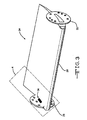
- Figure 3 is a perspective view of a structure according to another embodiment of the invention.
- Figure 4 is a magnified view of a portion of Figure 3 .
- the exemplary embodiment of the invention is a tape 10 that can be used to detect cracks in a structure to which it is attached.
- the tape 10 and/or other embodiments of the invention may be applied in different operating environments and for different purposes.
- the exemplary tape 10 includes a plurality of structural fiber, such as fibers 12,12a, 12b, 12c.
- Each structure fiber 12, 12a, 12b, 12c can be a solid, elongate member with an appreciable length.
- the fibers 12, 12a, 12b, 12c can be of different lengths.
- at least some of the fibers 12, 12a, 12b, 12c are boron fibers.
- alternative embodiments of the invention may include fibers formed from different materials.
- the multiple fibers 12, 12a, 12b, 12c of the tape 10 can also be fabricated from different materials relative to one another.
- the fibers 12, 12a, 12b, 12c can be fabricated using different manufacturing processes, such as being spun, drawn, or woven. Some or all of the fibers 12,12a, 12b, 12c can be flexible or rigid. One or more of the fibers 12,12a, 12b, 12c can each be a single filament or can be a strand formed from a plurality of filaments interwoven with one another. Alternative embodiments of the invention can include a tape having a combination of single filament fibers and strand fibers.
- the tape 10 also includes an electrically-insulating binder 14 at least partially encapsulating the plurality of structural fibers 12, 12a, 12b, 12c.
- the fibers 12, 12a, 12b, 12c can be substantially embedded in the binder 14, with only axially ends protruding as shown in Figure 1 .
- the tape 10 can be formed such that the fibers 12, 2a, 12b, 12c protrude out of a top surface 16 of binder 14 or a bottom surface 18 (referenced only in Figure 2 ).
- the tape 10 can be formed such that a "middle" portion of one or more of the fibers 12, 12a, 12b, 12c is exposed out of the binder 14.
- the portions of the fibers 12,12a, 12b, 12c within a box 20 shown in Figure 1 can be exposed through the top surface 16 and covered by the bottom surface 18 shown in Figure 2 .
- the binder 14 can any material appropriate in view of the operating environment.
- the binder 14 can at least partially include phthalonitrile.
- the tape 10 also includes quantities of electrically conductive particles 22.
- Each quantity of electrically conductive particles 22 can be connected with one of the plurality of structural fibers 12a, 12c.
- the electrically conductive particles 22 can be various materials in particle form, with the particles ranging in size.
- carbon nanotubes can be the electrically conductive particles 22.
- the electrically conducting particles can be carbon (graphite), silver, gold, copper, platinum or even finely particulate alloy materials.
- the electrically conductive particles 22 can be partially or fully embedded in the fibers 12a, 12c, or can be affixed to the outer surface of the fibers 12a, 12c. An amount of electrically conductive particles 22 can be connected with each fiber 12a, 12c until the conductivity across the respective fiber 12a, 12c reaches a suitable level.
- the fibers 12a, 12c themselves can be non-conductive or relatively poor conductors.
- the fibers 12a, 12c can be different from the electrically conductive particles 22 in at least one material property, such as conductivity or strength.
- the conductivity of copper may be desired so copper particles can be incorporated while the compressive properties of boron is desired so boron fibers are incorporated.
- the fibers 12a, 12c are larger than the electrically conductive particles 22.
- Figure 1 shows the fibers 12a and 12c each connected with a quantity of electrically conductive particles 22 and extending parallel to one another
- the fibers 12a, 12c could be oriented differently in alternative embodiments of the invention.
- the fibers 12a, 12c could be spokes of a hub and spoke pattern.
- less than all of the structural fibers 12, 12a, 12b, 12c are connected with at least one of the quantities of electrically conductive particles 22 in the exemplary embodiment of the invention.
- all of the fibers 12, 12a, 12b, 12c can be connected with at least one of the quantities of electrically conductive particles 22.
- a vane assembly 24 for a vanebox can include a vane 26 shaped like an airfoil as well as first and second mounting end caps 28, 30.
- a vanebox is a structure that can direct a stream of air for propelling or positioning the aircraft, such as in short and/or vertical take-offs and landings, It is noted that the present invention is not limited to vaneboxes and that alternative embodiments of the invention can be practiced with structures used for other purposes.
- the vane 26 and the end caps 28, 30 can be formed from any individual material or a composite of materials,
- the vane 30 can include a structural foam core with a composite spar.
- the core and spar can be overlaid with layers of carbon fiber and resin as a skin.
- the skin of the vane 36 could be the tape 10 shown in Figures 1 and 2 or a variation of the tape 10.
- Figure 4 is a magnified portion of end cap 28.
- the end cap 28 defines a body 32.
- a first parcel of tape 10 can be applied over a portion of the body 32 that is expected to experience relatively high loading during operation.
- the tape 10 can be applied to the body 32 with nanoglue or any other desired adhesive.
- the tape 10 can include a plurality of electrically conductive lines 12, 12a, 12b, 12c at least partially spaced from one another, an electrically-insulating binder 14 at least partially encapsulating the plurality of structural fibers 12, 12a, 12b, 12c. and quantities of carbon nanotubes 22, each quantity of carbon nanotubes 22 connected with one of the plurality of structural fibers 12,12a, 12b, 12c. All of the structural fibers of the tape 10 in Figure 4 can be connected with a quantity of carbon nanotubes 22.
- a second parcel of tape 10a can be layered transversely over the first parcel of tape 10.
- the tape 10a can be partially applied to the body 32 and partially applied to the first parcel of tape 10 with nanoglue or any other desired adhesive.
- the tape 10a can include a plurality of electrically conductive lines 12d, 12e, 12f, 12g, 12h at least partially spaced from one another, an electrically-insulating binder 14a at least partially encapsulating the plurality of structural fibers 12d, 12e, 12f, 12g, 12h and quantities of carbon nanotubes 22, each quantity of carbon nanotubes 22 connected with one of the plurality of structural fibers 12d, 12e, 12f, 12g, 12h. All of the structural fibers of the tape 10a in Figure 4 can be connected with a quantity of carbon nanotubes 22.
- the tape parcels 14, 10a can be formed such that middle portions of the fibers 12 - 12h are exposed on one side.
- the exposed middle portions of the fibers 12 - 12h can contact one another and be operable to communicate electricity between one another.
- Figure 4 shows at least one permissive difference from Figure 1 in that the respective ends of the fibers 12 - 12h do not extend out of the respective binders 14, 14a.
- the parcels of tape 10, 10a can be applied on the body 32 such that the electrically conductive fibers or lines 12 - 12c of the first parcel of tape 10 are nonparallel to the electrically conductive fibers or lines 12d - 12h of a second parcel of tape 10a.
- the lines 12 - 12h are made electrically conductive or have enhanced conductivity through the carbon nanotubes 22 or some other kind of electrically conductive particles.
- the electrically conductive lines 12d - 12h therefore can form an electrical grid 34.
- Electrical leads 36, 38, 40, 42 can be connected to the grid 34 at various locations.
- a controller assembly 44 can direct current through the grid 34 through connections with the various electrical leads 36, 38, 40, 42 and monitor voltage levels at the each of the electrical leads 36, 38, 40,42. Only four electrical leads 36, 38, 40, 42 are shown, however, the controller 44 can engage every intersection point of the grid 34 along the outer perimeter of the grid 34 in various embodiments of the invention.
- the controller 44 can be operable to detect the location of the crack within the grid 34 based on changes in voltage at the various monitored points along the perimeter of the grid 34.
- the first and second parcels of tape 10 and 10a individually and collectively increase the robustness of the body 32.
- the fibers 12 - 12h are bonded to the body 32 and thereby enhance the structural properties of the body 32.
- the material or combination of materials chosen to make the fibers 12 - 12h can be selected to increase the tensile strength of the body 32.
- these chosen fibers 12 - 12h can cause the tensile strength of the combined structure (body 32 and fibers 12 - 12h) to be greater than the tensile strength of the body 32 alone.
- the material or combination of materials chosen to make the fibers 12 - 12h can be selected to increase the compressive strength of the body 32.
- these chosen fibers 12 - 12h can cause the compressive strength of the combined structure (body 32 and fibers 12 - 12h) to be greater than the compressive strength of the body 32 alone.
- the fibers 12 - 12h can be selected such that the likelihood of cracking in the body 32 is reduced because of their attachment to the body 32.
Landscapes
- Physics & Mathematics (AREA)
- Engineering & Computer Science (AREA)
- Aviation & Aerospace Engineering (AREA)
- General Physics & Mathematics (AREA)
- Chemical & Material Sciences (AREA)
- Dispersion Chemistry (AREA)
- Spectroscopy & Molecular Physics (AREA)
- Laminated Bodies (AREA)
- Investigating Or Analyzing Materials By The Use Of Electric Means (AREA)
Abstract
Description
- The invention relates to an apparatus and method operable to detect the presence of cracks in a structure.
-
U.S. Patent No. 4,484,132 shows a metal structure (P) covered with an insulating substrate (21) inFigure 4 . Electrically-conducting lines (22) are formed across the substrate (21). The lines (22) are a combination of electrically conductive particles suspended in a flowable material. The lines (22) are applied with a pen or syringe, shown in Figure 10. After being applied to the substrate (21), the lines (22) cure and dry out A second insulating layer (23) is applied over the lines (22). When the structure (P) cracks, the substrate (21) and lines (22) adjacent to the crack will also fracture, resulting in a change in voltage across at least one of the lines (22). - In summary, the invention is a tape that can be used to detect cracks in a structure to which it is attached. The tape includes a plurality of structural fibers. The tape also includes an electrically-insulating binder at least partially encapsulating the plurality of structural fibers. The tape also includes quantities of electrically conductive particles, each quantity of electrically conductive particles connected with one of the plurality of structural fibers.
- Advantages of the present invention will be readily appreciated as the same becomes better understood by reference to the following detailed description of an exemplary embodiment when considered in connection with the accompanying drawings wherein:
-
Figure 1 is a top view of a parcel of tape according to an exemplary embodiment of the invention; -
Figure 2 is a right-hand view of the parcel oftape shown inFigure 1 ; -
Figure 3 is a perspective view of a structure according to another embodiment of the invention; and -
Figure 4 is a magnified view of a portion ofFigure 3 . - Referring now to
Figures 1 and 2 , the exemplary embodiment of the invention is atape 10 that can be used to detect cracks in a structure to which it is attached. Thetape 10 and/or other embodiments of the invention may be applied in different operating environments and for different purposes. Theexemplary tape 10 includes a plurality of structural fiber, such asfibers - Each
structure fiber fibers fibers multiple fibers tape 10 can also be fabricated from different materials relative to one another. - The
fibers fibers fibers - The
tape 10 also includes an electrically-insulatingbinder 14 at least partially encapsulating the plurality ofstructural fibers fibers binder 14, with only axially ends protruding as shown inFigure 1 . Alternatively, thetape 10 can be formed such that thefibers top surface 16 ofbinder 14 or a bottom surface 18 (referenced only inFigure 2 ). Also, thetape 10 can be formed such that a "middle" portion of one or more of thefibers binder 14. For example, the portions of thefibers box 20 shown inFigure 1 can be exposed through thetop surface 16 and covered by thebottom surface 18 shown inFigure 2 . Thebinder 14 can any material appropriate in view of the operating environment. In the exemplary embodiment of the invention, thebinder 14 can at least partially include phthalonitrile. - The
tape 10 also includes quantities of electricallyconductive particles 22. Each quantity of electricallyconductive particles 22 can be connected with one of the plurality ofstructural fibers conductive particles 22 can be various materials in particle form, with the particles ranging in size. In the exemplary embodiment of the invention, carbon nanotubes can be the electricallyconductive particles 22. In alternative embodiments of the invention, the electrically conducting particles can be carbon (graphite), silver, gold, copper, platinum or even finely particulate alloy materials. - The electrically
conductive particles 22 can be partially or fully embedded in thefibers fibers conductive particles 22 can be connected with eachfiber respective fiber fibers fibers conductive particles 22 in at least one material property, such as conductivity or strength. For example, in one embodiment of the invention, the conductivity of copper may be desired so copper particles can be incorporated while the compressive properties of boron is desired so boron fibers are incorporated. Thefibers conductive particles 22. -
Figure 1 shows thefibers conductive particles 22 and extending parallel to one another, Thefibers fibers structural fibers conductive particles 22 in the exemplary embodiment of the invention. However, in alternative embodiments of the invention, all of thefibers conductive particles 22. -
Figures 3 and4 show an application of the exemplary embodiment of the invention. InFigure 3 , avane assembly 24 for a vanebox can include avane 26 shaped like an airfoil as well as first and secondmounting end caps - The
vane 26 and theend caps vane 30 can include a structural foam core with a composite spar. The core and spar can be overlaid with layers of carbon fiber and resin as a skin. In alternative embodiments of the invention, the skin of thevane 36 could be thetape 10 shown inFigures 1 and 2 or a variation of thetape 10. -
Figure 4 is a magnified portion ofend cap 28. Theend cap 28 defines abody 32. A first parcel oftape 10 can be applied over a portion of thebody 32 that is expected to experience relatively high loading during operation. Thetape 10 can be applied to thebody 32 with nanoglue or any other desired adhesive. Thetape 10 can include a plurality of electricallyconductive lines binder 14 at least partially encapsulating the plurality ofstructural fibers carbon nanotubes 22, each quantity ofcarbon nanotubes 22 connected with one of the plurality ofstructural fibers tape 10 inFigure 4 can be connected with a quantity ofcarbon nanotubes 22. - A second parcel of
tape 10a can be layered transversely over the first parcel oftape 10. Thetape 10a can be partially applied to thebody 32 and partially applied to the first parcel oftape 10 with nanoglue or any other desired adhesive. Thetape 10a can include a plurality of electricallyconductive lines binder 14a at least partially encapsulating the plurality ofstructural fibers carbon nanotubes 22, each quantity ofcarbon nanotubes 22 connected with one of the plurality ofstructural fibers tape 10a inFigure 4 can be connected with a quantity ofcarbon nanotubes 22. - As described above with respect to
Figure 1 , thetape parcels tape parcels Figure 4 shows at least one permissive difference fromFigure 1 in that the respective ends of the fibers 12 - 12h do not extend out of therespective binders - As shown in
Figure 4 , the parcels oftape body 32 such that the electrically conductive fibers or lines 12 - 12c of the first parcel oftape 10 are nonparallel to the electrically conductive fibers orlines 12d - 12h of a second parcel oftape 10a. The lines 12 - 12h are made electrically conductive or have enhanced conductivity through thecarbon nanotubes 22 or some other kind of electrically conductive particles. The electricallyconductive lines 12d - 12h therefore can form anelectrical grid 34. - Electrical leads 36, 38, 40, 42 (shown schematically) can be connected to the
grid 34 at various locations. Acontroller assembly 44 can direct current through thegrid 34 through connections with the variouselectrical leads electrical leads controller 44 can engage every intersection point of thegrid 34 along the outer perimeter of thegrid 34 in various embodiments of the invention. - If the
body 32 cracks, at least one of the parcels oftape grid 34 along the outer perimeter of thegrid 34 will change. Thecontroller 44 can be operable to detect the location of the crack within thegrid 34 based on changes in voltage at the various monitored points along the perimeter of thegrid 34. One methodology for performing this analysis is set forth inU.S. Patent. No. 7,167,009 , which is hereby incorporated by reference. - The first and second parcels of
tape body 32. In other words, the fibers 12 - 12h are bonded to thebody 32 and thereby enhance the structural properties of thebody 32. The material or combination of materials chosen to make the fibers 12 - 12h can be selected to increase the tensile strength of thebody 32. When bonded to thebody 32 at a location on thebody 32 subject to tensile loads, these chosen fibers 12 - 12h can cause the tensile strength of the combined structure (body 32 and fibers 12 - 12h) to be greater than the tensile strength of thebody 32 alone. Alternatively, the material or combination of materials chosen to make the fibers 12 - 12h can be selected to increase the compressive strength of thebody 32. When bonded to thebody 32 at a location on thebody 32 Subject to compressive loads, these chosen fibers 12 - 12h can cause the compressive strength of the combined structure (body 32 and fibers 12 - 12h) to be greater than the compressive strength of thebody 32 alone. Generally, the fibers 12 - 12h can be selected such that the likelihood of cracking in thebody 32 is reduced because of their attachment to thebody 32. - While the invention has been described with reference to an exemplary embodiment, it will be understood by those skilled in the art that various changes may be made and equivalents may be substituted for elements thereof without departing from the scope of the invention. In addition, many modifications may be made to adapt a particular situation or material to the teachings of the invention without departing from the essential scope thereof. Therefore, it is intended that the invention not be limited to the particular embodiment disclosed as the best mode contemplated for carrying out this invention, but that the invention will include all embodiments falling within the scope of the appended claims.
Claims (15)
- A tape comprising:a plurality of structural fibers;an etectrically-insulating binder at least partially encapsulating said plurality of structural fibers; andquantities of electrically conductive particles, each quantity of electrically conductive particles connected with at least one of said plurality of structural fibers.
- The tape of claim 1 wherein less than all of said plurality of structural fibers are connected with at least one of said quantities of electrically conductive particles.
- The tape of claim 1 or 2, wherein said quantities of electrically conductive particles include a first quantity of electrically conductive particles connected to a first of said plurality of structural fibers and a second quantity of electrically conductive particles connected to a second of said plurality of structural fibers, wherein said first and second structural fibers are parallel to one another.
- The tape of claims 1, to 3, wherein said plurality of structural fibers are electrically non-conductive; and/or wherein each of said quantities of electrically conductive particles are further defined as carbon nanotubes; and/or wherein the tape further comprises first and second electrical leads affixed to at least one of said plurality of fibers being connected with one of said quantities of electrically conductive particles, said first and second leads spaced from one another and operable to communicate a current through said quantity of electrically conductive particles; and/or wherein said plurality of structural fibers are further defined as boron fibers; and/or wherein said binder is further define as at least partially including phthalonitrile; and/or wherein the tape further comprises an adhesive layer of nanoglue.
- A method comprising the steps of:applying a tape having a plurality of electrically conductive lines at least partially spaced from one another on a structure for detecting cracks in the structure; andincreasing the robustness of the structure with the crack-detecting tape.
- The method of claim 5, wherein said increasing step is further defined as:increasing the tensile strength of the structure at a location on the structure subject to tensile loads with the tape.
- The method of claim 5, wherein said increasing step is further defined as:increasing the compressive strength of the structure at a location on the structure subject to compressive loads with the tape.
- The method of claim 5, wherein said increasing step is further defined as:preventing cracking at a location on the structure with the tape.
- The method of claim 5, wherein said applying step further comprises the step of:bonding the tape to the structure with nanoglue.
- The method of claim 5, wherein said applying step further comprises the step of:layering a plurality of parcels of the tape on the structure, wherein the electrically conductive lines of a first parcel of the tape are nonparallel to the electrically conductive lines of a second parcel of tape.
- An apparatus comprising:a body;a first parcel of tape covering a portion of said body subjected to loading, said tape having a plurality of structural fibers, an electrically-insulating binder at least partially encapsulating said plurality of structural fibers, and quantities of carbon nanotubes, each quantity of carbon nanotubes connected with one of said plurality of structural fibers; andfirst and second electrical leads connected to at least one of said plurality of fibers connected with one of said quantities of carbon nanotubes, said first and second leads spaced from one another and operable to communicate a current through said quantity of carbon nanotubes,
- The apparatus of claim 11, further comprising:a second parcel of tape at least partially overlaying said first parcel of tape, said second parcel of tape having a plurality of structural fibers, an electrically-insulating binder at least partially encapsulating said plurality of structural fibers, and quantities of carbon nanotubes, each quantity of carbon nanotubes connected with one of said plurality of structural fibers; andthird and fourth electrical leads connected to at least one of said plurality of fibers connected with one of said quantities of carbon nanotubes of said second parcel of tape, said third and fourth leads spaced from one another and operable to communicate a current through said quantity of carbon nanotubes of said second parcel of tape.
- The apparatus of claim 12, wherein at least a portion of said plurality of structural fibers connected with said carbon nanotubes of said first parcel of tape extend nonparallel to and are in contact with at least a portion of said plurality of structural fibers connected with said carbon nanotubes of said second parcel of tape, wherein a grid of structure fibers connected with said carbon nanotubes is formed by the cooperation between said first and second parcels of tape,
- The apparatus of claim 13, wherein said first and second parcels of tape are further defined as being at least partially bonded to said body with nanoglue.
- The apparatus of claim 11, wherein said body is metallic or composite.
Applications Claiming Priority (1)
| Application Number | Priority Date | Filing Date | Title |
|---|---|---|---|
| US12/252,403 US8778487B2 (en) | 2008-10-16 | 2008-10-16 | Tape |
Publications (3)
| Publication Number | Publication Date |
|---|---|
| EP2177900A2 true EP2177900A2 (en) | 2010-04-21 |
| EP2177900A3 EP2177900A3 (en) | 2010-07-14 |
| EP2177900B1 EP2177900B1 (en) | 2012-05-02 |
Family
ID=41571563
Family Applications (1)
| Application Number | Title | Priority Date | Filing Date |
|---|---|---|---|
| EP20090252425 Active EP2177900B1 (en) | 2008-10-16 | 2009-10-15 | Conductive tape for crack detection |
Country Status (3)
| Country | Link |
|---|---|
| US (1) | US8778487B2 (en) |
| EP (1) | EP2177900B1 (en) |
| AT (1) | ATE556314T1 (en) |
Cited By (2)
| Publication number | Priority date | Publication date | Assignee | Title |
|---|---|---|---|---|
| CN102677202A (en) * | 2011-03-11 | 2012-09-19 | 艾普特佩克股份有限公司 | Fiber, fiber aggregate, and adhesive having the fiber aggregate |
| EP2469028B1 (en) * | 2010-12-27 | 2016-12-14 | Rolls-Royce Corporation | Airfoil for a turbomachine comprising a metal foam core |
Families Citing this family (5)
| Publication number | Priority date | Publication date | Assignee | Title |
|---|---|---|---|---|
| US20100098896A1 (en) * | 2008-10-16 | 2010-04-22 | Edward Claude Rice | Patch |
| DE102013014822A1 (en) * | 2013-09-10 | 2015-03-12 | Airbus Defence and Space GmbH | Structure monitoring system for a material and manufacturing process |
| FR3073354B1 (en) | 2017-11-06 | 2019-10-18 | Safran | COMPOSITE COMPONENT WITH INTEGRATED INSTRUMENTATION ELECTRONIC CIRCUIT AND METHOD FOR MANUFACTURING THE SAME |
| KR102578194B1 (en) * | 2018-06-20 | 2023-09-13 | 현대자동차주식회사 | Apparatus and method for detecting damage of vehicle |
| GB2621191A (en) * | 2022-08-05 | 2024-02-07 | Bae Systems Plc | Functionalized tape for the manufacturing of fibre-reinforced composite parts |
Citations (1)
| Publication number | Priority date | Publication date | Assignee | Title |
|---|---|---|---|---|
| US4484132A (en) | 1981-03-09 | 1984-11-20 | Crites Nelson A | Crack detecting system |
Family Cites Families (42)
| Publication number | Priority date | Publication date | Assignee | Title |
|---|---|---|---|---|
| US591822A (en) | 1897-10-19 | curtis | ||
| US3509942A (en) | 1966-08-15 | 1970-05-05 | John E Lindberg | System for detecting structural failure |
| GB1328167A (en) | 1971-06-18 | 1973-08-30 | Rolls Royce | Rotor blade for a gas turbine engine |
| US3979949A (en) | 1975-06-30 | 1976-09-14 | The Boeing Company | Fatigue damage indicator |
| US4503710A (en) | 1983-06-08 | 1985-03-12 | Conoco Inc. | Crack detection by electrical resistance |
| US4591511A (en) | 1984-07-30 | 1986-05-27 | The United States Of America As Represented By The Secretary Of The Navy | Adhesive repair patch |
| DE3429250C1 (en) | 1984-08-08 | 1986-03-27 | Texas Instruments Deutschland Gmbh, 8050 Freising | Sensor responsive to the action of a force |
| US4759812A (en) | 1985-07-11 | 1988-07-26 | Miller Robert W | Method and apparatus for effecting field repairs in stress carrying structures |
| GB2204888A (en) * | 1987-05-18 | 1988-11-23 | Textilver Sa | Fibre reinforced matrix |
| GB2243412B (en) | 1990-03-30 | 1994-11-23 | United Technologies Corp | Aircraft engine propulsor blade deicing |
| US5065630A (en) | 1990-06-12 | 1991-11-19 | Grumman Aerospace Corporation | Integrated system for aircraft crack detection |
| DE69129944D1 (en) | 1990-11-23 | 1998-09-10 | Akro Fireguard Prod Inc | FIRE-RESISTANT REPAIR PATCH AND METHOD FOR THE PRODUCTION THEREOF |
| US5379644A (en) | 1991-08-15 | 1995-01-10 | Shimizu Costruction Co., Ltd. | Strain or stress gauge and method for detecting strain or stress of structure using the same, and plastic composite material for foreknowing progress of breakdown of structure and method using the same |
| US5698977A (en) | 1993-10-12 | 1997-12-16 | The United States Of America As Represented By The Administrator Of The National Aeronautics And Space Administration | Eddy current method for fatigue testing |
| US20030088980A1 (en) | 1993-11-01 | 2003-05-15 | Arnold James E. | Method for correcting defects in a workpiece |
| GB9409553D0 (en) | 1994-04-28 | 1994-06-29 | British Aerospace | Crack detection system |
| JP3052047B2 (en) | 1994-09-07 | 2000-06-12 | 本田技研工業株式会社 | Method of measuring stress of ferromagnetic metal body, method of measuring stress distribution in sheet-like sensor, and sheet-like sensor for measuring stress distribution |
| US5518565A (en) | 1994-09-14 | 1996-05-21 | Northrop Grumman Corporation | Method of repairing a hole in a sheet member |
| US5958166A (en) | 1996-12-31 | 1999-09-28 | Mcdonnell Douglas Corporation | Method for repairing high temperature composite structures |
| FR2763882B1 (en) | 1997-05-29 | 1999-08-20 | Aerospatiale | ON-SITE REPAIR TOOLS OF A COMPOSITE STRUCTURE HAVING A DAMAGED AREA AND CORRESPONDING METHOD |
| FR2768994B1 (en) | 1997-09-30 | 2001-12-21 | Deutsch Zentr Luft & Raumfahrt | PROFILE |
| FR2777496B1 (en) | 1998-04-17 | 2000-08-04 | Sunkiss Aeronautique | PROCESS FOR OBTAINING, REPAIRING OR RECONSTRUCTING AN OBJECT WITH A PART OR COMPOSITE MATERIAL |
| JP2001082102A (en) | 1999-09-10 | 2001-03-27 | Natl Aerospace Lab | Rotary blade having automatic shape adjusting function |
| CA2442273A1 (en) | 2001-03-26 | 2002-10-03 | Eikos, Inc. | Carbon nanotubes in structures and repair compositions |
| US6759352B2 (en) | 2001-07-05 | 2004-07-06 | Sony Corporation | Composite carbon fiber material and method of making same |
| US6656299B1 (en) | 2001-12-19 | 2003-12-02 | Lockheed Martin Corporation | Method and apparatus for structural repair |
| US7167009B2 (en) | 2002-04-16 | 2007-01-23 | Mide Technology Corporation | Method and apparatus for determining electrical properties of structures |
| DE10223985A1 (en) | 2002-05-29 | 2003-12-18 | Siemens Ag | Arrangement from a component and a control device, method for producing the arrangement and use of the arrangement |
| ITTO20020699A1 (en) | 2002-08-06 | 2004-02-07 | Fiatavio Spa | VANE FOR THE STATOR OF A VARIABLE GEOMETRY TURBINE, |
| US7431981B2 (en) * | 2002-11-04 | 2008-10-07 | The Boeing Company | Polymer composite structure reinforced with shape memory alloy and method of manufacturing same |
| US7216428B2 (en) | 2003-03-03 | 2007-05-15 | United Technologies Corporation | Method for turbine element repairing |
| US7310949B2 (en) | 2003-11-07 | 2007-12-25 | General Electric Company | Method and apparatus for arresting a crack within a body |
| US7938923B2 (en) | 2004-06-04 | 2011-05-10 | Cornerstone Research Group, Inc. | Method of making and using shape memory polymer composite patches |
| GB0428368D0 (en) | 2004-12-24 | 2005-02-02 | Rolls Royce Plc | A composite blade |
| US7278830B2 (en) | 2005-05-18 | 2007-10-09 | Allison Advanced Development Company, Inc. | Composite filled gas turbine engine blade with gas film damper |
| US7225681B2 (en) | 2005-06-06 | 2007-06-05 | Texas Instruments Incorporated | Statistical method for identifying microcracks in insulators |
| GB0519502D0 (en) | 2005-09-24 | 2005-11-02 | Rolls Royce Plc | Vane assembly |
| US7419556B2 (en) | 2005-10-11 | 2008-09-02 | United Technologies Corporation | Method of repair for inlet caps of turbine engines |
| US20070079507A1 (en) | 2005-10-12 | 2007-04-12 | Kenny Cheng | Blade shroud repair |
| US7398698B2 (en) | 2005-11-03 | 2008-07-15 | The Boeing Company | Smart repair patch and associated method |
| US8148276B2 (en) * | 2005-11-28 | 2012-04-03 | University Of Hawaii | Three-dimensionally reinforced multifunctional nanocomposites |
| US7653994B2 (en) | 2006-03-22 | 2010-02-02 | General Electric Company | Repair of HPT shrouds with sintered preforms |
-
2008
- 2008-10-16 US US12/252,403 patent/US8778487B2/en active Active
-
2009
- 2009-10-15 EP EP20090252425 patent/EP2177900B1/en active Active
- 2009-10-15 AT AT09252425T patent/ATE556314T1/en active
Patent Citations (1)
| Publication number | Priority date | Publication date | Assignee | Title |
|---|---|---|---|---|
| US4484132A (en) | 1981-03-09 | 1984-11-20 | Crites Nelson A | Crack detecting system |
Cited By (2)
| Publication number | Priority date | Publication date | Assignee | Title |
|---|---|---|---|---|
| EP2469028B1 (en) * | 2010-12-27 | 2016-12-14 | Rolls-Royce Corporation | Airfoil for a turbomachine comprising a metal foam core |
| CN102677202A (en) * | 2011-03-11 | 2012-09-19 | 艾普特佩克股份有限公司 | Fiber, fiber aggregate, and adhesive having the fiber aggregate |
Also Published As
| Publication number | Publication date |
|---|---|
| US20100096183A1 (en) | 2010-04-22 |
| EP2177900B1 (en) | 2012-05-02 |
| ATE556314T1 (en) | 2012-05-15 |
| EP2177900A3 (en) | 2010-07-14 |
| US8778487B2 (en) | 2014-07-15 |
Similar Documents
| Publication | Publication Date | Title |
|---|---|---|
| EP2177900A2 (en) | Conductive tape for crack detection | |
| US8937254B2 (en) | Apparatus and method for an aircraft conductor sandwich assembly embedded to an aircraft structure | |
| CN108700041B (en) | Wind turbine blade and potential equalising system | |
| EP1826402B1 (en) | Lightning conductor system for wind generator blades comprising carbon fibre laminates | |
| EP2390498B1 (en) | Wind turbine blade with coating for lightning protection and method for manufacturing the wind turbine blade | |
| US20180156202A1 (en) | Spar cap assembly for a wind turbine rotor blade | |
| JP2010518588A (en) | Electrical conductor | |
| US10167550B2 (en) | Multi-functional composite structures | |
| EP2650210A1 (en) | Lightning protection sheet with patterned discriminator | |
| CN110608140B (en) | Stepped conductivity interface | |
| WO2004053464A1 (en) | Embedded nanotube array sensor and method of making a nanotube polymer composite | |
| EP3617280A1 (en) | Integrated surface protection system, composite structure, and method for protecting the same | |
| EP1826119A3 (en) | Composite ice protection heater and method of producing same | |
| CN103662083A (en) | Method for producing an aircraft structure component having an outer skin provided with electric conductor elements | |
| US9130363B2 (en) | Lightning strike protection means and fiber composite component | |
| EP3334247B1 (en) | Carbon nanotube yarn heater | |
| CN113167219A (en) | Spar structure with integrated lower conductor element for lightning protection system | |
| EP1450377A2 (en) | Structurally integrated wire and associated fabrication method | |
| US20220018328A1 (en) | Rotor blade of a wind turbine, comprising an insulator layer and a protective layer | |
| CN107521653A (en) | Thunderbolt for compound aircaft configuration disperses | |
| CN101094986A (en) | Lightning conductor system for wind generator blades comprising carbon fibre laminates | |
| CN120283109A (en) | Improved electrical conductivity of wind turbine blade components | |
| JP2006153471A (en) | Pressure sensor | |
| Cochrane et al. | Smart nanotextiles for transportation | |
| US9585294B2 (en) | Arrangement for electromagnetic screening |
Legal Events
| Date | Code | Title | Description |
|---|---|---|---|
| PUAI | Public reference made under article 153(3) epc to a published international application that has entered the european phase |
Free format text: ORIGINAL CODE: 0009012 |
|
| AK | Designated contracting states |
Kind code of ref document: A2 Designated state(s): AT BE BG CH CY CZ DE DK EE ES FI FR GB GR HR HU IE IS IT LI LT LU LV MC MK MT NL NO PL PT RO SE SI SK SM TR |
|
| AX | Request for extension of the european patent |
Extension state: AL BA RS |
|
| 17P | Request for examination filed |
Effective date: 20100414 |
|
| PUAL | Search report despatched |
Free format text: ORIGINAL CODE: 0009013 |
|
| AK | Designated contracting states |
Kind code of ref document: A3 Designated state(s): AT BE BG CH CY CZ DE DK EE ES FI FR GB GR HR HU IE IS IT LI LT LU LV MC MK MT NL NO PL PT RO SE SI SK SM TR |
|
| AX | Request for extension of the european patent |
Extension state: AL BA RS |
|
| GRAP | Despatch of communication of intention to grant a patent |
Free format text: ORIGINAL CODE: EPIDOSNIGR1 |
|
| RIC1 | Information provided on ipc code assigned before grant |
Ipc: G01M 5/00 20060101ALI20110914BHEP Ipc: H01B 1/24 20060101ALI20110914BHEP Ipc: H01B 1/22 20060101ALI20110914BHEP Ipc: G01N 27/20 20060101AFI20110914BHEP |
|
| GRAS | Grant fee paid |
Free format text: ORIGINAL CODE: EPIDOSNIGR3 |
|
| GRAA | (expected) grant |
Free format text: ORIGINAL CODE: 0009210 |
|
| AK | Designated contracting states |
Kind code of ref document: B1 Designated state(s): AT BE BG CH CY CZ DE DK EE ES FI FR GB GR HR HU IE IS IT LI LT LU LV MC MK MT NL NO PL PT RO SE SI SK SM TR |
|
| REG | Reference to a national code |
Ref country code: GB Ref legal event code: FG4D |
|
| REG | Reference to a national code |
Ref country code: AT Ref legal event code: REF Ref document number: 556314 Country of ref document: AT Kind code of ref document: T Effective date: 20120515 Ref country code: CH Ref legal event code: EP |
|
| REG | Reference to a national code |
Ref country code: IE Ref legal event code: FG4D |
|
| REG | Reference to a national code |
Ref country code: DE Ref legal event code: R096 Ref document number: 602009006743 Country of ref document: DE Effective date: 20120705 |
|
| REG | Reference to a national code |
Ref country code: NL Ref legal event code: VDEP Effective date: 20120502 |
|
| REG | Reference to a national code |
Ref country code: LT Ref legal event code: MG4D Effective date: 20120502 |
|
| PG25 | Lapsed in a contracting state [announced via postgrant information from national office to epo] |
Ref country code: FI Free format text: LAPSE BECAUSE OF FAILURE TO SUBMIT A TRANSLATION OF THE DESCRIPTION OR TO PAY THE FEE WITHIN THE PRESCRIBED TIME-LIMIT Effective date: 20120502 Ref country code: LT Free format text: LAPSE BECAUSE OF FAILURE TO SUBMIT A TRANSLATION OF THE DESCRIPTION OR TO PAY THE FEE WITHIN THE PRESCRIBED TIME-LIMIT Effective date: 20120502 Ref country code: CY Free format text: LAPSE BECAUSE OF FAILURE TO SUBMIT A TRANSLATION OF THE DESCRIPTION OR TO PAY THE FEE WITHIN THE PRESCRIBED TIME-LIMIT Effective date: 20120502 Ref country code: PL Free format text: LAPSE BECAUSE OF FAILURE TO SUBMIT A TRANSLATION OF THE DESCRIPTION OR TO PAY THE FEE WITHIN THE PRESCRIBED TIME-LIMIT Effective date: 20120502 Ref country code: NO Free format text: LAPSE BECAUSE OF FAILURE TO SUBMIT A TRANSLATION OF THE DESCRIPTION OR TO PAY THE FEE WITHIN THE PRESCRIBED TIME-LIMIT Effective date: 20120802 Ref country code: SE Free format text: LAPSE BECAUSE OF FAILURE TO SUBMIT A TRANSLATION OF THE DESCRIPTION OR TO PAY THE FEE WITHIN THE PRESCRIBED TIME-LIMIT Effective date: 20120502 Ref country code: IS Free format text: LAPSE BECAUSE OF FAILURE TO SUBMIT A TRANSLATION OF THE DESCRIPTION OR TO PAY THE FEE WITHIN THE PRESCRIBED TIME-LIMIT Effective date: 20120902 |
|
| REG | Reference to a national code |
Ref country code: AT Ref legal event code: MK05 Ref document number: 556314 Country of ref document: AT Kind code of ref document: T Effective date: 20120502 |
|
| PG25 | Lapsed in a contracting state [announced via postgrant information from national office to epo] |
Ref country code: GR Free format text: LAPSE BECAUSE OF FAILURE TO SUBMIT A TRANSLATION OF THE DESCRIPTION OR TO PAY THE FEE WITHIN THE PRESCRIBED TIME-LIMIT Effective date: 20120803 Ref country code: SI Free format text: LAPSE BECAUSE OF FAILURE TO SUBMIT A TRANSLATION OF THE DESCRIPTION OR TO PAY THE FEE WITHIN THE PRESCRIBED TIME-LIMIT Effective date: 20120502 Ref country code: PT Free format text: LAPSE BECAUSE OF FAILURE TO SUBMIT A TRANSLATION OF THE DESCRIPTION OR TO PAY THE FEE WITHIN THE PRESCRIBED TIME-LIMIT Effective date: 20120903 Ref country code: LV Free format text: LAPSE BECAUSE OF FAILURE TO SUBMIT A TRANSLATION OF THE DESCRIPTION OR TO PAY THE FEE WITHIN THE PRESCRIBED TIME-LIMIT Effective date: 20120502 Ref country code: HR Free format text: LAPSE BECAUSE OF FAILURE TO SUBMIT A TRANSLATION OF THE DESCRIPTION OR TO PAY THE FEE WITHIN THE PRESCRIBED TIME-LIMIT Effective date: 20120502 |
|
| PG25 | Lapsed in a contracting state [announced via postgrant information from national office to epo] |
Ref country code: BE Free format text: LAPSE BECAUSE OF FAILURE TO SUBMIT A TRANSLATION OF THE DESCRIPTION OR TO PAY THE FEE WITHIN THE PRESCRIBED TIME-LIMIT Effective date: 20120502 |
|
| PG25 | Lapsed in a contracting state [announced via postgrant information from national office to epo] |
Ref country code: NL Free format text: LAPSE BECAUSE OF FAILURE TO SUBMIT A TRANSLATION OF THE DESCRIPTION OR TO PAY THE FEE WITHIN THE PRESCRIBED TIME-LIMIT Effective date: 20120502 Ref country code: RO Free format text: LAPSE BECAUSE OF FAILURE TO SUBMIT A TRANSLATION OF THE DESCRIPTION OR TO PAY THE FEE WITHIN THE PRESCRIBED TIME-LIMIT Effective date: 20120502 Ref country code: AT Free format text: LAPSE BECAUSE OF FAILURE TO SUBMIT A TRANSLATION OF THE DESCRIPTION OR TO PAY THE FEE WITHIN THE PRESCRIBED TIME-LIMIT Effective date: 20120502 Ref country code: CZ Free format text: LAPSE BECAUSE OF FAILURE TO SUBMIT A TRANSLATION OF THE DESCRIPTION OR TO PAY THE FEE WITHIN THE PRESCRIBED TIME-LIMIT Effective date: 20120502 Ref country code: DK Free format text: LAPSE BECAUSE OF FAILURE TO SUBMIT A TRANSLATION OF THE DESCRIPTION OR TO PAY THE FEE WITHIN THE PRESCRIBED TIME-LIMIT Effective date: 20120502 Ref country code: EE Free format text: LAPSE BECAUSE OF FAILURE TO SUBMIT A TRANSLATION OF THE DESCRIPTION OR TO PAY THE FEE WITHIN THE PRESCRIBED TIME-LIMIT Effective date: 20120502 Ref country code: SK Free format text: LAPSE BECAUSE OF FAILURE TO SUBMIT A TRANSLATION OF THE DESCRIPTION OR TO PAY THE FEE WITHIN THE PRESCRIBED TIME-LIMIT Effective date: 20120502 |
|
| PG25 | Lapsed in a contracting state [announced via postgrant information from national office to epo] |
Ref country code: IT Free format text: LAPSE BECAUSE OF FAILURE TO SUBMIT A TRANSLATION OF THE DESCRIPTION OR TO PAY THE FEE WITHIN THE PRESCRIBED TIME-LIMIT Effective date: 20120502 |
|
| PLBE | No opposition filed within time limit |
Free format text: ORIGINAL CODE: 0009261 |
|
| STAA | Information on the status of an ep patent application or granted ep patent |
Free format text: STATUS: NO OPPOSITION FILED WITHIN TIME LIMIT |
|
| 26N | No opposition filed |
Effective date: 20130205 |
|
| PG25 | Lapsed in a contracting state [announced via postgrant information from national office to epo] |
Ref country code: ES Free format text: LAPSE BECAUSE OF FAILURE TO SUBMIT A TRANSLATION OF THE DESCRIPTION OR TO PAY THE FEE WITHIN THE PRESCRIBED TIME-LIMIT Effective date: 20120813 |
|
| REG | Reference to a national code |
Ref country code: DE Ref legal event code: R097 Ref document number: 602009006743 Country of ref document: DE Effective date: 20130205 |
|
| PG25 | Lapsed in a contracting state [announced via postgrant information from national office to epo] |
Ref country code: MC Free format text: LAPSE BECAUSE OF NON-PAYMENT OF DUE FEES Effective date: 20121031 |
|
| REG | Reference to a national code |
Ref country code: IE Ref legal event code: MM4A |
|
| PG25 | Lapsed in a contracting state [announced via postgrant information from national office to epo] |
Ref country code: IE Free format text: LAPSE BECAUSE OF NON-PAYMENT OF DUE FEES Effective date: 20121015 Ref country code: BG Free format text: LAPSE BECAUSE OF FAILURE TO SUBMIT A TRANSLATION OF THE DESCRIPTION OR TO PAY THE FEE WITHIN THE PRESCRIBED TIME-LIMIT Effective date: 20120802 |
|
| PG25 | Lapsed in a contracting state [announced via postgrant information from national office to epo] |
Ref country code: MT Free format text: LAPSE BECAUSE OF FAILURE TO SUBMIT A TRANSLATION OF THE DESCRIPTION OR TO PAY THE FEE WITHIN THE PRESCRIBED TIME-LIMIT Effective date: 20120502 |
|
| PGFP | Annual fee paid to national office [announced via postgrant information from national office to epo] |
Ref country code: GB Payment date: 20131021 Year of fee payment: 5 |
|
| PG25 | Lapsed in a contracting state [announced via postgrant information from national office to epo] |
Ref country code: TR Free format text: LAPSE BECAUSE OF FAILURE TO SUBMIT A TRANSLATION OF THE DESCRIPTION OR TO PAY THE FEE WITHIN THE PRESCRIBED TIME-LIMIT Effective date: 20120502 |
|
| PG25 | Lapsed in a contracting state [announced via postgrant information from national office to epo] |
Ref country code: SM Free format text: LAPSE BECAUSE OF FAILURE TO SUBMIT A TRANSLATION OF THE DESCRIPTION OR TO PAY THE FEE WITHIN THE PRESCRIBED TIME-LIMIT Effective date: 20120502 Ref country code: LU Free format text: LAPSE BECAUSE OF NON-PAYMENT OF DUE FEES Effective date: 20121015 |
|
| REG | Reference to a national code |
Ref country code: CH Ref legal event code: PL |
|
| PG25 | Lapsed in a contracting state [announced via postgrant information from national office to epo] |
Ref country code: HU Free format text: LAPSE BECAUSE OF FAILURE TO SUBMIT A TRANSLATION OF THE DESCRIPTION OR TO PAY THE FEE WITHIN THE PRESCRIBED TIME-LIMIT Effective date: 20091015 Ref country code: CH Free format text: LAPSE BECAUSE OF NON-PAYMENT OF DUE FEES Effective date: 20131031 Ref country code: LI Free format text: LAPSE BECAUSE OF NON-PAYMENT OF DUE FEES Effective date: 20131031 |
|
| GBPC | Gb: european patent ceased through non-payment of renewal fee |
Effective date: 20141015 |
|
| PG25 | Lapsed in a contracting state [announced via postgrant information from national office to epo] |
Ref country code: GB Free format text: LAPSE BECAUSE OF NON-PAYMENT OF DUE FEES Effective date: 20141015 Ref country code: MK Free format text: LAPSE BECAUSE OF FAILURE TO SUBMIT A TRANSLATION OF THE DESCRIPTION OR TO PAY THE FEE WITHIN THE PRESCRIBED TIME-LIMIT Effective date: 20120502 |
|
| REG | Reference to a national code |
Ref country code: FR Ref legal event code: PLFP Year of fee payment: 7 |
|
| REG | Reference to a national code |
Ref country code: FR Ref legal event code: PLFP Year of fee payment: 8 |
|
| REG | Reference to a national code |
Ref country code: FR Ref legal event code: PLFP Year of fee payment: 9 |
|
| REG | Reference to a national code |
Ref country code: FR Ref legal event code: PLFP Year of fee payment: 10 |
|
| PGFP | Annual fee paid to national office [announced via postgrant information from national office to epo] |
Ref country code: DE Payment date: 20191029 Year of fee payment: 11 |
|
| REG | Reference to a national code |
Ref country code: DE Ref legal event code: R119 Ref document number: 602009006743 Country of ref document: DE |
|
| PG25 | Lapsed in a contracting state [announced via postgrant information from national office to epo] |
Ref country code: DE Free format text: LAPSE BECAUSE OF NON-PAYMENT OF DUE FEES Effective date: 20210501 |
|
| P01 | Opt-out of the competence of the unified patent court (upc) registered |
Effective date: 20230528 |
|
| PGFP | Annual fee paid to national office [announced via postgrant information from national office to epo] |
Ref country code: FR Payment date: 20251027 Year of fee payment: 17 |