EP2177885A1 - Absolute displacement detection method and absolute displacement sensor using the method - Google Patents
Absolute displacement detection method and absolute displacement sensor using the method Download PDFInfo
- Publication number
- EP2177885A1 EP2177885A1 EP08790384A EP08790384A EP2177885A1 EP 2177885 A1 EP2177885 A1 EP 2177885A1 EP 08790384 A EP08790384 A EP 08790384A EP 08790384 A EP08790384 A EP 08790384A EP 2177885 A1 EP2177885 A1 EP 2177885A1
- Authority
- EP
- European Patent Office
- Prior art keywords
- displacement
- absolute displacement
- relative
- absolute
- mass body
- Prior art date
- Legal status (The legal status is an assumption and is not a legal conclusion. Google has not performed a legal analysis and makes no representation as to the accuracy of the status listed.)
- Withdrawn
Links
- 238000006073 displacement reaction Methods 0.000 title claims abstract description 160
- 238000001514 detection method Methods 0.000 title claims abstract description 55
- 238000000034 method Methods 0.000 title description 6
- 230000001133 acceleration Effects 0.000 claims abstract description 21
- 238000013016 damping Methods 0.000 claims abstract description 14
- 230000010354 integration Effects 0.000 claims description 12
- 239000006096 absorbing agent Substances 0.000 claims description 3
- 230000014509 gene expression Effects 0.000 description 30
- 238000010586 diagram Methods 0.000 description 5
- 230000004069 differentiation Effects 0.000 description 5
- 239000003990 capacitor Substances 0.000 description 4
- 238000006243 chemical reaction Methods 0.000 description 4
- 238000005516 engineering process Methods 0.000 description 3
- 230000004907 flux Effects 0.000 description 3
- 230000007847 structural defect Effects 0.000 description 3
- 230000008859 change Effects 0.000 description 2
- 238000010276 construction Methods 0.000 description 2
- 238000005259 measurement Methods 0.000 description 2
- 238000005555 metalworking Methods 0.000 description 2
- 230000004044 response Effects 0.000 description 2
- 230000003321 amplification Effects 0.000 description 1
- 238000004458 analytical method Methods 0.000 description 1
- 230000000694 effects Effects 0.000 description 1
- 230000005489 elastic deformation Effects 0.000 description 1
- 230000006872 improvement Effects 0.000 description 1
- 238000003199 nucleic acid amplification method Methods 0.000 description 1
- 230000010355 oscillation Effects 0.000 description 1
- 238000010587 phase diagram Methods 0.000 description 1
Images



Classifications
-
- G—PHYSICS
- G01—MEASURING; TESTING
- G01P—MEASURING LINEAR OR ANGULAR SPEED, ACCELERATION, DECELERATION, OR SHOCK; INDICATING PRESENCE, ABSENCE, OR DIRECTION, OF MOVEMENT
- G01P3/00—Measuring linear or angular speed; Measuring differences of linear or angular speeds
- G01P3/42—Devices characterised by the use of electric or magnetic means
- G01P3/50—Devices characterised by the use of electric or magnetic means for measuring linear speed
- G01P3/52—Devices characterised by the use of electric or magnetic means for measuring linear speed by measuring amplitude of generated current or voltage
-
- G—PHYSICS
- G01—MEASURING; TESTING
- G01P—MEASURING LINEAR OR ANGULAR SPEED, ACCELERATION, DECELERATION, OR SHOCK; INDICATING PRESENCE, ABSENCE, OR DIRECTION, OF MOVEMENT
- G01P15/00—Measuring acceleration; Measuring deceleration; Measuring shock, i.e. sudden change of acceleration
- G01P15/02—Measuring acceleration; Measuring deceleration; Measuring shock, i.e. sudden change of acceleration by making use of inertia forces using solid seismic masses
- G01P15/08—Measuring acceleration; Measuring deceleration; Measuring shock, i.e. sudden change of acceleration by making use of inertia forces using solid seismic masses with conversion into electric or magnetic values
- G01P15/11—Measuring acceleration; Measuring deceleration; Measuring shock, i.e. sudden change of acceleration by making use of inertia forces using solid seismic masses with conversion into electric or magnetic values by inductive pick-up
-
- G—PHYSICS
- G01—MEASURING; TESTING
- G01P—MEASURING LINEAR OR ANGULAR SPEED, ACCELERATION, DECELERATION, OR SHOCK; INDICATING PRESENCE, ABSENCE, OR DIRECTION, OF MOVEMENT
- G01P15/00—Measuring acceleration; Measuring deceleration; Measuring shock, i.e. sudden change of acceleration
- G01P15/16—Measuring acceleration; Measuring deceleration; Measuring shock, i.e. sudden change of acceleration by evaluating the time-derivative of a measured speed signal
-
- G—PHYSICS
- G01—MEASURING; TESTING
- G01V—GEOPHYSICS; GRAVITATIONAL MEASUREMENTS; DETECTING MASSES OR OBJECTS; TAGS
- G01V1/00—Seismology; Seismic or acoustic prospecting or detecting
- G01V1/16—Receiving elements for seismic signals; Arrangements or adaptations of receiving elements
- G01V1/18—Receiving elements, e.g. seismometer, geophone or torque detectors, for localised single point measurements
- G01V1/181—Geophones
Definitions
- the present invention relates to an absolute displacement detection method for detecting the absolute displacement of a vibrating body (detection object) necessary for observation and/or vibration control of such as the vibration of machines attributable to metal working machines, compressors, and the like which are used in factories, business establishments, construction sites, etc., the vibration of buildings and machinery due to such as the vibration of the ground and road surfaces attributable to earthquakes, vehicle travel, and the like, and the vibration of skyscraper buildings due to vortex-induced vibrations caused by wind or due to earthquakes, as well as an absolute displacement sensor using that method.
- a vibrating body detection object
- vibration problems have occurred in structures such as offices, enterprise buildings, multiple dwelling houses, and conventional homes due to vibrations attributable to metal working machines, compressors, and the like which are used in factories, business establishments, and construction sites, or due to such as the vibration of the ground and road surfaces attributable to earthquakes or vehicle travel.
- active dynamic vibration absorber using active control.
- active control it is necessary to detect such as the absolute displacement and the absolute velocity of the structure as a controlled object, i.e., a vibrating body (detection object), in a case where it is subjected to vibration.
- a seismic-type displacement sensor hereinafter referred to as the displacement sensor
- the mass of a mass body in the displacement sensor is made large, and the mass body is supported with low rigidity.
- the displacement sensor becomes large in size and becomes structurally fragile.
- a displacement sensor whose detectable amplitude is small is limited in its intended use and therefore does not offer much convenience.
- Patent Document 1 an absolute displacement sensor using a feedback technique is proposed in Patent Document 1.
- the present invention has been devised in view of the above-described aspects, and its object is to provide an absolute displacement detection method which is capable of lowering the natural frequency and enlarging the detectable amplitude without causing a structural defect by feeding back state quantities (displacement, velocity, and acceleration) possessed by the mass body, thereby making it possible to satisfactorily detect the absolute displacement not only in a structure with a high natural frequency and in the case where the structure vibrates with a small amplitude but also in a structure with a low natural frequency and in the case where the structure vibrates with a large amplitude, and making it possible to expand the detection range down to an extremely low frequency and stably detect the absolute displacement without requiring difficult adjustment of the positive feedback of the relative displacement, as well as an absolute displacement sensor using the method.
- An absolute displacement detection method in accordance with the present invention comprises the steps of: detecting a relative velocity of a detection object with respect to a mass body supported by the detection object with a predetermined spring coefficient and a predetermined damping coefficient; controlling the displacement of the mass body attributable to an absolute displacement of the detection object by positively feeding back a relative displacement obtained by integrating the detected relative velocity and by negatively feeding back a relative acceleration obtained by primarily differentiating the detected relative velocity, respectively; and obtaining the absolute displacement of the detection object from a relative displacement in which the relative displacement obtained by the integration is subjected to phase lag compensation in a required frequency region.
- An absolute displacement sensor in accordance with the invention comprises: a mass body which is supported by a detection object with a predetermined spring coefficient and a predetermined damping coefficient; detecting means which detects a relative velocity of the detection object with respect to the mass body; feedback control means which controls a displacement of the mass body attributable to an absolute displacement of the detection object by positively feeding back a relative displacement obtained by integrating the detected relative velocity and by negatively feeding back a relative acceleration obtained by primarily differentiating the detected relative velocity, respectively; and phase lag compensation means which performs phase lag compensation in a required frequency region with respect to the relative displacement obtained by the integration, wherein the relative displacement subjected to the phase lag compensation by the phase lag compensation means is outputted as the absolute displacement of the detection object.
- the displacement of the mass body attributable to the absolute displacement of the detection object may be controlled by negatively or positively feeding back the detected relative velocity.
- the feedback control means may be adapted to control the displacement of the mass body attributable to the absolute displacement of the detection object by further negatively or positively feeding back the detected relative velocity.
- the detection of the absolute displacement is difficult unless the frequency is higher than the natural frequency of the displacement sensor itself, and although if the natural frequency possessed by the displacement sensor can be lowered, the detection range can be expanded to enable the detection of even a low frequency, even if the mass of the mass body is merely increased and the spring coefficient of the spring supporting the mass body is made small to lower the natural frequency, there is a possibility that the displacement sensor becomes large in size and becomes structurally fragile.
- state quantities of the mass body are fed back by using servo technology, and the relative displacement obtained by using such servo technology is subjected to phase lag compensation to thereby lower the natural frequency.
- the displacement of the mass body attributable to the absolute displacement of the detection object is controlled by positively feeding back the relative displacement obtained by integrating the detected relative velocity and by negatively feeding back the relative acceleration obtained by primarily differentiating the detected relative velocity. Therefore, it is possible to lower the natural frequency, as will be described hereinunder. Thus, it is possible to satisfactorily detect the absolute displacement not only in a structure whose natural frequency is high but also in a structure whose natural frequency is low.
- phase lag compensation is performed on the relative displacement obtained by the integration in a required frequency region outside a feedback loop, it is possible to expand the detection range down to an extremely low frequency, as will be described hereinunder, even if adjustment of the positive feedback of the relative displacement, which is likely to lapse into control instability, is not carried out.
- the phase advances at the natural frequency or lower in the feedback loop; therefore, if phase lag compensation is performed at a required frequency region so that the advance of the phase becomes zero in the detection range, the detection range can be expanded down to an extremely low frequency.
- the damping ratio can be made large, as will be described hereinunder.
- an active dynamic vibration absorber which is adapted to absorb vibrations of a vibrating body on the basis of the absolute displacement which is outputted from the absolute displacement sensor according to any one of the above-described aspects.
- an absolute displacement detection method which is capable of lowering the natural frequency and enlarging the detectable amplitude without causing a structural defect by feeding back state quantities (displacement, velocity, and acceleration) possessed by the mass body, thereby making it possible to satisfactorily detect the absolute displacement not only in a structure with a high natural frequency and in the case where the structure vibrates with a small amplitude but also in a structure with a low natural frequency and in the case where the structure vibrates with a large amplitude, and making it possible to expand the detection range down to an extremely low frequency and stably detect the absolute displacement without requiring difficult adjustment of the positive feedback of the relative displacement, as well as an absolute displacement sensor using the method.
- the mass body 3 is displaceably (vibratably) supported to the sensor housing 2 by a spring 11 having the spring coefficient k (N/m), and the damping coefficient c with respect to the vibration of such a mass body 3 is determined on the basis of the heat loss in the elastic deformation of the spring 11 per se and the eddy current loss in the detecting means 4.
- the detecting means 4 includes a permanent magnet 12 fixed to the sensor housing 2, a coil 13 fixed to the mass body 3 so as to detect the magnetic flux of the permanent magnet 12, and an amplifier 14 which converts a current signal i indicating the relative velocity v from the coil 13 into a relative velocity voltage signal e v (V) as the relative velocity v with an amplification degree (current - voltage conversion coefficient) Ka (V/A).
- the coil 13 is adapted to electrically detect the relative velocity v of the sensor housing 2 with respect to the mass body 3 as a change in the magnetic flux of the permanent magnet 12 traversing the coil 13, and the eddy current loss in the electrical detection of the change in the magnetic flux of the permanent magnet 12 due to the coil 13 contributes to the damping coefficient c.
- the integration circuit 15 consists of a resistor 25 having a resistance value R D ( ⁇ ) and a capacitor 26 having an electrostatic capacity C D (F), and the differentiation circuit 16 consists of a capacitor 27 having an electrostatic capacity C A (F) and a resistor 28 having a resistance value R A ( ⁇ ).
- the electromagnetic actuator 22 serving as an actuator consists of a coil 29 fixed to the mass body 3 and a permanent magnet 30 secured to the sensor housing 2 and generates a driving force F (N) by a current (A) inputted to the coil 29 on the basis of the current signal f c .
- the electromagnetic actuator 22 is adapted to generate the driving force F with respect to the inputted current and to impart the driving force F to the coil 29 relative to the mass body 3 so as to displace the mass body 3 relative to the sensor housing 2. It is assumed that a conversion gain for the driving force F with respect to the current signal f c is included in the conversion feedback gain K f .
- the phase lag compensation means 6 has an inverter 41, an integrator 42, an integrator 43, an adder 44, an inverter 45, and an inverter 46.
- the inverter 41 which inverts the relative displacement voltage signal e D inputted thereto consists of resistors 51 and 52 respectively having resistance values R 1 and R 2 ( ⁇ ) and an operational amplifier 53.
- the integrator 42 which integrates output signals inputted thereto from the inverters 41 and 45 consists of resistors 54, 55, and 56 respectively having resistance values R 3 , R 4 , and R 5 ( ⁇ ), a capacitor 57 having an electrostatic capacity C 1 (F), and an operational amplifier 58.
- the integrator 43 which integrates an output signal inputted thereto from the integrator 42 consists of a resistor 59 having a resistance value R 6 ( ⁇ ), a capacitor 60 having an electrostatic capacity C 2 (F), and an operational amplifier 61.
- the adder 44 which adds output signals inputted thereto from the inverter 41, the integrator 43, and the inverter 46 consists of resistors 62, 63, 64, and 65 respectively having resistance values R 7 , R 8 , R 9 and R 10 ( ⁇ ) and an operational amplifier 66.
- the inverter 45 which inverts an output signal inputted thereto from the integrator 43 consists of resistors 67 and 68 respectively having resistance values R 11 and R 12 ( ⁇ ) and an operational amplifier 69.
- the inverter 46 which inverts an output signal inputted thereto from the integrator 42 consists of resistors 70 and 71 respectively having resistance values R 13 and R 14 ( ⁇ ) and an operational amplifier 72.
- the phase lag compensation means 6 is adapted to perform phase lag compensation in a required frequency region so that the advance of the phase becomes zero in the detected range.
- T D is a time constant of the integration circuit 15
- T A is a time constant of the differentiation circuit 16.
- G D (s) of the integration circuit 15 is given by the following Expression (9):
- a transfer function G A (s) of the differentiation circuit 16 is given by the following Expression (11):
- the transfer function of the absolute displacement u of the sensor housing 2 attributable to the relative displacement u - x of the sensor housing 2 is given by the Expression (17) below.
- the frequency response characteristics expressing this Expression (17) are given in a gain-phase diagram with feedback only in Fig. 4 .
- ⁇ n is determined by Expression (15)
- a peak value of its frequency is determined by Expression (16).
- the gain is 0 dB, but in the case of feedback only, which is indicated by the narrow solid line, the gain dropped to -34 dB at a frequency of ⁇ n or higher.
- phase lag compensation means 6 that expands this measurement range to an extremely low frequency. Namely, by causing ⁇ n in Fig. 4 and ⁇ n in Fig. 3 to agree with each other, the phase at 1 Hz is set to 0°, and the phase down to 0.2 Hz or thereabouts is set to the vicinity of 0°.
- the range of detection of the absolute displacement u by the absolute displacement sensor 1 is a region in which the frequency is the natural frequency ⁇ n or higher and in which the magnitude (gain) of the transfer function (u - x)/u becomes constant. Accordingly, the terms which are affected at the natural frequency ⁇ n or higher in Expression (17) are those of s 2 in both the numerator and the denominator, the transfer function (u - x)/u and the detected relative displacement (u - x) at the natural frequency ⁇ n or higher are given by the following Expression (18):
- the absolute displacement sensor 1 is provided with the phase lag compensation means 6 for performing phase lag compensation with respect to the relative displacement (u - x) obtained by integration, it is possible to overcome a phase advancement in the vicinity of the natural frequency ⁇ n of the transfer function (u - x)/u shown by Expression (17). Thus, it is possible to lower the natural frequency ⁇ n , and even with a structure whose natural frequency is extremely low, its absolute displacement can be detected satisfactorily.
- the absolute displacement x of the mass body 3 attributable to the absolute displacement u of the sensor housing 2 is controlled by positively feeding back the relative displacement (u - x) obtained by integrating the detected relative velocity v, by negatively feeding back the relative acceleration a obtained by primarily differentiating the detected relative velocity v, and by negatively feeding back the detected relative velocity v, respectively, and wherein phase lag compensation is performed with respect to the relative displacement (u - x) obtained by the integration, the relative displacement (u - x) subjected to phase lag compensation and the detected relative velocity v of the sensor housing 2 can be outputted and obtained respectively from the output terminals 31 and 32 by electrical signals as a substantive absolute displacement and absolute velocity.
- the relative acceleration voltage signal e A (V) of the differentiation circuit 16 may be outputted and obtained as the absolute acceleration.
Landscapes
- Physics & Mathematics (AREA)
- General Physics & Mathematics (AREA)
- Engineering & Computer Science (AREA)
- Remote Sensing (AREA)
- Life Sciences & Earth Sciences (AREA)
- Geology (AREA)
- Environmental & Geological Engineering (AREA)
- General Life Sciences & Earth Sciences (AREA)
- Acoustics & Sound (AREA)
- Geophysics (AREA)
- Length Measuring Devices With Unspecified Measuring Means (AREA)
- Measurement Of Mechanical Vibrations Or Ultrasonic Waves (AREA)
- Measurement Of Length, Angles, Or The Like Using Electric Or Magnetic Means (AREA)
Abstract
Description
- The present invention relates to an absolute displacement detection method for detecting the absolute displacement of a vibrating body (detection object) necessary for observation and/or vibration control of such as the vibration of machines attributable to metal working machines, compressors, and the like which are used in factories, business establishments, construction sites, etc., the vibration of buildings and machinery due to such as the vibration of the ground and road surfaces attributable to earthquakes, vehicle travel, and the like, and the vibration of skyscraper buildings due to vortex-induced vibrations caused by wind or due to earthquakes, as well as an absolute displacement sensor using that method.
-
- [Patent Document 1]
JP-A-2003-130628 - In recent years, vibration problems have occurred in structures such as offices, enterprise buildings, multiple dwelling houses, and conventional homes due to vibrations attributable to metal working machines, compressors, and the like which are used in factories, business establishments, and construction sites, or due to such as the vibration of the ground and road surfaces attributable to earthquakes or vehicle travel. As a vibration control measure for such a conventional home or the like, it is conceivable to use active dynamic vibration absorber using active control. In ideal active control, however, it is necessary to detect such as the absolute displacement and the absolute velocity of the structure as a controlled object, i.e., a vibrating body (detection object), in a case where it is subjected to vibration. In that detection, a seismic-type displacement sensor (hereinafter referred to as the displacement sensor) which is directly attached to the controlled object is suitable.
- Incidentally, as a result of the fact that three-storied conventional homes and the like, shifting from two-storied ones, are on the increase in conjunction with the effective utilization of land and the improvement of building technology, the natural frequency of such a structure has declined to such as the vicinity of 3 Hz. However, since the detectable range of the displacement sensor is higher than the natural frequency of itself, the detection of the absolute displacement, absolute velocity, and the like of the structure having a natural frequency lower than the natural frequency of the displacement sensor itself is difficult with the conventional displacement sensor.
- To lower the natural frequency of the displacement sensor, it suffices if the mass of a mass body in the displacement sensor is made large, and the mass body is supported with low rigidity. However, with such a means, there is a possibility that the displacement sensor becomes large in size and becomes structurally fragile. In addition, a displacement sensor whose detectable amplitude is small is limited in its intended use and therefore does not offer much convenience.
- Accordingly, an absolute displacement sensor using a feedback technique is proposed in
Patent Document 1. - According to the absolute displacement sensor proposed in
Patent Document 1, it is possible to satisfactorily solve the above-described problems, lower the natural frequency, and expand the detectable range. Hence, it is possible to satisfactorily detect the absolute velocity and the absolute displacement not only in a structure with a high natural frequency and in the case where the structure vibrates with a small amplitude but also in a structure with a low natural frequency and in the case where the structure vibrates with a large amplitude. - However, with the absolute displacement sensor of
Patent Document 1 using the feedback technique, in order to make detectable down to a further extremely low frequency such as the oscillation of a skyscraper building, there are problems in that difficult adjustment is required for the positive feedback of the relative displacement, and that the absolute displacement sensor is likely to lapse into control instability due to unintended variations after the adjustment. - The present invention has been devised in view of the above-described aspects, and its object is to provide an absolute displacement detection method which is capable of lowering the natural frequency and enlarging the detectable amplitude without causing a structural defect by feeding back state quantities (displacement, velocity, and acceleration) possessed by the mass body, thereby making it possible to satisfactorily detect the absolute displacement not only in a structure with a high natural frequency and in the case where the structure vibrates with a small amplitude but also in a structure with a low natural frequency and in the case where the structure vibrates with a large amplitude, and making it possible to expand the detection range down to an extremely low frequency and stably detect the absolute displacement without requiring difficult adjustment of the positive feedback of the relative displacement, as well as an absolute displacement sensor using the method.
- An absolute displacement detection method in accordance with the present invention comprises the steps of: detecting a relative velocity of a detection object with respect to a mass body supported by the detection object with a predetermined spring coefficient and a predetermined damping coefficient; controlling the displacement of the mass body attributable to an absolute displacement of the detection object by positively feeding back a relative displacement obtained by integrating the detected relative velocity and by negatively feeding back a relative acceleration obtained by primarily differentiating the detected relative velocity, respectively; and obtaining the absolute displacement of the detection object from a relative displacement in which the relative displacement obtained by the integration is subjected to phase lag compensation in a required frequency region.
- An absolute displacement sensor in accordance with the invention comprises: a mass body which is supported by a detection object with a predetermined spring coefficient and a predetermined damping coefficient; detecting means which detects a relative velocity of the detection object with respect to the mass body; feedback control means which controls a displacement of the mass body attributable to an absolute displacement of the detection object by positively feeding back a relative displacement obtained by integrating the detected relative velocity and by negatively feeding back a relative acceleration obtained by primarily differentiating the detected relative velocity, respectively; and phase lag compensation means which performs phase lag compensation in a required frequency region with respect to the relative displacement obtained by the integration, wherein the relative displacement subjected to the phase lag compensation by the phase lag compensation means is outputted as the absolute displacement of the detection object.
- In the absolute displacement detection method in accordance with the invention, the displacement of the mass body attributable to the absolute displacement of the detection object may be controlled by negatively or positively feeding back the detected relative velocity. In addition, in the absolute displacement sensor in accordance with the invention, the feedback control means may be adapted to control the displacement of the mass body attributable to the absolute displacement of the detection object by further negatively or positively feeding back the detected relative velocity.
- In the present invention, the detection of the absolute displacement is difficult unless the frequency is higher than the natural frequency of the displacement sensor itself, and although if the natural frequency possessed by the displacement sensor can be lowered, the detection range can be expanded to enable the detection of even a low frequency, even if the mass of the mass body is merely increased and the spring coefficient of the spring supporting the mass body is made small to lower the natural frequency, there is a possibility that the displacement sensor becomes large in size and becomes structurally fragile. In the light of these facts, state quantities of the mass body are fed back by using servo technology, and the relative displacement obtained by using such servo technology is subjected to phase lag compensation to thereby lower the natural frequency.
- With the absolute displacement detection method and the absolute displacement sensor in the present invention, the displacement of the mass body attributable to the absolute displacement of the detection object is controlled by positively feeding back the relative displacement obtained by integrating the detected relative velocity and by negatively feeding back the relative acceleration obtained by primarily differentiating the detected relative velocity. Therefore, it is possible to lower the natural frequency, as will be described hereinunder. Thus, it is possible to satisfactorily detect the absolute displacement not only in a structure whose natural frequency is high but also in a structure whose natural frequency is low.
- In addition, with the absolute displacement detection method and the absolute displacement sensor in the present invention, since phase lag compensation is performed on the relative displacement obtained by the integration in a required frequency region outside a feedback loop, it is possible to expand the detection range down to an extremely low frequency, as will be described hereinunder, even if adjustment of the positive feedback of the relative displacement, which is likely to lapse into control instability, is not carried out. Specifically, with the absolute displacement detection method and the absolute displacement sensor in the present invention, the phase advances at the natural frequency or lower in the feedback loop; therefore, if phase lag compensation is performed at a required frequency region so that the advance of the phase becomes zero in the detection range, the detection range can be expanded down to an extremely low frequency.
- In addition, with the absolute displacement detection method and the absolute displacement sensor in the present invention, since the displacement of the mass body attributable to the absolute displacement of the detection object is controlled by negatively feeding back the detected relative velocity, the damping ratio can be made large, as will be described hereinunder.
- According to the present invention, it is possible to provide an active dynamic vibration absorber which is adapted to absorb vibrations of a vibrating body on the basis of the absolute displacement which is outputted from the absolute displacement sensor according to any one of the above-described aspects.
- According to the present invention, it is possible to provide an absolute displacement detection method which is capable of lowering the natural frequency and enlarging the detectable amplitude without causing a structural defect by feeding back state quantities (displacement, velocity, and acceleration) possessed by the mass body, thereby making it possible to satisfactorily detect the absolute displacement not only in a structure with a high natural frequency and in the case where the structure vibrates with a small amplitude but also in a structure with a low natural frequency and in the case where the structure vibrates with a large amplitude, and making it possible to expand the detection range down to an extremely low frequency and stably detect the absolute displacement without requiring difficult adjustment of the positive feedback of the relative displacement, as well as an absolute displacement sensor using the method.
- Next, a more detailed description will be given of the mode for carrying out the invention with reference to a preferred embodiment illustrated in the drawings. It should be noted that the invention is not limited to such an embodiment.
-
-
Fig. 1 is an explanatory diagram of a referred embodiment of the invention; -
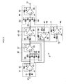
Fig. 2 is an explanatory diagram of a phase lag compensation means of the embodiment shown inFig. 1 ; -
Fig. 3 is an explanatory diagram of frequency characteristics of the phase lag compensation means of the embodiment shown inFig. 1 ; and -
Fig. 4 is an explanatory diagram of the frequency characteristics of the embodiment shown inFig. 1 . - In
Fig. 1 , anabsolute displacement sensor 1 in accordance with this embodiment is comprised of asensor housing 2 serving as a detection object; amass body 3 having a mass m (kg) which is movably supported by thesensor housing 2 with a spring coefficient k (N/m) and a damping coefficient c (Ns/m); a detecting means 4 which electrically detects a relative velocity v (= vu - vx) (m/s) of thesensor housing 2 with respect to the mass body 3 (where vx (m/s) is the absolute velocity of themass body 3 attributable to the absolute velocity vu (m/s) of the sensor housing 2); a feedback control means 5 which controls the absolute displacement x of themass body 3 attributable to the absolute displacement u of thesensor housing 2 by positively feeding back a relative displacement (u - x) obtained by integrating the relative velocity v detected by thedetecting means 4, by feeding back the detected relative velocity v negatively in this embodiment, and by negatively feeding back a relative acceleration a (m/s2) obtained by primarily differentiating the detected relative velocity v, respectively; and a phase lag compensation means 6 which performs phase lag compensation in a required frequency region with respect to the relative displacement (u - x) obtained by the integration from the feedback control means 5. - The
mass body 3 is displaceably (vibratably) supported to thesensor housing 2 by aspring 11 having the spring coefficient k (N/m), and the damping coefficient c with respect to the vibration of such amass body 3 is determined on the basis of the heat loss in the elastic deformation of thespring 11 per se and the eddy current loss in the detecting means 4. - The detecting means 4 includes a
permanent magnet 12 fixed to thesensor housing 2, acoil 13 fixed to themass body 3 so as to detect the magnetic flux of thepermanent magnet 12, and anamplifier 14 which converts a current signal i indicating the relative velocity v from thecoil 13 into a relative velocity voltage signal ev (V) as the relative velocity v with an amplification degree (current - voltage conversion coefficient) Ka (V/A). Thecoil 13 is adapted to electrically detect the relative velocity v of thesensor housing 2 with respect to themass body 3 as a change in the magnetic flux of thepermanent magnet 12 traversing thecoil 13, and the eddy current loss in the electrical detection of the change in the magnetic flux of thepermanent magnet 12 due to thecoil 13 contributes to the damping coefficient c. - The feedback control means 5 includes an
integration circuit 15 which outputs a relative displacement voltage signal eD (V) as the relative displacement (u - x) by integrating the relative velocity voltage signal ev; adifferentiation circuit 16 which outputs a relative acceleration voltage signal eA (V) as the relative acceleration a by primarily differentiating the relative velocity voltage signal eV; amultiplier 17 which outputs a voltage signal KD - eD by multiplying by a displacement feedback gain KD the relative displacement voltage signal eD obtained by integrating the relative velocity voltage signal eV; amultiplier 18 which outputs a voltage signal KV · eV by multiplying the relative velocity voltage signal eV by an velocity feedback gain KV; amultiplier 19 which outputs a voltage signal KA · eA by multiplying the relative acceleration voltage signal eA by an acceleration feedback gain KA; an adder-subtractor 20 which outputs an addition-subtraction voltage signal ec (= KD · eD - KV · eV - KA · eA) by performing addition and subtraction of the voltage signals KD · eD, KV · eV, and KA · eA from themultipliers converter 21 which converts the addition-subtraction voltage signal ec into a current signal fc with a conversion feedback gain Kf (A/V); and anelectromagnetic actuator 22 which operates by using the current signal fc from theconverter 21 as a coil drive current. - The
integration circuit 15 consists of aresistor 25 having a resistance value RD (Ω) and acapacitor 26 having an electrostatic capacity CD (F), and thedifferentiation circuit 16 consists of acapacitor 27 having an electrostatic capacity CA (F) and aresistor 28 having a resistance value RA (Ω). - The
electromagnetic actuator 22 serving as an actuator consists of acoil 29 fixed to themass body 3 and apermanent magnet 30 secured to thesensor housing 2 and generates a driving force F (N) by a current (A) inputted to thecoil 29 on the basis of the current signal fc. Theelectromagnetic actuator 22 is adapted to generate the driving force F with respect to the inputted current and to impart the driving force F to thecoil 29 relative to themass body 3 so as to displace themass body 3 relative to thesensor housing 2. It is assumed that a conversion gain for the driving force F with respect to the current signal fc is included in the conversion feedback gain Kf. - As shown in
Fig. 2 , the phase lag compensation means 6 has aninverter 41, anintegrator 42, anintegrator 43, anadder 44, aninverter 45, and aninverter 46. Theinverter 41 which inverts the relative displacement voltage signal eD inputted thereto consists ofresistors operational amplifier 53. Theintegrator 42 which integrates output signals inputted thereto from theinverters resistors capacitor 57 having an electrostatic capacity C1 (F), and anoperational amplifier 58. Theintegrator 43 which integrates an output signal inputted thereto from theintegrator 42 consists of aresistor 59 having a resistance value R6 (Ω), acapacitor 60 having an electrostatic capacity C2 (F), and anoperational amplifier 61. Theadder 44 which adds output signals inputted thereto from theinverter 41, theintegrator 43, and theinverter 46 consists ofresistors operational amplifier 66. Theinverter 45 which inverts an output signal inputted thereto from theintegrator 43 consists ofresistors operational amplifier 69. Theinverter 46 which inverts an output signal inputted thereto from theintegrator 42 consists ofresistors operational amplifier 72. - The phase lag compensation means 6 shown in
Fig. 2 has a transfer function GC(s) of a second-order system shown in Expression (1), where R1 = R2, R3 = 1/ωd 2, R4 · R6 · C1 · C2 = 1/ωd 2, R5 · C1 = 1/(2 · ξd · ωd), R10/R7 = ωd 2/ωn 2, R10/R8 = 1 - ωd 2/ωn 2, R10/R9 = 2 · ξn · (1/ωn) - 2 · ξd · (ωd/ωn 2), R11 = R12, and R13 = R14, and where ωn = 0.9 · (2π) (rad/s), ξn = 0.4, ωd = 0.1 · (2π) (rad/s), and ξd = 0.15, and has frequency characteristics shown inFig. 3 . With respect to the relative displacement voltage signal eD which is an output signal of the feedback control means 5 in which the phase advances at not more than a natural frequency ωn shown in Expression (15), the phase lag compensation means 6 is adapted to perform phase lag compensation in a required frequency region so that the advance of the phase becomes zero in the detected range. -

- In the above-described
absolute displacement sensor 1, if all are fed back negatively, the transfer function of the relative displacement voltage signal eD with respect to the absolute displacement u of thesensor housing 2 as the detection object is given by the following Expression (2): -

- In addition, the transfer function of the relative velocity voltage signal eV with respect to the absolute displacement u is given by the following Expression (3):
-

- In Expressions (2) and (3), the coefficients a0, a1, a2, a3, and a4 are expressed by the following Expressions (4) to (8):
-

- Here, TD is a time constant of the
integration circuit 15, and TA is a time constant of thedifferentiation circuit 16. A transfer function GD(s) of theintegration circuit 15 is given by the following Expression (9): -

- If TD is large, TDs » 1, so that the transfer function GD(s) is given by the following Expression (10):
-

- A transfer function GA(s) of the
differentiation circuit 16 is given by the following Expression (11): -

- In a range in which s is small, TAs « 1, so that the transfer function GA(s) is given by the following Expression (12):
-

- From Expressions (10) and (12), the transfer function of the relative displacement voltage signal eD with respect to the absolute displacement u can be expressed by the following Expression (13):
-

- Similarly, from Expressions (10) and (12), the transfer function of the relative velocity voltage signal eV with respect to the absolute displacement u can be expressed by the following Expression (14):
-

- If the natural frequency ωn and the damping ratio ζ are determined from Expression (13), the following Expressions (15) and (16) are given:
-

- The transfer function of the absolute displacement u of the
sensor housing 2 attributable to the relative displacement u - x of thesensor housing 2 is given by the Expression (17) below. The frequency response characteristics expressing this Expression (17) are given in a gain-phase diagram with feedback only inFig. 4 . InFig. 4 , ωn is determined by Expression (15), and a peak value of its frequency is determined by Expression (16). Without feedback, which is indicated by the dotted line, the gain is 0 dB, but in the case of feedback only, which is indicated by the narrow solid line, the gain dropped to -34 dB at a frequency of ωn or higher. However, at 1 Hz, the phase advanced 45°, and the measurement range of the sensor for measuring the displacement becomes approximately 2 Hz or higher. It is the phase lag compensation means 6 that expands this measurement range to an extremely low frequency. Namely, by causing ωn inFig. 4 and ωn inFig. 3 to agree with each other, the phase at 1 Hz is set to 0°, and the phase down to 0.2 Hz or thereabouts is set to the vicinity of 0°. -

- The range of detection of the absolute displacement u by the
absolute displacement sensor 1 is a region in which the frequency is the natural frequency ωn or higher and in which the magnitude (gain) of the transfer function (u - x)/u becomes constant. Accordingly, the terms which are affected at the natural frequency ωn or higher in Expression (17) are those of s2 in both the numerator and the denominator, the transfer function (u - x)/u and the detected relative displacement (u - x) at the natural frequency ωn or higher are given by the following Expression (18): -

- The relationship between, on the one hand, a detectable amplitude (detectable maximum amplitude) H (= Max · (u - x)) which can be detected by the
absolute displacement sensor 1 due to such as structural requirements inside theabsolute displacement sensor 1 and, on the other hand, a detectable amplitude (detectable maximum amplitude) U (= Max · u) of thesensor housing 2 which can be detected by theabsolute displacement sensor 1, is given by Expression (19): -

- As is apparent from the above-described analysis of the
absolute displacement sensor 1, in Expression (15), as the relative displacement feedback gain KD is varied, (k + 1/TD · Ka · Kf · KD) in the numerator term varies. Here, since 1/TD, Ka, and Kf are positive, the numerator term becomes (k - 1/TD · Ka · Kf · KD) and small owing to the positive feedback of the relative displacement (u - x) (it should be noted that, in the negative feedback of the relative displacement (u - x), the numerator term in Expression (15) becomes (k + 1/TD · Ka · Kf · KD)). - In addition, in Expression (15), as the relative acceleration feedback gain KA is varied, (m + TA · Ka · Kf · KA) in the denominator term varies. Here, since TA, Ka, and Kf are positive, the denominator term (m + TA · Ka · Kf ·KA) becomes large owing to the negative feedback of the relative acceleration a (it should be noted that, in the positive feedback of the relative acceleration a, the denominator term becomes (m - TA · Ka · Kf · KA)).
- Accordingly, in the
absolute displacement sensor 1, since the relative displacement (u - x) is fed back positively, and the relative acceleration a is fed back negatively, it is possible to lower the natural frequency ωn without causing a structural defect. - In addition, with the
absolute displacement sensor 1, as is apparent from Expression (19), since the relative acceleration a is fed back negatively, and (TA · Ka · Kf · KA) is hence adapted to become positive, even if the detectable amplitude H is small, it is possible to detect a large absolute displacement u of thesensor housing 2, i.e., it is possible to enlarge the detectable amplitude U of theabsolute displacement sensor 1. - Furthermore, with the
absolute displacement sensor 1, the feedback of the relative velocity v affects only the damping ratio ξ, and, in Expression (16), as the velocity feedback gain Kv of the relative velocity v is varied, (c + Ka · Kf · Kv) in the numerator term is adapted to vary. Here, since Ka and Kf are positive coefficients, the relative velocity v is fed back negatively, as described above, so that (c + Ka · Kf · Kv) becomes large, and the damping ratio ξ also becomes large. If the relative velocity v is fed back positively, the numerator term in Expression (16) becomes (c - Ka · Kf · Kv), making it possible to make the damping ratio ξ small by the positive feedback of the relative velocity v. - In addition, since the
absolute displacement sensor 1 is provided with the phase lag compensation means 6 for performing phase lag compensation with respect to the relative displacement (u - x) obtained by integration, it is possible to overcome a phase advancement in the vicinity of the natural frequency ωn of the transfer function (u - x)/u shown by Expression (17). Thus, it is possible to lower the natural frequency ωn, and even with a structure whose natural frequency is extremely low, its absolute displacement can be detected satisfactorily. - Incidentally, with the
absolute displacement sensor 1 using the phase lag compensation means 6 shown inFig. 2 , as is also apparent from the characteristic diagram of feedback plus phase lag compensation, indicated by the thick solid line, of the frequency response characteristics inFig. 4 , detection down to 0.2 Hz is possible. Moreover, since the gain is lowered to -34 dB, it becomes possible to detect a 50-fold displacement. For instance, even if the movable amount of themass body 3 is 1 mm, it becomes possible to detect the absolute displacement of 50 mm, so that miniaturization can be achieved. - Accordingly, with the
absolute displacement sensor 1 which implements an absolute displacement detection method wherein detection is made of the relative velocity v of thesensor housing 2 with respect to themass body 3 supported by thesensor housing 2 serving as the detection object with the spring coefficient k and the damping coefficient c, the absolute displacement x of themass body 3 attributable to the absolute displacement u of thesensor housing 2 is controlled by positively feeding back the relative displacement (u - x) obtained by integrating the detected relative velocity v, by negatively feeding back the relative acceleration a obtained by primarily differentiating the detected relative velocity v, and by negatively feeding back the detected relative velocity v, respectively, and wherein phase lag compensation is performed with respect to the relative displacement (u - x) obtained by the integration, the relative displacement (u - x) subjected to phase lag compensation and the detected relative velocity v of thesensor housing 2 can be outputted and obtained respectively from theoutput terminals - In addition, with the
absolute displacement sensor 1, since the relative velocity v of thesensor housing 2 with respect to themass body 3 is electrically detected by the detectingmeans 4, and the relative displacement (u - x) is obtained by integrating the relative velocity v detected by the detectingmeans 4, it is possible to circumvent the effect of drift caused by a dc component as compared with an absolute displacement sensor in which the relative displacement (u - x) is directly detected electrically. - With the
absolute displacement sensor 1, the relative acceleration voltage signal eA (V) of thedifferentiation circuit 16 may be outputted and obtained as the absolute acceleration.
Claims (5)
- An absolute displacement detection method comprising the steps of:detecting a relative velocity of a detection object with respect to a mass body supported by the detection object with a predetermined spring coefficient and a predetermined damping coefficient;controlling the displacement of said mass body attributable to an absolute displacement of the detection object by positively feeding back a relative displacement obtained by integrating the detected relative velocity and by negatively feeding back a relative acceleration obtained by primarily differentiating the detected relative velocity, respectively; andobtaining the absolute displacement of the detection object from a relative displacement in which the relative displacement obtained by the integration is subjected to phase lag compensation in a required frequency region.
- The absolute displacement detection method according to claim 1, wherein the displacement of said mass body attributable to the absolute displacement of the detection object is controlled by negatively or positively feeding back the detected relative velocity.
- An absolute displacement sensor comprising: a mass body which is supported by a detection object with a predetermined spring coefficient and a predetermined damping coefficient; detecting means which detects a relative velocity of the detection object with respect to said mass body; feedback control means which controls a displacement of said mass body attributable to an absolute displacement of the detection object by positively feeding back a relative displacement obtained by integrating the detected relative velocity and by negatively feeding back a relative acceleration obtained by primarily differentiating the detected relative velocity, respectively; and phase lag compensation means which performs phase lag compensation in a required frequency region with respect to the relative displacement obtained by the integration, wherein the relative displacement subjected to the phase lag compensation by said phase lag compensation means is outputted as the absolute displacement of the detection object.
- The absolute displacement sensor according to claim 3, wherein said feedback control means is adapted to control the displacement of said mass body attributable to the absolute displacement of the detection object by further negatively or positively feeding back the detected relative velocity.
- An active dynamic vibration absorber which is adapted to absorb vibrations of a vibrating body on the basis of the absolute displacement which is outputted from the absolute displacement sensor according to claim 3 or 4.
Applications Claiming Priority (2)
| Application Number | Priority Date | Filing Date | Title |
|---|---|---|---|
| JP2007204782A JP4973373B2 (en) | 2007-08-06 | 2007-08-06 | Absolute displacement detection method and absolute displacement sensor using the method |
| PCT/JP2008/002120 WO2009019863A1 (en) | 2007-08-06 | 2008-08-05 | Absolute displacement detection method and absolute displacement sensor using the method |
Publications (2)
| Publication Number | Publication Date |
|---|---|
| EP2177885A1 true EP2177885A1 (en) | 2010-04-21 |
| EP2177885A4 EP2177885A4 (en) | 2016-10-26 |
Family
ID=40341104
Family Applications (1)
| Application Number | Title | Priority Date | Filing Date |
|---|---|---|---|
| EP08790384.5A Withdrawn EP2177885A4 (en) | 2007-08-06 | 2008-08-05 | Absolute displacement detection method and absolute displacement sensor using the method |
Country Status (7)
| Country | Link |
|---|---|
| US (1) | US8418552B2 (en) |
| EP (1) | EP2177885A4 (en) |
| JP (1) | JP4973373B2 (en) |
| KR (1) | KR101300024B1 (en) |
| CN (1) | CN101790675B (en) |
| NZ (1) | NZ583164A (en) |
| WO (1) | WO2009019863A1 (en) |
Families Citing this family (17)
| Publication number | Priority date | Publication date | Assignee | Title |
|---|---|---|---|---|
| JP5322710B2 (en) * | 2009-03-06 | 2013-10-23 | 特許機器株式会社 | Servo type vibration sensor and vibration control device |
| JP5532238B2 (en) * | 2010-07-08 | 2014-06-25 | 国立大学法人東京工業大学 | Rigid body characteristic identification device and rigid body characteristic identification method |
| CN102537196B (en) * | 2010-12-24 | 2013-12-18 | 上海微电子装备有限公司 | Active vibration damping system as well as vibration damping unit and absolute displacement measuring device thereof |
| CN102749873B (en) * | 2012-07-27 | 2014-09-03 | 吉林大学 | Electromagnetic drive type phased source phase compensation control system and compensation control method |
| US9121865B2 (en) * | 2012-12-12 | 2015-09-01 | Raytheon Company | Hung mass accelerometer with differential Eddy current sensing |
| JP6451094B2 (en) * | 2014-06-16 | 2019-01-16 | 一登 背戸 | Absolute displacement sensor |
| JP6405735B2 (en) * | 2014-06-16 | 2018-10-17 | 一登 背戸 | Absolute displacement sensor |
| JP6451095B2 (en) * | 2014-06-16 | 2019-01-16 | 一登 背戸 | Absolute displacement sensor |
| JP5946074B1 (en) * | 2015-01-21 | 2016-07-05 | 国立研究開発法人防災科学技術研究所 | Absolute speed response computing device, absolute speed response computing system using the same, and absolute speed response computing method |
| US9784759B2 (en) | 2015-11-16 | 2017-10-10 | Raytheon Company | Thermally insensitive open-loop hung mass accelerometer with differential Eddy current sensing |
| US10024880B2 (en) | 2016-05-21 | 2018-07-17 | Raytheon Company | Athermal hung mass accelerometer with reduced sensitivity to longitudinal temperature gradients |
| US10668882B2 (en) * | 2018-03-30 | 2020-06-02 | Veoneer Us Inc. | Mechanical transfer function cancellation |
| CN111366231A (en) * | 2020-02-14 | 2020-07-03 | 清华大学 | Vibration measuring device |
| CN111694437B (en) * | 2020-06-20 | 2023-09-08 | 瑞声科技(新加坡)有限公司 | Method and device for realizing tactile effect, and computer-readable storage medium |
| CN112556831B (en) * | 2020-12-01 | 2021-08-27 | 南京艾泰克物联网科技有限公司 | Detection method of intelligent detection alarm device for well lid abnormity |
| CN112683384A (en) * | 2020-12-01 | 2021-04-20 | 西南交通大学 | Intelligent subway detection mechanism based on wireless charging of train travelling vibration pulse |
| CN120375478B (en) * | 2025-06-30 | 2025-09-05 | 湖南大学 | LCSS-topological feature fusion-based skateboard action recognition and interaction method |
Family Cites Families (7)
| Publication number | Priority date | Publication date | Assignee | Title |
|---|---|---|---|---|
| JPH01136033A (en) * | 1987-11-22 | 1989-05-29 | Ichiyo Wada | Signal processing circuit for pickup for measuring mechanical vibration |
| JPH02113040U (en) * | 1989-02-25 | 1990-09-10 | ||
| TW419839B (en) * | 1999-08-09 | 2001-01-21 | Nat Science Council | Device for measuring vibration and method thereof |
| JP2001148342A (en) * | 1999-11-22 | 2001-05-29 | Canon Inc | Active anti-vibration apparatus, control apparatus and method using speed sensor, exposure apparatus, and device manufacturing method |
| JP3899891B2 (en) * | 2001-10-23 | 2007-03-28 | 一登 背戸 | Absolute velocity / absolute displacement detection method and absolute velocity / absolute displacement sensor using the method |
| JP2003130629A (en) * | 2001-10-29 | 2003-05-08 | Kayaba Ind Co Ltd | Displacement measuring device and its measuring method |
| JP2004251666A (en) * | 2003-02-18 | 2004-09-09 | Kazuto Sedo | Servo type absolute displacement/velocity sensor |
-
2007
- 2007-08-06 JP JP2007204782A patent/JP4973373B2/en active Active
-
2008
- 2008-08-05 KR KR1020107002589A patent/KR101300024B1/en active Active
- 2008-08-05 US US12/672,115 patent/US8418552B2/en active Active
- 2008-08-05 EP EP08790384.5A patent/EP2177885A4/en not_active Withdrawn
- 2008-08-05 NZ NZ583164A patent/NZ583164A/en unknown
- 2008-08-05 WO PCT/JP2008/002120 patent/WO2009019863A1/en not_active Ceased
- 2008-08-05 CN CN2008801020912A patent/CN101790675B/en active Active
Non-Patent Citations (1)
| Title |
|---|
| See references of WO2009019863A1 * |
Also Published As
| Publication number | Publication date |
|---|---|
| KR20100069641A (en) | 2010-06-24 |
| WO2009019863A1 (en) | 2009-02-12 |
| NZ583164A (en) | 2011-08-26 |
| JP2009041954A (en) | 2009-02-26 |
| CN101790675A (en) | 2010-07-28 |
| CN101790675B (en) | 2013-07-24 |
| EP2177885A4 (en) | 2016-10-26 |
| JP4973373B2 (en) | 2012-07-11 |
| US20110203377A1 (en) | 2011-08-25 |
| US8418552B2 (en) | 2013-04-16 |
| KR101300024B1 (en) | 2013-08-29 |
Similar Documents
| Publication | Publication Date | Title |
|---|---|---|
| US8418552B2 (en) | Absolute displacement detection method and absolute displacement sensor using the method | |
| US8875578B2 (en) | Electronic damper circuit for MEMS sensors and resonators | |
| JP5322710B2 (en) | Servo type vibration sensor and vibration control device | |
| US20140000365A1 (en) | Vibratory gyroscope | |
| EP2867154B1 (en) | An improved resonator | |
| US8836444B2 (en) | Frequency stabilization in nonlinear MEMS and NEMS oscillators | |
| US9611139B2 (en) | Resonator | |
| Pai et al. | Non-linear vibration absorbers using higher order internal resonances | |
| US20080246200A1 (en) | Vibration Isolation System and Method | |
| JP6405735B2 (en) | Absolute displacement sensor | |
| Li et al. | Control of loudspeakers using disturbance-observer-type velocity estimation | |
| JP6451095B2 (en) | Absolute displacement sensor | |
| JP2006023287A (en) | Measuring method of jerk (jerk) using piezoelectric material | |
| JP6451094B2 (en) | Absolute displacement sensor | |
| JP3899891B2 (en) | Absolute velocity / absolute displacement detection method and absolute velocity / absolute displacement sensor using the method | |
| CN112003584B (en) | Micro-resonator control system based on time lag feedback | |
| Polóni et al. | Adaptive model estimation of vibration motion for a nanopositioner with moving horizon optimized extended Kalman filter | |
| Fenik et al. | Optimal PI controller with position feedback for vibration suppression | |
| Jalili et al. | A new approach to semi-active vibration suppression using adjustable inertia absorbers | |
| Kumar et al. | Design and simulation of mems based gyroscope | |
| JPS58221038A (en) | Vibration-proof device | |
| Zheng et al. | Disturbance rejection in MEMS gyroscope: Problems and solutions | |
| CN121164737A (en) | Self-adaptive MEMS electric field sensor and system | |
| JPH0658013A (en) | Vibration control device | |
| CN121275125A (en) | Dual-MEMS capacitance pendulum dual-parameter acceleration and speed output sensor |
Legal Events
| Date | Code | Title | Description |
|---|---|---|---|
| PUAI | Public reference made under article 153(3) epc to a published international application that has entered the european phase |
Free format text: ORIGINAL CODE: 0009012 |
|
| 17P | Request for examination filed |
Effective date: 20100202 |
|
| AK | Designated contracting states |
Kind code of ref document: A1 Designated state(s): AT BE BG CH CY CZ DE DK EE ES FI FR GB GR HR HU IE IS IT LI LT LU LV MC MT NL NO PL PT RO SE SI SK TR |
|
| AX | Request for extension of the european patent |
Extension state: AL BA MK RS |
|
| DAX | Request for extension of the european patent (deleted) | ||
| RA4 | Supplementary search report drawn up and despatched (corrected) |
Effective date: 20160926 |
|
| RIC1 | Information provided on ipc code assigned before grant |
Ipc: G01V 1/18 20060101AFI20160920BHEP Ipc: G01H 1/00 20060101ALN20160920BHEP |
|
| STAA | Information on the status of an ep patent application or granted ep patent |
Free format text: STATUS: EXAMINATION IS IN PROGRESS |
|
| 17Q | First examination report despatched |
Effective date: 20180924 |
|
| STAA | Information on the status of an ep patent application or granted ep patent |
Free format text: STATUS: THE APPLICATION HAS BEEN WITHDRAWN |
|
| 18W | Application withdrawn |
Effective date: 20190115 |