EP2177764A1 - Scroll fluid machine - Google Patents
Scroll fluid machine Download PDFInfo
- Publication number
- EP2177764A1 EP2177764A1 EP08792459A EP08792459A EP2177764A1 EP 2177764 A1 EP2177764 A1 EP 2177764A1 EP 08792459 A EP08792459 A EP 08792459A EP 08792459 A EP08792459 A EP 08792459A EP 2177764 A1 EP2177764 A1 EP 2177764A1
- Authority
- EP
- European Patent Office
- Prior art keywords
- annular
- scroll
- sealing member
- sealing
- annular plate
- Prior art date
- Legal status (The legal status is an assumption and is not a legal conclusion. Google has not performed a legal analysis and makes no representation as to the accuracy of the status listed.)
- Withdrawn
Links
Images


Classifications
-
- F—MECHANICAL ENGINEERING; LIGHTING; HEATING; WEAPONS; BLASTING
- F04—POSITIVE - DISPLACEMENT MACHINES FOR LIQUIDS; PUMPS FOR LIQUIDS OR ELASTIC FLUIDS
- F04C—ROTARY-PISTON, OR OSCILLATING-PISTON, POSITIVE-DISPLACEMENT MACHINES FOR LIQUIDS; ROTARY-PISTON, OR OSCILLATING-PISTON, POSITIVE-DISPLACEMENT PUMPS
- F04C18/00—Rotary-piston pumps specially adapted for elastic fluids
- F04C18/02—Rotary-piston pumps specially adapted for elastic fluids of arcuate-engagement type, i.e. with circular translatory movement of co-operating members, each member having the same number of teeth or tooth-equivalents
- F04C18/0207—Rotary-piston pumps specially adapted for elastic fluids of arcuate-engagement type, i.e. with circular translatory movement of co-operating members, each member having the same number of teeth or tooth-equivalents both members having co-operating elements in spiral form
- F04C18/0215—Rotary-piston pumps specially adapted for elastic fluids of arcuate-engagement type, i.e. with circular translatory movement of co-operating members, each member having the same number of teeth or tooth-equivalents both members having co-operating elements in spiral form where only one member is moving
-
- F—MECHANICAL ENGINEERING; LIGHTING; HEATING; WEAPONS; BLASTING
- F04—POSITIVE - DISPLACEMENT MACHINES FOR LIQUIDS; PUMPS FOR LIQUIDS OR ELASTIC FLUIDS
- F04C—ROTARY-PISTON, OR OSCILLATING-PISTON, POSITIVE-DISPLACEMENT MACHINES FOR LIQUIDS; ROTARY-PISTON, OR OSCILLATING-PISTON, POSITIVE-DISPLACEMENT PUMPS
- F04C27/00—Sealing arrangements in rotary-piston pumps specially adapted for elastic fluids
- F04C27/005—Axial sealings for working fluid
-
- F—MECHANICAL ENGINEERING; LIGHTING; HEATING; WEAPONS; BLASTING
- F04—POSITIVE - DISPLACEMENT MACHINES FOR LIQUIDS; PUMPS FOR LIQUIDS OR ELASTIC FLUIDS
- F04C—ROTARY-PISTON, OR OSCILLATING-PISTON, POSITIVE-DISPLACEMENT MACHINES FOR LIQUIDS; ROTARY-PISTON, OR OSCILLATING-PISTON, POSITIVE-DISPLACEMENT PUMPS
- F04C23/00—Combinations of two or more pumps, each being of rotary-piston or oscillating-piston type, specially adapted for elastic fluids; Pumping installations specially adapted for elastic fluids; Multi-stage pumps specially adapted for elastic fluids
- F04C23/008—Hermetic pumps
Definitions
- the present invention relates to a scroll-type fluid machine having a partitioned configuration in which a back-pressure chamber to which high-pressure gas is introduced is formed at the back side of a revolving scroll member.
- the scroll-type fluid machine forms a working gas chamber by combined paired fixed scroll member and revolving scroll member, which are formed by vertically mounting spiral wraps on end plates, with their phases shifted.
- the gas pressure in the working gas chamber acts in a direction to separate the fixed scroll member and the revolving scroll member. In this way, the distance between the tips of the spiral wraps increases, causing gas leakage.
- a back-pressure chamber in which high-pressure gas is introduced is partitioned at the back side of the revolving scroll member, and the revolving scroll member is pushed toward the fixed scroll member by the gas pressure. It is known that, by doing so, gas leakage can be decreased, and high efficiency can be achieved.
- Patent Document 1 To form the back-pressure chamber on the back side of the revolving scroll member, the back-pressure chamber must be partitioned and sealed off from the surroundings.
- a sealing structure proposed in Patent Document 1 has a configuration in which a groove is formed in a fixed support member supporting the back side of a revolving scroll member, a ring-shaped sealing member (back-pressure partitioning belt) and a spring member are installed in this groove, and the sealing member is pushed by the spring member toward the revolving scroll member.
- a sealing member it is necessary that the sealing member be provided with a divided surface. Therefore, gas leakage from the divided surface is a serious problem.
- Patent Document 2 proposes using a sealing member in which a so-called annular U sealing member, which has a sliding surface on one side in contact with a revolving scroll member and which has an angular-U-shaped cross-section, is installed horizontally (in a direction parallel to the sliding direction of the revolving scroll member) such that its opening faces a back-pressure chamber and such that the sliding surface is pushed against the revolving scroll member by an internal pre-load spring of the annular U sealing member.
- a pre-load spring is provided inside a U sealing member so as to pull both edges of an opening outward. Therefore, when the U sealing member is used as the sealing member of a back-pressure chamber, it is difficult to control the size, including a sliding surface, in the height direction, and uneven pre-load forces are applied to the revolving scroll member by pushing the sliding surface, thus causing the sliding loss to increase.
- the annular U sealing member is laterally installed such that its side surface is parallel to the sliding direction of the revolving scroll member; therefore, there are problems in that the sliding surface area of the sealing member increases, the sliding loss increases, the installation space in the sliding direction of the sealing member, i.e., the installation space in the radial direction of the scroll member, increases, and thus the design freedom is reduced.
- the present invention has been conceived in light of such problems, and it is an object thereof to provide a scroll-type fluid machine that facilitates the formation of a back-pressure chamber so as to increase the design freedom by reducing, as much as possible, the installation space of the sealing member partitioning the back-pressure chamber in a space on the back side of the revolving scroll member, where it is difficult to ensure sufficient space.
- the scroll-type fluid machine according to the present invention provides the following solutions.
- the scroll-type fluid machine according to the present invention includes a fixed scroll member; a revolving scroll member assembled so as to be capable of being orbitally driven with respect to the fixed scroll member and constituting a working gas chamber; and a fixed support member that supports the back side of the revolving scroll member, wherein a back-pressure chamber to which high-pressure gas is introduced is partitioned between the revolving scroll member and the fixed support member, and wherein the sealing member is constructed of an annular U sealing member, the annular U sealing member is oriented in a direction orthogonal to the back side of the revolving scroll member, and a side surface contacts a sealed surface of the fixed support member.
- the sealing member partitioning the back-pressure chamber is constructed of the annular U sealing member, the annular U sealing member is oriented in a direction orthogonal to the back side of the revolving scroll member, and the one side surface contacts the sealing surface of the fixed support member; therefore, gas leakage from the back-pressure chamber can be reduced, the gas pressure in the back-pressure chamber can be kept constant, and the installation space in the radial direction of the sealing member can be reduced.
- the sealing member may include an annular plate member that has a sliding surface on which the back side of the revolving scroll member slides and a sealed surface to which the other side of the annular U sealing member contacts and that is formed with an L-shaped cross-section.
- the size of the sealing member can be controlled by the sealing surface height of the fixed support member and the height of the annular plate member. In this way, size control can be facilitated by eliminating the effect of the internal pre-load spring of the annular U sealing members, and thus a highly accurate annular back-pressure chamber and sealing member having no variations and having stable performance can be constructed.
- the width of the sliding surface of the annular plate member may be substantially equal to the width of the annular U sealing member.
- the sliding surface width of the annular plate member is substantially equal to the width of the annular U sealing member, which is oriented in a direction orthogonal to the back side of the revolving scroll member; therefore, the sliding surface width can be reduced compared to that matched to the side surface length of the annular U sealing member. In this way, the area of the sliding surface of the annular plate member can be reduced, the sliding loss when the revolving scroll member slides can be reduced, and high efficiency can be achieved.
- the back-pressure chamber may be an annular back-pressure chamber on which the sealing member is mounted on each of the outward side and inward side, and each of the sealing members may include the annular U sealing member and/or the annular plate member.
- each of the sealing members on the outward side and the inward side includes the annular U sealing member and/or the annular plate member; therefore, gas leakage from the back-pressure chamber decreases, the gas pressure in the back-pressure chamber can be kept constant, the installation space in the radial direction of the sealing members on the outward side and the inward side can be reduced as much as possible, the formation of the back-pressure chamber can be facilitated on the back side of the revolving scroll member, where it is difficult to ensure sufficient space, and thus the design degree can be increased. In this way, size reduction, high efficiency, and high performance of the scroll-type fluid machine can be achieved.
- the annular plate member may be constructed of an integrated annular plate member provided with a sealed surface on which the other side of the annular U sealing member contacts the outward side and inward side thereof.
- annular U sealing members can be installed on the outward side and the inward side together with an integrated annular plate member, the number of components can be reduced, and the sealing performance of the sealing members and the sliding performance of the revolving scroll member can be improved. In this way, gas leakage from the back-pressure chamber and sliding loss when the revolving scroll member slides can be reduced even more, and thus high efficiency can be achieved.
- a chamfer may be formed at a tip of the sealed surface of the annular plate member on which the annular U sealing member contacts.
- a chamfer is formed on the tip of the sealed surface of the annular plate member where the annular U sealing member contacts; therefore, the annular plate member can be easily inserted into the annular U sealing member. In this way, assembly of the annular U sealing member and the annular plate member can be facilitated.
- a resilient member that pushes the sliding surface of the annular plate member to the back side of the revolving scroll member may be mounted between the annular plate member and the fixed support member.
- a resilient member is installed between the annular plate member and the fixed support member, and the back side of the revolving scroll member is pushed with the annular plate member; therefore, a pre-load can be applied to the revolving scroll member without applying a pre-load to the annular U sealing member. In this way, damage caused by applying an excessive load to the annular U sealing member can be prevented, and thus the durability can be improved.
- the installation space of the sealing members can be reduced as much as possible, the formation of the back-pressure chamber can be facilitated on the back side of the revolving scroll member, where it is difficult to ensure sufficient space, and thus the design freedom can be increased.
- facilitation of the formation of the annular back-pressure chamber which is crucial for achieving high efficiency, can contribute greatly to the size reduction and performance enhancement of the scroll compressor.
- Fig. 1 is a longitudinal sectional view of a scroll compressor 1, which is an example of a scroll-type fluid machine.
- a scroll compressor 1 for refrigerant compression will be described.
- the present invention is not limited to this scroll compressor 1 for refrigerant compression.
- the scroll compressor 1 includes a sealed housing 10.
- An electric motor 4 constructed of a stator 5 and a rotor 6 is securely mounted at the lower section inside the sealed housing 10, and a scroll compressing mechanism 3 is securely mounted at the upper section.
- a crank shaft 7 is integrated with the rotor 6.
- a feeding hole 7A is formed at the shaft center in the axial direction of the crank shaft 7 so as to enable force feeding of a lubricant contained in the bottom section of the sealed housing 10 through the feeding hole 7 with a feeding pump (not shown), which is installed at the lower edge of the crank shaft 7, to sites requiring lubrication, such as bearings of the scroll compressing mechanism 3.
- the scroll compressing mechanism 3 is constructed of a fixed support member 31 on which a bearing 30 supporting the crank shaft 7 is provided and which is fixed to the sealed housing 10; a paired fixed scroll member 32 and revolving scroll member 33, which include spiral wraps 32B and 33B, respectively, vertically mounted on end plates 32A and 33A, respectively, and which constitute a compression chamber 34 by assembling the engaged spiral wraps 32B and 33B on the fixed support member 31; a revolving boss section 35 that joins the revolving scroll member 33 and a crank pin 7B provided at an end of the crank shaft 7 and that orbitally drives the revolving scroll member 33; a rotation prevention mechanism 36 provided between the revolving scroll member 33 and the fixed support member 31 and constructed of an Oldham ring etc.
- the above-described scroll compressing mechanism 3 is constructed to take in low-pressure refrigerant gas, which has been drawn into the sealed housing 10 through a suction pipe (not shown), into the compression chamber 34 and release this low-pressure refrigerant gas into the discharge chamber 38 through the discharge valve after compressing it to a high pressure state by orbitally driving the revolving scroll member 33.
- This high-temperature, high-pressure refrigerant gas is guided outside the compressor from the discharge chamber 38 through a discharge pipe 40.
- An annular back-pressure chamber 50 in which high-pressure refrigerant gas (high-pressure working gas) is introduced is constructed further inward than the rotation prevention mechanism 36, between the back side of the revolving scroll member 33 and a thrust supporting surface of the fixed support member 31, by processing the thrust supporting surface of the fixed support member 31 into a depressed shape.
- An annular plate member 52 constituting a sealing member 51 is engaged with the inside of the annular back-pressure chamber 50 in the vertical direction in the drawing (a direction orthogonal to the back side of the revolving scroll member 33) in such a manner that it can slide by a minute distance.
- a depression 52A is provided on the upper surface of the annular plate member 52, and the remaining surface is a sliding surface 52B that is in contact with the back side of the end plate 33A of the revolving scroll member 33.
- Gas introducing holes 52C that penetrate the annular plate member 52 are formed at a plurality of locations around the circumferential direction on the bottom surface of the depression 52A.
- Sealed surfaces 52D and 52E with L-shaped cross-sections for mounting annular U sealing members 53 are respectively formed on an outward side surface and an inward side surface of the annular plate member 52.
- Tapered chamfers 52F and 52G are provided at the tips of the sealed surfaces 52D and 52E.
- This annular plate member 52 is pushed against the back side of the revolving scroll member 33 by the spring force of a resilient member (pre-load flat spring) 54 provided on the bottom surface of the back-pressure chamber 50 so that a pre-load is applied to the revolving scroll member 33.
- a resilient member pre-load flat spring
- Each annular U sealing member 53 has a U-shaped (or ⁇ shaped) lateral cross-section and an endless ring structure, and a pre-load spring 53A is provided therein.
- side surfaces are oriented in the vertical direction in the drawing, i.e., a direction orthogonal to the back side of the revolving scroll member 33, with the opening facing downward such that the side surfaces are disposed between and contact an outward side surface (sealed surface) 50A and an inward side surface (sealed surface) 50B of the annular back-pressure chamber 50 and the sealed surfaces 52D and 52E of the annular plate member 52.
- the sealing member 51 for partitioning and sealing off the annular back-pressure chamber 50 from the surroundings is constructed of the annular U sealing members 53 and the annular plate member 52. Then, the annular back-pressure chamber 50 constructed as described above is constructed such that high-pressure refrigerant gas (high-pressure working gas) from the compression chamber 34 is introduced through a back-pressure gas introducing path 55 provided on the end plate 33A of the revolving scroll member 33.
- the above-described configuration according to this embodiment has the following advantages.
- the annular plate member 52 is pushed against the back side of the revolving scroll member 33 by the spring force of the resilient member (pre-load flat spring) 54 and applies a pre-load to the revolving scroll member 33. Therefore, the revolving scroll member 33 is pushed against the fixed scroll member 32 so as to seal the tip surfaces of the spiral wraps 32B and 33B. In this way, upon starting the compression operation, gas leakage of the compressed refrigerant gas from the tip surfaces is prevented.
- the pressure inside the compression chamber 34 increases, and the inner pressure applies a force in a direction separating the fixed scroll member 32 and the revolving scroll member 33 from each other.
- the high-pressure refrigerant gas (high-pressure working gas) inside the compression chamber 34 is introduced into the annular back-pressure chamber 50 through the back-pressure gas introducing path 55.
- the high-pressure refrigerant gas acts upon the lower surface of the annular plate member 52, and acts to push the annular plate member 52 upward so as to push the revolving scroll member 33 toward the fixed scroll member 32.
- the revolving scroll member 33 is orbitally driven, and the back side thereof slides on the thrust supporting surface of the fixed support member 31. Since the annular plate member 52 contacts the back side of the revolving scroll member 33 and is pushed upward, the sliding surface is effectively limited to the sliding surfaces 52B of the annular plate member 52. In this way, the area on which the revolving scroll member 33 contacts and slides can be reduced, and a sliding loss caused by the orbital driving can be reduced to achieve high efficiency.
- the sealing member 51 which partitions the annular back-pressure chamber 50, is constructed of the annular U sealing members 53, and the annular U sealing members 53 are oriented in a direction orthogonal to the back side of the revolving scroll member 33 such that one side surface is in contact with the outward side surface (sealed surface) 50A and the inward side surface (sealed surface) 50B; therefore, gas leakage from the annular back-pressure chamber 50 can be reduced, the gas pressure inside the annular back-pressure chamber 50 can be kept constant, and the installation space of the sealing member 51 in the radial direction can be reduced.
- the sealing member 51 includes an integrated annular plate member 52 having two sliding surfaces 52B sandwiching the depression 52A and two sealed surfaces 52D and 52E on the outward side and the inward side; therefore, the size of the sealing member 51 can be controlled by the height of the side surfaces (sealed surfaces) 50A and 50B of the annular back-pressure chamber 50 and the height of the annular plate member 52. In this way, size control can be facilitated by eliminating the effect of the internal pre-load spring 53A of the annular U sealing members 53, and thus a highly precise annular back-pressure chamber 50 and sealing member 51 having no variations and having stable performances can be constructed.
- annular plate member 52 Since the annular plate member 52 is integrated, the number of components can be reduced, and the sealing performance of the sealing member 51 and sliding performance of the revolving scroll member 33 can be improved. Moreover, gas leakage from the annular back-pressure chamber 50 and a sliding loss caused when the revolving scroll member 33 slides can be reduced even more so as to achieve high efficiency.
- the annular plate member 52 can be easily inserted into the annular U sealing members 53, thus facilitating assembly of the annular U sealing members 53 and the annular plate member 52. Since the resilient member 54 is disposed between the annular plate member 52 and the bottom surface of the annular back-pressure chamber 50 and the back side of the revolving scroll member 33 is pushed by the annular plate member 52, a pre-load can be applied to the revolving scroll member 33 without applying a pre-load to the annular U sealing members 53.
- the seal between the tip surfaces of the spiral wraps 32B and 33B can be maintained, gas leakage of compressed refrigerant gas from the tip surfaces can be prevented, damage of the annular U sealing members 53 caused by applying an excessive load can be prevented, and the durability can be improved.
- FIG. 3 a second embodiment of the present invention will be described with reference to Fig. 3 .
- This embodiment differs from the above-described first embodiment in the configuration of an annular back-pressure chamber 60 and a sealing member 61. Since other aspects are the same as those in the first embodiment, descriptions thereof are omitted.
- the sealing member 61 is disposed on the inward side of a rotation prevention mechanism 36 on a thrust supporting surface of a fixed support member 31, and the entire area on the inward side comprises the back-pressure chamber 60.
- a shoulder section 60A for mounting the sealing member 61 is provided on the inner circumference of a depression accommodating a boss section 35 of a fixed support member 31, and an annular plate member 62 and an annular U sealing member 53 constituting the sealing member 61 are mounted on this shoulder section 60A.
- the annular U sealing member 53 is mounted such that side surfaces are oriented in the vertical direction in the drawing, i.e., a direction orthogonal to the back side of the revolving scroll member 33, and with the opening facing downward such that one side surface is in contact with a side surface (sealed surface) of the shoulder section 60A of the fixed support member 31.
- the annular plate member 62 supporting the annular U sealing member 53 has a sliding surface 62A on which the back side of the revolving scroll member 33 slides and a sealed surface 62B where the other side surface of the annular U sealing member 53 contacts, forming an L-shaped cross section, and is mounted on the shoulder section 60A by being inserted at the inner circumference of the annular U sealing member 53 and integrated therewith.
- the annular U sealing member 53 is oriented in a direction orthogonal to the back side of the revolving scroll member 33 and is mounted such that a side surface thereof is in contact with a side surface (sealed surface) of the shoulder section 60A of the fixed support member 31; therefore, gas leakage from the annular back-pressure chamber 60 can be reduced, the gas pressure inside the annular back-pressure chamber 60 can be kept constant, and the installation space of the sealing member 61 in the radial direction can be reduced. Therefore, the same advantages as those according to the above-described first embodiment can be achieved.
- the size in the height direction of the sealing member 61 can be controlled by a height h1 of the annular plate member 62 and a side surface height h2 of the shoulder section 60A of the fixed support member 31, the effect of a pre-load spring 53A of the annular U sealing member 53 can be eliminated, and size control of the sealing member 61 is facilitated. Therefore, highly accurate annular back-pressure chamber 60 and sealing member 61 having no variations and having stable performance can be constructed.
- a third embodiment of the present invention will be described with reference to Fig. 4 .
- This embodiment differs from the above-described second embodiment in the configuration of a sliding surface 72A of an annular plate member 62. Since other aspects are the same as those in the first and second embodiments, descriptions thereof are omitted.
- a width W1 of the sliding surface 72A of the annular plate member 62 on which the back side of a revolving scroll member 33 slides is substantially equal to a width W2 of a annular U sealing member 53.
- the width W1 of the sliding surface 72A of the annular plate member 62 can be reduced compared to that matched to the side surface length of the annular U sealing member 53. Therefore, the area of the sliding surface 72A of the annular plate member 62 can be reduced, and the sliding loss generated when the revolving scroll member 33 slides can be reduced so as to achieve high efficiency.
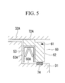
- a fourth embodiment of the present invention will be described with reference to Fig. 5 .
- This embodiment differs from the above-described second and third embodiments in that a resilient member 74 that pushes an annular plate member 62 against the back side of a revolving scroll member 33 is provided. Since other aspects are the same as those in the first to third embodiments, descriptions thereof are omitted.
- the resilient member (pre-load flat spring) 74 is provided between a step surface of the shoulder section 60A of a fixed support member 31 and the annular plate member 62, and a pre-load is applied to the revolving scroll member 33 by pushing the back side of the revolving scroll member 33 with the annular plate member 62.
- the resilient member (pre-load flat spring) 74 is provided between a step surface of the shoulder section 60A of the fixed support member 31 and the annular plate member 62, and a pre-load is applied to the revolving scroll member 33 by pushing the back side of the revolving scroll member 33 with the annular plate member 62; therefore, a pre-load can be applied to the revolving scroll member 33, without applying a pre-load to the annular U sealing member 53. Therefore, upon starting the compression operation, the seal between the tip surfaces of spiral wraps 32B and 33B can be maintained, gas leakage of compressed refrigerant gas from the tip surfaces can be prevented, damage of the annular U sealing member 53 caused by an excessive load can be prevented, and the durability can be improved.
- the present invention is not limited to the above-described embodiments, and various modifications may be made so long as they do not depart from the spirit of the invention.
- examples in which the above-described embodiments are applied to a scroll compressor for refrigerant compression have been described.
- the present invention may be applied to compressors for other uses and even to a wide range of scroll-type fluid machines other than compressors, such as expansion devices and fluid pumps.
- it may be applied not only to single-stage compressors but also to multi-stage compressors.
- the annular plate member and the annular U sealing member are not limited and may be made of either resin or metal.
- a chamfer may be provided at the tip of the sealed surface 62B of the annular plate member 62.
Landscapes
- Engineering & Computer Science (AREA)
- Mechanical Engineering (AREA)
- General Engineering & Computer Science (AREA)
- Rotary Pumps (AREA)
- Applications Or Details Of Rotary Compressors (AREA)
Abstract
Description
- The present invention relates to a scroll-type fluid machine having a partitioned configuration in which a back-pressure chamber to which high-pressure gas is introduced is formed at the back side of a revolving scroll member.
- The scroll-type fluid machine forms a working gas chamber by combined paired fixed scroll member and revolving scroll member, which are formed by vertically mounting spiral wraps on end plates, with their phases shifted. With such a scroll-type fluid machine, the gas pressure in the working gas chamber acts in a direction to separate the fixed scroll member and the revolving scroll member. In this way, the distance between the tips of the spiral wraps increases, causing gas leakage. As a countermeasure, a back-pressure chamber in which high-pressure gas is introduced is partitioned at the back side of the revolving scroll member, and the revolving scroll member is pushed toward the fixed scroll member by the gas pressure. It is known that, by doing so, gas leakage can be decreased, and high efficiency can be achieved.
- To form the back-pressure chamber on the back side of the revolving scroll member, the back-pressure chamber must be partitioned and sealed off from the surroundings. Such a sealing structure proposed in Patent Document 1 has a configuration in which a groove is formed in a fixed support member supporting the back side of a revolving scroll member, a ring-shaped sealing member (back-pressure partitioning belt) and a spring member are installed in this groove, and the sealing member is pushed by the spring member toward the revolving scroll member. However, when such a sealing member is used, it is necessary that the sealing member be provided with a divided surface. Therefore, gas leakage from the divided surface is a serious problem.
- Patent Document 2 proposes using a sealing member in which a so-called annular U sealing member, which has a sliding surface on one side in contact with a revolving scroll member and which has an angular-U-shaped cross-section, is installed horizontally (in a direction parallel to the sliding direction of the revolving scroll member) such that its opening faces a back-pressure chamber and such that the sliding surface is pushed against the revolving scroll member by an internal pre-load spring of the annular U sealing member.
-
- Patent Document 1:
- Japanese Unexamined Patent Application, Publication No.
HEI-08-61258
- Japanese Unexamined Patent Application, Publication No.
- Patent Document 2:
- Japanese Unexamined Patent Application, Publication No.
2002-54583
- Japanese Unexamined Patent Application, Publication No.
- However, usually, a pre-load spring is provided inside a U sealing member so as to pull both edges of an opening outward. Therefore, when the U sealing member is used as the sealing member of a back-pressure chamber, it is difficult to control the size, including a sliding surface, in the height direction, and uneven pre-load forces are applied to the revolving scroll member by pushing the sliding surface, thus causing the sliding loss to increase. The annular U sealing member is laterally installed such that its side surface is parallel to the sliding direction of the revolving scroll member; therefore, there are problems in that the sliding surface area of the sealing member increases, the sliding loss increases, the installation space in the sliding direction of the sealing member, i.e., the installation space in the radial direction of the scroll member, increases, and thus the design freedom is reduced.
- In particular, recently, high-pressure, high-density refrigerants are used for scroll compressors for freezing or air conditioning. In such cases, since the volume can be reduced, the outer diameter of the scroll member can be reduced, and thus the size of the compressor can be reduced. Thus, it is a significant problem to ensure a sufficient installation space for the sealing member forming the back-pressure chamber in a support surface space on the fixed support member side, where a thrust bearing surface supporting the back side of the revolving scroll member and a rotation prevention mechanism are provided.
- The present invention has been conceived in light of such problems, and it is an object thereof to provide a scroll-type fluid machine that facilitates the formation of a back-pressure chamber so as to increase the design freedom by reducing, as much as possible, the installation space of the sealing member partitioning the back-pressure chamber in a space on the back side of the revolving scroll member, where it is difficult to ensure sufficient space.
- To solve the above-described problems, the scroll-type fluid machine according to the present invention provides the following solutions.
Specifically, the scroll-type fluid machine according to the present invention includes a fixed scroll member; a revolving scroll member assembled so as to be capable of being orbitally driven with respect to the fixed scroll member and constituting a working gas chamber; and a fixed support member that supports the back side of the revolving scroll member, wherein a back-pressure chamber to which high-pressure gas is introduced is partitioned between the revolving scroll member and the fixed support member, and wherein the sealing member is constructed of an annular U sealing member, the annular U sealing member is oriented in a direction orthogonal to the back side of the revolving scroll member, and a side surface contacts a sealed surface of the fixed support member. - According to the present invention, the sealing member partitioning the back-pressure chamber is constructed of the annular U sealing member, the annular U sealing member is oriented in a direction orthogonal to the back side of the revolving scroll member, and the one side surface contacts the sealing surface of the fixed support member; therefore, gas leakage from the back-pressure chamber can be reduced, the gas pressure in the back-pressure chamber can be kept constant, and the installation space in the radial direction of the sealing member can be reduced. In this way, working gas leakage from the tip surfaces of both scroll members can be suppressed, and high efficiency and high performance can be achieved, the installation space of the sealing member can be reduced as much as possible, thus facilitating the formation of the back-pressure chamber on the back side of the revolving scroll member, where it is difficult to ensure sufficient space, and the design freedom can be increased. In particular, with a scroll compressor that allows the external diameter to be reduced by using high-pressure, high-density working gas, facilitation of the formation of the annular back-pressure chamber, which is crucial for achieving high efficiency, can contribute greatly to the size reduction and performance enhancement of the scroll compressor.
- In the scroll-type fluid machine according to the present invention, the sealing member may include an annular plate member that has a sliding surface on which the back side of the revolving scroll member slides and a sealed surface to which the other side of the annular U sealing member contacts and that is formed with an L-shaped cross-section.
- According to this configuration, because the annular plate member having a sliding surface and a sealed surface and having an L-shaped cross-section is provided, the size of the sealing member can be controlled by the sealing surface height of the fixed support member and the height of the annular plate member. In this way, size control can be facilitated by eliminating the effect of the internal pre-load spring of the annular U sealing members, and thus a highly accurate annular back-pressure chamber and sealing member having no variations and having stable performance can be constructed.
- In the scroll-type fluid machine according to the present invention, the width of the sliding surface of the annular plate member may be substantially equal to the width of the annular U sealing member.
- According to this configuration, the sliding surface width of the annular plate member is substantially equal to the width of the annular U sealing member, which is oriented in a direction orthogonal to the back side of the revolving scroll member; therefore, the sliding surface width can be reduced compared to that matched to the side surface length of the annular U sealing member. In this way, the area of the sliding surface of the annular plate member can be reduced, the sliding loss when the revolving scroll member slides can be reduced, and high efficiency can be achieved.
- In the scroll-type fluid machine according to the present invention, the back-pressure chamber may be an annular back-pressure chamber on which the sealing member is mounted on each of the outward side and inward side, and each of the sealing members may include the annular U sealing member and/or the annular plate member.
- When forming the annular back-pressure chamber, it is necessary to install sealing members on the outward side and the inward side of the back-pressure chamber. According to the above-described configuration, each of the sealing members on the outward side and the inward side includes the annular U sealing member and/or the annular plate member; therefore, gas leakage from the back-pressure chamber decreases, the gas pressure in the back-pressure chamber can be kept constant, the installation space in the radial direction of the sealing members on the outward side and the inward side can be reduced as much as possible, the formation of the back-pressure chamber can be facilitated on the back side of the revolving scroll member, where it is difficult to ensure sufficient space, and thus the design degree can be increased. In this way, size reduction, high efficiency, and high performance of the scroll-type fluid machine can be achieved.
- In the scroll-type fluid machine according to the present invention, the annular plate member may be constructed of an integrated annular plate member provided with a sealed surface on which the other side of the annular U sealing member contacts the outward side and inward side thereof.
- According to this configuration, since the annular U sealing members can be installed on the outward side and the inward side together with an integrated annular plate member, the number of components can be reduced, and the sealing performance of the sealing members and the sliding performance of the revolving scroll member can be improved. In this way, gas leakage from the back-pressure chamber and sliding loss when the revolving scroll member slides can be reduced even more, and thus high efficiency can be achieved.
- In the scroll-type fluid machine according to the present invention, a chamfer may be formed at a tip of the sealed surface of the annular plate member on which the annular U sealing member contacts.
- According to this configuration, a chamfer is formed on the tip of the sealed surface of the annular plate member where the annular U sealing member contacts; therefore, the annular plate member can be easily inserted into the annular U sealing member. In this way, assembly of the annular U sealing member and the annular plate member can be facilitated.
- In the scroll-type fluid machine according to the present invention, a resilient member that pushes the sliding surface of the annular plate member to the back side of the revolving scroll member may be mounted between the annular plate member and the fixed support member.
- According to this configuration, a resilient member is installed between the annular plate member and the fixed support member, and the back side of the revolving scroll member is pushed with the annular plate member; therefore, a pre-load can be applied to the revolving scroll member without applying a pre-load to the annular U sealing member. In this way, damage caused by applying an excessive load to the annular U sealing member can be prevented, and thus the durability can be improved.
- According to the present invention, the installation space of the sealing members can be reduced as much as possible, the formation of the back-pressure chamber can be facilitated on the back side of the revolving scroll member, where it is difficult to ensure sufficient space, and thus the design freedom can be increased. In particular, with a scroll compressor that allows the external diameter to be reduced by using high-pressure, high-density working gas, facilitation of the formation of the annular back-pressure chamber, which is crucial for achieving high efficiency, can contribute greatly to the size reduction and performance enhancement of the scroll compressor.
-
- [
FIG. 1] Fig. 1 is a longitudinal sectional view of a scroll compressor according to a first embodiment of the present invention. - [
Fig. 2] Fig. 2 is a partially enlarged longitudinal sectional view of the scroll compressor shown inFig. 1 . - [
Fig. 3] Fig. 3 is a partially enlarged longitudinal sectional view of a scroll compressor according to a second embodiment of the present invention. - [
Fig. 4] Fig. 4 is a partially enlarged longitudinal sectional view of a scroll compressor according to a third embodiment of the present invention. - [
Fig. 5] Fig. 5 is a partially enlarged longitudinal sectional view of a scroll compressor according to a fourth embodiment of the present invention. -
- 1: scroll compressor
- 3: scroll compressing mechanism
- 31: fixed support member
- 32: fixed scroll member
- 33: revolving scroll member
- 34: compressing chamber (working gas chamber)
- 50, 60: back-pressure chamber
- 50A, 50B: side surface (sealed surface)
- 51, 61: sealing member
- 52, 62: annular plate member
- 52B, 62A, 72A: sliding surface
- 52D, 52E, 62B: sealed surface
- 52F, 52G: chamfer
- 53: annular U sealing member
- 54: elastic member
- W1: width of sliding surface
- W2: width of annular U sealing member
- Embodiments of the present invention will be described below with reference to the drawings.
- A first embodiment of the present invention will be described below with reference to
Figs. 1 and2 . -
Fig. 1 is a longitudinal sectional view of a scroll compressor 1, which is an example of a scroll-type fluid machine. In this embodiment, for convenience, a scroll compressor 1 for refrigerant compression will be described. However, the present invention is not limited to this scroll compressor 1 for refrigerant compression. - The scroll compressor 1 includes a sealed
housing 10. An electric motor 4 constructed of a stator 5 and arotor 6 is securely mounted at the lower section inside the sealedhousing 10, and ascroll compressing mechanism 3 is securely mounted at the upper section. Acrank shaft 7 is integrated with therotor 6. Afeeding hole 7A is formed at the shaft center in the axial direction of thecrank shaft 7 so as to enable force feeding of a lubricant contained in the bottom section of the sealedhousing 10 through thefeeding hole 7 with a feeding pump (not shown), which is installed at the lower edge of thecrank shaft 7, to sites requiring lubrication, such as bearings of thescroll compressing mechanism 3. - The
scroll compressing mechanism 3 is constructed of a fixedsupport member 31 on which abearing 30 supporting thecrank shaft 7 is provided and which is fixed to the sealedhousing 10; a pairedfixed scroll member 32 and revolvingscroll member 33, which include spiral wraps 32B and 33B, respectively, vertically mounted onend plates compression chamber 34 by assembling the engaged spiral wraps 32B and 33B on the fixedsupport member 31; a revolvingboss section 35 that joins the revolvingscroll member 33 and a crankpin 7B provided at an end of thecrank shaft 7 and that orbitally drives the revolvingscroll member 33; arotation prevention mechanism 36 provided between the revolvingscroll member 33 and the fixedsupport member 31 and constructed of an Oldham ring etc. that prevents the rotation of the revolvingscroll member 33 while orbitally driving it; adischarge vent 37 provided on the back side of the fixedscroll member 32; and adischarge cover 39 that is securely mounted to the back side of the fixedscroll member 32 and that forms adischarge chamber 38 adjacent to the fixedscroll member 32. - The above-described
scroll compressing mechanism 3 is constructed to take in low-pressure refrigerant gas, which has been drawn into the sealedhousing 10 through a suction pipe (not shown), into thecompression chamber 34 and release this low-pressure refrigerant gas into thedischarge chamber 38 through the discharge valve after compressing it to a high pressure state by orbitally driving the revolvingscroll member 33. This high-temperature, high-pressure refrigerant gas is guided outside the compressor from thedischarge chamber 38 through adischarge pipe 40. - Next, a back-pressure structure associated with the revolving
scroll member 33, which is a characteristic part of this embodiment, will be described with reference toFig. 2 .
An annular back-pressure chamber 50 in which high-pressure refrigerant gas (high-pressure working gas) is introduced is constructed further inward than therotation prevention mechanism 36, between the back side of the revolvingscroll member 33 and a thrust supporting surface of the fixedsupport member 31, by processing the thrust supporting surface of the fixedsupport member 31 into a depressed shape. An annular plate member 52 constituting a sealingmember 51 is engaged with the inside of the annular back-pressure chamber 50 in the vertical direction in the drawing (a direction orthogonal to the back side of the revolving scroll member 33) in such a manner that it can slide by a minute distance. - A
depression 52A is provided on the upper surface of the annular plate member 52, and the remaining surface is a slidingsurface 52B that is in contact with the back side of theend plate 33A of the revolvingscroll member 33.Gas introducing holes 52C that penetrate the annular plate member 52 are formed at a plurality of locations around the circumferential direction on the bottom surface of thedepression 52A.Sealed surfaces U sealing members 53 are respectively formed on an outward side surface and an inward side surface of the annular plate member 52.Tapered chamfers 52F and 52G are provided at the tips of the sealedsurfaces scroll member 33 by the spring force of a resilient member (pre-load flat spring) 54 provided on the bottom surface of the back-pressure chamber 50 so that a pre-load is applied to the revolvingscroll member 33. - Each annular
U sealing member 53 has a U-shaped (or Π shaped) lateral cross-section and an endless ring structure, and apre-load spring 53A is provided therein. In the annularU sealing members 53, side surfaces are oriented in the vertical direction in the drawing, i.e., a direction orthogonal to the back side of the revolvingscroll member 33, with the opening facing downward such that the side surfaces are disposed between and contact an outward side surface (sealed surface) 50A and an inward side surface (sealed surface) 50B of the annular back-pressure chamber 50 and the sealedsurfaces member 51 for partitioning and sealing off the annular back-pressure chamber 50 from the surroundings is constructed of the annularU sealing members 53 and the annular plate member 52. Then, the annular back-pressure chamber 50 constructed as described above is constructed such that high-pressure refrigerant gas (high-pressure working gas) from thecompression chamber 34 is introduced through a back-pressuregas introducing path 55 provided on theend plate 33A of the revolvingscroll member 33. - The above-described configuration according to this embodiment has the following advantages.
Before thescroll compressing mechanism 3 starts the compression operation, the annular plate member 52 is pushed against the back side of the revolvingscroll member 33 by the spring force of the resilient member (pre-load flat spring) 54 and applies a pre-load to the revolvingscroll member 33. Therefore, the revolvingscroll member 33 is pushed against the fixedscroll member 32 so as to seal the tip surfaces of the spiral wraps 32B and 33B. In this way, upon starting the compression operation, gas leakage of the compressed refrigerant gas from the tip surfaces is prevented. - Once the compression operation is started, the pressure inside the
compression chamber 34 increases, and the inner pressure applies a force in a direction separating the fixedscroll member 32 and the revolvingscroll member 33 from each other. On the other hand, the high-pressure refrigerant gas (high-pressure working gas) inside thecompression chamber 34 is introduced into the annular back-pressure chamber 50 through the back-pressuregas introducing path 55. The high-pressure refrigerant gas acts upon the lower surface of the annular plate member 52, and acts to push the annular plate member 52 upward so as to push the revolvingscroll member 33 toward the fixedscroll member 32. By making this pushing force oppose the force in the separating direction, the seal between the tip surfaces of the spiral wraps 32B and 33B can be maintained. Therefore, gas leakage from the tip surfaces can be suppressed. - During the compression operation, the revolving
scroll member 33 is orbitally driven, and the back side thereof slides on the thrust supporting surface of the fixedsupport member 31. Since the annular plate member 52 contacts the back side of the revolvingscroll member 33 and is pushed upward, the sliding surface is effectively limited to the slidingsurfaces 52B of the annular plate member 52. In this way, the area on which the revolvingscroll member 33 contacts and slides can be reduced, and a sliding loss caused by the orbital driving can be reduced to achieve high efficiency. - In this embodiment, the sealing
member 51, which partitions the annular back-pressure chamber 50, is constructed of the annularU sealing members 53, and the annularU sealing members 53 are oriented in a direction orthogonal to the back side of the revolvingscroll member 33 such that one side surface is in contact with the outward side surface (sealed surface) 50A and the inward side surface (sealed surface) 50B; therefore, gas leakage from the annular back-pressure chamber 50 can be reduced, the gas pressure inside the annular back-pressure chamber 50 can be kept constant, and the installation space of the sealingmember 51 in the radial direction can be reduced. Therefore, working gas leakage from the tip surfaces of both of the fixedscroll members member 51 can be reduced as much as possible in order to facilitate the formation of the annular back-pressure chamber 50 on the back side of the revolvingscroll member 33, where it is difficult to ensure sufficient space, and the design freedom can be increased. In particular, with a scroll compressor that allows the external diameter to be reduced by using high-pressure, high-density working gas, such as CO2, facilitation of the formation of the annular back-pressure chamber 50, which is crucial for achieving high efficiency, can contribute greatly to the size reduction and performance enhancement of the scroll compressor. - The sealing
member 51 includes an integrated annular plate member 52 having two slidingsurfaces 52B sandwiching thedepression 52A and two sealedsurfaces member 51 can be controlled by the height of the side surfaces (sealed surfaces) 50A and 50B of the annular back-pressure chamber 50 and the height of the annular plate member 52. In this way, size control can be facilitated by eliminating the effect of theinternal pre-load spring 53A of the annularU sealing members 53, and thus a highly precise annular back-pressure chamber 50 and sealingmember 51 having no variations and having stable performances can be constructed. Since the annular plate member 52 is integrated, the number of components can be reduced, and the sealing performance of the sealingmember 51 and sliding performance of the revolvingscroll member 33 can be improved. Moreover, gas leakage from the annular back-pressure chamber 50 and a sliding loss caused when the revolvingscroll member 33 slides can be reduced even more so as to achieve high efficiency. - Since the
tapered chamfers 52F and 52G are provided at the tips of the sealedsurfaces U sealing members 53 of the annular plate member 52 contact, the annular plate member 52 can be easily inserted into the annularU sealing members 53, thus facilitating assembly of the annularU sealing members 53 and the annular plate member 52. Since theresilient member 54 is disposed between the annular plate member 52 and the bottom surface of the annular back-pressure chamber 50 and the back side of the revolvingscroll member 33 is pushed by the annular plate member 52, a pre-load can be applied to the revolvingscroll member 33 without applying a pre-load to the annularU sealing members 53. In this way, upon starting the compression operation, the seal between the tip surfaces of the spiral wraps 32B and 33B can be maintained, gas leakage of compressed refrigerant gas from the tip surfaces can be prevented, damage of the annularU sealing members 53 caused by applying an excessive load can be prevented, and the durability can be improved. - Next, a second embodiment of the present invention will be described with reference to
Fig. 3 .
This embodiment differs from the above-described first embodiment in the configuration of an annular back-pressure chamber 60 and a sealingmember 61. Since other aspects are the same as those in the first embodiment, descriptions thereof are omitted.
In this embodiment, the sealingmember 61 is disposed on the inward side of arotation prevention mechanism 36 on a thrust supporting surface of a fixedsupport member 31, and the entire area on the inward side comprises the back-pressure chamber 60. In such a case, ashoulder section 60A for mounting the sealingmember 61 is provided on the inner circumference of a depression accommodating aboss section 35 of a fixedsupport member 31, and anannular plate member 62 and an annularU sealing member 53 constituting the sealingmember 61 are mounted on thisshoulder section 60A. - Similar to the first embodiment, the annular
U sealing member 53 is mounted such that side surfaces are oriented in the vertical direction in the drawing, i.e., a direction orthogonal to the back side of the revolvingscroll member 33, and with the opening facing downward such that one side surface is in contact with a side surface (sealed surface) of theshoulder section 60A of the fixedsupport member 31. Theannular plate member 62 supporting the annularU sealing member 53 has a slidingsurface 62A on which the back side of the revolvingscroll member 33 slides and a sealedsurface 62B where the other side surface of the annularU sealing member 53 contacts, forming an L-shaped cross section, and is mounted on theshoulder section 60A by being inserted at the inner circumference of the annularU sealing member 53 and integrated therewith. - With this embodiment also, the annular
U sealing member 53 is oriented in a direction orthogonal to the back side of the revolvingscroll member 33 and is mounted such that a side surface thereof is in contact with a side surface (sealed surface) of theshoulder section 60A of the fixedsupport member 31; therefore, gas leakage from the annular back-pressure chamber 60 can be reduced, the gas pressure inside the annular back-pressure chamber 60 can be kept constant, and the installation space of the sealingmember 61 in the radial direction can be reduced. Therefore, the same advantages as those according to the above-described first embodiment can be achieved.
Moreover, since the size in the height direction of the sealingmember 61 can be controlled by a height h1 of theannular plate member 62 and a side surface height h2 of theshoulder section 60A of the fixedsupport member 31, the effect of apre-load spring 53A of the annularU sealing member 53 can be eliminated, and size control of the sealingmember 61 is facilitated. Therefore, highly accurate annular back-pressure chamber 60 and sealingmember 61 having no variations and having stable performance can be constructed. - Next, a third embodiment of the present invention will be described with reference to
Fig. 4 .
This embodiment differs from the above-described second embodiment in the configuration of a slidingsurface 72A of anannular plate member 62. Since other aspects are the same as those in the first and second embodiments, descriptions thereof are omitted.
In this embodiment, a width W1 of the slidingsurface 72A of theannular plate member 62 on which the back side of a revolvingscroll member 33 slides is substantially equal to a width W2 of a annularU sealing member 53. - As described above, by setting the width W1 of the sliding
surface 72A of theannular plate member 62 substantially equal to the width W2 of the annularU sealing member 53, the width W1 of the slidingsurface 72A can be reduced compared to that matched to the side surface length of the annularU sealing member 53. Therefore, the area of the slidingsurface 72A of theannular plate member 62 can be reduced, and the sliding loss generated when the revolvingscroll member 33 slides can be reduced so as to achieve high efficiency. - Next, a fourth embodiment of the present invention will be described with reference to
Fig. 5 .
This embodiment differs from the above-described second and third embodiments in that aresilient member 74 that pushes anannular plate member 62 against the back side of a revolvingscroll member 33 is provided. Since other aspects are the same as those in the first to third embodiments, descriptions thereof are omitted.
In this embodiment, the resilient member (pre-load flat spring) 74 is provided between a step surface of theshoulder section 60A of a fixedsupport member 31 and theannular plate member 62, and a pre-load is applied to the revolvingscroll member 33 by pushing the back side of the revolvingscroll member 33 with theannular plate member 62. - As described above, the resilient member (pre-load flat spring) 74 is provided between a step surface of the
shoulder section 60A of the fixedsupport member 31 and theannular plate member 62, and a pre-load is applied to the revolvingscroll member 33 by pushing the back side of the revolvingscroll member 33 with theannular plate member 62; therefore, a pre-load can be applied to the revolvingscroll member 33, without applying a pre-load to the annularU sealing member 53. Therefore, upon starting the compression operation, the seal between the tip surfaces of spiral wraps 32B and 33B can be maintained, gas leakage of compressed refrigerant gas from the tip surfaces can be prevented, damage of the annularU sealing member 53 caused by an excessive load can be prevented, and the durability can be improved. - The present invention is not limited to the above-described embodiments, and various modifications may be made so long as they do not depart from the spirit of the invention. For instance, examples in which the above-described embodiments are applied to a scroll compressor for refrigerant compression have been described. However, the present invention may be applied to compressors for other uses and even to a wide range of scroll-type fluid machines other than compressors, such as expansion devices and fluid pumps. Moreover, it may be applied not only to single-stage compressors but also to multi-stage compressors. The annular plate member and the annular U sealing member are not limited and may be made of either resin or metal. In the second to fourth embodiments, a chamfer may be provided at the tip of the sealed
surface 62B of theannular plate member 62.
Claims (7)
- A scroll-type fluid machine, comprising:a fixed scroll member;a revolving scroll member assembled so as to be capable of being orbitally driven with respect to the fixed scroll member and constituting a working gas chamber; anda fixed support member that supports the back side of the revolving scroll member,wherein a back-pressure chamber to which high-pressure gas is introduced via a sealing member is partitioned between the revolving scroll member and the fixed support member, andwherein the sealing member is constructed of an annular U sealing member, the annular U sealing member is oriented in a direction orthogonal to the back side of the revolving scroll member, and a side surface contacts a sealed surface of the fixed support member.
- The scroll-type fluid machine according to Claim 1, wherein the sealing member includes an annular plate member that has a sliding surface on which the back side of the revolving scroll member slides and a sealed surface to which the other side of the annular U sealing member contacts and that is formed with an L-shaped cross-section.
- The scroll-type fluid machine according to Claim 2, wherein the width of the sliding surface of the annular plate member is substantially equal to the width of the annular U sealing member.
- The scroll-type fluid machine according to one of Claims 1 to 3, wherein the back-pressure chamber is an annular back-pressure chamber on which the sealing member is mounted on each of the outward side and inward side, and each of the sealing members includes the annular U sealing member and/or the annular plate member.
- The scroll-type fluid machine according to Claim 4, wherein the annular plate member is constructed of an integrated annular plate member provided with a sealed surface on which the other side of the annular U sealing member contacts the outward side and inward side thereof.
- The scroll-type fluid machine according to one of Claims 2 to 5, wherein a chamfer is formed at a tip of the sealed surface of the annular plate member on which the annular U sealing member contacts.
- The scroll-type fluid machine according to one of Claims 2 to 6, wherein a resilient member that pushes the sliding surface of the annular plate member to the back side of the revolving scroll member is mounted between the annular plate member and the fixed support member.
Applications Claiming Priority (2)
| Application Number | Priority Date | Filing Date | Title |
|---|---|---|---|
| JP2007212761A JP2009047040A (en) | 2007-08-17 | 2007-08-17 | Scroll type fluid machine |
| PCT/JP2008/064578 WO2009025230A1 (en) | 2007-08-17 | 2008-08-14 | Scroll fluid machine |
Publications (2)
| Publication Number | Publication Date |
|---|---|
| EP2177764A1 true EP2177764A1 (en) | 2010-04-21 |
| EP2177764A4 EP2177764A4 (en) | 2014-12-10 |
Family
ID=40378135
Family Applications (1)
| Application Number | Title | Priority Date | Filing Date |
|---|---|---|---|
| EP08792459.3A Withdrawn EP2177764A4 (en) | 2007-08-17 | 2008-08-14 | Scroll fluid machine |
Country Status (4)
| Country | Link |
|---|---|
| US (1) | US8029254B2 (en) |
| EP (1) | EP2177764A4 (en) |
| JP (1) | JP2009047040A (en) |
| WO (1) | WO2009025230A1 (en) |
Families Citing this family (8)
| Publication number | Priority date | Publication date | Assignee | Title |
|---|---|---|---|---|
| JP6548880B2 (en) * | 2014-09-17 | 2019-07-24 | 三菱重工サーマルシステムズ株式会社 | Scroll compressor |
| WO2017124999A1 (en) * | 2016-01-18 | 2017-07-27 | 艾默生环境优化技术(苏州)有限公司 | Seal assembly and scroll compressor comprising seal assembly |
| US10718333B2 (en) | 2017-06-16 | 2020-07-21 | Trane International Inc. | Aerostatic thrust bearing method and method of aerostatically supporting a thrust load in a scroll compressor |
| US10865792B2 (en) | 2017-06-16 | 2020-12-15 | Trane International Inc. | Aerostatic thrust bearing and method of aerostatically supporting a thrust load in a scroll compressor |
| US12065934B2 (en) | 2017-06-16 | 2024-08-20 | Trane International Inc. | Aerostatic thrust bearing and method of aerostatically supporting a thrust load in a scroll compressor |
| US11415135B2 (en) | 2017-06-16 | 2022-08-16 | Trane International Inc. | Aerostatic thrust bearing and method of aerostatically supporting a thrust load in a scroll compressor |
| KR102454721B1 (en) * | 2021-02-19 | 2022-10-14 | 엘지전자 주식회사 | Scroll Compressor |
| KR20250041053A (en) * | 2022-11-17 | 2025-03-25 | 이구루코교 가부시기가이샤 | Thrust receiving mechanism |
Family Cites Families (11)
| Publication number | Priority date | Publication date | Assignee | Title |
|---|---|---|---|---|
| JPS6385277A (en) * | 1986-09-29 | 1988-04-15 | Toshiba Corp | Scroll capacity type machinery |
| JP2858903B2 (en) * | 1990-07-30 | 1999-02-17 | 三洋電機株式会社 | Scroll compressor |
| JPH0526180A (en) | 1991-07-19 | 1993-02-02 | Mitsubishi Heavy Ind Ltd | Scroll type fluid machine |
| JP3129365B2 (en) * | 1993-08-30 | 2001-01-29 | 三菱重工業株式会社 | Scroll type fluid machine |
| US5588820A (en) * | 1995-02-21 | 1996-12-31 | Bristol Compressors, Inc. | Scroll compressor having an axial compliance pressure chamber |
| JP2705656B2 (en) | 1995-08-28 | 1998-01-28 | 松下電器産業株式会社 | Scroll compressor |
| JP2002021753A (en) * | 2000-07-11 | 2002-01-23 | Fujitsu General Ltd | Scroll compressor |
| JP2002054583A (en) | 2000-08-16 | 2002-02-20 | Mitsubishi Heavy Ind Ltd | Scroll type fluid machine |
| KR20030044244A (en) * | 2001-11-29 | 2003-06-09 | 주식회사 롤텍 | Back Pressure Chamber Sealing Structure of Scroll Compressor |
| JP2003343452A (en) * | 2002-05-28 | 2003-12-03 | Mitsubishi Heavy Ind Ltd | Scroll compressor |
| JP2004028017A (en) * | 2002-06-27 | 2004-01-29 | Denso Corp | Scroll compressor |
-
2007
- 2007-08-17 JP JP2007212761A patent/JP2009047040A/en active Pending
-
2008
- 2008-08-14 US US12/375,289 patent/US8029254B2/en active Active
- 2008-08-14 WO PCT/JP2008/064578 patent/WO2009025230A1/en not_active Ceased
- 2008-08-14 EP EP08792459.3A patent/EP2177764A4/en not_active Withdrawn
Also Published As
| Publication number | Publication date |
|---|---|
| JP2009047040A (en) | 2009-03-05 |
| US8029254B2 (en) | 2011-10-04 |
| EP2177764A4 (en) | 2014-12-10 |
| WO2009025230A1 (en) | 2009-02-26 |
| US20100226807A1 (en) | 2010-09-09 |
Similar Documents
| Publication | Publication Date | Title |
|---|---|---|
| US8029254B2 (en) | Scroll-type fluid machine having a back-pressure chamber | |
| US20130209305A1 (en) | Scroll compressor | |
| US9541083B2 (en) | Scroll compressor including communication hole with improved back pressure chamber and back pressure hole locations | |
| EP2594797B1 (en) | Compressor for vehicle | |
| EP2781753B1 (en) | Scroll compressor with back pressure discharge | |
| US20150192121A1 (en) | Scroll compressor | |
| JP5260608B2 (en) | Scroll compressor | |
| US20100089093A1 (en) | Scroll compressor and refrigerating machine having the same | |
| US10697456B2 (en) | Scroll compressor frame and orbiting scroll and sealing thereof | |
| US11002276B2 (en) | Compressor having bushing | |
| US20130121866A1 (en) | Scroll compressor | |
| CN112771272A (en) | Scroll compressor having a discharge port | |
| US20200080557A1 (en) | Motor-operated compressor | |
| US9695823B2 (en) | Compressor with unloader counterweight assembly | |
| US20040253133A1 (en) | Scroll compressor | |
| CN105074219A (en) | Scroll compressor | |
| US9523361B2 (en) | Scroll compressor having back pressure chamber that operatively contains a discharge pressure and an intermediate pressure during different periods of time within a single compression cycle | |
| EP3508723A1 (en) | Scroll compressor | |
| US7163386B2 (en) | Scroll compressor having a movable auxiliary portion with contact plane of a stopper portion to contact a pane of the fixed scroll through elastic pressure of high pressure fluid | |
| US7967584B2 (en) | Scroll machine using floating seal with backer | |
| US11434908B2 (en) | Compressor having lubrication structure for thrust surface | |
| US20130121864A1 (en) | Scroll compressor | |
| EP2947320B1 (en) | Scroll compressor | |
| US5573389A (en) | Scroll compressor having means for biasing an eccentric bearing towards a crank shaft | |
| JP2000337273A (en) | Scroll compressor |
Legal Events
| Date | Code | Title | Description |
|---|---|---|---|
| PUAI | Public reference made under article 153(3) epc to a published international application that has entered the european phase |
Free format text: ORIGINAL CODE: 0009012 |
|
| 17P | Request for examination filed |
Effective date: 20090930 |
|
| AK | Designated contracting states |
Kind code of ref document: A1 Designated state(s): AT BE BG CH CY CZ DE DK EE ES FI FR GB GR HR HU IE IS IT LI LT LU LV MC MT NL NO PL PT RO SE SI SK TR |
|
| AX | Request for extension of the european patent |
Extension state: AL BA MK RS |
|
| DAX | Request for extension of the european patent (deleted) | ||
| A4 | Supplementary search report drawn up and despatched |
Effective date: 20141110 |
|
| RIC1 | Information provided on ipc code assigned before grant |
Ipc: F04C 27/00 20060101ALI20141104BHEP Ipc: F04C 18/02 20060101AFI20141104BHEP |
|
| STAA | Information on the status of an ep patent application or granted ep patent |
Free format text: STATUS: THE APPLICATION IS DEEMED TO BE WITHDRAWN |
|
| 18D | Application deemed to be withdrawn |
Effective date: 20150609 |