EP2177761A2 - High-speed gear pump - Google Patents
High-speed gear pump Download PDFInfo
- Publication number
- EP2177761A2 EP2177761A2 EP09250764A EP09250764A EP2177761A2 EP 2177761 A2 EP2177761 A2 EP 2177761A2 EP 09250764 A EP09250764 A EP 09250764A EP 09250764 A EP09250764 A EP 09250764A EP 2177761 A2 EP2177761 A2 EP 2177761A2
- Authority
- EP
- European Patent Office
- Prior art keywords
- gear
- inlet
- speed
- fluid
- stage
- Prior art date
- Legal status (The legal status is an assumption and is not a legal conclusion. Google has not performed a legal analysis and makes no representation as to the accuracy of the status listed.)
- Withdrawn
Links
- 239000012530 fluid Substances 0.000 claims abstract description 52
- 239000000446 fuel Substances 0.000 description 2
- 238000000034 method Methods 0.000 description 2
- 238000012986 modification Methods 0.000 description 2
- 230000004048 modification Effects 0.000 description 2
- 230000008878 coupling Effects 0.000 description 1
- 238000010168 coupling process Methods 0.000 description 1
- 238000005859 coupling reaction Methods 0.000 description 1
- 238000013461 design Methods 0.000 description 1
- 238000006073 displacement reaction Methods 0.000 description 1
- 238000005461 lubrication Methods 0.000 description 1
- 238000005259 measurement Methods 0.000 description 1
- 238000005086 pumping Methods 0.000 description 1
- 238000012552 review Methods 0.000 description 1
Images

Classifications
-
- F—MECHANICAL ENGINEERING; LIGHTING; HEATING; WEAPONS; BLASTING
- F04—POSITIVE - DISPLACEMENT MACHINES FOR LIQUIDS; PUMPS FOR LIQUIDS OR ELASTIC FLUIDS
- F04C—ROTARY-PISTON, OR OSCILLATING-PISTON, POSITIVE-DISPLACEMENT MACHINES FOR LIQUIDS; ROTARY-PISTON, OR OSCILLATING-PISTON, POSITIVE-DISPLACEMENT PUMPS
- F04C2/00—Rotary-piston machines or pumps
- F04C2/08—Rotary-piston machines or pumps of intermeshing-engagement type, i.e. with engagement of co-operating members similar to that of toothed gearing
- F04C2/12—Rotary-piston machines or pumps of intermeshing-engagement type, i.e. with engagement of co-operating members similar to that of toothed gearing of other than internal-axis type
- F04C2/14—Rotary-piston machines or pumps of intermeshing-engagement type, i.e. with engagement of co-operating members similar to that of toothed gearing of other than internal-axis type with toothed rotary pistons
- F04C2/18—Rotary-piston machines or pumps of intermeshing-engagement type, i.e. with engagement of co-operating members similar to that of toothed gearing of other than internal-axis type with toothed rotary pistons with similar tooth forms
-
- F—MECHANICAL ENGINEERING; LIGHTING; HEATING; WEAPONS; BLASTING
- F04—POSITIVE - DISPLACEMENT MACHINES FOR LIQUIDS; PUMPS FOR LIQUIDS OR ELASTIC FLUIDS
- F04C—ROTARY-PISTON, OR OSCILLATING-PISTON, POSITIVE-DISPLACEMENT MACHINES FOR LIQUIDS; ROTARY-PISTON, OR OSCILLATING-PISTON, POSITIVE-DISPLACEMENT PUMPS
- F04C11/00—Combinations of two or more machines or pumps, each being of rotary-piston or oscillating-piston type; Pumping installations
- F04C11/001—Combinations of two or more machines or pumps, each being of rotary-piston or oscillating-piston type; Pumping installations of similar working principle
-
- F—MECHANICAL ENGINEERING; LIGHTING; HEATING; WEAPONS; BLASTING
- F04—POSITIVE - DISPLACEMENT MACHINES FOR LIQUIDS; PUMPS FOR LIQUIDS OR ELASTIC FLUIDS
- F04C—ROTARY-PISTON, OR OSCILLATING-PISTON, POSITIVE-DISPLACEMENT MACHINES FOR LIQUIDS; ROTARY-PISTON, OR OSCILLATING-PISTON, POSITIVE-DISPLACEMENT PUMPS
- F04C14/00—Control of, monitoring of, or safety arrangements for, machines, pumps or pumping installations
- F04C14/08—Control of, monitoring of, or safety arrangements for, machines, pumps or pumping installations characterised by varying the rotational speed
-
- F—MECHANICAL ENGINEERING; LIGHTING; HEATING; WEAPONS; BLASTING
- F04—POSITIVE - DISPLACEMENT MACHINES FOR LIQUIDS; PUMPS FOR LIQUIDS OR ELASTIC FLUIDS
- F04C—ROTARY-PISTON, OR OSCILLATING-PISTON, POSITIVE-DISPLACEMENT MACHINES FOR LIQUIDS; ROTARY-PISTON, OR OSCILLATING-PISTON, POSITIVE-DISPLACEMENT PUMPS
- F04C2/00—Rotary-piston machines or pumps
- F04C2/08—Rotary-piston machines or pumps of intermeshing-engagement type, i.e. with engagement of co-operating members similar to that of toothed gearing
- F04C2/082—Details specially related to intermeshing engagement type machines or pumps
- F04C2/084—Toothed wheels
-
- F—MECHANICAL ENGINEERING; LIGHTING; HEATING; WEAPONS; BLASTING
- F04—POSITIVE - DISPLACEMENT MACHINES FOR LIQUIDS; PUMPS FOR LIQUIDS OR ELASTIC FLUIDS
- F04C—ROTARY-PISTON, OR OSCILLATING-PISTON, POSITIVE-DISPLACEMENT MACHINES FOR LIQUIDS; ROTARY-PISTON, OR OSCILLATING-PISTON, POSITIVE-DISPLACEMENT PUMPS
- F04C2270/00—Control; Monitoring or safety arrangements
- F04C2270/05—Speed
- F04C2270/052—Speed angular
Definitions
- the technical field relates to positive displacement pumps, and more particularly to gear pumps used with high-speed power sources.
- gear pumps The speed of gear pumps is limited by cavitation. By increasing an inlet pressure of pumps, pumps may operate greater speeds without causing cavitation. As the speed of gear pumps is limited by the inlet pressure, gear pumps are commonly used with cumbersome boost pumps, pressurized tanks and the like to feed pressurized fluid to the inlet. Such techniques, however, present problems where space or weight may be an issue, and may also present unwanted costs and complexity. There is therefore a need for improvement.
- a gear pump comprising a casing having an inlet adapted to receive a fluid, an interior to receive gears to pressurize the fluid, and an outlet to output pressurized fluid; at least one inlet gear positioned at the inlet and adapted to pressurize fluid received at the inlet; a drive gear positioned at the outlet of the casing, the drive gear adapted to received fluid pressurized by the at least one inlet gear to output pressurized fluid at the outlet; a speed-reduction gear meshed to the drive gear and connected to the at least one inlet gear, the speed-reduction gear having a greater number of teeth than the drive gear to reduce a rotational speed from the drive gear to the at least one inlet gear, such that the at least one inlet gear has a lower speed that the drive gear; and an input shaft coupled to the drive gear and adapted to receive a rotational input to actuate the drive gear.
- a method for operating a gear pump comprising: actuating a drive gear with a rotational input; driving an inlet gear through a gear assembly meshed with the drive gear such that inlet gear rotates slower than the drive gear; inletting a fluid supply to the inlet gear whereby the inlet gear pressurizes the fluid supply, and feeds the fluid supply to the drive gear; and outletting the fluid supply further pressurized by the drive gear.
- a high-speed gear pump is shown at 10, for pumping fluids such as oil and fuel.
- the gear pump 10 has a casing 12 accommodating a gear assembly. To illustrate an interior of the gear pump 10, a portion of the casing 12 is removed from Figs. 1 and 2 .
- the casing 12 has a fluid inlet 14 and a fluid outlet 16.
- the gear pump 10 has an input shaft 18 connected to a power source (not shown), such as a high-speed electric motor or the like.
- a drive gear 20 is directly coupled to the input shaft 18.
- the drive gear 20 is positioned adjacent to the outlet 16 in the casing 12.
- a first driven gear 21 and a second driven gear 22 are positioned adjacent to the inlet 14 in the casing 12.
- the first driven gear 21 is meshed with the drive gear 20, and is thereby driven by the input shaft 18.
- the second driven gear 22 is meshed with the first driven gear 21, whereby the first driven gear 21 transmits actuation from the drive gear 20 to the second driven gear 22.
- the drive gear 20 has a smaller number of teeth than the first driven gear 21 and the second driven gear 22.
- the driven gear 21 and 22 may or may not have the same number of teeth.
- the drive gear 20 has eight teeth, while the driven gears 21 and 22 both have twelve teeth. Therefore, the gear ratio of the gear assembly results in a smaller rotational speed for the driven gears 21 and 22 than for the drive gear 20, as the driven gear 21 acts as a speed-reduction gear in the gear assembly.
- a direction of rotation of the gears 20, 21 and 22 is depicted, as are paths of the fluid flow within the casing 12 from the inlet 14 to the outlet 16.
- path A a first portion of the fluid received by the inlet 14 is pressurized by passing between the first driven gear 21 and an interior of the casing 12, to reach the outlet 16.
- path B a second portion of the fluid received by the inlet 14 is pressurized by passing between the second driven gear 22 and an interior of the casing 12.
- the pressurized fluid illustrated by path B is then at least partially pressurized by passing between the drive gear 20 and the casing 12, as illustrated by path C.
- the pressure of the fluid at the outlet 16 is therefore a mix of the pressures of the fluids coming from paths A and C.
- the drive gear 20 may rotate faster than if it were at the inlet 14, without causing cavitation.
- the arrangement by which the smaller and faster gear is at the outlet 16 while the larger and slower gear is at the inlet 14 allows the use of a rotational input of higher speed without causing cavitation.
- the leakage of fluid to path C may be controlled, to return some pressurized fluid to the outlet to gear 22.
- the leakage is controlled by a direct path from outlet 16 by a cored line or by increasing the clearance between the gear 20 and the housing. By this leakage, the speed of the drive gear 20 may be increased.
- the second driven gear 22 may be the only inlet gear, namely the only gear receiving fluid from the inlet 14. Other configurations are considered as well.
- a two-stage high-speed gear pump is illustrated at 30.
- the gear pump 30 has an input shaft 31 connected to a power source, such as a high-speed electric motor or the like.
- Drive gear 32 is coupled to the input shaft 31.
- Outlet-stage driven gear 34 is meshed with the drive gear 32, whereby rotational actuation of the input shaft 31 is transmitted to the driven gear 34 through the drive gear 32.
- the drive gear 32 has a smaller number of teeth than the driven gear 34, and therefore rotates faster than the driven gear 34.
- the driven gear 34 acts as a speed-reduction gear in the gear assembly.
- the drive gear 32 has eight teeth
- the driven gear 34 has twelve teeth.
- the outlet-stage driven gear 34 has a coupling shaft 36 by which it is directly coupled to an inlet-stage first gear 38.
- the inlet-stage first gear 38 therefore rotates with the outlet-stage driven gear 34.
- the inlet-stage first gear 38 is meshed with an inlet-stage second gear 40.
- the first gear 38 and the second gear 40 of the inlet stage have the same number of teeth, namely eight teeth.
- the first gear 38 and the second gear 40 may have a different number of teeth.
- a direction of rotation of the gears 32, 34, 38 and 40 is depicted, as are paths of fluid flow from the inlet to the outlet of the gear pump 30.
- the inlet stage of the gear pump 30 comprises the first gear 38 and the second gear 40. Accordingly, inlet fluid D is pressurized by passing through paths E1 or E2, respectively between the tips of the first gear 38 and an interior of the casing (not shown) and between the tips of the second gear 40 and an interior of the casing (not shown). The pressurized fluid from paths E1 and E2 then reaches the second stage, as illustrated by path F.
- the outlet stage of the gear pump 30 comprises the drive gear 32 and the driven gear 34.
- the pressurized fluid from the path F is partly directly about the drive gear 32 in path G1 and about the driven gear 34 in path G2, to respectively be pressurized between the drive gear 32 and the casing (not shown), and the driven gear 34 and the casing (not shown).
- the outlet fluid H is therefore a mix of the pressurized fluid from paths G1 and G2.
- the gear with the higher speed is the drive gear 32.
- the drive gear 32 is fed pressurized fluid from the inlet stage, whereby it may rotate at higher speed without causing cavitation.
- the first and second gears 38 and 40 at the inlet rotate at lower speeds as a function of the inlet pressure.
- Leakage may be controlled across the inlet stage and outlet stage. By limiting the leakage, the inlet pressure is increased, thereby enabling the gears of the gear pump 30 to rotate faster.
- the second gear 40 has a shaft.
- Other pump stages may be stacked to the two stages of the gear pump 30, in a multi-stage configuration.
- the first gear 38 may be the only inlet gear, namely the only gear receiving fluid from the inlet, or the only gear in the first stage. Other configurations are considered as well.
- the tip velocity of the gears 21/22 and gears 38/40, respectively may be controlled as a function of the measurement of the fluid inlet pressure, so as not to cause failure due to cavitation. By maintaining a higher inlet pressure, the gears may rotate faster.
- the gear pump 10 ( Figs. 1-2 ) and the gear pump 30 ( Figs. 3-4 ) may be used as fuel pumps. In such a use, the gear pumps 10 and 30 have a compact and simple design. Moreover, the gear pumps 10 and 30 are self-lubricating and may therefore be used in environments where auxiliary lubrication systems are not available. In turbine engine applications, the drive gears may be smaller when receiving a rotational input from the accessory gear box, thereby resulting in a compact gear pump.
Landscapes
- Engineering & Computer Science (AREA)
- Mechanical Engineering (AREA)
- General Engineering & Computer Science (AREA)
- Details And Applications Of Rotary Liquid Pumps (AREA)
- Rotary Pumps (AREA)
Abstract
A gear pump (10) comprises a casing (12) having an inlet (14), an interior, and an outlet (16). An inlet gear (22) is positioned at the inlet (14) and pressurizes fluid received at the inlet (14). A drive gear (20) is positioned at the outlet (16) of the casing (12), the drive gear (20) receiving fluid pressurized by the inlet gear (22) to output pressurized fluid at the outlet (16). A speed-reduction gear (21) is meshed to the drive gear (20) and connected to the at least one inlet gear (22), the speed-reduction gear (21) having a greater number of teeth than the drive gear (20) to reduce a rotational speed from the drive gear (20) to the inlet gear (22), such that the inlet gear (22) has a lower speed that the drive gear (20). An input shaft (18) is coupled to the drive gear (20) and receives a rotational input to actuate the drive gear (20).
Description
- The technical field relates to positive displacement pumps, and more particularly to gear pumps used with high-speed power sources.
- The speed of gear pumps is limited by cavitation. By increasing an inlet pressure of pumps, pumps may operate greater speeds without causing cavitation. As the speed of gear pumps is limited by the inlet pressure, gear pumps are commonly used with cumbersome boost pumps, pressurized tanks and the like to feed pressurized fluid to the inlet. Such techniques, however, present problems where space or weight may be an issue, and may also present unwanted costs and complexity. There is therefore a need for improvement.
- According to one aspect, there is provided a gear pump comprising a casing having an inlet adapted to receive a fluid, an interior to receive gears to pressurize the fluid, and an outlet to output pressurized fluid; at least one inlet gear positioned at the inlet and adapted to pressurize fluid received at the inlet; a drive gear positioned at the outlet of the casing, the drive gear adapted to received fluid pressurized by the at least one inlet gear to output pressurized fluid at the outlet; a speed-reduction gear meshed to the drive gear and connected to the at least one inlet gear, the speed-reduction gear having a greater number of teeth than the drive gear to reduce a rotational speed from the drive gear to the at least one inlet gear, such that the at least one inlet gear has a lower speed that the drive gear; and an input shaft coupled to the drive gear and adapted to receive a rotational input to actuate the drive gear.
- In accordance with another aspect, there is provided a method for operating a gear pump comprising: actuating a drive gear with a rotational input; driving an inlet gear through a gear assembly meshed with the drive gear such that inlet gear rotates slower than the drive gear; inletting a fluid supply to the inlet gear whereby the inlet gear pressurizes the fluid supply, and feeds the fluid supply to the drive gear; and outletting the fluid supply further pressurized by the drive gear.
- Further details of these and other aspects of the improvements presented herein will be apparent from the detailed description and appended figures.
-
-
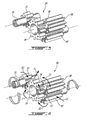
Fig. 1 is an isometric view, partly sectioned, of a high-speed gear pump in accordance with an embodiment of the present application; -
Fig. 2 is an isometric sectioned view of the high-speed gear pump ofFig. 1 , with gear rotational directions and fluid flow paths illustrated; -
Fig. 3 is an isometric view of a gear assembly of a two-stage high-speed gear pump in accordance with another embodiment of the present application; and -
Fig. 4 is an isometric view of the gear assembly of the two-stage high-speed gear pump ofFig. 3 , with gear rotational directions and a fluid flow illustrated. - Referring to
Fig. 1 , a high-speed gear pump is shown at 10, for pumping fluids such as oil and fuel. Thegear pump 10 has acasing 12 accommodating a gear assembly. To illustrate an interior of thegear pump 10, a portion of thecasing 12 is removed fromFigs. 1 and 2 . Thecasing 12 has afluid inlet 14 and afluid outlet 16. - The
gear pump 10 has aninput shaft 18 connected to a power source (not shown), such as a high-speed electric motor or the like. Adrive gear 20 is directly coupled to theinput shaft 18. Thedrive gear 20 is positioned adjacent to theoutlet 16 in thecasing 12. - A first driven
gear 21 and a second drivengear 22 are positioned adjacent to theinlet 14 in thecasing 12. The first drivengear 21 is meshed with thedrive gear 20, and is thereby driven by theinput shaft 18. The second drivengear 22 is meshed with the first drivengear 21, whereby the first drivengear 21 transmits actuation from thedrive gear 20 to the second drivengear 22. - The
drive gear 20 has a smaller number of teeth than the first drivengear 21 and the second drivengear 22. The drivengear Figs. 1 and 2 , thedrive gear 20 has eight teeth, while the drivengears gears drive gear 20, as the drivengear 21 acts as a speed-reduction gear in the gear assembly. - Referring to
Fig. 2 , a direction of rotation of thegears casing 12 from theinlet 14 to theoutlet 16. As illustrated by path A, a first portion of the fluid received by theinlet 14 is pressurized by passing between the first drivengear 21 and an interior of thecasing 12, to reach theoutlet 16. As illustrated by path B, a second portion of the fluid received by theinlet 14 is pressurized by passing between the second drivengear 22 and an interior of thecasing 12. The pressurized fluid illustrated by path B is then at least partially pressurized by passing between thedrive gear 20 and thecasing 12, as illustrated by path C. The pressure of the fluid at theoutlet 16 is therefore a mix of the pressures of the fluids coming from paths A and C. - As the pressure of the fluid is higher at the exit of path B than at the
inlet 14, thedrive gear 20 may rotate faster than if it were at theinlet 14, without causing cavitation. The arrangement by which the smaller and faster gear is at theoutlet 16 while the larger and slower gear is at theinlet 14 allows the use of a rotational input of higher speed without causing cavitation. - Moreover, in order to increase the pressure at the inlet to
gear 20, the leakage of fluid to path C may be controlled, to return some pressurized fluid to the outlet togear 22. The leakage is controlled by a direct path fromoutlet 16 by a cored line or by increasing the clearance between thegear 20 and the housing. By this leakage, the speed of thedrive gear 20 may be increased. - The second driven
gear 22 may be the only inlet gear, namely the only gear receiving fluid from theinlet 14. Other configurations are considered as well. - Referring to
Fig. 3 , a two-stage high-speed gear pump is illustrated at 30. For clarity purposes, thegear pump 30 is shown without a casing. Thegear pump 30 has aninput shaft 31 connected to a power source, such as a high-speed electric motor or the like.Drive gear 32 is coupled to theinput shaft 31. Outlet-stage drivengear 34 is meshed with thedrive gear 32, whereby rotational actuation of theinput shaft 31 is transmitted to the drivengear 34 through thedrive gear 32. Thedrive gear 32 has a smaller number of teeth than the drivengear 34, and therefore rotates faster than the drivengear 34. The drivengear 34 acts as a speed-reduction gear in the gear assembly. InFig. 3 , as an example, thedrive gear 32 has eight teeth, whereas the drivengear 34 has twelve teeth. - The outlet-stage driven
gear 34 has acoupling shaft 36 by which it is directly coupled to an inlet-stagefirst gear 38. The inlet-stagefirst gear 38 therefore rotates with the outlet-stage drivengear 34. - The inlet-stage
first gear 38 is meshed with an inlet-stagesecond gear 40. InFig. 3 , thefirst gear 38 and thesecond gear 40 of the inlet stage have the same number of teeth, namely eight teeth. Thefirst gear 38 and thesecond gear 40 may have a different number of teeth. - Referring to
Fig. 4 , a direction of rotation of thegears gear pump 30. - The inlet stage of the
gear pump 30 comprises thefirst gear 38 and thesecond gear 40. Accordingly, inlet fluid D is pressurized by passing through paths E1 or E2, respectively between the tips of thefirst gear 38 and an interior of the casing (not shown) and between the tips of thesecond gear 40 and an interior of the casing (not shown). The pressurized fluid from paths E1 and E2 then reaches the second stage, as illustrated by path F. - The outlet stage of the
gear pump 30 comprises thedrive gear 32 and the drivengear 34. The pressurized fluid from the path F is partly directly about thedrive gear 32 in path G1 and about the drivengear 34 in path G2, to respectively be pressurized between thedrive gear 32 and the casing (not shown), and the drivengear 34 and the casing (not shown). The outlet fluid H is therefore a mix of the pressurized fluid from paths G1 and G2. - In the
gear pump 30, the gear with the higher speed is thedrive gear 32. As it is at the outlet of thegear pump 30, thedrive gear 32 is fed pressurized fluid from the inlet stage, whereby it may rotate at higher speed without causing cavitation. By the gear reduction resulting from the gear arrangement of thegear pump 30, the first andsecond gears - Leakage may be controlled across the inlet stage and outlet stage. By limiting the leakage, the inlet pressure is increased, thereby enabling the gears of the
gear pump 30 to rotate faster. - As is shown in
Fig. 3 , thesecond gear 40 has a shaft. Other pump stages may be stacked to the two stages of thegear pump 30, in a multi-stage configuration. Thefirst gear 38 may be the only inlet gear, namely the only gear receiving fluid from the inlet, or the only gear in the first stage. Other configurations are considered as well. - In operating the gear pump 10 (
Figs. 1-2 ) and the gear pump 30 (Figs. 3-4 ), the tip velocity of thegears 21/22 and gears 38/40, respectively, may be controlled as a function of the measurement of the fluid inlet pressure, so as not to cause failure due to cavitation. By maintaining a higher inlet pressure, the gears may rotate faster. - The gear pump 10 (
Figs. 1-2 ) and the gear pump 30 (Figs. 3-4 ) may be used as fuel pumps. In such a use, the gear pumps 10 and 30 have a compact and simple design. Moreover, the gear pumps 10 and 30 are self-lubricating and may therefore be used in environments where auxiliary lubrication systems are not available. In turbine engine applications, the drive gears may be smaller when receiving a rotational input from the accessory gear box, thereby resulting in a compact gear pump. - Still other modifications will be apparent to those skilled in the art, in light of a review of this disclosure, and such modifications are intended to fall within the scope of the appended claims.
Claims (13)
- A gear pump (10;30) comprising:a casing (12) having an inlet (14) adapted to receive a fluid, an interior to receive gears to pressurize the fluid, and an outlet (16) to output pressurized fluid;at least one inlet gear (22;38) positioned at the inlet (14) and adapted to pressurize fluid received at the inlet (14);a drive gear (20;32) positioned at the outlet (16) of the casing (12), the drive gear (20;32) adapted to received fluid pressurized by the at least one inlet gear (22;38) to output pressurized fluid at the outlet;a speed-reduction gear (21;34) meshed to the drive gear (20;32) and connected to the at least one inlet gear (22;38), the speed-reduction gear (21;34) having a greater number of teeth than the drive gear (20;32) to reduce a rotational speed from the drive gear (20;32) to the at least one inlet gear (22;38), such that the at least one inlet gear (22;38) has a lower speed that the drive gear (20;32); andan input shaft (18;31) coupled to the drive gear (20;32) and adapted to receive a rotational input to actuate the drive gear (20;32).
- The gear pump according to claim 1, wherein the speed-reduction gear (21) is meshed with the inlet gear (22).
- The gear pump according to claim 2, wherein the speed-reduction gear (21) is placed at the inlet (14) concurrently with the inlet gear (22), the speed-reduction gear (21) being adapted to pressurize fluid received at the inlet (14), to output pressurized fluid to the outlet (16).
- The gear pump according to claim 2 or 3, wherein the speed-reduction gear (21) has a same number of teeth as the inlet gear (22).
- The gear pump according to claim 4, wherein the drive gear (20) has eight teeth, and the inlet gear (22) and speed-reduction gear (21) both have twelve teeth.
- The gear pump according to any preceding claim, further comprising means adapted to control a proportion of fluid supplied to the drive gear (20) versus a proportion of fluid returned to the inlet (16) after being pressurized by the inlet gear (22).
- The gear pump according to claim 1, further comprising at least a first stage and a second stage, the first stage comprising the inlet and the at least one inlet gear (38), the second stage comprising the drive gear (32), the speed-reduction gear (34) and the outlet, the first stage and the second stage being in fluid communication to be adapted to supply fluid from the first stage to the second stage.
- The gear pump according to claim 7, wherein the inlet gear (38) and the speed-reduction gear (34) are directly coupled by a common shaft (36).
- The gear pump according to claim 8, wherein the first stage has two of the inlet gear, with a first inlet gear (38) being directly coupled to the speed-reduction gear (34) by the common shaft (36), and a second inlet gear (40) being meshed with the first inlet gear (38).
- The gear pump according to claim 9, wherein the second inlet gear (40) has a shaft adapted to be coupled to another stage of the gear pump (30).
- The gear pump according to claim 9 or 10, wherein the first inlet gear (38) and the second inlet gear (40) have a same number of teeth.
- The gear pump according to claim 11, wherein the first inlet gear (38), the second inlet gear (40) and the drive gear (32) have eight teeth, and the speed-reduction gear (34) has twelve teeth.
- The gear pump according to any of claims 7 to 12, further comprising means adapted to control a proportion of fluid supplied from the first stage to the second stage versus a proportion of fluid returned to the inlet after being pressurized by the inlet gear (38).
Applications Claiming Priority (1)
| Application Number | Priority Date | Filing Date | Title |
|---|---|---|---|
| US12/252,641 US8292597B2 (en) | 2008-10-16 | 2008-10-16 | High-speed gear pump |
Publications (1)
| Publication Number | Publication Date |
|---|---|
| EP2177761A2 true EP2177761A2 (en) | 2010-04-21 |
Family
ID=41611103
Family Applications (1)
| Application Number | Title | Priority Date | Filing Date |
|---|---|---|---|
| EP09250764A Withdrawn EP2177761A2 (en) | 2008-10-16 | 2009-03-19 | High-speed gear pump |
Country Status (3)
| Country | Link |
|---|---|
| US (1) | US8292597B2 (en) |
| EP (1) | EP2177761A2 (en) |
| CA (1) | CA2665889C (en) |
Cited By (1)
| Publication number | Priority date | Publication date | Assignee | Title |
|---|---|---|---|---|
| WO2014082953A3 (en) * | 2012-11-30 | 2014-10-23 | Trw Automotive Gmbh | Pump unit, particularly for motor vehicles |
Families Citing this family (4)
| Publication number | Priority date | Publication date | Assignee | Title |
|---|---|---|---|---|
| US20080029173A1 (en) * | 2006-08-07 | 2008-02-07 | Diperna Paul Mario | Variable flow reshapable flow restrictor apparatus and related methods |
| JP5950583B2 (en) * | 2011-03-27 | 2016-07-13 | 株式会社山田製作所 | Pump device |
| DK177834B1 (en) * | 2013-02-27 | 2014-09-08 | C C Jensen As | Device for processing a liquid under vacuum pressure |
| CN110500275B (en) * | 2019-09-23 | 2021-03-16 | 兑通真空技术(上海)有限公司 | Pump housing structure of triaxial multistage roots pump |
Family Cites Families (40)
| Publication number | Priority date | Publication date | Assignee | Title |
|---|---|---|---|---|
| US1734779A (en) * | 1928-01-11 | 1929-11-05 | Diming Company | Pump |
| US2255851A (en) * | 1940-10-21 | 1941-09-16 | Radial Pump And Compressor Com | Pump assembly |
| US2354992A (en) * | 1941-11-11 | 1944-08-01 | Westinghouse Electric & Mfg Co | Gear pump |
| US2849863A (en) * | 1954-07-20 | 1958-09-02 | W M Welch Mfg Company | Hydraulic variable speed drive device |
| US3168043A (en) * | 1960-10-21 | 1965-02-02 | Reiners & Wiggermann Getriebe | Variable displacement pumps of the triple-gear type |
| US3120190A (en) * | 1961-03-02 | 1964-02-04 | Falk Corp | Gear pump |
| US3179382A (en) * | 1963-03-01 | 1965-04-20 | Norton Knedlik | Blending pump |
| US3179383A (en) * | 1963-03-01 | 1965-04-20 | Norton Knedlik | Method for metering and blending together a plurality of fluids |
| US3447422A (en) * | 1967-05-11 | 1969-06-03 | Moog Inc | Zero backlash fluid motor |
| US3427985A (en) * | 1967-08-09 | 1969-02-18 | Chandler Evans Inc | Three-gear pump with movable elements having plurality of sealing forces |
| US3481532A (en) * | 1967-12-20 | 1969-12-02 | Ingersoll Rand Co | Compressor |
| US3597131A (en) * | 1969-09-24 | 1971-08-03 | Chandler Evans Inc | Gear pump with travel limited tied wear block |
| US3627455A (en) | 1970-02-05 | 1971-12-14 | Trw Inc | Multicycle self-balancing gear pump |
| JPS5127281B2 (en) * | 1972-07-10 | 1976-08-12 | ||
| JPS5132783B2 (en) * | 1972-07-11 | 1976-09-14 | ||
| US4044562A (en) * | 1974-05-02 | 1977-08-30 | Will Clarke England | Multirotary energy conversion valve |
| US4032391A (en) * | 1975-09-03 | 1977-06-28 | Union Carbide Corporation | Low energy recovery compounding and fabricating systems for plastic materials |
| US4204811A (en) * | 1977-08-19 | 1980-05-27 | The Garrett Corporation | Fluid pumping system |
| US4475870A (en) * | 1980-08-19 | 1984-10-09 | Karl Eickmann | Hydraulic arrangement |
| US4597717A (en) * | 1982-09-30 | 1986-07-01 | Truline C.N.C., Inc. | Two-stage fluid pump |
| US4531494A (en) * | 1984-03-27 | 1985-07-30 | Caterpillar Tractor Co. | Distributor fuel injection pump having a nutator pump subassembly |
| US4815954A (en) * | 1984-11-26 | 1989-03-28 | Borg Warner Corporation | Offset three-gear, two-system pump |
| CN1009024B (en) * | 1986-09-24 | 1990-08-01 | 郑悦 | Axial variable pump or motor |
| US4824331A (en) * | 1987-07-29 | 1989-04-25 | Hydreco, Incorporated | Variable discharge gear pump with energy recovery |
| US4859158A (en) * | 1987-11-16 | 1989-08-22 | Weinbrecht John F | High ratio recirculating gas compressor |
| US4850813A (en) * | 1988-03-04 | 1989-07-25 | Ford Motor Company | Self unloading pump circuit for an automatic transmission having multiple pressure supply pumps |
| US5241826A (en) * | 1992-07-21 | 1993-09-07 | Stearns Charles F | Fixed geometry variable displacement pump system |
| KR100243893B1 (en) * | 1993-09-30 | 2000-03-02 | 다나까 도미오 | Gear pump |
| CA2159672C (en) | 1994-10-17 | 2009-09-15 | Siegfried A. Eisenmann | A valve train with suction-controlled ring gear/internal gear pump |
| CA2219062C (en) * | 1996-12-04 | 2001-12-25 | Siegfried A. Eisenmann | Infinitely variable ring gear pump |
| EP0931937A1 (en) * | 1998-01-22 | 1999-07-28 | Koyo Seiko Co., Ltd. | Speed control for hydraulic pump |
| US6327455B1 (en) * | 2000-01-26 | 2001-12-04 | Lexmark International, Inc. | Back-up roller with reduced mass |
| US6588207B1 (en) * | 2001-03-29 | 2003-07-08 | Alphonse A. Pouliot | Step-less, hydraulic power transmission |
| FR2828717A1 (en) * | 2001-08-16 | 2003-02-21 | Michelin Soc Tech | GEAR PUMP |
| US7841082B2 (en) * | 2002-05-06 | 2010-11-30 | Lurtz Jerome R | Non-eccentric devices |
| US6688498B1 (en) * | 2002-12-12 | 2004-02-10 | Illinois Tool Works Inc. | Hot melt adhesive supply system with independent gear pump assemblies |
| JP2006125391A (en) * | 2004-09-28 | 2006-05-18 | Aisin Seiki Co Ltd | Rotor structure of internal gear type pump |
| JP4084351B2 (en) * | 2004-12-24 | 2008-04-30 | 株式会社日立製作所 | Motor-integrated internal gear pump and electronic equipment |
| US7465158B2 (en) * | 2006-04-04 | 2008-12-16 | Bevan Weston | Reduction gear pump |
| US20080056912A1 (en) * | 2006-08-31 | 2008-03-06 | Pizzichil William P | Pump system and method using planetary gear assembly |
-
2008
- 2008-10-16 US US12/252,641 patent/US8292597B2/en active Active
-
2009
- 2009-03-19 EP EP09250764A patent/EP2177761A2/en not_active Withdrawn
- 2009-05-12 CA CA2665889A patent/CA2665889C/en not_active Expired - Fee Related
Cited By (1)
| Publication number | Priority date | Publication date | Assignee | Title |
|---|---|---|---|---|
| WO2014082953A3 (en) * | 2012-11-30 | 2014-10-23 | Trw Automotive Gmbh | Pump unit, particularly for motor vehicles |
Also Published As
| Publication number | Publication date |
|---|---|
| CA2665889C (en) | 2011-10-11 |
| CA2665889A1 (en) | 2010-04-16 |
| US8292597B2 (en) | 2012-10-23 |
| US20100098572A1 (en) | 2010-04-22 |
Similar Documents
| Publication | Publication Date | Title |
|---|---|---|
| US7707909B2 (en) | Device for driving accessory machines of a gas turbine engine | |
| US8640452B2 (en) | Hydraulic circuit for a power transmission device | |
| CA2665889C (en) | High-speed gear pump | |
| CN100554664C (en) | Twin-shaft turbine engine, its power take-off module and method of assembling the engine | |
| KR101601072B1 (en) | Oil pump for automatic transmission | |
| JP5983419B2 (en) | Fuel system | |
| EP1900973A1 (en) | Transmission system for pump drive | |
| US20120308362A1 (en) | Dual input drive agb for gas turbine engines | |
| JP2019533108A (en) | Dual input pump and system | |
| CN103225548B (en) | For the bevel gear arrangements structure of axial Accessory Gear Box | |
| US9371000B2 (en) | Transmission having integrated transmission pump and accessory drive | |
| US8127748B2 (en) | Fuel pumping system | |
| US9546728B2 (en) | Balanced binary pump for CVT transmission | |
| EP2042737B1 (en) | Pressure recovery system | |
| WO2012020568A1 (en) | Engine system and ship | |
| US8596991B2 (en) | Thermally efficient multiple stage gear pump | |
| SE519200C2 (en) | Gas turbine device with an arrangement for operating one or more auxiliary appliances | |
| US11506199B2 (en) | Pump assembly with pump chambers located radially relative to one another and connected serially | |
| US7982323B2 (en) | Electrical generator | |
| US20150086393A1 (en) | Oil pump for vehicle | |
| US20250101978A1 (en) | Tandem pump comprising a main flow and a dry sump flow | |
| CN112334657A (en) | Pump and gear device with pump | |
| KR20010078863A (en) | Cylindrical Spiral Screw Propeller Propeller | |
| KR100281573B1 (en) | Transmission | |
| JPH07167065A (en) | Liquid pump drive |
Legal Events
| Date | Code | Title | Description |
|---|---|---|---|
| PUAI | Public reference made under article 153(3) epc to a published international application that has entered the european phase |
Free format text: ORIGINAL CODE: 0009012 |
|
| AK | Designated contracting states |
Kind code of ref document: A2 Designated state(s): AT BE BG CH CY CZ DE DK EE ES FI FR GB GR HR HU IE IS IT LI LT LU LV MC MK MT NL NO PL PT RO SE SI SK TR |
|
| AX | Request for extension of the european patent |
Extension state: AL BA RS |
|
| STAA | Information on the status of an ep patent application or granted ep patent |
Free format text: STATUS: THE APPLICATION HAS BEEN WITHDRAWN |
|
| 18W | Application withdrawn |
Effective date: 20130228 |