EP2177722A2 - Valve housing attachable to a vehicle cooling module, vehicle cooling module and combinaison thereof - Google Patents
Valve housing attachable to a vehicle cooling module, vehicle cooling module and combinaison thereof Download PDFInfo
- Publication number
- EP2177722A2 EP2177722A2 EP09172171A EP09172171A EP2177722A2 EP 2177722 A2 EP2177722 A2 EP 2177722A2 EP 09172171 A EP09172171 A EP 09172171A EP 09172171 A EP09172171 A EP 09172171A EP 2177722 A2 EP2177722 A2 EP 2177722A2
- Authority
- EP
- European Patent Office
- Prior art keywords
- cooling module
- valve housing
- vehicle cooling
- attachment member
- interlocking attachment
- Prior art date
- Legal status (The legal status is an assumption and is not a legal conclusion. Google has not performed a legal analysis and makes no representation as to the accuracy of the status listed.)
- Granted
Links
Images


Classifications
-
- F—MECHANICAL ENGINEERING; LIGHTING; HEATING; WEAPONS; BLASTING
- F01—MACHINES OR ENGINES IN GENERAL; ENGINE PLANTS IN GENERAL; STEAM ENGINES
- F01P—COOLING OF MACHINES OR ENGINES IN GENERAL; COOLING OF INTERNAL-COMBUSTION ENGINES
- F01P11/00—Component parts, details, or accessories not provided for in, or of interest apart from, groups F01P1/00 - F01P9/00
- F01P11/08—Arrangements of lubricant coolers
-
- F—MECHANICAL ENGINEERING; LIGHTING; HEATING; WEAPONS; BLASTING
- F01—MACHINES OR ENGINES IN GENERAL; ENGINE PLANTS IN GENERAL; STEAM ENGINES
- F01M—LUBRICATING OF MACHINES OR ENGINES IN GENERAL; LUBRICATING INTERNAL COMBUSTION ENGINES; CRANKCASE VENTILATING
- F01M5/00—Heating, cooling, or controlling temperature of lubricant; Lubrication means facilitating engine starting
- F01M5/002—Cooling
-
- F—MECHANICAL ENGINEERING; LIGHTING; HEATING; WEAPONS; BLASTING
- F01—MACHINES OR ENGINES IN GENERAL; ENGINE PLANTS IN GENERAL; STEAM ENGINES
- F01M—LUBRICATING OF MACHINES OR ENGINES IN GENERAL; LUBRICATING INTERNAL COMBUSTION ENGINES; CRANKCASE VENTILATING
- F01M5/00—Heating, cooling, or controlling temperature of lubricant; Lubrication means facilitating engine starting
- F01M5/005—Controlling temperature of lubricant
- F01M5/007—Thermostatic control
Definitions
- the invention relates to a valve housing which is attachable to a vehicle cooling module.
- the invention further relates to a vehicle cooling module and a combination thereof.
- a vehicle cooling module may be realized as a stacked plate heat exchanger. Fluids to be cooled in a vehicle comprise for example the transmission oil.
- a stacked plate heat exchanger has flow channels for the oil to be cooled as well as flow channels for a coolant used to cool the oil.
- the oil is not only cooled but it may need to be warmed up in the start phase of a vehicle. The temperature of the oil is thus not only cooled but it is regulated to be maintained in a specified temperature range.
- the temperature of the oil is sensed and the flow of the coolant is controlled according to the temperature detected.
- a valve unit comprising a thermostatic operating element which is arranged in the oil flow of the heat exchanger.
- a work piston of the thermostatic operating element actuates one or more valves controlling the flow of the coolant.
- the valve unit is accommodated in a valve housing which is attached to the vehicle heat exchanger or vehicle cooling module.
- the valve housing must be adapted to the vehicle cooling module in such a way that the temperature measuring element has access to the fluid the temperature of which is to be regulated, while the valve which is controlled by the thermostatic element is in the coolant flow.
- coolant ports and oil ports of heat exchangers are usually situated in different corners or at different sides of the heat exchanger so that the valve housing must be large enough to cover both ports and must comprise an oil or coolant channel.
- valve housings are attached with a number of screws, i.e. six or more screws are usually used. Attaching the valve housing to the cooling module by screws is time consuming and leads to high work costs. Additionally with a high copper price the needed brass screws are also expensive. Because of the high pressure of the oil inside the heat exchanger, which can be as high as 20 bar, the attachment must be of high strength.
- valve housing for accommodating a valve unit which can be attached to a vehicle cooling module in a faster and less expensive way without compromising the tightness of the seal.
- the invention provides a valve housing attachable to a vehicle cooling module with the features according to claim 1.
- the valve housing comprises a connection surface with an oil channel port for fluidic connection to an oil channel of the vehicle cooling module and a cooling channel port for fluidic connection to a coolant channel of the vehicle cooling module when the valve housing is attached.
- the valve housing further comprises at least one first interlocking attachment member which is adapted to engage a second interlocking attachment member provided on the vehicle cooling module to provide a clamping connection between the valve housing and the vehicle cooling module.
- the first and second interlocking attachment members are adapted to let the connection surface of the valve housing move into contact with the vehicle cooling module.
- the stacked plate oil cooler has an oil inlet and the coolant outlet on the same side of the oil cooler.
- the distance between oil inlet and coolant outlet is as small as 32 mm,
- the at least one first interlocking attachment member is preferably provided for the coolant side, i.e. near the coolant outlet from the oil cooler.
- the first and second interlocking members define a pivot axis and are adapted to interact to clamp the valve housing and the vehicle cooling module together by a swiveling movement of the valve housing relative to the vehicle cooling module.
- the first interlocking member must only engage the second interlocking member and then the valve housing is simply turned around the pivot axis into its assembled position, housing and module being automatically clamped together. Assembly is finished by one or two screws.
- first interlocking attachment members are provided on opposite sides of the valve housing, so that only one screw is necessary for securely attaching the valve housing to the heat exchanger.
- first interlocking attachment member is a protrusion which is insertable into a second interlocking attachment member provided on the vehicle cooling module.
- the protrusion has a cross section with a first dimension in a direction basically perpendicular to the connection surface and a second dimension which is greater than the first dimension in a direction basically parallel to the connection surface.
- the second interlocking attachment member of the vehicle cooling module is provided with an aperture having a dimension between the first dimension value and the second dimension value, insertion of the first interlocking attachment member is possible when oriented in a first direction, and the first interlocking attachment member is locked when the first interlocking attachment member is turned into a second direction.
- the protrusion is provided with at least one guiding surface.
- the vehicle cooling module has preferably a second interlocking attachment member which is provided with a guiding ramp which is adapted to cooperate with the guiding surface of the protrusion.
- the clamping connection as described necessitates a swiveling movement in the assembly phase.
- the first interlocking attachment member is preferably formed near one end surface of the housing, and an edge of the one end surface of the housing which is directed to the vehicle cooling module is rounded.
- the valve housing is adapted to be turned along the rounded edge when mounted onto the vehicle cooling module, and the rounded edge is provided with at least two beads which extend in a direction basically perpendicular to the edge.
- the rounded edge controls the distance between the connection surface and a counter surface of the vehicle cooling module during assembly thus assuring that the sealing means are not displaced or pressed irregularly.
- the invention further provides a vehicle cooling module with the features according to claim 14.
- the vehicle cooling module comprises at least one second interlocking attachment member which is adapted to engage a first interlocking attachment member of a valve housing and to interact with the first interlocking attachment member to clamp the vehicle cooling module and the valve housing together.
- the at least one second interlocking attachment member is arranged at a cover of the vehicle cooling module.
- the cover is formed integrally with the second interlocking attachment member out of a metal, which could be for example aluminum.
- the invention relates to a combination of a valve housing and a vehicle cooling module as claimed.
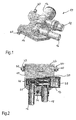
- Fig. 1 shows a valve housing 10 according to a preferred embodiment of the invention.
- the valve housing 10 comprises a first part 12 formed to accommodate a valve unit and a second, flange-like part 14 for attaching the valve housing 10 to a vehicle cooling module which is not shown in Fig. 1 .
- the valve unit is adapted to measure the temperature of a first fluid, the temperature of which is to be regulated, and to control a flow rate of a second fluid which is used to cool down or heat up the first fluid depending on the temperature measured.
- the valve housing 10 further comprises a first connecting pipe 16 for the first fluid and a second connecting pipe 18 for the second fluid.
- first connecting pipe 16 is an oil inlet for a transmission oil of a vehicle
- connecting pipe 18 is a coolant outlet from the vehicle cooling module which is in the preferred embodiment an oil cooler.
- Connecting pipe 16 could also be an oil outlet and connecting pipe 18 a coolant inlet.
- other kinds of fluids are possible in other applications.
- valve housing 10 has in the preferred embodiment a thickness of about 10 mm.
- Valve housing 10 is provided with two first interlocking attachment members 20 formed as protrusions.
- Fig. 2 shows the valve housing 10 from the upper side with part 12, which accommodates the valve unit, cut through. Thus, the regulating valve unit is visible.
- the valve housing 10 is mounted to a vehicle cooling module 22 of which only a small part is shown.
- the oil which flows into the connecting pipe 16 passes a thermostatic operation element 24 which is adapted to sense the oil temperature.
- the oil then passes through an oil port 26 into the vehicle cooling module 22 which is preferably a stacked plate heat exchanger.
- a work piston of the thermostatic operating element 24 is connected to a valve 28 which controls the flow rate of the coolant which enters the valve housing by a coolant channel port 30 from vehicle cooling module 22, passes the valve 28 and then passes through connecting pipe 18.
- Oil channel port 26 and coolant channel port 30 are realized as openings, preferably as holes in the flange-like part 14 of the valve housing.
- the distance between oil channel port 26 and coolant channel port 30 is about 32 mm.
- a distance comprised between 30 and 35 mm is preferred, as this allows a small valve housing 10.
- corresponding openings are provided in vehicle cooling module 22 or more precisely in cover 21 giving access to the oil and coolant channel of the cooling module 22.
- Sealing means are provided around the oil channel port 26 and the coolant channel port 30 between valve housing 10 and vehicle cooling module 22.
- First interlocking attachment members 20 are inserted into second interlocking attachment members 32 of the vehicle cooling module 22.
- a screw 33 further attaches the valve housing 10 to the vehicle cooling module 22 near the two connecting pipes.
- Fig. 3 shows the valve housing 10 attached to the vehicle cooling module 22.
- Vehicle cooling module 22 is shown schematically. Vehicle cooling module 22 is in the preferred embodiment closed by a cover 21. Cover 21 is preferably made out of metal and soldered to vehicle cooling module 22.
- the vehicle cooling module 22 has an oil inlet next to a coolant outlet with a distance of about 32 mm.
- the valve housing 10 which must have an access to the oil circulating in the vehicle cooling module 22 for the thermostatic operating element of the valve unit and which must have an access to the coolant circulating in the vehicle cooling module 22 for regulating its flow, can be very small in relation to the cooling module.
- Three fixation points, i.e. first interlocking attachment members 20 together with second interlocking attachment members 32 and screw 33, between valve housing 10 and vehicle cooling module 22 are sufficient for attaching securely the valve housing. It should be understood that the fluids are under pressure with the oil pressure going up to 20 bars.
- Fig. 4 shows valve housing 10 and vehicle cooling module 22 from another side.
- Two connection pipes 35 and 37 are provided for vehicle cooling module 22 forming an oil outlet from the cooling module 22 and a coolant inlet, respectively.
- Second interlocking attachment members 32 are attached to cover 21 or formed in one piece with cover 21.
- FIG. 5 shows in a side view part of vehicle cooling module 22 with second interlocking attachment member 32 as well as valve housing 10 with flange-like part 14, the valve unit accommodating part 12 and first interlocking attachment member 20.
- the first interlocking attachment member 20 is a protrusion or pin projecting form flange-like part 14 of valve housing 10.
- the flange-like part 14 has a connection surface 34 which in the mounted position is next to a counter surface of the vehicle cooling module 22 with cover 21.
- First interlocking attachment member or protrusion 20 has a cross section with a first dimension between a face A and a face B in a direction basically perpendicular to the connection surface and a second dimension between a face C and a face D in a direction basically parallel to the connection surface. As is clearly visible in Fig. 5 , the first dimension is smaller than the second dimension.
- block-like shaped interlocking attachment member 32 has an aperture which allows insertion of protrusion 20 when oriented in a way that it passes the aperture with the first dimension AB.
- the aperture of second interlocking attachment member 32 is only slightly greater than the first dimension AB and smaller than the second dimension CD.
- first interlocking attachment member 20 To facilitate insertion of first interlocking attachment member 20 it is provided with two guiding surfaces 36. During the assembly phase as shown in Fig. 5 , the guiding surfaces 36 glide along a guiding ramp 38 of second interlocking attachment member 32.
- First interlocking attachment member 20 is inserted into second interlocking attachment member 32 by moving valve housing 10 in a direction defined by an angle of about 45° between connection surface 34 of valve housing 10 and the counter surface of vehicle cooling module 22, i.e. in the embodiment shown a surface of cover 21. Angles between 25° and 90° are possible depending on the exact form of the interlocking attachment members 20, 32. A too small angle increases the risk to displace the sealing rings necessary between valve housing 10 and vehicle cooling module 22.
- first interlocking attachment member 20 is inserted into the second interlocking attachment member 32, the valve housing 10 is turned around a pivot axis defined by first and second interlocking attachment members 20, 32 in a swiveling movement until flange-like part 14 contacts with its connection surface 34 a counter surface of cooling vehicle module 22 which is formed by a surface of cover 21.
- the first and second interlocking attachment members 20, 32 interact to let the connection surface 34 move into contact with the vehicle cooling module.
- a locking surface 40 on the first interlocking attachment member 20 is in contact with a securing surface 42 of second interlocking attachment member 32. Assembly is finished by screwing screw 33.
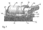
- valve housing 10 In the swiveling movement during attachment valve housing 10 will turn around the pivot axis defined by first and second interlocking attachment members and valve housing 10 will glide with its rounded edge 44 on vehicle cooling module 22.
- the rounded edge 44 is preferably provided with two beads 46. The two beads extend in a direction basically perpendicular to the edge 44. Thus, valve housing 10 will glide on the two beads 46 which contact an upper surface of cover 21.
- a further measure to have the seals not displaced during swiveling is to arrange the pivot axis distanced from the seal and at an edge of part 14.
- valve housing 10 is preferably a molded plastic part and thus very easy to manufacture.
- Suitable plastic materials comprise PPS (polyvinylenesulfide), PPA (polyphthalamide) and PA6.6 (polyamide).
- the form of first interlocking attachment members 20 can slightly differ from the form shown for the preferred embodiment for taking into account the molding characteristics of the plastic material and the strength of the material.
- Second interlocking attachment member 32 is preferably integral to cover 21 of vehicle cooling module 22.
- cover and receiving parts are a stamping part out of aluminum with the receiving parts bent into the desired position as shown in the figures.
- Cover 21 with second interlocking attachment member 32 may also be cut out by a laser beam.
- first interlocking attachment members Although two first interlocking attachment members are shown for the preferred embodiment, it should be clear that a valve housing 10 with only one first interlocking attachment member is also covered by the invention. It is possible, that depending on the material used and the pressure present in the fluid channels, a connection as described using first and second interlocking attachment members may only be possible for example on the coolant side, i.e. the side of connecting pipe 18, where the pressure is less important. In this case, the oil side near connecting pipe 16 must still be fixed by a screw.
- first and second interlocking attachment members can be adapted to different housing forms.
- the number of first and second interlocking attachment members may also vary.
Landscapes
- Engineering & Computer Science (AREA)
- Chemical & Material Sciences (AREA)
- Combustion & Propulsion (AREA)
- Mechanical Engineering (AREA)
- General Engineering & Computer Science (AREA)
- Cooling, Air Intake And Gas Exhaust, And Fuel Tank Arrangements In Propulsion Units (AREA)
- Temperature-Responsive Valves (AREA)
- Valve Housings (AREA)
- Quick-Acting Or Multi-Walled Pipe Joints (AREA)
Abstract
Description
- The invention relates to a valve housing which is attachable to a vehicle cooling module. The invention further relates to a vehicle cooling module and a combination thereof.
- All kind of vehicles, for example automotives, cars and trucks comprise cooling components for a cooling system. A vehicle cooling module may be realized as a stacked plate heat exchanger. Fluids to be cooled in a vehicle comprise for example the transmission oil. A stacked plate heat exchanger has flow channels for the oil to be cooled as well as flow channels for a coolant used to cool the oil. Depending on the application in which the heat exchanger is used, the oil is not only cooled but it may need to be warmed up in the start phase of a vehicle. The temperature of the oil is thus not only cooled but it is regulated to be maintained in a specified temperature range.
- For regulating the temperature, the temperature of the oil is sensed and the flow of the coolant is controlled according to the temperature detected. It is well-known in the state of the art to provide the heat exchanger with a valve unit comprising a thermostatic operating element which is arranged in the oil flow of the heat exchanger. A work piston of the thermostatic operating element actuates one or more valves controlling the flow of the coolant. The valve unit is accommodated in a valve housing which is attached to the vehicle heat exchanger or vehicle cooling module. The valve housing must be adapted to the vehicle cooling module in such a way that the temperature measuring element has access to the fluid the temperature of which is to be regulated, while the valve which is controlled by the thermostatic element is in the coolant flow. In the state of the art coolant ports and oil ports of heat exchangers are usually situated in different corners or at different sides of the heat exchanger so that the valve housing must be large enough to cover both ports and must comprise an oil or coolant channel.
- Of course, the fluidic connection must be leak proved, therefore a sealing is provided between the vehicle cooling module and the valve housing and the fixation of the valve housing to the heat exchanger must assure a sufficient pressure on the sealing. Thus, in the state of the art the valve housings are attached with a number of screws, i.e. six or more screws are usually used. Attaching the valve housing to the cooling module by screws is time consuming and leads to high work costs. Additionally with a high copper price the needed brass screws are also expensive. Because of the high pressure of the oil inside the heat exchanger, which can be as high as 20 bar, the attachment must be of high strength.
- There is a need for a valve housing for accommodating a valve unit which can be attached to a vehicle cooling module in a faster and less expensive way without compromising the tightness of the seal.
- The invention provides a valve housing attachable to a vehicle cooling module with the features according to claim 1. The valve housing comprises a connection surface with an oil channel port for fluidic connection to an oil channel of the vehicle cooling module and a cooling channel port for fluidic connection to a coolant channel of the vehicle cooling module when the valve housing is attached. The valve housing further comprises at least one first interlocking attachment member which is adapted to engage a second interlocking attachment member provided on the vehicle cooling module to provide a clamping connection between the valve housing and the vehicle cooling module. The first and second interlocking attachment members are adapted to let the connection surface of the valve housing move into contact with the vehicle cooling module. The stacked plate oil cooler has an oil inlet and the coolant outlet on the same side of the oil cooler. The distance between oil inlet and coolant outlet is as small as 32 mm, Thus, in addition to the first interlocking attachment member providing a clamp connection only one or two screwing points are necessary to complete fixation of the valve housing on the module. Of course with other cooling modules and another housing form, more screwing points may still be needed. The at least one first interlocking attachment member is preferably provided for the coolant side, i.e. near the coolant outlet from the oil cooler.
- Preferably, the first and second interlocking members define a pivot axis and are adapted to interact to clamp the valve housing and the vehicle cooling module together by a swiveling movement of the valve housing relative to the vehicle cooling module. Thus, the first interlocking member must only engage the second interlocking member and then the valve housing is simply turned around the pivot axis into its assembled position, housing and module being automatically clamped together. Assembly is finished by one or two screws.
- In a preferred embodiment, two first interlocking attachment members are provided on opposite sides of the valve housing, so that only one screw is necessary for securely attaching the valve housing to the heat exchanger. In a preferred embodiment the first interlocking attachment member is a protrusion which is insertable into a second interlocking attachment member provided on the vehicle cooling module.
- Preferably, the protrusion has a cross section with a first dimension in a direction basically perpendicular to the connection surface and a second dimension which is greater than the first dimension in a direction basically parallel to the connection surface. Thus, when the second interlocking attachment member of the vehicle cooling module is provided with an aperture having a dimension between the first dimension value and the second dimension value, insertion of the first interlocking attachment member is possible when oriented in a first direction, and the first interlocking attachment member is locked when the first interlocking attachment member is turned into a second direction.
- For facilitating insertion of a first interlocking attachment member into the second interlocking attachment member and thus further reducing the assembly time, the protrusion is provided with at least one guiding surface. In this case the vehicle cooling module has preferably a second interlocking attachment member which is provided with a guiding ramp which is adapted to cooperate with the guiding surface of the protrusion.
- The clamping connection as described necessitates a swiveling movement in the assembly phase. During the swiveling movement it must be assured, that the sealing between the valve housing and the cooling module is not displaced. Therefore, the first interlocking attachment member is preferably formed near one end surface of the housing, and an edge of the one end surface of the housing which is directed to the vehicle cooling module is rounded.
- In a preferred embodiment, the valve housing is adapted to be turned along the rounded edge when mounted onto the vehicle cooling module, and the rounded edge is provided with at least two beads which extend in a direction basically perpendicular to the edge. Thus, during the swiveling movement, only the two beads are in direct contact with the surface of the cooling module thus decreasing the frictional forces between the valve housing and the cooling module during assembly. The rounded edge controls the distance between the connection surface and a counter surface of the vehicle cooling module during assembly thus assuring that the sealing means are not displaced or pressed irregularly.
- The invention further provides a vehicle cooling module with the features according to
claim 14. The vehicle cooling module comprises at least one second interlocking attachment member which is adapted to engage a first interlocking attachment member of a valve housing and to interact with the first interlocking attachment member to clamp the vehicle cooling module and the valve housing together. - In a preferred embodiment, the at least one second interlocking attachment member is arranged at a cover of the vehicle cooling module. Advantageously, the cover is formed integrally with the second interlocking attachment member out of a metal, which could be for example aluminum.
- Finally, the invention relates to a combination of a valve housing and a vehicle cooling module as claimed.
- Further details and advantages of the invention will ensue from the following description of a preferred embodiment with reference to the accompanying drawings in which:
-
Fig. 1 shows in a three-dimensional view a valve housing according to the invention; -
Fig. 2 shows the valve housing seen from above with part of the valve housing cut away; -
Fig. 3 shows in a three-dimensional view the valve housing attached to a vehicle cooling module; -
Fig. 4 shows in a three-dimensional view the valve housing attached to the vehicle cooling module seen from another side; -
Fig. 5 shows in a side view a valve housing during attachment to the vehicle cooling module; -
Fig. 6 shows a detail of the valve housing attached to the vehicle cooling module in a side view showing the first and second attachment members; and -
Fig. 7 shows in a three-dimensional view the valve housing attached to the vehicle cooling module showing the rounded edge of the valve housing. -
Fig. 1 shows avalve housing 10 according to a preferred embodiment of the invention. Thevalve housing 10 comprises afirst part 12 formed to accommodate a valve unit and a second, flange-like part 14 for attaching thevalve housing 10 to a vehicle cooling module which is not shown inFig. 1 . The valve unit is adapted to measure the temperature of a first fluid, the temperature of which is to be regulated, and to control a flow rate of a second fluid which is used to cool down or heat up the first fluid depending on the temperature measured. Thevalve housing 10 further comprises a first connectingpipe 16 for the first fluid and a second connectingpipe 18 for the second fluid. - In the preferred embodiment, the first connecting
pipe 16 is an oil inlet for a transmission oil of a vehicle, and connectingpipe 18 is a coolant outlet from the vehicle cooling module which is in the preferred embodiment an oil cooler. Connectingpipe 16 could also be an oil outlet and connecting pipe 18 a coolant inlet. Of course, other kinds of fluids are possible in other applications. - The flange-
like part 14 ofvalve housing 10 has in the preferred embodiment a thickness of about 10 mm. Valvehousing 10 is provided with two first interlockingattachment members 20 formed as protrusions. -
Fig. 2 shows thevalve housing 10 from the upper side withpart 12, which accommodates the valve unit, cut through. Thus, the regulating valve unit is visible. Thevalve housing 10 is mounted to avehicle cooling module 22 of which only a small part is shown. The oil which flows into the connectingpipe 16 passes athermostatic operation element 24 which is adapted to sense the oil temperature. The oil then passes through anoil port 26 into thevehicle cooling module 22 which is preferably a stacked plate heat exchanger. A work piston of thethermostatic operating element 24 is connected to avalve 28 which controls the flow rate of the coolant which enters the valve housing by acoolant channel port 30 fromvehicle cooling module 22, passes thevalve 28 and then passes through connectingpipe 18.Oil channel port 26 andcoolant channel port 30 are realized as openings, preferably as holes in the flange-like part 14 of the valve housing. The distance betweenoil channel port 26 andcoolant channel port 30 is about 32 mm. A distance comprised between 30 and 35 mm is preferred, as this allows asmall valve housing 10. Of course, corresponding openings are provided invehicle cooling module 22 or more precisely incover 21 giving access to the oil and coolant channel of thecooling module 22. Thus, there is a fluidic connection to an oil channel ofvehicle cooling module 22 and to a coolant channel ofvehicle cooling module 22, respectively. - Sealing means are provided around the
oil channel port 26 and thecoolant channel port 30 betweenvalve housing 10 andvehicle cooling module 22. - First interlocking
attachment members 20 are inserted into secondinterlocking attachment members 32 of thevehicle cooling module 22. A screw 33 further attaches thevalve housing 10 to thevehicle cooling module 22 near the two connecting pipes. -
Fig. 3 shows thevalve housing 10 attached to thevehicle cooling module 22.Vehicle cooling module 22 is shown schematically.Vehicle cooling module 22 is in the preferred embodiment closed by acover 21.Cover 21 is preferably made out of metal and soldered tovehicle cooling module 22. Thevehicle cooling module 22 has an oil inlet next to a coolant outlet with a distance of about 32 mm. Thus, thevalve housing 10 which must have an access to the oil circulating in thevehicle cooling module 22 for the thermostatic operating element of the valve unit and which must have an access to the coolant circulating in thevehicle cooling module 22 for regulating its flow, can be very small in relation to the cooling module. Three fixation points, i.e. first interlockingattachment members 20 together with secondinterlocking attachment members 32 and screw 33, betweenvalve housing 10 andvehicle cooling module 22 are sufficient for attaching securely the valve housing. It should be understood that the fluids are under pressure with the oil pressure going up to 20 bars. -
Fig. 4 showsvalve housing 10 andvehicle cooling module 22 from another side. Two connection pipes 35 and 37 are provided forvehicle cooling module 22 forming an oil outlet from thecooling module 22 and a coolant inlet, respectively. Secondinterlocking attachment members 32 are attached to cover 21 or formed in one piece withcover 21. - Now interaction of first interlocking
attachment member 20 ofvalve housing 10 and secondinterlocking attachment member 32 ofvehicle cooling module 22 will be explained in more detail with reference toFigs. 5 and 6. Fig. 5 shows in a side view part ofvehicle cooling module 22 with secondinterlocking attachment member 32 as well asvalve housing 10 with flange-like part 14, the valveunit accommodating part 12 and firstinterlocking attachment member 20. - The first
interlocking attachment member 20 is a protrusion or pin projecting form flange-like part 14 ofvalve housing 10. The flange-like part 14 has aconnection surface 34 which in the mounted position is next to a counter surface of thevehicle cooling module 22 withcover 21. First interlocking attachment member orprotrusion 20 has a cross section with a first dimension between a face A and a face B in a direction basically perpendicular to the connection surface and a second dimension between a face C and a face D in a direction basically parallel to the connection surface. As is clearly visible inFig. 5 , the first dimension is smaller than the second dimension. - Second, block-like shaped interlocking
attachment member 32 has an aperture which allows insertion ofprotrusion 20 when oriented in a way that it passes the aperture with the first dimension AB. The aperture of secondinterlocking attachment member 32 is only slightly greater than the first dimension AB and smaller than the second dimension CD. - To facilitate insertion of first interlocking
attachment member 20 it is provided with two guidingsurfaces 36. During the assembly phase as shown inFig. 5 , the guiding surfaces 36 glide along a guidingramp 38 of secondinterlocking attachment member 32. First interlockingattachment member 20 is inserted into secondinterlocking attachment member 32 by movingvalve housing 10 in a direction defined by an angle of about 45° betweenconnection surface 34 ofvalve housing 10 and the counter surface ofvehicle cooling module 22, i.e. in the embodiment shown a surface ofcover 21. Angles between 25° and 90° are possible depending on the exact form of the interlockingattachment members valve housing 10 andvehicle cooling module 22. - Once first interlocking
attachment member 20 is inserted into the secondinterlocking attachment member 32, thevalve housing 10 is turned around a pivot axis defined by first and secondinterlocking attachment members like part 14 contacts with its connection surface 34 a counter surface of coolingvehicle module 22 which is formed by a surface ofcover 21. Thus, the first and secondinterlocking attachment members connection surface 34 move into contact with the vehicle cooling module. In this position a lockingsurface 40 on the firstinterlocking attachment member 20 is in contact with a securingsurface 42 of secondinterlocking attachment member 32. Assembly is finished by screwing screw 33. - As already explained, there is a fluidic connection between the
oil channel port 26 ofvalve housing 10 to an oil channel ofvehicle cooling module 22 and a fluidic connection between thecoolant channel port 30 ofvalve housing 10 and a coolant channel in thevehicle cooling module 22. As well-known in the state of the art, a sealing is necessary between the two interfaces. The sealing is usually provided by sealing rings. It is important to make sure that the swiveling movement will not displace the sealing rings and/or unequally press the sealing rings. Therefore, at one end surface of flange-like part 14 which is next to the firstinterlocking attachment members 20 an edge to the connection surface is rounded. Therounded edge 44 is shown inFig. 7 . In the swiveling movement duringattachment valve housing 10 will turn around the pivot axis defined by first and second interlocking attachment members andvalve housing 10 will glide with itsrounded edge 44 onvehicle cooling module 22. In order to minimize frictional forces while turningvalve housing 10, therounded edge 44 is preferably provided with twobeads 46. The two beads extend in a direction basically perpendicular to theedge 44. Thus,valve housing 10 will glide on the twobeads 46 which contact an upper surface ofcover 21. - A further measure to have the seals not displaced during swiveling is to arrange the pivot axis distanced from the seal and at an edge of
part 14. - As to the materials used,
valve housing 10 is preferably a molded plastic part and thus very easy to manufacture. Suitable plastic materials comprise PPS (polyvinylenesulfide), PPA (polyphthalamide) and PA6.6 (polyamide). Depending on the material used, the form of first interlockingattachment members 20 can slightly differ from the form shown for the preferred embodiment for taking into account the molding characteristics of the plastic material and the strength of the material. - Second
interlocking attachment member 32 is preferably integral to cover 21 ofvehicle cooling module 22. In a preferred embodiment, cover and receiving parts are a stamping part out of aluminum with the receiving parts bent into the desired position as shown in the figures.Cover 21 with secondinterlocking attachment member 32 may also be cut out by a laser beam. - Although two first interlocking attachment members are shown for the preferred embodiment, it should be clear that a
valve housing 10 with only one first interlocking attachment member is also covered by the invention. It is possible, that depending on the material used and the pressure present in the fluid channels, a connection as described using first and second interlocking attachment members may only be possible for example on the coolant side, i.e. the side of connectingpipe 18, where the pressure is less important. In this case, the oil side near connectingpipe 16 must still be fixed by a screw. - The combination of the
vehicle cooling module 22 with thevalve housing 10 can be assembled in a shorter time and requires less space in the vehicle because of the smaller valve housing. A connection as described using first and second interlocking attachment members can be adapted to different housing forms. The number of first and second interlocking attachment members may also vary.
Claims (15)
- Valve housing (10) attachable to a vehicle cooling module (22) and for accommodating a valve unit, the valve housing (10) comprising
a connection surface (34) with an oil channel port (26) for fluidic connection to an oil channel of the vehicle cooling module (22) and a coolant channel port (30) for fluidic connection to a coolant channel of the vehicle cooling module (22), and
at least one first interlocking attachment member (20) for attaching the valve housing to the vehicle cooling module, whereby the first interlocking attachment member (20) is adapted to engage a second interlocking attachment member (32) provided on the vehicle cooling module (22), whereby the first and second interlocking attachment members are adapted to interact to clamp the valve housing and the vehicle cooling module together and to let the connection surface (34) of the valve housing (10) move into contact with the vehicle cooling module (22). - The valve housing (10) of claim 1, whereby the first and second interlocking attachment member define a pivot axis and are adapted to interact to clamp the valve housing and the vehicle cooling module together by a swiveling movement of the valve housing relative to the vehicle cooling module.
- The valve housing (10) of claim 1 or claim 2, wherein the first attachment member (20) is at least one protrusion which is insertable into the second interlocking attachment member (32) of the vehicle cooling module and wherein the protrusion (20) has a cross section with a first dimension in a direction basically perpendicular to the connection surface (34) and a second dimension which is greater than the first dimension in a direction basically parallel to the connection surface (34).
- The valve housing (10) of any of claims 2 to 3, wherein the protrusion (20) is provided with at least one locking surface (40).
- The valve housing (10) of any of claims 2 to 4, wherein the protrusion (20) is provided with at least one guiding surface (36).
- The valve housing (10) of claim 5 referring to claim 4, wherein the at least one guiding surface (36) extends in a basically perpendicular direction to the at least one locking surface (40).
- The valve housing (10) of any of claims 1 to 6, wherein two first interlocking attachment members (20) of the valve housing (10) are arranged opposite each other to define a pivot axis and extending in opposite directions for being engaged into two second interlocking attachment members (32) of the vehicle cooling module (22).
- The valve housing (90) of any of the proceeding claims, wherein the first interlocking attachment member (20) is formed near one end surface of the housing and an edge (44) of the one end surface of the housing (10) directed to the vehicle cooling module (22) is provided with a rounded surface and wherein the valve housing (10) is adapted to be turned along the rounded edge (44) during mounting onto the vehicle cooling module (22) and wherein the rounded edge (44) is provided with at least two beads (46) which extend in a direction basically perpendicular to the edge (44).
- The valve housing (10) of any of the preceding claims wherein the housing is a molded plastic housing and wherein the material used is PPS, PPA or PA6.6.
- The valve housing (10) of any of the preceding claims wherein the distance between the oil channel port (26) and the coolant channel port (30) is comprised between 30 mm and 35 mm.
- Vehicle cooling module (22) comprising at least a second interlocking attachment member (32) adapted to engage a first interlocking attachment member (20) of a valve housing (10) and whereby the first and second attachment member are adapted to interact to clamp the valve housing and the vehicle cooling module together and whereby the first and second interlocking attachment member define a pivot axis and are adapted to interact to clamp the valve housing and the vehicle cooling module together by a swiveling movement of the valve housing relative to the vehicle cooling module.
- The vehicle cooling module (22) of claim 11, wherein the at least one second interlocking attachment member (32) is arranged at a cover (21) of the vehicle cooling module (22) and wherein the cover (21) is formed integrally with the second interlocking attachment member (32) out of a metal.
- The vehicle cooling module (22) of any of claims 11 to 12, wherein the at least one second interlocking attachment member (32) comprises at least one guiding ramp (38) adapted to cooperate with a guiding surface (36) of the first interlocking attachment member (20) of a valve housing (10) for facilitating insertion of the first interlocking attachment member (20) into the second interlocking attachment member (32).
- The vehicle cooling module (22) of any of claims 11 to 13, wherein the at least one second interlocking attachment member (32) further comprises a securing surface (42) adapted to cooperate with a locking surface (40) of the first interlocking attachment member (20) of a valve housing (10) for clamping the first interlocking attachment member (20) in the second interlocking attachment member (32).
- A combination of a vehicle cooling module (22) according to any of claims 11 to 14 and a valve housing (10) according to any of claims 1 to 10, wherein the valve housing (10) is attached to the cooling module, wherein the valve housing (10) and the vehicle cooling module (22) are attached to one another by moving the valve housing (10) in a direction defined by an angle between about 25° and about 90° of the connection surface (34) to a counter surface of the vehicle cooling module (22) to engage the first and second attachment members (20, 32) and subsequently swiveling the valve housing (10) relative to the vehicle cooling module (22) to bring the connection surface (34) into contact with the vehicle cooling module (22) in such a way that the first and second attachment members (20, 32) clamp together the valve housing (10) and the vehicle cooling module (22) and wherein the at least one second interlocking attachment member (32) has an aperture which allows insertion of the first interlocking attachment member (20) oriented in a first direction and is adapted to clamp the first interlocking attachment member (20) when the first interlocking attachment member (20) is turned into a second direction.
Applications Claiming Priority (1)
| Application Number | Priority Date | Filing Date | Title |
|---|---|---|---|
| DE102008051629A DE102008051629A1 (en) | 2008-10-14 | 2008-10-14 | Fastenable to a vehicle cooling module valve housing, vehicle cooling module and combination thereof |
Publications (3)
| Publication Number | Publication Date |
|---|---|
| EP2177722A2 true EP2177722A2 (en) | 2010-04-21 |
| EP2177722A3 EP2177722A3 (en) | 2010-06-02 |
| EP2177722B1 EP2177722B1 (en) | 2012-01-18 |
Family
ID=41604927
Family Applications (1)
| Application Number | Title | Priority Date | Filing Date |
|---|---|---|---|
| EP09172171A Not-in-force EP2177722B1 (en) | 2008-10-14 | 2009-10-05 | Valve housing attachable to a vehicle cooling module, vehicle cooling module and combinaison thereof |
Country Status (4)
| Country | Link |
|---|---|
| EP (1) | EP2177722B1 (en) |
| AT (1) | ATE542027T1 (en) |
| DE (1) | DE102008051629A1 (en) |
| ES (1) | ES2379749T3 (en) |
Families Citing this family (2)
| Publication number | Priority date | Publication date | Assignee | Title |
|---|---|---|---|---|
| DE102015108210A1 (en) * | 2015-05-26 | 2016-12-01 | Knorr-Bremse Systeme für Nutzfahrzeuge GmbH | Housing component of a housing of a pressure medium leading device of a vehicle |
| DE102015108209A1 (en) * | 2015-05-26 | 2016-12-01 | Knorr-Bremse Systeme für Nutzfahrzeuge GmbH | Housing component of a housing of a device of a vehicle with at least one Schraubauge |
Family Cites Families (6)
| Publication number | Priority date | Publication date | Assignee | Title |
|---|---|---|---|---|
| DE19626867A1 (en) * | 1996-07-04 | 1998-01-29 | Daimler Benz Ag | Carrier part that can be flanged onto a crankcase of an internal combustion engine for units for lubricating oil supply and treatment |
| DE19750814C5 (en) * | 1997-11-17 | 2005-08-18 | Modine Manufacturing Co., Racine | Heat exchangers, in particular oil coolers |
| US20050161519A1 (en) * | 2004-01-28 | 2005-07-28 | Klaus Kalbacher | Thermostat-control valve for heat exchanger |
| FR2870589B1 (en) * | 2004-05-18 | 2006-09-08 | Valeo Thermique Moteur Sas | HEAT EXCHANGER FOR VARIABLE VISCOUS FLUID |
| DE202005014632U1 (en) * | 2005-09-15 | 2007-02-01 | Hengst Gmbh & Co.Kg | Oil/water heat exchanger for internal combustion engine, has channel, which is provided in section in which valve is arranged, where channel is aligned parallel to connection surface at specific angle |
| DE202006007446U1 (en) * | 2006-05-10 | 2007-09-13 | Hengst Gmbh & Co.Kg | Oil module with integrated cooling water channel |
-
2008
- 2008-10-14 DE DE102008051629A patent/DE102008051629A1/en not_active Withdrawn
-
2009
- 2009-10-05 ES ES09172171T patent/ES2379749T3/en active Active
- 2009-10-05 AT AT09172171T patent/ATE542027T1/en active
- 2009-10-05 EP EP09172171A patent/EP2177722B1/en not_active Not-in-force
Also Published As
| Publication number | Publication date |
|---|---|
| EP2177722B1 (en) | 2012-01-18 |
| ES2379749T3 (en) | 2012-05-03 |
| DE102008051629A1 (en) | 2010-04-15 |
| ATE542027T1 (en) | 2012-02-15 |
| EP2177722A3 (en) | 2010-06-02 |
Similar Documents
| Publication | Publication Date | Title |
|---|---|---|
| CN111795183B (en) | Heat exchanger assembly with integrated valve and pressure bypass | |
| US7748442B2 (en) | Plate heat exchanger | |
| KR20100092002A (en) | Heat exchanger, particularly an oil cooler | |
| KR20200006090A (en) | Method of manufacturing electronic expansion valves, thermal management assemblies, cooling systems, and electronic expansion valves | |
| WO2013159172A1 (en) | Heat exchanger with adapter module | |
| EP2177722B1 (en) | Valve housing attachable to a vehicle cooling module, vehicle cooling module and combinaison thereof | |
| US20090159239A1 (en) | Vehicle heat exchanger and method for selectively controlling functions | |
| CN102287258A (en) | Water pump with integrated oil cooler | |
| JP2016526145A (en) | Connection module, heat exchanger, and corresponding heat exchange assembly | |
| US10274353B2 (en) | Flow sensor with hot film anemometer | |
| US20230175600A1 (en) | Rotary valve device | |
| JP2023533371A (en) | heat exchange unit | |
| EP4331874B1 (en) | Connection apparatus and integrated assembly | |
| WO2023161137A1 (en) | Heat management system | |
| KR102502622B1 (en) | Motorized valve and thermal management assembly | |
| JP2009532609A (en) | Integrated fluid pump and radiator reservoir | |
| US8025317B2 (en) | Axially sealing system for connecting fluid-passed conduits | |
| EP3543550B1 (en) | Heat exchanger | |
| US7063048B2 (en) | Arrangement for integration of a double thermostat in an engine | |
| US20050161519A1 (en) | Thermostat-control valve for heat exchanger | |
| EP4415494A1 (en) | Manifold alignment for a cold plate cooling system | |
| CN115610178B (en) | Thermal management components and thermal management systems | |
| US20220196346A1 (en) | Interface and assembly for connecting refrigerant tubes in a cooling assembly of an electrical storage device | |
| EP4119824A1 (en) | Electric valve and thermal management system | |
| CN222624612U (en) | Microfluidic tool box |
Legal Events
| Date | Code | Title | Description |
|---|---|---|---|
| PUAI | Public reference made under article 153(3) epc to a published international application that has entered the european phase |
Free format text: ORIGINAL CODE: 0009012 |
|
| AK | Designated contracting states |
Kind code of ref document: A2 Designated state(s): AT BE BG CH CY CZ DE DK EE ES FI FR GB GR HR HU IE IS IT LI LT LU LV MC MK MT NL NO PL PT RO SE SI SK SM TR |
|
| AX | Request for extension of the european patent |
Extension state: AL BA RS |
|
| PUAL | Search report despatched |
Free format text: ORIGINAL CODE: 0009013 |
|
| AK | Designated contracting states |
Kind code of ref document: A3 Designated state(s): AT BE BG CH CY CZ DE DK EE ES FI FR GB GR HR HU IE IS IT LI LT LU LV MC MK MT NL NO PL PT RO SE SI SK SM TR |
|
| AX | Request for extension of the european patent |
Extension state: AL BA RS |
|
| 17P | Request for examination filed |
Effective date: 20101125 |
|
| GRAP | Despatch of communication of intention to grant a patent |
Free format text: ORIGINAL CODE: EPIDOSNIGR1 |
|
| RIC1 | Information provided on ipc code assigned before grant |
Ipc: F16J 13/12 20060101ALI20110617BHEP Ipc: F01M 5/00 20060101AFI20110617BHEP Ipc: F01P 11/08 20060101ALI20110617BHEP |
|
| GRAS | Grant fee paid |
Free format text: ORIGINAL CODE: EPIDOSNIGR3 |
|
| GRAA | (expected) grant |
Free format text: ORIGINAL CODE: 0009210 |
|
| AK | Designated contracting states |
Kind code of ref document: B1 Designated state(s): AT BE BG CH CY CZ DE DK EE ES FI FR GB GR HR HU IE IS IT LI LT LU LV MC MK MT NL NO PL PT RO SE SI SK SM TR |
|
| REG | Reference to a national code |
Ref country code: GB Ref legal event code: FG4D |
|
| REG | Reference to a national code |
Ref country code: CH Ref legal event code: EP |
|
| REG | Reference to a national code |
Ref country code: AT Ref legal event code: REF Ref document number: 542027 Country of ref document: AT Kind code of ref document: T Effective date: 20120215 Ref country code: IE Ref legal event code: FG4D |
|
| REG | Reference to a national code |
Ref country code: DE Ref legal event code: R096 Ref document number: 602009004711 Country of ref document: DE Effective date: 20120315 |
|
| REG | Reference to a national code |
Ref country code: ES Ref legal event code: FG2A Ref document number: 2379749 Country of ref document: ES Kind code of ref document: T3 Effective date: 20120503 |
|
| REG | Reference to a national code |
Ref country code: NL Ref legal event code: VDEP Effective date: 20120118 |
|
| LTIE | Lt: invalidation of european patent or patent extension |
Effective date: 20120118 |
|
| REG | Reference to a national code |
Ref country code: HU Ref legal event code: AG4A Ref document number: E013337 Country of ref document: HU |
|
| PG25 | Lapsed in a contracting state [announced via postgrant information from national office to epo] |
Ref country code: BG Free format text: LAPSE BECAUSE OF FAILURE TO SUBMIT A TRANSLATION OF THE DESCRIPTION OR TO PAY THE FEE WITHIN THE PRESCRIBED TIME-LIMIT Effective date: 20120418 Ref country code: IS Free format text: LAPSE BECAUSE OF FAILURE TO SUBMIT A TRANSLATION OF THE DESCRIPTION OR TO PAY THE FEE WITHIN THE PRESCRIBED TIME-LIMIT Effective date: 20120518 Ref country code: BE Free format text: LAPSE BECAUSE OF FAILURE TO SUBMIT A TRANSLATION OF THE DESCRIPTION OR TO PAY THE FEE WITHIN THE PRESCRIBED TIME-LIMIT Effective date: 20120118 Ref country code: LT Free format text: LAPSE BECAUSE OF FAILURE TO SUBMIT A TRANSLATION OF THE DESCRIPTION OR TO PAY THE FEE WITHIN THE PRESCRIBED TIME-LIMIT Effective date: 20120118 Ref country code: NL Free format text: LAPSE BECAUSE OF FAILURE TO SUBMIT A TRANSLATION OF THE DESCRIPTION OR TO PAY THE FEE WITHIN THE PRESCRIBED TIME-LIMIT Effective date: 20120118 Ref country code: NO Free format text: LAPSE BECAUSE OF FAILURE TO SUBMIT A TRANSLATION OF THE DESCRIPTION OR TO PAY THE FEE WITHIN THE PRESCRIBED TIME-LIMIT Effective date: 20120418 Ref country code: HR Free format text: LAPSE BECAUSE OF FAILURE TO SUBMIT A TRANSLATION OF THE DESCRIPTION OR TO PAY THE FEE WITHIN THE PRESCRIBED TIME-LIMIT Effective date: 20120118 |
|
| PG25 | Lapsed in a contracting state [announced via postgrant information from national office to epo] |
Ref country code: GR Free format text: LAPSE BECAUSE OF FAILURE TO SUBMIT A TRANSLATION OF THE DESCRIPTION OR TO PAY THE FEE WITHIN THE PRESCRIBED TIME-LIMIT Effective date: 20120419 Ref country code: PL Free format text: LAPSE BECAUSE OF FAILURE TO SUBMIT A TRANSLATION OF THE DESCRIPTION OR TO PAY THE FEE WITHIN THE PRESCRIBED TIME-LIMIT Effective date: 20120118 Ref country code: LV Free format text: LAPSE BECAUSE OF FAILURE TO SUBMIT A TRANSLATION OF THE DESCRIPTION OR TO PAY THE FEE WITHIN THE PRESCRIBED TIME-LIMIT Effective date: 20120118 Ref country code: FI Free format text: LAPSE BECAUSE OF FAILURE TO SUBMIT A TRANSLATION OF THE DESCRIPTION OR TO PAY THE FEE WITHIN THE PRESCRIBED TIME-LIMIT Effective date: 20120118 Ref country code: PT Free format text: LAPSE BECAUSE OF FAILURE TO SUBMIT A TRANSLATION OF THE DESCRIPTION OR TO PAY THE FEE WITHIN THE PRESCRIBED TIME-LIMIT Effective date: 20120518 |
|
| REG | Reference to a national code |
Ref country code: AT Ref legal event code: MK05 Ref document number: 542027 Country of ref document: AT Kind code of ref document: T Effective date: 20120118 |
|
| PG25 | Lapsed in a contracting state [announced via postgrant information from national office to epo] |
Ref country code: CY Free format text: LAPSE BECAUSE OF FAILURE TO SUBMIT A TRANSLATION OF THE DESCRIPTION OR TO PAY THE FEE WITHIN THE PRESCRIBED TIME-LIMIT Effective date: 20120118 |
|
| PG25 | Lapsed in a contracting state [announced via postgrant information from national office to epo] |
Ref country code: CZ Free format text: LAPSE BECAUSE OF FAILURE TO SUBMIT A TRANSLATION OF THE DESCRIPTION OR TO PAY THE FEE WITHIN THE PRESCRIBED TIME-LIMIT Effective date: 20120118 Ref country code: RO Free format text: LAPSE BECAUSE OF FAILURE TO SUBMIT A TRANSLATION OF THE DESCRIPTION OR TO PAY THE FEE WITHIN THE PRESCRIBED TIME-LIMIT Effective date: 20120118 Ref country code: EE Free format text: LAPSE BECAUSE OF FAILURE TO SUBMIT A TRANSLATION OF THE DESCRIPTION OR TO PAY THE FEE WITHIN THE PRESCRIBED TIME-LIMIT Effective date: 20120118 Ref country code: SE Free format text: LAPSE BECAUSE OF FAILURE TO SUBMIT A TRANSLATION OF THE DESCRIPTION OR TO PAY THE FEE WITHIN THE PRESCRIBED TIME-LIMIT Effective date: 20120118 Ref country code: DK Free format text: LAPSE BECAUSE OF FAILURE TO SUBMIT A TRANSLATION OF THE DESCRIPTION OR TO PAY THE FEE WITHIN THE PRESCRIBED TIME-LIMIT Effective date: 20120118 Ref country code: SI Free format text: LAPSE BECAUSE OF FAILURE TO SUBMIT A TRANSLATION OF THE DESCRIPTION OR TO PAY THE FEE WITHIN THE PRESCRIBED TIME-LIMIT Effective date: 20120118 |
|
| PLBE | No opposition filed within time limit |
Free format text: ORIGINAL CODE: 0009261 |
|
| STAA | Information on the status of an ep patent application or granted ep patent |
Free format text: STATUS: NO OPPOSITION FILED WITHIN TIME LIMIT |
|
| PG25 | Lapsed in a contracting state [announced via postgrant information from national office to epo] |
Ref country code: IT Free format text: LAPSE BECAUSE OF FAILURE TO SUBMIT A TRANSLATION OF THE DESCRIPTION OR TO PAY THE FEE WITHIN THE PRESCRIBED TIME-LIMIT Effective date: 20120118 Ref country code: SK Free format text: LAPSE BECAUSE OF FAILURE TO SUBMIT A TRANSLATION OF THE DESCRIPTION OR TO PAY THE FEE WITHIN THE PRESCRIBED TIME-LIMIT Effective date: 20120118 |
|
| 26N | No opposition filed |
Effective date: 20121019 |
|
| PG25 | Lapsed in a contracting state [announced via postgrant information from national office to epo] |
Ref country code: AT Free format text: LAPSE BECAUSE OF FAILURE TO SUBMIT A TRANSLATION OF THE DESCRIPTION OR TO PAY THE FEE WITHIN THE PRESCRIBED TIME-LIMIT Effective date: 20120118 |
|
| REG | Reference to a national code |
Ref country code: DE Ref legal event code: R097 Ref document number: 602009004711 Country of ref document: DE Effective date: 20121019 |
|
| PG25 | Lapsed in a contracting state [announced via postgrant information from national office to epo] |
Ref country code: MC Free format text: LAPSE BECAUSE OF NON-PAYMENT OF DUE FEES Effective date: 20121031 |
|
| REG | Reference to a national code |
Ref country code: IE Ref legal event code: MM4A |
|
| PG25 | Lapsed in a contracting state [announced via postgrant information from national office to epo] |
Ref country code: IE Free format text: LAPSE BECAUSE OF NON-PAYMENT OF DUE FEES Effective date: 20121005 |
|
| PG25 | Lapsed in a contracting state [announced via postgrant information from national office to epo] |
Ref country code: MT Free format text: LAPSE BECAUSE OF FAILURE TO SUBMIT A TRANSLATION OF THE DESCRIPTION OR TO PAY THE FEE WITHIN THE PRESCRIBED TIME-LIMIT Effective date: 20120118 |
|
| PG25 | Lapsed in a contracting state [announced via postgrant information from national office to epo] |
Ref country code: TR Free format text: LAPSE BECAUSE OF FAILURE TO SUBMIT A TRANSLATION OF THE DESCRIPTION OR TO PAY THE FEE WITHIN THE PRESCRIBED TIME-LIMIT Effective date: 20120118 |
|
| PG25 | Lapsed in a contracting state [announced via postgrant information from national office to epo] |
Ref country code: SM Free format text: LAPSE BECAUSE OF FAILURE TO SUBMIT A TRANSLATION OF THE DESCRIPTION OR TO PAY THE FEE WITHIN THE PRESCRIBED TIME-LIMIT Effective date: 20120118 Ref country code: LU Free format text: LAPSE BECAUSE OF NON-PAYMENT OF DUE FEES Effective date: 20121005 |
|
| REG | Reference to a national code |
Ref country code: CH Ref legal event code: PL |
|
| GBPC | Gb: european patent ceased through non-payment of renewal fee |
Effective date: 20131005 |
|
| PG25 | Lapsed in a contracting state [announced via postgrant information from national office to epo] |
Ref country code: CH Free format text: LAPSE BECAUSE OF NON-PAYMENT OF DUE FEES Effective date: 20131031 Ref country code: LI Free format text: LAPSE BECAUSE OF NON-PAYMENT OF DUE FEES Effective date: 20131031 Ref country code: GB Free format text: LAPSE BECAUSE OF NON-PAYMENT OF DUE FEES Effective date: 20131005 |
|
| PG25 | Lapsed in a contracting state [announced via postgrant information from national office to epo] |
Ref country code: MK Free format text: LAPSE BECAUSE OF FAILURE TO SUBMIT A TRANSLATION OF THE DESCRIPTION OR TO PAY THE FEE WITHIN THE PRESCRIBED TIME-LIMIT Effective date: 20120118 |
|
| REG | Reference to a national code |
Ref country code: FR Ref legal event code: PLFP Year of fee payment: 7 |
|
| REG | Reference to a national code |
Ref country code: FR Ref legal event code: PLFP Year of fee payment: 8 |
|
| REG | Reference to a national code |
Ref country code: FR Ref legal event code: PLFP Year of fee payment: 9 |
|
| REG | Reference to a national code |
Ref country code: FR Ref legal event code: PLFP Year of fee payment: 10 |
|
| PGFP | Annual fee paid to national office [announced via postgrant information from national office to epo] |
Ref country code: DE Payment date: 20211008 Year of fee payment: 13 Ref country code: ES Payment date: 20211105 Year of fee payment: 13 |
|
| PGFP | Annual fee paid to national office [announced via postgrant information from national office to epo] |
Ref country code: HU Payment date: 20210920 Year of fee payment: 13 Ref country code: FR Payment date: 20211029 Year of fee payment: 13 |
|
| REG | Reference to a national code |
Ref country code: DE Ref legal event code: R119 Ref document number: 602009004711 Country of ref document: DE |
|
| PG25 | Lapsed in a contracting state [announced via postgrant information from national office to epo] |
Ref country code: HU Free format text: LAPSE BECAUSE OF NON-PAYMENT OF DUE FEES Effective date: 20221006 Ref country code: FR Free format text: LAPSE BECAUSE OF NON-PAYMENT OF DUE FEES Effective date: 20221031 Ref country code: DE Free format text: LAPSE BECAUSE OF NON-PAYMENT OF DUE FEES Effective date: 20230503 |
|
| REG | Reference to a national code |
Ref country code: ES Ref legal event code: FD2A Effective date: 20231124 |
|
| PG25 | Lapsed in a contracting state [announced via postgrant information from national office to epo] |
Ref country code: ES Free format text: LAPSE BECAUSE OF NON-PAYMENT OF DUE FEES Effective date: 20221006 |
|
| PG25 | Lapsed in a contracting state [announced via postgrant information from national office to epo] |
Ref country code: ES Free format text: LAPSE BECAUSE OF NON-PAYMENT OF DUE FEES Effective date: 20221006 |