EP2177716A2 - Turbine blade with mistake proof feature and corresponding assembly - Google Patents
Turbine blade with mistake proof feature and corresponding assembly Download PDFInfo
- Publication number
- EP2177716A2 EP2177716A2 EP09251315A EP09251315A EP2177716A2 EP 2177716 A2 EP2177716 A2 EP 2177716A2 EP 09251315 A EP09251315 A EP 09251315A EP 09251315 A EP09251315 A EP 09251315A EP 2177716 A2 EP2177716 A2 EP 2177716A2
- Authority
- EP
- European Patent Office
- Prior art keywords
- turbine
- turbine blade
- shelf
- blade
- base
- Prior art date
- Legal status (The legal status is an assumption and is not a legal conclusion. Google has not performed a legal analysis and makes no representation as to the accuracy of the status listed.)
- Granted
Links
Images



Classifications
-
- F—MECHANICAL ENGINEERING; LIGHTING; HEATING; WEAPONS; BLASTING
- F01—MACHINES OR ENGINES IN GENERAL; ENGINE PLANTS IN GENERAL; STEAM ENGINES
- F01D—NON-POSITIVE DISPLACEMENT MACHINES OR ENGINES, e.g. STEAM TURBINES
- F01D5/00—Blades; Blade-carrying members; Heating, heat-insulating, cooling or antivibration means on the blades or the members
- F01D5/30—Fixing blades to rotors; Blade roots ; Blade spacers
- F01D5/3007—Fixing blades to rotors; Blade roots ; Blade spacers of axial insertion type
-
- F—MECHANICAL ENGINEERING; LIGHTING; HEATING; WEAPONS; BLASTING
- F05—INDEXING SCHEMES RELATING TO ENGINES OR PUMPS IN VARIOUS SUBCLASSES OF CLASSES F01-F04
- F05D—INDEXING SCHEME FOR ASPECTS RELATING TO NON-POSITIVE-DISPLACEMENT MACHINES OR ENGINES, GAS-TURBINES OR JET-PROPULSION PLANTS
- F05D2230/00—Manufacture
- F05D2230/60—Assembly methods
-
- F—MECHANICAL ENGINEERING; LIGHTING; HEATING; WEAPONS; BLASTING
- F05—INDEXING SCHEMES RELATING TO ENGINES OR PUMPS IN VARIOUS SUBCLASSES OF CLASSES F01-F04
- F05D—INDEXING SCHEME FOR ASPECTS RELATING TO NON-POSITIVE-DISPLACEMENT MACHINES OR ENGINES, GAS-TURBINES OR JET-PROPULSION PLANTS
- F05D2230/00—Manufacture
- F05D2230/60—Assembly methods
- F05D2230/64—Assembly methods using positioning or alignment devices for aligning or centring, e.g. pins
Definitions
- This application relates generally to a turbine blade including a mistake proof tab that prevents intermixing of different blade designs in a turbine disk of a turbine engine.
- Gas turbine engines generally include a turbine disk and a plurality of removable turbine blades.
- the turbine blades should all have a similar blade design. Intermixing of blade designs can affect operation and/or reliability of the gas turbine engine.
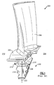
- Figure 1 illustrates a prior art turbine blade 200.
- a platform 202 is provided at a radially inner portion of the turbine blade 200, and an airfoil 204 extends radially outwardly from the platform 202.
- a base 206 located under the platform 202 includes a shelf 208.
- a central longitudinal axis Y passes through a center of a width V of a bottom surface 222 of the base 206 of the turbine blade 200.
- a distance X 1 is defined between the central longitudinal axis Y of the base 206 and an outer surface 210 of the shelf 208 on a suction side 212 of the turbine blade 200
- a distance X 2 is defined between the central longitudinal axis Y of the base 206 and an outer surface 218 of the shelf 208 on an opposing pressure side 220 of the turbine blade 200.
- the distance X 1 and the distance X 2 are substantially equal and together define a width of the turbine blade 200.
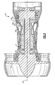
- an attachment portion 214 of the base 206 of the turbine blade 200 is received in a blade retention slot 54 of a turbine disk 46.
- the shelves 208 of the turbine blades 200 are located outside the turbine disk 46 and are separated by a space 216.
- the prior art turbine blade 200 does not include any features that would distinguish the prior art turbine blade 200 from a turbine blade having a different design.
- a turbine blade in one example, includes a platform, an airfoil located on one side of the platform, and a base located on an opposite side of the platform.
- the base includes an attachment portion that is receivable in a blade retention slot of a turbine disk and a shelf located outside the turbine disk.
- the shelf includes a mistake proof feature that projects from an outer surface of the shelf.
- a turbine assembly in another example, includes a turbine disk including a plurality of blade retention slots and a plurality of turbine blades.
- One turbine blade is received in each of the blade retention slots.
- Each of the plurality of turbine blades includes a platform, an airfoil located on one side of the platform, and a base located on an opposite side of the platform.
- the base includes an attachment portion that is receivable in one of the blade retention slots of the turbine disk and a shelf located outside the turbine disk.
- the shelf includes a mistake proof feature that projects from an outer surface of the shelf. A space is defined between the mistake proof feature of each of the turbine blades and an outer surface of the shelf of an adjacent turbine blade.
- a gas turbine engine 10 such as a turbofan gas turbine engine, is circumferentially disposed about an engine centerline (or axial centerline axis 12).
- the gas turbine engine 10 includes a fan 14, compressors 16 and 17, a combustion section 18 and turbines 20 and 21.
- This application extends to engines without a fan, and with more or fewer sections.
- air is compressed in the compressors 16 and 17, mixed with fuel and burned in the combustion section 18, and expanded in turbines 20 and 21.
- the turbines 20 and 21 include rotors 22 which rotate in response to the expansion, driving the compressors 16 and 17 and the fan 14.
- the turbines 20 and 21 include alternating rows of rotating airfoils or turbine blades 24 and static airfoils or vanes 26.
- FIG. 3 is schematic, and the turbine blades 24 and the vanes 26 are removable from the rotors 22 in this example. It should be understood that this view is included simply to provide a basic understanding of the sections in a gas turbine engine 10 and not to limit the invention. This invention extends to all types of gas turbine engines for all types of applications.
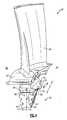
- Figure 4 illustrates the turbine blade 24 having a pressure side 28 and a suction side 30.
- a platform 32 is provided at a radially inner portion of the turbine blade 24, and an airfoil 34 extends radially outwardly from the platform 32 (as seen from the axial centerline axis 12).
- a base 36 is located under the platform 32.
- the base 36 includes a shelf 38 and an attachment portion 40 having an irregular surface including fingers 42 and grooves 44.
- the shelf 38 is located above the attachment portion 40 and below the platform 32.
- a central longitudinal axis B passes through a center of a width E of a bottom surface 72 of the base 36 of the turbine blade 24.
- a distance C 1 is defined between the central longitudinal axis B and an outer surface 64 of the shelf 38 on the suction side 30 of the turbine blade 24, and a distance C 2 is defined between the central longitudinal axis B and an outer surface 66 of the shelf 38 on the pressure side 28 of the turbine blade 24.
- the distance C 1 is less than the distance C 2 and less than the distance X 1 of the prior art turbine blade 200.
- the distance C 1 and the distance C 2 together define a width of the turbine blade 24.
- the shelf 38 on the suction side 30 includes a cutback or trimmed back portion to prevent interference with an adjacent turbine blade, as described below.
- the shape and distance C 2 of the shelf 38 on the suction side 30 of the turbine blade 24 can be formed or defined by casting, machining or casting with further machining.
- the shelf 38 also has a depth D defined between a front and a back of the base 36, and the fingers 42 and the grooves 44 extend along the depth D.
- the depth D is substantially perpendicular to the central longitudinal axis B.
- the turbine disk 46 includes a first face 48, an opposing second face 50, and an outer perimeter surface 52 that extends axially between the first face 48 and the opposing second face 50.
- a plurality of blade retention slots 54 extend through the turbine disk 46 from the first face 48 and the opposing second face 50.
- the blade retention slots 54 have a profile that is complementary to the profile of the base 36 of the turbine blade 24.
- the attachment portion 40 of the base 36 of the turbine blade 24 is aligned with one of the blade retention slots 54.
- the fingers 42 of the turbine blade 24 align with grooves 60 of the blade retention slot 54, and the grooves 44 of the turbine blade 24 align with fingers 58 of the blade retention slot 54.
- the turbine blade 24 is then slid relative to the turbine disk 46 to receive the turbine blade 24 in the blade retention slot 54.
- the shelf 38 is located outside the outer perimeter surface 52 of the turbine disk 46.
- Each blade retention slot 54 receives the base 36 of one of the turbine blades 24.
- the turbine blade 24 includes a tab 62 located on the outer surface 66 of the shelf 38 on the pressure side 28 of the turbine blade 24 in this example.
- the tab 62 is located substantially in a center of the depth D of the shelf 38. Locating the tab 62 in the center of the depth D of the shelf 38 reduces impact on blade stress, balance and rotor life.
- the tab 62 has a depth W that is less than the depth D of the shelf 38.
- the tab 62 can have a depth W that is equal to the depth D of the shelf 38.
- the tab 62 extends substantially perpendicular to the outer surface 66 of the shelf 38.
- the tab 62 also has a width Q defined between the outer surface 66 of the shelf 38 and an outer surface 70 of the tab 62, the outer surfaces 66 and 70 being substantially parallel.
- the tab 62 is disclosed as being located on the pressure side 28 of the turbine blade 24, it is to be understood that the tab 62 could also be located on the suction side 30 of the turbine blade 24.
- the tab 62 can be formed during casting of the turbine blade 24 to provide a visual and measurable feature on the turbine blade 24 during manufacture and assembly of the turbine blade 24. Once cast, the tab 62 can be machined to further define the shape of the tab 62. The tab 62 prevents the turbine blade 24 from being mistakenly assembled with, or confused for, the prior art turbine blade 200 during machining and assembly. Mixing the turbine blade 24 and the prior art turbine blade 200 can cause vibrations in the turbine engine 10. The tab 62 provides a low stress and balance-neutral approach to preventing misassembled turbine blades 24.
- the tab 62 of the turbine blade 24a of the turbine blade 24a faces the outer surface 64 of the shelf 38 of the turbine blade 24b.
- the shelf 38 located on the suction side 30 of the turbine blade 24b has a reduced distance C 1 (due to the cut back or trimmed back portion), as compared to the distance X 1 of the prior art turbine blades 200a and 200b, the tab 62 does not hinder installation of the turbine blades 24a and 24b as a space 68 is defined between the outer surface 70 of the tab 62 and the outer surface 64 of the shelf 38, maintaining proper clearances between the turbine blades 24.
- the tab 62 of the turbine blades 24a and 24b prevents inadvertent installation of both the prior art turbine blades 200a and 200b and the turbine blades 24a and 24b in the same turbine disk 46.
- a space 216 is defined between the outer surface 218 of the shelf 208 of one prior art turbine blade 200a and the outer surface 210 of the shelf 208 of the adjacent prior art turbine blade 200b, providing a space 216 with a proper clearance between the adjacent turbine blades 200a and 200b.
- the turbine blades 24a and 24b are installed in the blade retention slots 54a and 54b, respectively, of the turbine disk 46. If the prior art turbine blade 200a is attempted to be installed in the blade retention slot 54c, the tab 62 prevents insertion of the turbine blade 200a into the adjacent blade retention slot 54c.
- the shelf 208 of the turbine blade 200a (which has a distance X 1 between the outer surface 210 of the shelf 208 and the central longitudinal axis Y that is greater than the distance C 1 between the outer surface 64 of the shelf 38 of the turbine blade 24 and the longitudinal central axis B) contacts the tab 62, preventing insertion of the prior art turbine blade 200 in the blade retention slot 54c of the turbine disk 46.
- only turbine blades 24a and 24b can be installed in the turbine disk 46, maintaining proper clearances between the turbine blades 24a and 24b.
- the prior art turbine blades 200a and 200b are installed into the blade retention slots 54c and 54d, respectively, of the turbine disk 46. If a turbine blade 24b is attempted to be installed in the blade retention slot 54b, the shelf 208 (which has a distance X 1 between the outer surface 210 of the shelf 208 and the central longitudinal axis Y that is greater than the distance C 1 between the outer surface 64 of the shelf 38 of the turbine blade 24 and the longitudinal central axis B of the turbine blade 24b) prevents insertion of the turbine blade 24b into the adjacent blade retention slot 54b. That is, the tab 62 of the turbine blade 24b contacts the shelf 208 of the prior art turbine blade 200a, preventing insertion of the turbine blade 24b into the blade retention slot 54b. In this example, only turbine blades 200a and 200b can be installed in the turbine disk 46, maintaining proper clearances between the turbine blades 200a and 200b.
- Figure 8 shows the turbine blade 24b installed next to the turbine blade 200a, this is not possible due to the width Q of the tab 62 of the turbine blade 24b and the distance X 1 between the outer surface 210 of the shelf 208 and the central longitudinal axis Y of the prior art turbine blade 200a.
- a portion of the tab 62 of the turbine blade 24b is shown in phantom lines to illustrate the interference of the tab 62 relative to the outer surface 210 of the shelf 208 of the prior art turbine blade 200a.
- the turbine blade 200a and the turbine blade 24b cannot be installed next to each other.
Landscapes
- Engineering & Computer Science (AREA)
- Mechanical Engineering (AREA)
- General Engineering & Computer Science (AREA)
- Turbine Rotor Nozzle Sealing (AREA)
Abstract
Description
- This application relates generally to a turbine blade including a mistake proof tab that prevents intermixing of different blade designs in a turbine disk of a turbine engine.
- Gas turbine engines generally include a turbine disk and a plurality of removable turbine blades. The turbine blades should all have a similar blade design. Intermixing of blade designs can affect operation and/or reliability of the gas turbine engine.
-
Figure 1 illustrates a priorart turbine blade 200. Aplatform 202 is provided at a radially inner portion of theturbine blade 200, and anairfoil 204 extends radially outwardly from theplatform 202. Abase 206 located under theplatform 202 includes ashelf 208. A central longitudinal axis Y passes through a center of a width V of abottom surface 222 of thebase 206 of theturbine blade 200. A distance X1 is defined between the central longitudinal axis Y of thebase 206 and anouter surface 210 of theshelf 208 on asuction side 212 of theturbine blade 200, and a distance X2 is defined between the central longitudinal axis Y of thebase 206 and anouter surface 218 of theshelf 208 on anopposing pressure side 220 of theturbine blade 200. The distance X1 and the distance X2 are substantially equal and together define a width of theturbine blade 200. - As shown in
Figure 2 , anattachment portion 214 of thebase 206 of theturbine blade 200 is received in ablade retention slot 54 of aturbine disk 46. Theshelves 208 of theturbine blades 200 are located outside theturbine disk 46 and are separated by aspace 216. The priorart turbine blade 200 does not include any features that would distinguish the priorart turbine blade 200 from a turbine blade having a different design. - There is a need in the art for a turbine blade that includes a mistake proof feature that prevents intermixing of turbine blade designs in a turbine disk of a turbine engine.
- In one example, a turbine blade includes a platform, an airfoil located on one side of the platform, and a base located on an opposite side of the platform. The base includes an attachment portion that is receivable in a blade retention slot of a turbine disk and a shelf located outside the turbine disk. The shelf includes a mistake proof feature that projects from an outer surface of the shelf.
- In another example, a turbine assembly includes a turbine disk including a plurality of blade retention slots and a plurality of turbine blades. One turbine blade is received in each of the blade retention slots. Each of the plurality of turbine blades includes a platform, an airfoil located on one side of the platform, and a base located on an opposite side of the platform. The base includes an attachment portion that is receivable in one of the blade retention slots of the turbine disk and a shelf located outside the turbine disk. The shelf includes a mistake proof feature that projects from an outer surface of the shelf. A space is defined between the mistake proof feature of each of the turbine blades and an outer surface of the shelf of an adjacent turbine blade.
- These and other features of the present invention can be best understood from the following specification and drawings, the following of which is a brief description.
-
-
Figure 1 illustrates a perspective view of a prior art turbine blade; -
Figure 2 illustrates a side view of the prior art turbine blade attached to a turbine disk; -
Figure 3 illustrates a simplified cross-sectional view of a standard gas turbine engine; -
Figure 4 illustrates a perspective view of a turbine blade; -
Figure 5 illustrates a front view of the turbine disk; -
Figure 6 illustrates a side view of the turbine disk; -
Figure 7 illustrates the turbine blade ofFigure 4 attached to the turbine disk; and -
Figure 8 illustrates the prior art turbine blade ofFigure 1 and the turbine blade ofFigure 4 attached to a turbine disk. - As shown in
Figure 3 , agas turbine engine 10, such as a turbofan gas turbine engine, is circumferentially disposed about an engine centerline (or axial centerline axis 12). Thegas turbine engine 10 includes afan 14,compressors combustion section 18 andturbines compressors combustion section 18, and expanded inturbines turbines rotors 22 which rotate in response to the expansion, driving thecompressors fan 14. Theturbines turbine blades 24 and static airfoils orvanes 26. -
Figure 3 is schematic, and theturbine blades 24 and thevanes 26 are removable from therotors 22 in this example. It should be understood that this view is included simply to provide a basic understanding of the sections in agas turbine engine 10 and not to limit the invention. This invention extends to all types of gas turbine engines for all types of applications. -
Figure 4 illustrates theturbine blade 24 having apressure side 28 and asuction side 30. Aplatform 32 is provided at a radially inner portion of theturbine blade 24, and anairfoil 34 extends radially outwardly from the platform 32 (as seen from the axial centerline axis 12). Abase 36 is located under theplatform 32. Thebase 36 includes ashelf 38 and anattachment portion 40 having an irregularsurface including fingers 42 andgrooves 44. Theshelf 38 is located above theattachment portion 40 and below theplatform 32. - A central longitudinal axis B passes through a center of a width E of a bottom surface 72 of the
base 36 of theturbine blade 24. A distance C1 is defined between the central longitudinal axis B and anouter surface 64 of theshelf 38 on thesuction side 30 of theturbine blade 24, and a distance C2 is defined between the central longitudinal axis B and anouter surface 66 of theshelf 38 on thepressure side 28 of theturbine blade 24. The distance C1 is less than the distance C2 and less than the distance X1 of the priorart turbine blade 200. The distance C1 and the distance C2 together define a width of theturbine blade 24. In one example, theshelf 38 on thesuction side 30 includes a cutback or trimmed back portion to prevent interference with an adjacent turbine blade, as described below. The shape and distance C2 of theshelf 38 on thesuction side 30 of theturbine blade 24 can be formed or defined by casting, machining or casting with further machining. - The
shelf 38 also has a depth D defined between a front and a back of thebase 36, and thefingers 42 and thegrooves 44 extend along the depth D. The depth D is substantially perpendicular to the central longitudinal axis B. - As shown in
Figures 5 and 6 , theturbine disk 46 includes afirst face 48, an opposingsecond face 50, and anouter perimeter surface 52 that extends axially between thefirst face 48 and the opposingsecond face 50. A plurality ofblade retention slots 54 extend through theturbine disk 46 from thefirst face 48 and the opposingsecond face 50. - The
blade retention slots 54 have a profile that is complementary to the profile of thebase 36 of theturbine blade 24. When theturbine blade 24 is to be installed in theturbine disk 46, theattachment portion 40 of thebase 36 of theturbine blade 24 is aligned with one of theblade retention slots 54. Thefingers 42 of theturbine blade 24 align withgrooves 60 of theblade retention slot 54, and thegrooves 44 of theturbine blade 24 align withfingers 58 of theblade retention slot 54. Theturbine blade 24 is then slid relative to theturbine disk 46 to receive theturbine blade 24 in theblade retention slot 54. Theshelf 38 is located outside theouter perimeter surface 52 of theturbine disk 46. Eachblade retention slot 54 receives thebase 36 of one of theturbine blades 24. - Returning to
Figure 4 , theturbine blade 24 includes atab 62 located on theouter surface 66 of theshelf 38 on thepressure side 28 of theturbine blade 24 in this example. Thetab 62 is located substantially in a center of the depth D of theshelf 38. Locating thetab 62 in the center of the depth D of theshelf 38 reduces impact on blade stress, balance and rotor life. In one example, thetab 62 has a depth W that is less than the depth D of theshelf 38. However, thetab 62 can have a depth W that is equal to the depth D of theshelf 38. - The
tab 62 extends substantially perpendicular to theouter surface 66 of theshelf 38. Thetab 62 also has a width Q defined between theouter surface 66 of theshelf 38 and anouter surface 70 of thetab 62, theouter surfaces tab 62 is disclosed as being located on thepressure side 28 of theturbine blade 24, it is to be understood that thetab 62 could also be located on thesuction side 30 of theturbine blade 24. - The
tab 62 can be formed during casting of theturbine blade 24 to provide a visual and measurable feature on theturbine blade 24 during manufacture and assembly of theturbine blade 24. Once cast, thetab 62 can be machined to further define the shape of thetab 62. Thetab 62 prevents theturbine blade 24 from being mistakenly assembled with, or confused for, the priorart turbine blade 200 during machining and assembly. Mixing theturbine blade 24 and the priorart turbine blade 200 can cause vibrations in theturbine engine 10. Thetab 62 provides a low stress and balance-neutral approach to preventingmisassembled turbine blades 24. - As shown in
Figure 7 , when twoturbine blades blade retention slots 54 of theturbine disk 46, aspace 68 is defined between theouter surface 70 of thetab 62 of theturbine blade 24a and theouter surface 64 of theshelf 38 of theturbine blade 24b, providing a proper clearance orspace 68 between theadjacent turbine blades suction side 30 of theshelf 38 is reduced, thetab 62 of theturbine blade 24a does not engage or contact theouter surface 64 of theshelf 38 of theturbine blade 24b, allowing insertion of both theturbine blades turbine disk 46. - When two
turbine blades blade retention slots 54a and 54b, respectively, of theturbine disk 46, thetab 62 of theturbine blade 24a of theturbine blade 24a faces theouter surface 64 of theshelf 38 of theturbine blade 24b. As theshelf 38 located on thesuction side 30 of theturbine blade 24b has a reduced distance C1 (due to the cut back or trimmed back portion), as compared to the distance X1 of the priorart turbine blades tab 62 does not hinder installation of theturbine blades space 68 is defined between theouter surface 70 of thetab 62 and theouter surface 64 of theshelf 38, maintaining proper clearances between theturbine blades 24. Thetab 62 of theturbine blades art turbine blades turbine blades same turbine disk 46. - As shown in
Figure 8 , when two priorart turbine blade blade retention slots turbine disk 46, aspace 216 is defined between theouter surface 218 of theshelf 208 of one priorart turbine blade 200a and theouter surface 210 of theshelf 208 of the adjacent priorart turbine blade 200b, providing aspace 216 with a proper clearance between theadjacent turbine blades - In one example, the
turbine blades blade retention slots 54a and 54b, respectively, of theturbine disk 46. If the priorart turbine blade 200a is attempted to be installed in theblade retention slot 54c, thetab 62 prevents insertion of theturbine blade 200a into the adjacentblade retention slot 54c. Theshelf 208 of theturbine blade 200a (which has a distance X1 between theouter surface 210 of theshelf 208 and the central longitudinal axis Y that is greater than the distance C1 between theouter surface 64 of theshelf 38 of theturbine blade 24 and the longitudinal central axis B) contacts thetab 62, preventing insertion of the priorart turbine blade 200 in theblade retention slot 54c of theturbine disk 46. In this example, onlyturbine blades turbine disk 46, maintaining proper clearances between theturbine blades - In another example, the prior
art turbine blades blade retention slots turbine disk 46. If aturbine blade 24b is attempted to be installed in theblade retention slot 54b, the shelf 208 (which has a distance X1 between theouter surface 210 of theshelf 208 and the central longitudinal axis Y that is greater than the distance C1 between theouter surface 64 of theshelf 38 of theturbine blade 24 and the longitudinal central axis B of theturbine blade 24b) prevents insertion of theturbine blade 24b into the adjacentblade retention slot 54b. That is, thetab 62 of theturbine blade 24b contacts theshelf 208 of the priorart turbine blade 200a, preventing insertion of theturbine blade 24b into theblade retention slot 54b. In this example, onlyturbine blades turbine disk 46, maintaining proper clearances between theturbine blades - Although
Figure 8 shows theturbine blade 24b installed next to theturbine blade 200a, this is not possible due to the width Q of thetab 62 of theturbine blade 24b and the distance X1 between theouter surface 210 of theshelf 208 and the central longitudinal axis Y of the priorart turbine blade 200a. As shown inFigure 8 , a portion of thetab 62 of theturbine blade 24b is shown in phantom lines to illustrate the interference of thetab 62 relative to theouter surface 210 of theshelf 208 of the priorart turbine blade 200a. As theouter surface 210 of theshelf 208 and thetab 62 occupy the same space, theturbine blade 200a and theturbine blade 24b cannot be installed next to each other. - The foregoing description is only exemplary of the principles of the invention. Many modifications and variations are possible in light of the above teachings. It is, therefore, to be understood that within the scope of the appended claims, the invention may be practiced otherwise than using the example embodiments which have been specifically described. For that reason the following claims should be studied to determine the true scope and content of this invention.
Claims (10)
- A turbine blade (24) comprising:a platform (32);an airfoil (34) located on one side of the platform (32); anda base (36) located on an opposing side of the platform (32), the base (36) including an attachment portion (40) that is receivable in a blade retention slot (54) of a turbine disk (46) and a shelf (38) to be located outside the turbine disk (46),wherein the turbine blade (24) includes a pressure side (28) and an opposing suction side (30), and a mistake proof feature (62) projects from a first outer surface (66) of the shelf (38) on one of the pressure side (28) and the opposing suction side (30).
- The turbine blade as recited in claim 1 wherein the mistake proof feature (62) is located on the pressure side (28) of the shelf (38) of the turbine blade (24).
- The turbine blade as recited in claim 1 or 2 wherein the shelf (38) has a depth (D) extending from a front surface to a rear surface of the base (36) and the mistake proof feature (62) has a depth (W), wherein the depth (W) of the mistake proof feature (62) is less than the depth (D) of the shelf (38).
- The turbine blade as recited in claim 3 wherein the mistake proof feature (62) is centered relative to the depth (D) of the shelf (38).
- The turbine blade as recited in any preceding claim wherein the mistake proof feature is a tab (62).
- The turbine blade as recited in any preceding claim wherein the mistake proof feature (62) extends substantially perpendicular to the first outer surface (66) of the shelf (38).
- The turbine blade as recited in any preceding claim wherein the attachment portion (40) of the base (36) includes a plurality of grooves (44) and a plurality of fingers (42).
- The turbine blade as recited in any preceding claim wherein the first outer surface (66) is located on the pressure side (28) of the turbine blade (24) and an opposing second outer surface (64) is located on the opposing suction side (30) of the turbine blade (24), wherein a central longitudinal axis (B) passes through a center of a width (E) of a bottom surface (72) of the base (36), wherein a distance (C1) between the opposing second outer surface (64) and the central longitudinal axis (B) is less than a distance (C2) between the first outer surface (66) and the central longitudinal axis (B).
- A turbine blade (24) comprising:a platform (32);an airfoil (34) located on one side of the platform (32); anda base (36) located on an opposing side of the platform (32), the base (36) including an attachment portion (40) that is receivable in a blade retention slot (54) of a turbine disk (46) and a shelf (38) to be located outside the turbine disk (46),wherein the turbine blade (24) includes a pressure side (28) and an opposing suction side (30), and a mistake proof feature (62) is provided on one of the pressure side (28) and the opposing suction side (30) of said shelf (38).
- A turbine assembly comprising:a turbine disk (46) including a plurality of blade retention slots (54); anda plurality of turbine blades (24), wherein one of the plurality of turbine blades (24) is received in each of the plurality of blade retention slots (54), and each of the plurality of turbine blades is a turbine blade as recited in any preceding claim,wherein a space (68) is defined between the mistake proof feature (62) of each of the plurality of turbine blades (24) and an opposing second outer surface (64) of the shelf (38) of an adjacent one of the plurality of turbine blades (24).
Applications Claiming Priority (1)
| Application Number | Priority Date | Filing Date | Title |
|---|---|---|---|
| US12/253,537 US8435008B2 (en) | 2008-10-17 | 2008-10-17 | Turbine blade including mistake proof feature |
Publications (3)
| Publication Number | Publication Date |
|---|---|
| EP2177716A2 true EP2177716A2 (en) | 2010-04-21 |
| EP2177716A3 EP2177716A3 (en) | 2013-11-06 |
| EP2177716B1 EP2177716B1 (en) | 2016-04-13 |
Family
ID=40800458
Family Applications (1)
| Application Number | Title | Priority Date | Filing Date |
|---|---|---|---|
| EP09251315.9A Not-in-force EP2177716B1 (en) | 2008-10-17 | 2009-05-14 | Turbine blade with mistake proof feature and corresponding assembly |
Country Status (2)
| Country | Link |
|---|---|
| US (1) | US8435008B2 (en) |
| EP (1) | EP2177716B1 (en) |
Cited By (1)
| Publication number | Priority date | Publication date | Assignee | Title |
|---|---|---|---|---|
| US10047609B2 (en) | 2012-09-25 | 2018-08-14 | United Technologies Corporation | Airfoil array with airfoils that differ in geometry according to geometry classes |
Families Citing this family (10)
| Publication number | Priority date | Publication date | Assignee | Title |
|---|---|---|---|---|
| US20120034086A1 (en) * | 2010-08-04 | 2012-02-09 | General Electric Company | Swing axial entry dovetail for steam turbine buckets |
| US20130318996A1 (en) * | 2012-06-01 | 2013-12-05 | General Electric Company | Cooling assembly for a bucket of a turbine system and method of cooling |
| US9587495B2 (en) | 2012-06-29 | 2017-03-07 | United Technologies Corporation | Mistake proof damper pocket seals |
| US20140030084A1 (en) * | 2012-07-24 | 2014-01-30 | General Electric Company | Article of manufacture for turbomachine |
| US9670790B2 (en) | 2012-09-28 | 2017-06-06 | United Technologies Corporation | Turbine vane with mistake reduction feature |
| EP2904252B2 (en) * | 2012-10-01 | 2020-11-25 | United Technologies Corporation | Static guide vane with internal hollow channels |
| WO2014164252A1 (en) * | 2013-03-13 | 2014-10-09 | United Technologies Corporation | Damper mass distribution to prevent damper rotation |
| JP7064076B2 (en) | 2018-03-27 | 2022-05-10 | 三菱重工業株式会社 | How to tune turbine blades, turbines, and natural frequencies of turbine blades |
| US11401814B2 (en) | 2020-01-17 | 2022-08-02 | Raytheon Technologies Corporation | Rotor assembly with internal vanes |
| US11286781B2 (en) * | 2020-01-17 | 2022-03-29 | Raytheon Technologies Corporation | Multi-disk bladed rotor assembly for rotational equipment |
Family Cites Families (16)
| Publication number | Priority date | Publication date | Assignee | Title |
|---|---|---|---|---|
| DE1074594B (en) * | 1961-02-23 | 1960-02-04 | D Napier &. Son Limited, London | Attachment of hollow hydrofoil profiled axial turbines or axial compressor blades |
| US3572968A (en) | 1969-04-11 | 1971-03-30 | Gen Electric | Turbine bucket cover |
| JPS54141907A (en) | 1978-04-03 | 1979-11-05 | Toshiba Corp | Connector for moving blades of turbine |
| JPS5925087B2 (en) | 1980-06-04 | 1984-06-14 | 株式会社日立製作所 | Turbine rotor blade coupling device |
| US4784573A (en) | 1987-08-17 | 1988-11-15 | United Technologies Corporation | Turbine blade attachment |
| US5135354A (en) | 1990-09-14 | 1992-08-04 | United Technologies Corporation | Gas turbine blade and disk |
| US5281097A (en) * | 1992-11-20 | 1994-01-25 | General Electric Company | Thermal control damper for turbine rotors |
| US5228835A (en) * | 1992-11-24 | 1993-07-20 | United Technologies Corporation | Gas turbine blade seal |
| US5431543A (en) | 1994-05-02 | 1995-07-11 | Westinghouse Elec Corp. | Turbine blade locking assembly |
| US5827047A (en) * | 1996-06-27 | 1998-10-27 | United Technologies Corporation | Turbine blade damper and seal |
| US6171058B1 (en) * | 1999-04-01 | 2001-01-09 | General Electric Company | Self retaining blade damper |
| US6371727B1 (en) | 2000-06-05 | 2002-04-16 | The Boeing Company | Turbine blade tip shroud enclosed friction damper |
| US6951447B2 (en) | 2003-12-17 | 2005-10-04 | United Technologies Corporation | Turbine blade with trailing edge platform undercut |
| GB2411697B (en) | 2004-03-06 | 2006-06-21 | Rolls Royce Plc | A turbine having a cooling arrangement |
| US7371048B2 (en) | 2005-05-27 | 2008-05-13 | United Technologies Corporation | Turbine blade trailing edge construction |
| US7467924B2 (en) * | 2005-08-16 | 2008-12-23 | United Technologies Corporation | Turbine blade including revised platform |
-
2008
- 2008-10-17 US US12/253,537 patent/US8435008B2/en not_active Expired - Fee Related
-
2009
- 2009-05-14 EP EP09251315.9A patent/EP2177716B1/en not_active Not-in-force
Cited By (1)
| Publication number | Priority date | Publication date | Assignee | Title |
|---|---|---|---|---|
| US10047609B2 (en) | 2012-09-25 | 2018-08-14 | United Technologies Corporation | Airfoil array with airfoils that differ in geometry according to geometry classes |
Also Published As
| Publication number | Publication date |
|---|---|
| US8435008B2 (en) | 2013-05-07 |
| US20100098547A1 (en) | 2010-04-22 |
| EP2177716A3 (en) | 2013-11-06 |
| EP2177716B1 (en) | 2016-04-13 |
Similar Documents
| Publication | Publication Date | Title |
|---|---|---|
| EP2177716B1 (en) | Turbine blade with mistake proof feature and corresponding assembly | |
| EP1451446B1 (en) | Turbine blade pocket shroud | |
| EP2372088B1 (en) | Turbofan flow path trenches | |
| US8038411B2 (en) | Compressor turbine blade airfoil profile | |
| US7559749B2 (en) | LP turbine vane airfoil profile | |
| EP1744013B1 (en) | Method for loading and tangential locking of rotor blades and corresponding rotor blade | |
| US7618234B2 (en) | Hook ring segment for a compressor vane | |
| EP3219910B1 (en) | Disc for a rotor of a gas turbine engine, and a rotor and a gas turbine comprising the same | |
| GB2097480A (en) | Rotor blade fixing in circumferential slot | |
| EP2570612A1 (en) | Turbomachine secondary seal assembly | |
| US10907491B2 (en) | Sealing system for a rotary machine and method of assembling same | |
| WO2013130570A1 (en) | Turbine engine rotor blade groove | |
| US7708529B2 (en) | Rotor of a turbo engine, e.g., a gas turbine rotor | |
| US20180274381A1 (en) | Gas turbine engine component incorporating a seal slot | |
| EP3489464B1 (en) | Seal structure for gas turbine rotor blade | |
| US9739159B2 (en) | Method and system for relieving turbine rotor blade dovetail stress | |
| EP3219912B1 (en) | Cover plate, rotor assembly, and gas turbine | |
| EP2527595A2 (en) | Balancing of rotatable components for a gas turbine engine | |
| EP3219909B1 (en) | Disc for a gas turbine engine, rotor assembly, and gas turbine | |
| EP2863016A1 (en) | Turbine with bucket fixing means | |
| EP3438410B1 (en) | Sealing system for a rotary machine | |
| US7056094B2 (en) | Rotor and a retaining plate for the same | |
| EP3550111A1 (en) | Turbine blade shroud for gas turbine engine with power turbine and method of manufacturing same | |
| EP3219908B1 (en) | Disc for a rotor assembly of a gas turbine, rotor assembly, and gas turbine |
Legal Events
| Date | Code | Title | Description |
|---|---|---|---|
| PUAI | Public reference made under article 153(3) epc to a published international application that has entered the european phase |
Free format text: ORIGINAL CODE: 0009012 |
|
| AK | Designated contracting states |
Kind code of ref document: A2 Designated state(s): AT BE BG CH CY CZ DE DK EE ES FI FR GB GR HR HU IE IS IT LI LT LU LV MC MK MT NL NO PL PT RO SE SI SK TR |
|
| AX | Request for extension of the european patent |
Extension state: AL BA RS |
|
| PUAL | Search report despatched |
Free format text: ORIGINAL CODE: 0009013 |
|
| AK | Designated contracting states |
Kind code of ref document: A3 Designated state(s): AT BE BG CH CY CZ DE DK EE ES FI FR GB GR HR HU IE IS IT LI LT LU LV MC MK MT NL NO PL PT RO SE SI SK TR |
|
| AX | Request for extension of the european patent |
Extension state: AL BA RS |
|
| RIC1 | Information provided on ipc code assigned before grant |
Ipc: F01D 5/30 20060101AFI20131002BHEP |
|
| 17P | Request for examination filed |
Effective date: 20140502 |
|
| RBV | Designated contracting states (corrected) |
Designated state(s): AT BE BG CH CY CZ DE DK EE ES FI FR GB GR HR HU IE IS IT LI LT LU LV MC MK MT NL NO PL PT RO SE SI SK TR |
|
| GRAP | Despatch of communication of intention to grant a patent |
Free format text: ORIGINAL CODE: EPIDOSNIGR1 |
|
| INTG | Intention to grant announced |
Effective date: 20151103 |
|
| GRAS | Grant fee paid |
Free format text: ORIGINAL CODE: EPIDOSNIGR3 |
|
| GRAA | (expected) grant |
Free format text: ORIGINAL CODE: 0009210 |
|
| AK | Designated contracting states |
Kind code of ref document: B1 Designated state(s): AT BE BG CH CY CZ DE DK EE ES FI FR GB GR HR HU IE IS IT LI LT LU LV MC MK MT NL NO PL PT RO SE SI SK TR |
|
| REG | Reference to a national code |
Ref country code: GB Ref legal event code: FG4D |
|
| REG | Reference to a national code |
Ref country code: AT Ref legal event code: REF Ref document number: 790398 Country of ref document: AT Kind code of ref document: T Effective date: 20160415 Ref country code: CH Ref legal event code: EP |
|
| REG | Reference to a national code |
Ref country code: IE Ref legal event code: FG4D |
|
| REG | Reference to a national code |
Ref country code: DE Ref legal event code: R096 Ref document number: 602009037704 Country of ref document: DE |
|
| REG | Reference to a national code |
Ref country code: LT Ref legal event code: MG4D |
|
| PG25 | Lapsed in a contracting state [announced via postgrant information from national office to epo] |
Ref country code: BE Free format text: LAPSE BECAUSE OF NON-PAYMENT OF DUE FEES Effective date: 20160531 |
|
| REG | Reference to a national code |
Ref country code: AT Ref legal event code: MK05 Ref document number: 790398 Country of ref document: AT Kind code of ref document: T Effective date: 20160413 |
|
| REG | Reference to a national code |
Ref country code: NL Ref legal event code: MP Effective date: 20160413 |
|
| REG | Reference to a national code |
Ref country code: CH Ref legal event code: PCOW Free format text: NEW ADDRESS: 10 FARM SPRINGS RD., FARMINGTON, CT 06032 (US) |
|
| RAP2 | Party data changed (patent owner data changed or rights of a patent transferred) |
Owner name: UNITED TECHNOLOGIES CORPORATION |
|
| REG | Reference to a national code |
Ref country code: FR Ref legal event code: PLFP Year of fee payment: 8 |
|
| PG25 | Lapsed in a contracting state [announced via postgrant information from national office to epo] |
Ref country code: PL Free format text: LAPSE BECAUSE OF FAILURE TO SUBMIT A TRANSLATION OF THE DESCRIPTION OR TO PAY THE FEE WITHIN THE PRESCRIBED TIME-LIMIT Effective date: 20160413 Ref country code: FI Free format text: LAPSE BECAUSE OF FAILURE TO SUBMIT A TRANSLATION OF THE DESCRIPTION OR TO PAY THE FEE WITHIN THE PRESCRIBED TIME-LIMIT Effective date: 20160413 Ref country code: NL Free format text: LAPSE BECAUSE OF FAILURE TO SUBMIT A TRANSLATION OF THE DESCRIPTION OR TO PAY THE FEE WITHIN THE PRESCRIBED TIME-LIMIT Effective date: 20160413 Ref country code: NO Free format text: LAPSE BECAUSE OF FAILURE TO SUBMIT A TRANSLATION OF THE DESCRIPTION OR TO PAY THE FEE WITHIN THE PRESCRIBED TIME-LIMIT Effective date: 20160713 Ref country code: LT Free format text: LAPSE BECAUSE OF FAILURE TO SUBMIT A TRANSLATION OF THE DESCRIPTION OR TO PAY THE FEE WITHIN THE PRESCRIBED TIME-LIMIT Effective date: 20160413 |
|
| PG25 | Lapsed in a contracting state [announced via postgrant information from national office to epo] |
Ref country code: AT Free format text: LAPSE BECAUSE OF FAILURE TO SUBMIT A TRANSLATION OF THE DESCRIPTION OR TO PAY THE FEE WITHIN THE PRESCRIBED TIME-LIMIT Effective date: 20160413 Ref country code: GR Free format text: LAPSE BECAUSE OF FAILURE TO SUBMIT A TRANSLATION OF THE DESCRIPTION OR TO PAY THE FEE WITHIN THE PRESCRIBED TIME-LIMIT Effective date: 20160714 Ref country code: SE Free format text: LAPSE BECAUSE OF FAILURE TO SUBMIT A TRANSLATION OF THE DESCRIPTION OR TO PAY THE FEE WITHIN THE PRESCRIBED TIME-LIMIT Effective date: 20160413 Ref country code: HR Free format text: LAPSE BECAUSE OF FAILURE TO SUBMIT A TRANSLATION OF THE DESCRIPTION OR TO PAY THE FEE WITHIN THE PRESCRIBED TIME-LIMIT Effective date: 20160413 Ref country code: ES Free format text: LAPSE BECAUSE OF FAILURE TO SUBMIT A TRANSLATION OF THE DESCRIPTION OR TO PAY THE FEE WITHIN THE PRESCRIBED TIME-LIMIT Effective date: 20160413 Ref country code: PT Free format text: LAPSE BECAUSE OF FAILURE TO SUBMIT A TRANSLATION OF THE DESCRIPTION OR TO PAY THE FEE WITHIN THE PRESCRIBED TIME-LIMIT Effective date: 20160816 Ref country code: LV Free format text: LAPSE BECAUSE OF FAILURE TO SUBMIT A TRANSLATION OF THE DESCRIPTION OR TO PAY THE FEE WITHIN THE PRESCRIBED TIME-LIMIT Effective date: 20160413 |
|
| PG25 | Lapsed in a contracting state [announced via postgrant information from national office to epo] |
Ref country code: IT Free format text: LAPSE BECAUSE OF FAILURE TO SUBMIT A TRANSLATION OF THE DESCRIPTION OR TO PAY THE FEE WITHIN THE PRESCRIBED TIME-LIMIT Effective date: 20160413 Ref country code: BE Free format text: LAPSE BECAUSE OF FAILURE TO SUBMIT A TRANSLATION OF THE DESCRIPTION OR TO PAY THE FEE WITHIN THE PRESCRIBED TIME-LIMIT Effective date: 20160413 |
|
| REG | Reference to a national code |
Ref country code: CH Ref legal event code: PL |
|
| REG | Reference to a national code |
Ref country code: DE Ref legal event code: R097 Ref document number: 602009037704 Country of ref document: DE |
|
| PG25 | Lapsed in a contracting state [announced via postgrant information from national office to epo] |
Ref country code: LI Free format text: LAPSE BECAUSE OF NON-PAYMENT OF DUE FEES Effective date: 20160531 Ref country code: SK Free format text: LAPSE BECAUSE OF FAILURE TO SUBMIT A TRANSLATION OF THE DESCRIPTION OR TO PAY THE FEE WITHIN THE PRESCRIBED TIME-LIMIT Effective date: 20160413 Ref country code: RO Free format text: LAPSE BECAUSE OF FAILURE TO SUBMIT A TRANSLATION OF THE DESCRIPTION OR TO PAY THE FEE WITHIN THE PRESCRIBED TIME-LIMIT Effective date: 20160413 Ref country code: DK Free format text: LAPSE BECAUSE OF FAILURE TO SUBMIT A TRANSLATION OF THE DESCRIPTION OR TO PAY THE FEE WITHIN THE PRESCRIBED TIME-LIMIT Effective date: 20160413 Ref country code: EE Free format text: LAPSE BECAUSE OF FAILURE TO SUBMIT A TRANSLATION OF THE DESCRIPTION OR TO PAY THE FEE WITHIN THE PRESCRIBED TIME-LIMIT Effective date: 20160413 Ref country code: CH Free format text: LAPSE BECAUSE OF NON-PAYMENT OF DUE FEES Effective date: 20160531 Ref country code: MC Free format text: LAPSE BECAUSE OF FAILURE TO SUBMIT A TRANSLATION OF THE DESCRIPTION OR TO PAY THE FEE WITHIN THE PRESCRIBED TIME-LIMIT Effective date: 20160413 Ref country code: CZ Free format text: LAPSE BECAUSE OF FAILURE TO SUBMIT A TRANSLATION OF THE DESCRIPTION OR TO PAY THE FEE WITHIN THE PRESCRIBED TIME-LIMIT Effective date: 20160413 |
|
| PLBE | No opposition filed within time limit |
Free format text: ORIGINAL CODE: 0009261 |
|
| STAA | Information on the status of an ep patent application or granted ep patent |
Free format text: STATUS: NO OPPOSITION FILED WITHIN TIME LIMIT |
|
| REG | Reference to a national code |
Ref country code: IE Ref legal event code: MM4A |
|
| 26N | No opposition filed |
Effective date: 20170116 |
|
| REG | Reference to a national code |
Ref country code: FR Ref legal event code: PLFP Year of fee payment: 9 |
|
| PG25 | Lapsed in a contracting state [announced via postgrant information from national office to epo] |
Ref country code: SI Free format text: LAPSE BECAUSE OF FAILURE TO SUBMIT A TRANSLATION OF THE DESCRIPTION OR TO PAY THE FEE WITHIN THE PRESCRIBED TIME-LIMIT Effective date: 20160413 Ref country code: IE Free format text: LAPSE BECAUSE OF NON-PAYMENT OF DUE FEES Effective date: 20160514 |
|
| REG | Reference to a national code |
Ref country code: DE Ref legal event code: R082 Ref document number: 602009037704 Country of ref document: DE Representative=s name: SCHMITT-NILSON SCHRAUD WAIBEL WOHLFROM PATENTA, DE |
|
| REG | Reference to a national code |
Ref country code: DE Ref legal event code: R082 Ref document number: 602009037704 Country of ref document: DE Representative=s name: SCHMITT-NILSON SCHRAUD WAIBEL WOHLFROM PATENTA, DE Ref country code: DE Ref legal event code: R081 Ref document number: 602009037704 Country of ref document: DE Owner name: UNITED TECHNOLOGIES CORP. (N.D.GES.D. STAATES , US Free format text: FORMER OWNER: UNITED TECHNOLOGIES CORPORATION, HARTFORD, CONN., US |
|
| REG | Reference to a national code |
Ref country code: FR Ref legal event code: PLFP Year of fee payment: 10 |
|
| PG25 | Lapsed in a contracting state [announced via postgrant information from national office to epo] |
Ref country code: CY Free format text: LAPSE BECAUSE OF FAILURE TO SUBMIT A TRANSLATION OF THE DESCRIPTION OR TO PAY THE FEE WITHIN THE PRESCRIBED TIME-LIMIT Effective date: 20160413 Ref country code: HU Free format text: LAPSE BECAUSE OF FAILURE TO SUBMIT A TRANSLATION OF THE DESCRIPTION OR TO PAY THE FEE WITHIN THE PRESCRIBED TIME-LIMIT; INVALID AB INITIO Effective date: 20090514 |
|
| PG25 | Lapsed in a contracting state [announced via postgrant information from national office to epo] |
Ref country code: LU Free format text: LAPSE BECAUSE OF NON-PAYMENT OF DUE FEES Effective date: 20160514 Ref country code: MK Free format text: LAPSE BECAUSE OF FAILURE TO SUBMIT A TRANSLATION OF THE DESCRIPTION OR TO PAY THE FEE WITHIN THE PRESCRIBED TIME-LIMIT Effective date: 20160413 Ref country code: MT Free format text: LAPSE BECAUSE OF NON-PAYMENT OF DUE FEES Effective date: 20160531 Ref country code: TR Free format text: LAPSE BECAUSE OF FAILURE TO SUBMIT A TRANSLATION OF THE DESCRIPTION OR TO PAY THE FEE WITHIN THE PRESCRIBED TIME-LIMIT Effective date: 20160413 Ref country code: IS Free format text: LAPSE BECAUSE OF FAILURE TO SUBMIT A TRANSLATION OF THE DESCRIPTION OR TO PAY THE FEE WITHIN THE PRESCRIBED TIME-LIMIT Effective date: 20160413 |
|
| PG25 | Lapsed in a contracting state [announced via postgrant information from national office to epo] |
Ref country code: BG Free format text: LAPSE BECAUSE OF FAILURE TO SUBMIT A TRANSLATION OF THE DESCRIPTION OR TO PAY THE FEE WITHIN THE PRESCRIBED TIME-LIMIT Effective date: 20160413 |
|
| REG | Reference to a national code |
Ref country code: DE Ref legal event code: R081 Ref document number: 602009037704 Country of ref document: DE Owner name: RAYTHEON TECHNOLOGIES CORPORATION (N.D.GES.D.S, US Free format text: FORMER OWNER: UNITED TECHNOLOGIES CORP. (N.D.GES.D. STAATES DELAWARE), FARMINGTON, CONN., US |
|
| P01 | Opt-out of the competence of the unified patent court (upc) registered |
Effective date: 20230519 |
|
| PGFP | Annual fee paid to national office [announced via postgrant information from national office to epo] |
Ref country code: FR Payment date: 20230420 Year of fee payment: 15 Ref country code: DE Payment date: 20230419 Year of fee payment: 15 |
|
| PGFP | Annual fee paid to national office [announced via postgrant information from national office to epo] |
Ref country code: GB Payment date: 20230420 Year of fee payment: 15 |
|
| REG | Reference to a national code |
Ref country code: DE Ref legal event code: R119 Ref document number: 602009037704 Country of ref document: DE |
|
| GBPC | Gb: european patent ceased through non-payment of renewal fee |
Effective date: 20240514 |
|
| PG25 | Lapsed in a contracting state [announced via postgrant information from national office to epo] |
Ref country code: DE Free format text: LAPSE BECAUSE OF NON-PAYMENT OF DUE FEES Effective date: 20241203 |
|
| PG25 | Lapsed in a contracting state [announced via postgrant information from national office to epo] |
Ref country code: FR Free format text: LAPSE BECAUSE OF NON-PAYMENT OF DUE FEES Effective date: 20240531 |
|
| PG25 | Lapsed in a contracting state [announced via postgrant information from national office to epo] |
Ref country code: GB Free format text: LAPSE BECAUSE OF NON-PAYMENT OF DUE FEES Effective date: 20240514 |