EP2177248A1 - Racquet stringing machine - Google Patents
Racquet stringing machine Download PDFInfo
- Publication number
- EP2177248A1 EP2177248A1 EP09016101A EP09016101A EP2177248A1 EP 2177248 A1 EP2177248 A1 EP 2177248A1 EP 09016101 A EP09016101 A EP 09016101A EP 09016101 A EP09016101 A EP 09016101A EP 2177248 A1 EP2177248 A1 EP 2177248A1
- Authority
- EP
- European Patent Office
- Prior art keywords
- stringing
- resistance assembly
- turntable
- stand
- axis
- Prior art date
- Legal status (The legal status is an assumption and is not a legal conclusion. Google has not performed a legal analysis and makes no representation as to the accuracy of the status listed.)
- Granted
Links
Images




Classifications
-
- A—HUMAN NECESSITIES
- A63—SPORTS; GAMES; AMUSEMENTS
- A63B—APPARATUS FOR PHYSICAL TRAINING, GYMNASTICS, SWIMMING, CLIMBING, OR FENCING; BALL GAMES; TRAINING EQUIPMENT
- A63B51/00—Stringing tennis, badminton or like rackets; Strings therefor; Maintenance of racket strings
- A63B51/14—Arrangements for stringing, e.g. for controlling the tension of the strings during stringing
Definitions
- the present invention relates to a machine for stringing racquets.
- This stringing machine has enhanced ergonomic features.
- Stringing machines assist in the process by maintaining the racquet in place and providing desired tension in the strings, but a majority of the work involved is performed by a person. More particularly, a person must align the racquet within the stringing machine, and then string each of the cross or main strings individually, followed by weaving each of the cross and main strings to form the resulting string grid.
- Those in the racquet stringing business often spend many hours a day standing in front of a stringing machine.
- Conventional stringing machines include a stringing platform with a turntable positioned on top of a fixed stand. The turntable spins within a plane parallel to the floor. Because of the fixed orientation of the stand and the planar position of the turntable, the person stringing the racquet must adjust his or her posture to conform to the position of the stringing machine. In particular, one of the racquet stringer's shoulders is often positioned much higher than the other. Also, the fixed orientation of the stringing machine often induces the racquet stringer to hunch over the turntable.
- conventional stringing machines typically include a vertical stand on a base.
- the stand and/or base can interfere with the placement of the stringer's feet and/or legs, leading to additional awkwardness in the stringer's posture.
- the racquet is clamped to the stringing platform and the turntable allows the racquet stringer to manually spin the racquet to adjust the positioning of the racquet with respect to the various steps of the stringing process.
- Turntables on conventional stringing machines are generally free to spin in response to any applied tangential force unless or until a brake is applied, with the brake preventing any further spinning. If the stringing platform were positioned in the stringing machine such that the turntable spins in a plane non-parallel with the floor, namely tilted toward the racquet stringer, the handle of any racquet clamped to the stringing platform would be drawn by gravity to the lowest point within the plane.
- the present invention presents an ergonomically-designed racquet stringing machine for stringing of a racquet by a user.
- the stringing machine includes a base configured for supporting the stringing machine on a generally horizontal surface, a stand having upper and lower end regions, the lower end region of the stand upwardly extending from a first location of the base, an adjustable stringing platform coupled at a second location to the upper end region of the stand, and a string tensioning assembly coupled to the stand.
- the "first location” of the base may be defined as the center of the footprint resulting from the attachment of the stand to the base.
- the “second location” may be defined as the center of the footprint resulting from the attachment of the stringing platform to the stand.
- the "footprint” is a two-dimensional representation of the intersection of two parts that depicts the area of that intersection. The first and second locations define a line that is angled by a predetermined angle from horizontal.
- the stand extends from the base at an angle between about 70 and about 89 degrees from a horizontal plane (1 and 20 degrees from a vertical plane).
- the angle between the stand and the base may be between about 80 and about 85 degrees from a horizontal plane (5 and 10 degrees from a vertical plane), for example 83 degrees from a horizontal plane (7 degrees from a vertical plane).
- This angled orientation of the stand provides ample legroom for the user standing in front of the stringing machine.
- a forward side of the base intended to face the user may define a recessed area for accommodating at least a portion of the user's feet thereby enabling the user to stand closer to the racquet during stringing.
- the angle between the base and the stand may be adjustable.
- a stand adjustment assembly capable of adjusting the angle of the line defined by the first and second locations may be coupled to the base and the stand.
- the stand adjustment assembly may be configured to adjust the angle of the line within a range of 0.1 to 15.0 degrees.
- the adjustable stringing platform may include a turntable rotatable about a first axis, and a first releasable resistance assembly, such as a grease brake, coupled to the turntable.
- the first releasable resistance assembly may be positionable between an engaged operating position in which the resistance assembly resists rotation of the turntable about the first axis, and a disengaged operating position in which the resistance assembly does not resist rotation of the turntable about the first axis.
- the first releasable resistance assembly can provide resistance to unintentional rotation of the turntable.
- the first releasable resistance assembly can negate the effects of gravity when a racquet is in place and the stringing platform is tilted, such as may be caused by the tilted angle of the stand.
- the first releasable resistance assembly may provide a resistance against rotation of the turntable (resistance against a torque) about the first axis of within the range of 0.1 to 36 in-lbf, or more preferably within the range of 0.1 to 12.0 in-lbf.
- the first releasable resistance assembly suitably includes a high viscosity fluid, such as a grease, for resisting rotation of the turntable when in the engaged operating position.
- the high viscosity fluid may have a viscosity range of 1 to 500 centipoise (cP), for example.
- the first releasable resistance assembly includes first and second members contacting the high viscosity fluid, with at least one of the first and second members being rotatable about the first axis.
- the first and/or second members may include a plurality of projections, such as spaced-apart concentric rings, contacting the fluid.
- each of the first and second members may include a plurality of spaced-apart concentric rings with the rings of the first and second portions configured to correspond to each other such that portions of the rings of one of the members fit within the spaces between the rings of the other member.
- the first releasable resistance assembly may also include a latch that releasably engages the first member to prevent the first member from rotating about the first axis.
- a second releasable resistance assembly may also be coupled to the stringing platform.
- the turntable may include a ring centered about the first axis, and the second releasable resistance assembly may be configured to releasably engage the ring to prevent rotation of the turntable about the first axis.
- any one or more of the stringing machine embodiments described herein may be applied to machines for stringing tennis racquets, racquetball racquets, squash racquets, badminton racquets, and any other strung racquet. Regardless of the type of racquet, compatibility of the stringing machine with the user is greatly improved by using any of the stringing machine enhancements in this invention.
- Figure 1 is a perspective view of a racquet stringing machine.
- Figure 2 is a side view of a racquet stringing machine.
- Figure 3 is a schematic view of a racquet stringing machine.
- Figure 4 is a side view of a user in an induced posture while clamping a racquet on a racquet stringing machine.
- Figure 5 is a side view of a user in a preferred posture while clamping a racquet on a racquet stringing machine.
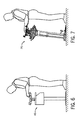
- Figure 6 is a side view of a user in an induced posture while stringing main strings on a racquet.
- Figure 7 is a side view of a user in a preferred posture while stringing main strings on a racquet.
- Figure 8 is a side view of a user in an induced posture while weaving cross strings on a racquet.
- Figure 9 is a side view of a user in a preferred posture while weaving cross strings on a racquet.
- Figure 10 is another perspective view of a racquet stringing machine.
- Figure 11 is a top view of a stringing platform on a racquet stringing machine.
- Figure 12 is a perspective view of a stringing platform.
- Figure 13 is an interior view of a stringing platform.
- Figure 14 is a cross-sectional view of the stringing platform of Figure 12 , taken along line 14-14.
- Figure 15 is a cross-sectional view of a releasable resistance assembly.
- an ergonomically-designed racquet stringing machine is indicated generally at 20.
- the ergonomic features of the stringing machine 20 are intended to provide enhanced comfort for a user during the process of stringing a racquet.
- the stringing machine 20 includes a base 22 configured for supporting the stringing machine 20 on a generally horizontal surface, and a stand 24 having an upper end region 28 and a lower end region 30.
- the lower end region 30 of the stand 24 extends upwardly from a first location 32 on the base 22, and an adjustable stringing platform 26 is coupled to the upper end region 28 of the stand 24 at a second location 34 on the stringing platform 26, as shown in FIG. 3 .
- the "first location" 32 on the base 22 may be defined as the center of the footprint 36 resulting from the attachment of the stand 24 to the base 22.
- the “second location” 34 may be defined as the center of the footprint 38 resulting from the attachment of the stringing platform 26 to the stand 24.
- the "footprint” is a two-dimensional representation of the intersection of two parts that depicts the area of that intersection.
- the first and second locations 32, 34 define a line 40 that is angled by a predetermined angle ( ⁇ ) from horizontal. It is this line 40 to which we refer when discussing the angle ⁇ between the stand 24 and the base 22.
- the stand 24 itself may be curved, such as a "C" shape, or may appear to be bent at one or more locations along its length, but in any case, if the line 40 connecting the first location 32 and the second location 34 defines an angle ⁇ from horizontal within the range defined herein, the stringing machine 20 is still considered to fall within the scope of this invention.
- the stand 24 extends from the base 22 at an angle ⁇ between about 70 and about 89 degrees from a horizontal plane (1 and 20 degrees from a vertical plane), in a direction generally toward the user.
- the angle ⁇ between the stand 24 and the base 22 may be between about 80 and about 85 degrees from a horizontal plane (5 and 10 degrees from a vertical plane), for example 83 degrees from a horizontal plane (7 degrees from a vertical plane).
- conventional stringing machines are configured with a stand that extends perpendicularly from a base. The angled orientation of the stand 24 described in the present invention provides ample legroom for the user standing in front of the stringing machine 20.
- a 7-degree tilt such that the angle ⁇ is 83 degrees from a horizontal plane, provides 40-50 % more legroom compared to a stand 24 that is perpendicular to the base 22.
- the base 22 may be configured to provide a comfortable standing area for the user.
- the base 22 includes a forward side 42 intended to face the user and a rear side 44 opposite the forward side 42. As illustrated in FIGS. 1-3 , the forward side 42 of the base 22 may define a recessed area for accommodating at least a portion of the user's feet, thereby enabling the user to stand closer to the racquet during the stringing process.
- the racquet When stringing a racquet, the racquet must first be clamped onto the adjustable stringing platform 26. As illustrated in FIG. 4 , conventional stringing machines 46 induce poor posture for many users trying to clamp the racquet onto the stringing platform.
- the stand 24 By configuring the stand 24 to extend at a non-perpendicular angle ⁇ between the base 22 and the stand 24 and increasing the height of the stand 24, the user in the desired operating position can stand closer to the stringing platform 26, thereby preventing the user from hunching over the stringing platform 26, as shown in FIG. 5 .
- the height of the stand 24 may either be fixed or adjustable. Any suitable height-adjusting mechanism can be applied to the stringing machine 20, such as a telescoping height-adjustment mechanism.
- the process of stringing the main strings may cause neck strain or other discomfort due to the positioning of the stringing platform with respect to the user's position.
- the positioning of the stringing platform 26 suitably provides a comfortable working area for the user in which the user, in the desired operating position, is able to stand upright in a relatively comfortable position, as shown in FIG. 7 .
- the detail-oriented process of weaving cross strings may also cause neck strain or other discomfort, as exemplified in FIG. 8 .
- the stand 24 By configuring the stand 24 to extend at a non-perpendicular angle ⁇ between the base 22 and the stand 24, the height and angle of the stringing platform 26 can be arranged in a position that allows the user to weave the cross strings in a more ergonomically preferable operating position, as shown in FIG. 9 .
- the base 22 and stand 24 may be a single-leg design, as illustrated in FIGS. 1 and 2 . Alternatively, a two-leg design, as illustrated in FIG. 10 , may work equally well. In any case, the base 22 may be die-cast for added stability.
- the major components of the stringing machine 20, namely the base 22, stand 24, and stringing platform 26, may be formed of metal, wood, plastic, high-strength polymers, composite materials, or any combination of these materials, for example.
- the angle ⁇ between the base 22 and the stand 24 may be permanently fixed, or non-adjustable. In other embodiments, however, the angle ⁇ between the base 22 and the stand 24 may be adjustable.
- a stand adjustment assembly capable of adjusting the angle ⁇ of the line 40 defined by the first and second locations 32, 34 may be coupled to the base 22 and the stand 24. The stand adjustment assembly may be configured to adjust the angle ⁇ of the line 40 within a range of 0.1 to 15.0 degrees.
- the angular adjustment between the base 22 and the stand 24 may be performed either manually or automatically.
- the stand adjustment assembly may include a drive mechanism formed by a chain that runs in a track.
- the drive mechanism may be controlled electronically, for example.
- Those skilled in the art are familiar with a variety of suitable drive mechanisms that would be appropriate for adjusting the angle ⁇ between the base 22 and the stand 24. Therefore, the details of such mechanisms will not be described in detail herein.
- the stringing platform 26 includes multiple frame clamps 48 for maintaining the frame of a racquet in place on the stringing platform 26, and two string clamps 50 for maintaining the strings in place during the stringing process.
- a string tensioning assembly 52 is coupled to the stand 24 atop the stringing platform 26. The string tensioning assembly 52 pulls the strings to the desired tension during the stringing process.
- the stringing platform 26 may either be configured as shown in FIGS. 11 and 12 or, alternatively, may be a conventional stringing platform as found on conventional stringing machines.
- the stringing platform 26 may include a turntable 54 rotatable about a first axis 56, and a first releasable resistance assembly 58, such as a grease brake, coupled to the turntable 54, as shown in FIGS. 11-13 .
- the turntable 54 allows the racquet to spin in a plane in which the frame of the racquet lies.
- the first releasable resistance assembly 58 may be positionable between an engaged operating position in which the resistance assembly 58 resists rotation of the turntable 54 about the first axis 56, and a disengaged operating position in which the resistance assembly 58 does not resist rotation of the turntable 54 about the first axis 56.
- the first releasable resistance assembly 58 can provide resistance to unintentional rotation of the turntable 54.
- the first releasable resistance assembly 58 can negate the effects of gravity when a racquet is in place and the stringing platform 26 is tilted, such as may be caused by the tilted angle of the stand 24.
- the first releasable resistance assembly may provide a resistance against rotation of the turntable (resistance against a torque) about the first axis of within the range of 0.1 to 36 in-lbf, or more preferably within the range of 0.1 to 12.0 in-lbf.
- the first releasable resistance assembly 58 suitably includes a high viscosity fluid, such as a grease, for resisting rotation of the turntable 54 when in the engaged operating position.
- the high viscosity fluid may have a viscosity range of 1 to 500 cP, for example.
- the first releasable resistance assembly 58 includes first and second members 60, 62 contacting the high viscosity fluid, with at least one of the first and second members 60, 62 being rotatable about the first axis 56.
- FIG. 14 is a cross-sectional view of the stringing platform 26, which illustrates the first and second members 60, 62 in the first releasable resistance assembly 58.
- a cross-sectional view of the first releasable resistance assembly 58 is shown in greater detail in FIG. 15 .
- the first and/or second members 60, 62 may include a plurality of projections, such as spaced-apart concentric rings, contacting the fluid.
- each of the first and second members 60, 62 may include a plurality of spaced-apart concentric rings with the rings of the first and second members 60, 62 configured to correspond to each other such that portions of the rings of one of the members fit within the spaces between the rings of the other member.
- the first and second members 60 and 62 can take be formed in other corresponding shapes having different numbers of projections in different orientations.
- the first releasable resistance assembly 58 may also include a latch 64 that releasably engages the first member 60 to prevent the first member 60 from rotating about the first axis 56.
- the latch 64 may be manually operated or remotely operated through a conventional actuation mechanism. In one preferred embodiment, the latch 64 can be used to switch the first resistance assembly 58 between the engaged operating position in which the resistance assembly 58 resists rotation of the turntable 54 about the first axis 56, and a disengaged operating position in which the resistance assembly 58 does not resist rotation of the turntable 54 about the first axis 56.
- the latch 64 When the latch 64 is positioned to engage the first member 60 and to prevent the member 60 from rotating about the first axis 56, the second member 62 remains free to rotate about the first axis 56.
- the second member 62 rotates with respect to the first member 60 and the high viscosity fluid positioned between the corresponding projections of the first and second members 60 and 62 provides resistance to rotation of the second member 62 about the first axis 56.
- a second releasable resistance assembly 66 may also be coupled to the stringing platform 26.
- the turntable 54 may include a ring 68 centered about the first axis 56, and the second releasable resistance assembly 66 may be configured to releasably engage the ring 68 to prevent rotation of the turntable 54 about the first axis 56.
- the mechanism of the second releasable resistance assembly 66 may be similar to a bicycle brake, with a lever operated by the user at one end and the opposite end designed to contact the inner surface of the ring 68 when the brake is applied, thus creating sufficient friction to prevent the turntable 54 from rotating.
- the second releasable resistance assembly 66 releasably locks into position by the user.
- the second releasable resistance assembly 66 is configured to directly stop the turntable 54 from rotating about the first axis 56, including bringing the turntable 54 to a stop in mid-rotation.
- any one or more of the stringing machine embodiments described herein may be applied to machines for stringing tennis racquets, racquetball racquets, squash racquets, badminton racquets, and any other strung racquet.
- the stringing machine 20 may be used to string racquets for use in an organized professional league and/or in competitive play.
- the stringing machine 20 may be configured to string racquets in a manner that meets ITF Rules of Tennis requirements for racquet strings. Regardless of the type of racquet, compatibility of the stringing machine 20 with the user is greatly improved by using any of the stringing machine enhancements in this invention.
Landscapes
- Health & Medical Sciences (AREA)
- General Health & Medical Sciences (AREA)
- Physical Education & Sports Medicine (AREA)
- Pivots And Pivotal Connections (AREA)
- Rolling Contact Bearings (AREA)
- Automatic Assembly (AREA)
- Coiling Of Filamentary Materials In General (AREA)
- Seats For Vehicles (AREA)
Abstract
Description
- Provisional Application Serial No.
60/922,799 filed on April 11, 2007 - The present invention relates to a machine for stringing racquets. This stringing machine has enhanced ergonomic features.
- The act of stringing a racquet requires a considerable amount of manual labor. Stringing machines assist in the process by maintaining the racquet in place and providing desired tension in the strings, but a majority of the work involved is performed by a person. More particularly, a person must align the racquet within the stringing machine, and then string each of the cross or main strings individually, followed by weaving each of the cross and main strings to form the resulting string grid.
- Those in the racquet stringing business often spend many hours a day standing in front of a stringing machine. Conventional stringing machines include a stringing platform with a turntable positioned on top of a fixed stand. The turntable spins within a plane parallel to the floor. Because of the fixed orientation of the stand and the planar position of the turntable, the person stringing the racquet must adjust his or her posture to conform to the position of the stringing machine. In particular, one of the racquet stringer's shoulders is often positioned much higher than the other. Also, the fixed orientation of the stringing machine often induces the racquet stringer to hunch over the turntable. The awkward posture induced by conventional stringing machines often causes injuries and fatigue, which ultimately lead to reduced efficiency in the performance of the racquet stringer. Additionally, conventional stringing machines typically include a vertical stand on a base. The stand and/or base can interfere with the placement of the stringer's feet and/or legs, leading to additional awkwardness in the stringer's posture.
- During the stringing process, the racquet is clamped to the stringing platform and the turntable allows the racquet stringer to manually spin the racquet to adjust the positioning of the racquet with respect to the various steps of the stringing process. Turntables on conventional stringing machines are generally free to spin in response to any applied tangential force unless or until a brake is applied, with the brake preventing any further spinning. If the stringing platform were positioned in the stringing machine such that the turntable spins in a plane non-parallel with the floor, namely tilted toward the racquet stringer, the handle of any racquet clamped to the stringing platform would be drawn by gravity to the lowest point within the plane. Consequently, even though the positioning of the turntable may be more comfortable for the user, the need to either continually move the racquet back into its intended position or continually lock and unlock the brake on the turntable in order to overcome the effects of gravity on the clamped-on racquet would be a nuisance.
- It would thus be desirable to provide a stringing machine that is ergonomically designed to allow users to work with the stringing machine without having to assume awkward or uncomfortable positions, and without having to continuously manually override effects of gravity on the turntable.
- The present invention presents an ergonomically-designed racquet stringing machine for stringing of a racquet by a user. The stringing machine includes a base configured for supporting the stringing machine on a generally horizontal surface, a stand having upper and lower end regions, the lower end region of the stand upwardly extending from a first location of the base, an adjustable stringing platform coupled at a second location to the upper end region of the stand, and a string tensioning assembly coupled to the stand.
- The "first location" of the base may be defined as the center of the footprint resulting from the attachment of the stand to the base. Similarly, the "second location" may be defined as the center of the footprint resulting from the attachment of the stringing platform to the stand. The "footprint" is a two-dimensional representation of the intersection of two parts that depicts the area of that intersection. The first and second locations define a line that is angled by a predetermined angle from horizontal.
- In one embodiment, the stand extends from the base at an angle between about 70 and about 89 degrees from a horizontal plane (1 and 20 degrees from a vertical plane). Alternatively, the angle between the stand and the base may be between about 80 and about 85 degrees from a horizontal plane (5 and 10 degrees from a vertical plane), for example 83 degrees from a horizontal plane (7 degrees from a vertical plane). This angled orientation of the stand provides ample legroom for the user standing in front of the stringing machine. Additionally, a forward side of the base intended to face the user may define a recessed area for accommodating at least a portion of the user's feet thereby enabling the user to stand closer to the racquet during stringing.
- The angle between the base and the stand may be adjustable. For instance, a stand adjustment assembly capable of adjusting the angle of the line defined by the first and second locations may be coupled to the base and the stand. The stand adjustment assembly may be configured to adjust the angle of the line within a range of 0.1 to 15.0 degrees.
- In another embodiment, the adjustable stringing platform may include a turntable rotatable about a first axis, and a first releasable resistance assembly, such as a grease brake, coupled to the turntable. The first releasable resistance assembly may be positionable between an engaged operating position in which the resistance assembly resists rotation of the turntable about the first axis, and a disengaged operating position in which the resistance assembly does not resist rotation of the turntable about the first axis.
- The first releasable resistance assembly can provide resistance to unintentional rotation of the turntable. In particular, the first releasable resistance assembly can negate the effects of gravity when a racquet is in place and the stringing platform is tilted, such as may be caused by the tilted angle of the stand. For example, the first releasable resistance assembly may provide a resistance against rotation of the turntable (resistance against a torque) about the first axis of within the range of 0.1 to 36 in-lbf, or more preferably within the range of 0.1 to 12.0 in-lbf.
- The first releasable resistance assembly suitably includes a high viscosity fluid, such as a grease, for resisting rotation of the turntable when in the engaged operating position. The high viscosity fluid may have a viscosity range of 1 to 500 centipoise (cP), for example. In certain embodiments, the first releasable resistance assembly includes first and second members contacting the high viscosity fluid, with at least one of the first and second members being rotatable about the first axis. The first and/or second members may include a plurality of projections, such as spaced-apart concentric rings, contacting the fluid. For example, each of the first and second members may include a plurality of spaced-apart concentric rings with the rings of the first and second portions configured to correspond to each other such that portions of the rings of one of the members fit within the spaces between the rings of the other member. The first releasable resistance assembly may also include a latch that releasably engages the first member to prevent the first member from rotating about the first axis.
- A second releasable resistance assembly, separate from the first releasable resistance assembly, may also be coupled to the stringing platform. For example, the turntable may include a ring centered about the first axis, and the second releasable resistance assembly may be configured to releasably engage the ring to prevent rotation of the turntable about the first axis.
- Any one or more of the stringing machine embodiments described herein may be applied to machines for stringing tennis racquets, racquetball racquets, squash racquets, badminton racquets, and any other strung racquet. Regardless of the type of racquet, compatibility of the stringing machine with the user is greatly improved by using any of the stringing machine enhancements in this invention.
-
Figure 1 is a perspective view of a racquet stringing machine. -
Figure 2 is a side view of a racquet stringing machine. -
Figure 3 is a schematic view of a racquet stringing machine. -
Figure 4 is a side view of a user in an induced posture while clamping a racquet on a racquet stringing machine. -
Figure 5 is a side view of a user in a preferred posture while clamping a racquet on a racquet stringing machine. -
Figure 6 is a side view of a user in an induced posture while stringing main strings on a racquet. -
Figure 7 is a side view of a user in a preferred posture while stringing main strings on a racquet. -
Figure 8 is a side view of a user in an induced posture while weaving cross strings on a racquet. -
Figure 9 is a side view of a user in a preferred posture while weaving cross strings on a racquet. -
Figure 10 is another perspective view of a racquet stringing machine. -
Figure 11 is a top view of a stringing platform on a racquet stringing machine. -
Figure 12 is a perspective view of a stringing platform. -
Figure 13 is an interior view of a stringing platform. -
Figure 14 is a cross-sectional view of the stringing platform ofFigure 12 , taken along line 14-14. -
Figure 15 is a cross-sectional view of a releasable resistance assembly. - Referring to
FIGS. 1 and2 , an ergonomically-designed racquet stringing machine is indicated generally at 20. The ergonomic features of the stringingmachine 20 are intended to provide enhanced comfort for a user during the process of stringing a racquet. - The stringing
machine 20 includes a base 22 configured for supporting the stringingmachine 20 on a generally horizontal surface, and astand 24 having anupper end region 28 and alower end region 30. Thelower end region 30 of thestand 24 extends upwardly from afirst location 32 on thebase 22, and anadjustable stringing platform 26 is coupled to theupper end region 28 of thestand 24 at asecond location 34 on thestringing platform 26, as shown inFIG. 3 . - The "first location" 32 on the
base 22 may be defined as the center of thefootprint 36 resulting from the attachment of thestand 24 to thebase 22. Similarly, the "second location" 34 may be defined as the center of thefootprint 38 resulting from the attachment of thestringing platform 26 to thestand 24. The "footprint" is a two-dimensional representation of the intersection of two parts that depicts the area of that intersection. The first andsecond locations line 40 that is angled by a predetermined angle (θ) from horizontal. It is thisline 40 to which we refer when discussing the angle θ between thestand 24 and thebase 22. Thestand 24 itself may be curved, such as a "C" shape, or may appear to be bent at one or more locations along its length, but in any case, if theline 40 connecting thefirst location 32 and thesecond location 34 defines an angle θ from horizontal within the range defined herein, the stringingmachine 20 is still considered to fall within the scope of this invention. - In certain embodiments, the
stand 24 extends from the base 22 at an angle θ between about 70 and about 89 degrees from a horizontal plane (1 and 20 degrees from a vertical plane), in a direction generally toward the user. Alternatively, the angle θ between thestand 24 and the base 22 may be between about 80 and about 85 degrees from a horizontal plane (5 and 10 degrees from a vertical plane), for example 83 degrees from a horizontal plane (7 degrees from a vertical plane). In contrast, conventional stringing machines are configured with a stand that extends perpendicularly from a base. The angled orientation of thestand 24 described in the present invention provides ample legroom for the user standing in front of the stringingmachine 20. More particularly, by tilting thestand 24 at an angle θ non-perpendicular to thebase 22, more legroom can be created for the user, thereby allowing the user to stand closer to the stringingmachine 20. For example, a 7-degree tilt, such that the angle θ is 83 degrees from a horizontal plane, provides 40-50 % more legroom compared to astand 24 that is perpendicular to thebase 22. - Additionally, the
base 22 may be configured to provide a comfortable standing area for the user. Thebase 22 includes aforward side 42 intended to face the user and arear side 44 opposite theforward side 42. As illustrated inFIGS. 1-3 , theforward side 42 of the base 22 may define a recessed area for accommodating at least a portion of the user's feet, thereby enabling the user to stand closer to the racquet during the stringing process. - When stringing a racquet, the racquet must first be clamped onto the
adjustable stringing platform 26. As illustrated inFIG. 4 ,conventional stringing machines 46 induce poor posture for many users trying to clamp the racquet onto the stringing platform. By configuring thestand 24 to extend at a non-perpendicular angle θ between the base 22 and thestand 24 and increasing the height of thestand 24, the user in the desired operating position can stand closer to thestringing platform 26, thereby preventing the user from hunching over the stringingplatform 26, as shown inFIG. 5 . The height of thestand 24 may either be fixed or adjustable. Any suitable height-adjusting mechanism can be applied to the stringingmachine 20, such as a telescoping height-adjustment mechanism. - Additional steps in the stringing process also induce poor posture for many users. As shown in
FIG. 6 , the process of stringing the main strings may cause neck strain or other discomfort due to the positioning of the stringing platform with respect to the user's position. Once again, by configuring thestand 24 to extend at a non-perpendicular angle θ between the base 22 and thestand 24 and increasing the height of thestand 24, the positioning of thestringing platform 26 suitably provides a comfortable working area for the user in which the user, in the desired operating position, is able to stand upright in a relatively comfortable position, as shown inFIG. 7 . - Similarly, the detail-oriented process of weaving cross strings may also cause neck strain or other discomfort, as exemplified in
FIG. 8 . By configuring thestand 24 to extend at a non-perpendicular angle θ between the base 22 and thestand 24, the height and angle of thestringing platform 26 can be arranged in a position that allows the user to weave the cross strings in a more ergonomically preferable operating position, as shown inFIG. 9 . - The
base 22 and stand 24 may be a single-leg design, as illustrated inFIGS. 1 and2 . Alternatively, a two-leg design, as illustrated inFIG. 10 , may work equally well. In any case, thebase 22 may be die-cast for added stability. The major components of the stringingmachine 20, namely thebase 22, stand 24, and stringingplatform 26, may be formed of metal, wood, plastic, high-strength polymers, composite materials, or any combination of these materials, for example. - In certain embodiments, the angle θ between the base 22 and the
stand 24 may be permanently fixed, or non-adjustable. In other embodiments, however, the angle θ between the base 22 and thestand 24 may be adjustable. For instance, a stand adjustment assembly capable of adjusting the angle θ of theline 40 defined by the first andsecond locations base 22 and thestand 24. The stand adjustment assembly may be configured to adjust the angle θ of theline 40 within a range of 0.1 to 15.0 degrees. - The angular adjustment between the base 22 and the
stand 24 may be performed either manually or automatically. For example, the stand adjustment assembly may include a drive mechanism formed by a chain that runs in a track. The drive mechanism may be controlled electronically, for example. Those skilled in the art are familiar with a variety of suitable drive mechanisms that would be appropriate for adjusting the angle θ between the base 22 and thestand 24. Therefore, the details of such mechanisms will not be described in detail herein. - As illustrated in
FIG. 11 , the stringingplatform 26 includes multiple frame clamps 48 for maintaining the frame of a racquet in place on thestringing platform 26, and two string clamps 50 for maintaining the strings in place during the stringing process. As shown inFIG. 12 , astring tensioning assembly 52 is coupled to thestand 24 atop the stringingplatform 26. Thestring tensioning assembly 52 pulls the strings to the desired tension during the stringing process. Thestringing platform 26 may either be configured as shown inFIGS. 11 and12 or, alternatively, may be a conventional stringing platform as found on conventional stringing machines. - In certain embodiments, the stringing
platform 26 may include aturntable 54 rotatable about afirst axis 56, and a firstreleasable resistance assembly 58, such as a grease brake, coupled to theturntable 54, as shown inFIGS. 11-13 . Theturntable 54 allows the racquet to spin in a plane in which the frame of the racquet lies. The firstreleasable resistance assembly 58 may be positionable between an engaged operating position in which theresistance assembly 58 resists rotation of theturntable 54 about thefirst axis 56, and a disengaged operating position in which theresistance assembly 58 does not resist rotation of theturntable 54 about thefirst axis 56. - The first
releasable resistance assembly 58 can provide resistance to unintentional rotation of theturntable 54. In particular, the firstreleasable resistance assembly 58 can negate the effects of gravity when a racquet is in place and thestringing platform 26 is tilted, such as may be caused by the tilted angle of thestand 24. For example, the first releasable resistance assembly may provide a resistance against rotation of the turntable (resistance against a torque) about the first axis of within the range of 0.1 to 36 in-lbf, or more preferably within the range of 0.1 to 12.0 in-lbf. - The first
releasable resistance assembly 58 suitably includes a high viscosity fluid, such as a grease, for resisting rotation of theturntable 54 when in the engaged operating position. The high viscosity fluid may have a viscosity range of 1 to 500 cP, for example. By using such a highly viscous lubricant, theturntable 54 can be maintained in place, even when theturntable 54 is lying in a plane non-parallel to the horizontal surface on which the stringingmachine 20 is standing, without the need to mechanically lock theturntable 54 in place. - In certain embodiments, the first
releasable resistance assembly 58 includes first andsecond members second members first axis 56.FIG. 14 is a cross-sectional view of thestringing platform 26, which illustrates the first andsecond members releasable resistance assembly 58. A cross-sectional view of the firstreleasable resistance assembly 58 is shown in greater detail inFIG. 15 . The first and/orsecond members second members second members second members - The first
releasable resistance assembly 58 may also include alatch 64 that releasably engages thefirst member 60 to prevent thefirst member 60 from rotating about thefirst axis 56. Thelatch 64 may be manually operated or remotely operated through a conventional actuation mechanism. In one preferred embodiment, thelatch 64 can be used to switch thefirst resistance assembly 58 between the engaged operating position in which theresistance assembly 58 resists rotation of theturntable 54 about thefirst axis 56, and a disengaged operating position in which theresistance assembly 58 does not resist rotation of theturntable 54 about thefirst axis 56. When thelatch 64 is positioned to engage thefirst member 60 and to prevent themember 60 from rotating about thefirst axis 56, thesecond member 62 remains free to rotate about thefirst axis 56. However, with thefirst member 60 in a locked position, thesecond member 62 rotates with respect to thefirst member 60 and the high viscosity fluid positioned between the corresponding projections of the first andsecond members second member 62 about thefirst axis 56. - As illustrated in
FIG. 13 , a secondreleasable resistance assembly 66, separate from the firstreleasable resistance assembly 58, may also be coupled to thestringing platform 26. For example, as shown inFIG. 11 , theturntable 54 may include aring 68 centered about thefirst axis 56, and the secondreleasable resistance assembly 66 may be configured to releasably engage thering 68 to prevent rotation of theturntable 54 about thefirst axis 56. The mechanism of the secondreleasable resistance assembly 66 may be similar to a bicycle brake, with a lever operated by the user at one end and the opposite end designed to contact the inner surface of thering 68 when the brake is applied, thus creating sufficient friction to prevent theturntable 54 from rotating. Preferably, the secondreleasable resistance assembly 66 releasably locks into position by the user. In contrast with the firstreleasable resistance assembly 58, which merely resists rotation, the secondreleasable resistance assembly 66 is configured to directly stop theturntable 54 from rotating about thefirst axis 56, including bringing theturntable 54 to a stop in mid-rotation. - Any one or more of the stringing machine embodiments described herein may be applied to machines for stringing tennis racquets, racquetball racquets, squash racquets, badminton racquets, and any other strung racquet. In particular, the stringing
machine 20 may be used to string racquets for use in an organized professional league and/or in competitive play. Furthermore, the stringingmachine 20 may be configured to string racquets in a manner that meets ITF Rules of Tennis requirements for racquet strings. Regardless of the type of racquet, compatibility of the stringingmachine 20 with the user is greatly improved by using any of the stringing machine enhancements in this invention. - While the preferred embodiments of the invention have been illustrated and described, it will be appreciated that various changes can be made therein without departing from the spirit and scope of the invention. For example, while the embodiments described herein are illustrated in a stringing machine for stringing a tennis racquet, the principles of the present invention could also be used for stringing machines for stringing practically any other type of racquet. Accordingly, it will be intended to include all such alternatives, modifications and variations set forth within the spirit and scope of the appended claims.
Claims (6)
- A stringing machine, comprising:a base (22);a stand (24) coupled to and upwardly extending from the base (22);an adjustable stringing platform (26) coupled to the stand (24), the stringing platform (26) including a turntable (54) rotatable about a first axis (56), and a first releasable resistance assembly (58) coupled to the turntable, the first releasable resistance assembly (58) being positionable between an engaged operating position in which the releasable resistance assembly (58) resists rotation of the turntable about the first axis (56), and a disengaged operating position in which the releasable resistance assembly (58) does not resist rotation of the turntable about the first axis (56), the releasable resistance assembly (58) including a high viscosity fluid for resisting rotation of the turntable (54) about the first axis (56) when in the engaged operating position.
- The stringing machine of claim 1, further comprising a second releasable resistance assembly (66) coupled to the stringing platform (26), wherein the second releasable resistance assembly (66) is separate from the first releasable resistance assembly (58), and wherein the turntable (54) includes a ring (68) centered about the first axis (56), and wherein the second releasable resistance assembly (66) is configured to releasably engage the ring (68) to prevent rotation of the turntable (54) about the first axis (56).
- The stringing machine of claim 1, wherein the first releasable resistance assembly (58) resists a torque about the first axis within the range of (56) 0.01 to 4 Nm (0.1 to 36 in-lbf), and wherein the resistance force applied by the first releasable resistance assembly is 13.3 N (3 lbs) or less.
- The stringing machine of claim 1, wherein the first releasable resistance assembly includes first and second members (60, 62) contacting the high viscosity fluid, and wherein at least one of the first and second members (60, 62) is rotatable about the first axis (56).
- The stringing machine of claim 4, wherein at least one of the first and second members (60, 62) includes a plurality of projections contacting the fluid.
- The stringing machine of claim 1, wherein the high viscosity fluid has a viscosity range of 1x10⁻³ to 5x10⁻¹ Pas (1 to 500 cP).
Applications Claiming Priority (3)
| Application Number | Priority Date | Filing Date | Title |
|---|---|---|---|
| US92279907P | 2007-04-11 | 2007-04-11 | |
| US12/077,012 US7695383B2 (en) | 2007-04-11 | 2008-03-14 | Racquet stringing machine |
| EP08007151A EP1980298B1 (en) | 2007-04-11 | 2008-04-10 | Racquet stringing machine |
Related Parent Applications (1)
| Application Number | Title | Priority Date | Filing Date |
|---|---|---|---|
| EP08007151.7 Division | 2008-04-10 |
Publications (2)
| Publication Number | Publication Date |
|---|---|
| EP2177248A1 true EP2177248A1 (en) | 2010-04-21 |
| EP2177248B1 EP2177248B1 (en) | 2011-08-17 |
Family
ID=39590926
Family Applications (2)
| Application Number | Title | Priority Date | Filing Date |
|---|---|---|---|
| EP09016101A Ceased EP2177248B1 (en) | 2007-04-11 | 2008-04-10 | Racquet stringing machine |
| EP08007151A Not-in-force EP1980298B1 (en) | 2007-04-11 | 2008-04-10 | Racquet stringing machine |
Family Applications After (1)
| Application Number | Title | Priority Date | Filing Date |
|---|---|---|---|
| EP08007151A Not-in-force EP1980298B1 (en) | 2007-04-11 | 2008-04-10 | Racquet stringing machine |
Country Status (5)
| Country | Link |
|---|---|
| US (1) | US7695383B2 (en) |
| EP (2) | EP2177248B1 (en) |
| JP (1) | JP5507816B2 (en) |
| DE (1) | DE602008001818D1 (en) |
| ES (1) | ES2347495T3 (en) |
Cited By (1)
| Publication number | Priority date | Publication date | Assignee | Title |
|---|---|---|---|---|
| US8066593B2 (en) * | 2007-04-11 | 2011-11-29 | Wilson Sporting Goods Co. | Customized racquet stringing system and method |
Families Citing this family (10)
| Publication number | Priority date | Publication date | Assignee | Title |
|---|---|---|---|---|
| US7695383B2 (en) * | 2007-04-11 | 2010-04-13 | Wilson Sporting Goods Co. | Racquet stringing machine |
| US8075429B2 (en) * | 2007-04-11 | 2011-12-13 | Wilson Sporting Goods Co. | Racquet stringing machine |
| US7833118B2 (en) * | 2007-04-11 | 2010-11-16 | Wilson Sporting Goods Co. | Racquet stringing machine |
| US7686713B2 (en) * | 2007-04-11 | 2010-03-30 | Wilson Sporting Goods Co. | Racquet stringing machine |
| US7980968B1 (en) * | 2010-06-17 | 2011-07-19 | Elding Ind. Co., Ltd. | Stringing device of a racket stringing machine |
| US8206249B1 (en) * | 2011-04-08 | 2012-06-26 | Herbert H. Wise | Electronic racquet stringing machine |
| US9884228B2 (en) * | 2015-09-23 | 2018-02-06 | Chethan Yadav | Racket-stringing machine |
| KR101753713B1 (en) | 2015-10-28 | 2017-07-04 | 김창식 | String working Device for Raket |
| CN107998629A (en) * | 2018-01-30 | 2018-05-08 | 蒋国华 | A kind of racket threading mends line machine |
| USD1114859S1 (en) * | 2024-10-25 | 2026-02-24 | Jose Frank Statham | Racquet mounting equipment |
Citations (3)
| Publication number | Priority date | Publication date | Assignee | Title |
|---|---|---|---|---|
| US2100948A (en) * | 1936-11-25 | 1937-11-30 | Doll Air Stringer Of America I | Apparatus for stringing rackets |
| US3988022A (en) * | 1975-06-04 | 1976-10-26 | Tennis Machines, Inc. | Racket stringing machine |
| US4130278A (en) * | 1977-06-21 | 1978-12-19 | Gutzwiller Robert L | Racquet stringing machine |
Family Cites Families (35)
| Publication number | Priority date | Publication date | Assignee | Title |
|---|---|---|---|---|
| US22740A (en) * | 1859-01-25 | Heating appakattts | ||
| US96160A (en) * | 1869-10-26 | Improvement in sewing-machine | ||
| US2015238A (en) * | 1934-07-30 | 1935-09-24 | Saladino Joseph | Racket string tightening machine |
| US2043813A (en) | 1934-09-04 | 1936-06-09 | Saladino Joseph | Racket string tightening machine |
| DE2915647A1 (en) | 1979-04-18 | 1980-10-30 | Richard Hahn | Tennis racquet stringing machine - has two reciprocal detachable holders located oppositely on either side of frame clamp |
| FR2551352B1 (en) | 1983-08-31 | 1986-05-09 | Morel Jacques | APPARATUS FOR CORDING RACKETS |
| JPS60199475A (en) * | 1984-03-26 | 1985-10-08 | 土田 明 | Gut tensioning apparatus in gut pulling machine of tennis racket |
| US4546977A (en) * | 1984-06-14 | 1985-10-15 | Ektelon | Racquet stringing machine with improved racquet retaining standard |
| US4706955A (en) * | 1986-05-20 | 1987-11-17 | Sumiaty Ngadi | Racket frame clamp for stringing machine |
| FR2642655B1 (en) * | 1989-02-07 | 1993-02-19 | Babolat Vs | APPARATUS FOR STRINGING A TENNIS RACKET |
| US5090697A (en) * | 1991-03-22 | 1992-02-25 | Poreex Industrial Co., Ltd. | Racket frame stringing machine |
| US5186505A (en) * | 1992-03-09 | 1993-02-16 | Chu David T | Chucking device of racket stringing machine |
| US5269515A (en) * | 1993-04-29 | 1993-12-14 | Chu David T | Machine for stringing game racket |
| US5568921A (en) * | 1993-10-26 | 1996-10-29 | Ektelon | Racquet stringing machine |
| US5338028A (en) * | 1993-12-28 | 1994-08-16 | Right Way Co. | Racket stringing apparatus |
| US5820500A (en) * | 1994-05-03 | 1998-10-13 | Raos; Davor | Non-rotating racquet and stringing machine and method |
| US5590877A (en) * | 1996-05-07 | 1997-01-07 | Ho; Ping-Sen | Racket string bracing apparatus |
| US5639086A (en) * | 1996-06-17 | 1997-06-17 | Prince Sports Group Inc | Universal stringing machine for sports racquets |
| US5733212A (en) * | 1996-10-08 | 1998-03-31 | Wise U. S. A., Inc. | Electronic racket stringing machine |
| US5908362A (en) * | 1997-02-11 | 1999-06-01 | Ferrari Importing Company | Tensioning device for stringing sports racquets having a string guide for maintaining constant string line of action to string gripper |
| US6162139A (en) * | 1999-04-26 | 2000-12-19 | Deuce Industries Ltd. | String tensioning device |
| KR200194486Y1 (en) * | 2000-03-10 | 2000-09-01 | 유민선 | String machine for racket |
| JP2001314532A (en) * | 2000-05-02 | 2001-11-13 | Akira Tsuchida | Gut clamp mechanism in gut tensioning equipment such as tennis rackets |
| TW494782U (en) * | 2001-08-03 | 2002-07-11 | Elding Ind Co Ltd | Control device for racket threading machine |
| TW493457U (en) * | 2001-08-10 | 2002-07-01 | Ding-Wei Ju | Device for pulling thread for racket |
| JP3655624B2 (en) | 2002-02-25 | 2005-06-02 | 章史 中根 | Gutting equipment |
| US6764418B1 (en) * | 2003-05-01 | 2004-07-20 | Min-Wei Lee | Stringer of a racket |
| US6837811B1 (en) * | 2004-03-16 | 2005-01-04 | Pao-Chang Wu | String pulling device for racket stringer |
| US7153226B1 (en) * | 2005-12-27 | 2006-12-26 | Erik Bernard Van Der Pols | String-pulling device of a racket stringing apparatus |
| TW200829310A (en) * | 2007-01-09 | 2008-07-16 | zai-tian Li | Height adjustment device for line stretcher head of racket threader |
| JP2008178435A (en) * | 2007-01-23 | 2008-08-07 | Akira Tsuchida | Work table tilting device for gutting machines such as tennis rackets |
| TW200838583A (en) * | 2007-03-30 | 2008-10-01 | zai-tian Li | Height adjustment device of wire strainer for wire pulling head of racket stringing machine |
| US7833118B2 (en) * | 2007-04-11 | 2010-11-16 | Wilson Sporting Goods Co. | Racquet stringing machine |
| US7686713B2 (en) * | 2007-04-11 | 2010-03-30 | Wilson Sporting Goods Co. | Racquet stringing machine |
| US7695383B2 (en) * | 2007-04-11 | 2010-04-13 | Wilson Sporting Goods Co. | Racquet stringing machine |
-
2008
- 2008-03-14 US US12/077,012 patent/US7695383B2/en active Active
- 2008-04-10 EP EP09016101A patent/EP2177248B1/en not_active Ceased
- 2008-04-10 EP EP08007151A patent/EP1980298B1/en not_active Not-in-force
- 2008-04-10 JP JP2008102887A patent/JP5507816B2/en active Active
- 2008-04-10 ES ES08007151T patent/ES2347495T3/en active Active
- 2008-04-10 DE DE602008001818T patent/DE602008001818D1/en active Active
Patent Citations (3)
| Publication number | Priority date | Publication date | Assignee | Title |
|---|---|---|---|---|
| US2100948A (en) * | 1936-11-25 | 1937-11-30 | Doll Air Stringer Of America I | Apparatus for stringing rackets |
| US3988022A (en) * | 1975-06-04 | 1976-10-26 | Tennis Machines, Inc. | Racket stringing machine |
| US4130278A (en) * | 1977-06-21 | 1978-12-19 | Gutzwiller Robert L | Racquet stringing machine |
Cited By (3)
| Publication number | Priority date | Publication date | Assignee | Title |
|---|---|---|---|---|
| US8066593B2 (en) * | 2007-04-11 | 2011-11-29 | Wilson Sporting Goods Co. | Customized racquet stringing system and method |
| US20120277039A1 (en) * | 2007-04-11 | 2012-11-01 | Wilson Sporting Goods Co. | Customized racquet stringing system |
| US8303441B1 (en) * | 2007-04-11 | 2012-11-06 | Wilson Sporting Goods Co. | Customized racquet stringing system |
Also Published As
| Publication number | Publication date |
|---|---|
| EP1980298A3 (en) | 2008-12-31 |
| US7695383B2 (en) | 2010-04-13 |
| JP2008302209A (en) | 2008-12-18 |
| DE602008001818D1 (en) | 2010-09-02 |
| EP1980298B1 (en) | 2010-07-21 |
| ES2347495T3 (en) | 2010-10-29 |
| US20080254924A1 (en) | 2008-10-16 |
| EP1980298A2 (en) | 2008-10-15 |
| JP5507816B2 (en) | 2014-05-28 |
| EP2177248B1 (en) | 2011-08-17 |
Similar Documents
| Publication | Publication Date | Title |
|---|---|---|
| EP2177248B1 (en) | Racquet stringing machine | |
| US6918861B2 (en) | Exerciser having rotatable seat device | |
| US7250022B2 (en) | Exercise device with centrally mounted resistance rod | |
| US5695433A (en) | Variable height body support for exercise apparatus | |
| US5718660A (en) | Exerciser for straightening spinal column | |
| US4961569A (en) | Arm levers for total exercise stationary cycles | |
| US8272999B2 (en) | Seat mechanisms | |
| US7648447B2 (en) | Leg exercise device for use with an office chair | |
| US7874615B2 (en) | Recumbent seat mechanism | |
| CA2627150C (en) | Seat mechanism for adjusting the vertical and horizontal positioning of a bicycle seat | |
| US8012070B2 (en) | Portable mountable upper-body exercise device | |
| US7833118B2 (en) | Racquet stringing machine | |
| KR20150085773A (en) | A sporting apparatus for multi purpose | |
| US10549148B2 (en) | Exercise device | |
| US8167779B2 (en) | Full body twisting exercise machine | |
| US10737131B2 (en) | Triceps press exercise machine with a moving user support | |
| US11491363B2 (en) | Exercise methods and apparatus | |
| US20120238413A1 (en) | Upper and lower body cycling exercise device | |
| US5906562A (en) | Stepping and swinging exerciser | |
| US9227105B2 (en) | Exercise device | |
| US8075429B2 (en) | Racquet stringing machine | |
| CN102188802A (en) | Racket threader |
Legal Events
| Date | Code | Title | Description |
|---|---|---|---|
| PUAI | Public reference made under article 153(3) epc to a published international application that has entered the european phase |
Free format text: ORIGINAL CODE: 0009012 |
|
| 17P | Request for examination filed |
Effective date: 20100115 |
|
| AC | Divisional application: reference to earlier application |
Ref document number: 1980298 Country of ref document: EP Kind code of ref document: P |
|
| AK | Designated contracting states |
Kind code of ref document: A1 Designated state(s): DE ES FR GB |
|
| GRAP | Despatch of communication of intention to grant a patent |
Free format text: ORIGINAL CODE: EPIDOSNIGR1 |
|
| RIC1 | Information provided on ipc code assigned before grant |
Ipc: A63B 51/14 20060101AFI20100929BHEP |
|
| GRAS | Grant fee paid |
Free format text: ORIGINAL CODE: EPIDOSNIGR3 |
|
| GRAA | (expected) grant |
Free format text: ORIGINAL CODE: 0009210 |
|
| AC | Divisional application: reference to earlier application |
Ref document number: 1980298 Country of ref document: EP Kind code of ref document: P |
|
| AK | Designated contracting states |
Kind code of ref document: B1 Designated state(s): DE ES FR GB |
|
| REG | Reference to a national code |
Ref country code: GB Ref legal event code: FG4D |
|
| REG | Reference to a national code |
Ref country code: DE Ref legal event code: R096 Ref document number: 602008009032 Country of ref document: DE Effective date: 20111020 |
|
| PLBE | No opposition filed within time limit |
Free format text: ORIGINAL CODE: 0009261 |
|
| STAA | Information on the status of an ep patent application or granted ep patent |
Free format text: STATUS: NO OPPOSITION FILED WITHIN TIME LIMIT |
|
| 26N | No opposition filed |
Effective date: 20120521 |
|
| REG | Reference to a national code |
Ref country code: DE Ref legal event code: R097 Ref document number: 602008009032 Country of ref document: DE Effective date: 20120521 |
|
| PG25 | Lapsed in a contracting state [announced via postgrant information from national office to epo] |
Ref country code: ES Free format text: LAPSE BECAUSE OF FAILURE TO SUBMIT A TRANSLATION OF THE DESCRIPTION OR TO PAY THE FEE WITHIN THE PRESCRIBED TIME-LIMIT Effective date: 20111128 |
|
| REG | Reference to a national code |
Ref country code: FR Ref legal event code: PLFP Year of fee payment: 9 |
|
| PGFP | Annual fee paid to national office [announced via postgrant information from national office to epo] |
Ref country code: GB Payment date: 20160406 Year of fee payment: 9 |
|
| REG | Reference to a national code |
Ref country code: DE Ref legal event code: R082 Ref document number: 602008009032 Country of ref document: DE Representative=s name: BRANDSTOCK LEGAL RECHTSANWALTGESELLSCHAFT MBH, DE Ref country code: DE Ref legal event code: R082 Ref document number: 602008009032 Country of ref document: DE Representative=s name: BRANDSTOCK LEGAL RECHTSANWALTSGESELLSCHAFT MBH, DE |
|
| REG | Reference to a national code |
Ref country code: FR Ref legal event code: PLFP Year of fee payment: 10 |
|
| GBPC | Gb: european patent ceased through non-payment of renewal fee |
Effective date: 20170410 |
|
| PG25 | Lapsed in a contracting state [announced via postgrant information from national office to epo] |
Ref country code: GB Free format text: LAPSE BECAUSE OF NON-PAYMENT OF DUE FEES Effective date: 20170410 |
|
| REG | Reference to a national code |
Ref country code: FR Ref legal event code: PLFP Year of fee payment: 11 |
|
| PGFP | Annual fee paid to national office [announced via postgrant information from national office to epo] |
Ref country code: FR Payment date: 20240308 Year of fee payment: 17 |
|
| PGFP | Annual fee paid to national office [announced via postgrant information from national office to epo] |
Ref country code: DE Payment date: 20240306 Year of fee payment: 17 |
|
| REG | Reference to a national code |
Ref country code: DE Ref legal event code: R119 Ref document number: 602008009032 Country of ref document: DE |
|
| PG25 | Lapsed in a contracting state [announced via postgrant information from national office to epo] |
Ref country code: DE Free format text: LAPSE BECAUSE OF NON-PAYMENT OF DUE FEES Effective date: 20251104 |
|
| PG25 | Lapsed in a contracting state [announced via postgrant information from national office to epo] |
Ref country code: FR Free format text: LAPSE BECAUSE OF NON-PAYMENT OF DUE FEES Effective date: 20250430 |