EP2176723B1 - Pilot device with remote pressure control for gas pressure regulators - Google Patents
Pilot device with remote pressure control for gas pressure regulators Download PDFInfo
- Publication number
- EP2176723B1 EP2176723B1 EP20080786804 EP08786804A EP2176723B1 EP 2176723 B1 EP2176723 B1 EP 2176723B1 EP 20080786804 EP20080786804 EP 20080786804 EP 08786804 A EP08786804 A EP 08786804A EP 2176723 B1 EP2176723 B1 EP 2176723B1
- Authority
- EP
- European Patent Office
- Prior art keywords
- pressure
- gas
- membrane
- chamber
- pilot device
- Prior art date
- Legal status (The legal status is an assumption and is not a legal conclusion. Google has not performed a legal analysis and makes no representation as to the accuracy of the status listed.)
- Not-in-force
Links
- 239000012528 membrane Substances 0.000 claims abstract description 39
- 238000003475 lamination Methods 0.000 claims description 2
- 239000007789 gas Substances 0.000 description 48
- 230000000694 effects Effects 0.000 description 9
- VNWKTOKETHGBQD-UHFFFAOYSA-N methane Chemical compound C VNWKTOKETHGBQD-UHFFFAOYSA-N 0.000 description 6
- 230000014509 gene expression Effects 0.000 description 4
- 239000003345 natural gas Substances 0.000 description 3
- 230000009471 action Effects 0.000 description 2
- 238000000034 method Methods 0.000 description 2
- 230000009467 reduction Effects 0.000 description 2
- 230000001105 regulatory effect Effects 0.000 description 2
- 230000009286 beneficial effect Effects 0.000 description 1
- 238000004364 calculation method Methods 0.000 description 1
- 230000015556 catabolic process Effects 0.000 description 1
- 230000008859 change Effects 0.000 description 1
- 230000002596 correlated effect Effects 0.000 description 1
- 230000001419 dependent effect Effects 0.000 description 1
- 239000002360 explosive Substances 0.000 description 1
- 239000002737 fuel gas Substances 0.000 description 1
- 238000009434 installation Methods 0.000 description 1
- 230000003993 interaction Effects 0.000 description 1
- 230000007246 mechanism Effects 0.000 description 1
- 230000002277 temperature effect Effects 0.000 description 1
Images

Classifications
-
- G—PHYSICS
- G05—CONTROLLING; REGULATING
- G05D—SYSTEMS FOR CONTROLLING OR REGULATING NON-ELECTRIC VARIABLES
- G05D16/00—Control of fluid pressure
- G05D16/14—Control of fluid pressure with auxiliary non-electric power
- G05D16/16—Control of fluid pressure with auxiliary non-electric power derived from the controlled fluid
- G05D16/163—Control of fluid pressure with auxiliary non-electric power derived from the controlled fluid using membranes within the main valve
-
- Y—GENERAL TAGGING OF NEW TECHNOLOGICAL DEVELOPMENTS; GENERAL TAGGING OF CROSS-SECTIONAL TECHNOLOGIES SPANNING OVER SEVERAL SECTIONS OF THE IPC; TECHNICAL SUBJECTS COVERED BY FORMER USPC CROSS-REFERENCE ART COLLECTIONS [XRACs] AND DIGESTS
- Y10—TECHNICAL SUBJECTS COVERED BY FORMER USPC
- Y10T—TECHNICAL SUBJECTS COVERED BY FORMER US CLASSIFICATION
- Y10T137/00—Fluid handling
- Y10T137/7722—Line condition change responsive valves
- Y10T137/7737—Thermal responsive
-
- Y—GENERAL TAGGING OF NEW TECHNOLOGICAL DEVELOPMENTS; GENERAL TAGGING OF CROSS-SECTIONAL TECHNOLOGIES SPANNING OVER SEVERAL SECTIONS OF THE IPC; TECHNICAL SUBJECTS COVERED BY FORMER USPC CROSS-REFERENCE ART COLLECTIONS [XRACs] AND DIGESTS
- Y10—TECHNICAL SUBJECTS COVERED BY FORMER USPC
- Y10T—TECHNICAL SUBJECTS COVERED BY FORMER US CLASSIFICATION
- Y10T137/00—Fluid handling
- Y10T137/7722—Line condition change responsive valves
- Y10T137/7781—With separate connected fluid reactor surface
- Y10T137/7793—With opening bias [e.g., pressure regulator]
- Y10T137/7797—Bias variable during operation
-
- Y—GENERAL TAGGING OF NEW TECHNOLOGICAL DEVELOPMENTS; GENERAL TAGGING OF CROSS-SECTIONAL TECHNOLOGIES SPANNING OVER SEVERAL SECTIONS OF THE IPC; TECHNICAL SUBJECTS COVERED BY FORMER USPC CROSS-REFERENCE ART COLLECTIONS [XRACs] AND DIGESTS
- Y10—TECHNICAL SUBJECTS COVERED BY FORMER USPC
- Y10T—TECHNICAL SUBJECTS COVERED BY FORMER US CLASSIFICATION
- Y10T137/00—Fluid handling
- Y10T137/7722—Line condition change responsive valves
- Y10T137/7781—With separate connected fluid reactor surface
- Y10T137/7793—With opening bias [e.g., pressure regulator]
- Y10T137/7801—Balanced valve
-
- Y—GENERAL TAGGING OF NEW TECHNOLOGICAL DEVELOPMENTS; GENERAL TAGGING OF CROSS-SECTIONAL TECHNOLOGIES SPANNING OVER SEVERAL SECTIONS OF THE IPC; TECHNICAL SUBJECTS COVERED BY FORMER USPC CROSS-REFERENCE ART COLLECTIONS [XRACs] AND DIGESTS
- Y10—TECHNICAL SUBJECTS COVERED BY FORMER USPC
- Y10T—TECHNICAL SUBJECTS COVERED BY FORMER US CLASSIFICATION
- Y10T137/00—Fluid handling
- Y10T137/7722—Line condition change responsive valves
- Y10T137/7781—With separate connected fluid reactor surface
- Y10T137/7793—With opening bias [e.g., pressure regulator]
- Y10T137/7805—Through external pipe
-
- Y—GENERAL TAGGING OF NEW TECHNOLOGICAL DEVELOPMENTS; GENERAL TAGGING OF CROSS-SECTIONAL TECHNOLOGIES SPANNING OVER SEVERAL SECTIONS OF THE IPC; TECHNICAL SUBJECTS COVERED BY FORMER USPC CROSS-REFERENCE ART COLLECTIONS [XRACs] AND DIGESTS
- Y10—TECHNICAL SUBJECTS COVERED BY FORMER USPC
- Y10T—TECHNICAL SUBJECTS COVERED BY FORMER US CLASSIFICATION
- Y10T137/00—Fluid handling
- Y10T137/7722—Line condition change responsive valves
- Y10T137/7781—With separate connected fluid reactor surface
- Y10T137/7793—With opening bias [e.g., pressure regulator]
- Y10T137/7809—Reactor surface separated by apertured partition
- Y10T137/782—Reactor surface is diaphragm
Definitions
- the present invention concerns a pilot device with remote pressure control for gas pressure regulators used in particular in natural gas distribution systems.
- a gas pressure regulator of known type comprises a valve body which includes a high pressure chamber connected to a gas supply duct and a low pressure chamber connected to a gas outlet duct.
- the gas flows from the high pressure chamber to the low pressure chamber via a communication passage between the two chambers, combined with a movable shutter suitable for regulating the gas flow rate, connected, in turn, to control means.
- the shutter opens the communication passage to increase the outflow of gas, thus increasing the pressure in the outlet duct until it reaches a value near the rated value.
- the above shutter control means comprise a control head inside which there is a membrane that divides the inner volume of the head into two chambers, one upper chamber which receives, via appropriate pipes, the outlet pressure of the regulation valve, and one lower chamber, called in technical jargon motorization chamber, in which the motorization gas arrives at a pressure which, with the shutter not in the closed position, is always higher than that of the upper chamber.
- the pressure of the motorization gas exerts a thrust on the membrane opposing the thrust of the elastic means connected to the membrane and associated with the shutter.
- the gas contained in the motorization chamber flows out via a small hole in the chamber connected to the outlet duct of the regulation valve and therefore into the outlet duct itself.
- the shutter opens, or remains motionless or consequently closes.
- said elements as described above are associated with pilot devices which supply the motorization gas to the motorization chamber.
- the sector uses the term pilot-controlled gas pressure regulators to indicate gas pressure regulators that include a pilot device.
- the flow rate delivered by the gas pressure regulator can be modified accordingly.
- a further use of the pilot-controlled gas pressure regulator, and therefore of the pilot, is that of changing the outlet pressure according to the gas consumption required downstream.
- pilot-controlled gas pressure regulator Another use of a pilot-controlled gas pressure regulator is that of providing initial summary information regarding the flow rate through the pressure regulator, for example in order to balance the networks.
- the flow rate can be modified, again by varying the pressure and/or flow rate of the motorization gas delivered by the pilot.
- the pilots are generally remote-controlled in order to allow operations to be carried out on the gas pressure regulator to obtain one of the above mentioned conditions.
- the pilots can be remote-controlled by means of electric servo mechanisms, or by means of a load pressure sent to a tank associated with the pilot and which interacts with the elastic membrane with which the thrust of the mechanical elastic setting means (helical spring) also interacts.
- the thrust of the load pressure is added to the thrust of the mechanical elastic setting means, therefore substantially varying the setting of the pilot and consequently establishing a new setting for the pressure and/or flow rate of the motorization gas flowing out of the pilot.
- the mechanical elastic setting means guarantee a minimum basic setting; by varying the load pressure in the tank associated with the pilot, it is possible to increase the setting beyond the preceding basic limit.
- Pilots which are remote-controlled by means of a load pressure are widely used for obvious reasons of cost and safety (in any electric servomechanism it is necessary to eliminate any risk of ignition potentially explosive atmospheres due to the presence of the fuel gas).
- pilot device the pilot with remote control associated with tank with load pressure
- control devices for regulation of the load pressure in the tank associated with the pilot, said control devices can break down or there may be an interruption in their external power supply.
- the pilot device undergoes the effects of temperature variation due both to the diurnal temperature range (maximum exposure to sunlight in the day and drop in temperature at night, especially for non-protected outdoor installations), and to particular atmospheric events.
- the main object of the present invention is to produce a pilot device which ensures that the setting value and therefore the safe operating conditions immediately prior to occurrence of a fault and/or interruption of the energy supply by the external source to the system which controls and provides the load pressure of the tank associated with the pilot are kept.
- the invention aims in particular to make the behaviour of the pilot device, and consequently of the gas pressure regulator connected to it, practically independent of the effect of the temperature variation in the event of breakdown of the loading pressure regulation system.
- the pilot device of the invention comprises a tank supplied with a load pressure which acts on the elastic membrane present in the tank, said tank being provided with a membrane wall.
- the basic setting mechanical elastic means also interact with this membrane wall.
- Said membrane wall is shared with a closed compensation chamber kept at atmospheric pressure.
- the non-influence of the temperature variation on the pilot device is very significant also due to the low pressures present in the pilot load tank which can vary from a few dozen mbars to a few hundred mbars.
- the pilot device that is the subject of the invention and is indicated as a whole by 1 is provided with a head 2 consisting of two chambers separated by a first elastic membrane 3; the outlet pressure of the gas pressure regulator, not shown but functionally connected to the pilot device, reaches the upper chamber, indicated by 4, via the hole 41, connected to a pipe also not shown.
- chamber 5 which is the lower chamber of the head 2 is at atmospheric pressure since it communicates with the atmosphere via the hole 51 .
- the membrane 3 remains balanced, having on one side the pressure of the chamber 4, which is the pressure at the gas pressure regulator outlet, and on the other side, i.e. in the chamber 5, the atmospheric pressure, the thrust of which on the first membrane 3 is integrated by the action of an axial unit exerting thrust on said first membrane and indicated as a whole by 6.
- the unit 6 consists of a first block 61 fastened to the membrane 3 and connected to a second block 62 fastened to the second membrane 71.
- the second block 62 includes the lower part of portion 63, while in a central position it has a chamber to house a motorization regulation unit 8 with an inlet 81 connected to a supply pressure deriving from the inlet pressure of the gas pressure regulator, but not necessarily coinciding with it, and an outlet hole 82 which, via a pipe not shown, is connected to the motorization chamber of the head of the gas pressure regulator, also not shown.
- the motorization gas flows out of the outlet hole 82 at a motorization pressure obtained by reducing the supply pressure by means of one or more laminations.
- the motorization gas thus reaches the motorization chamber of the gas pressure regulator control head.
- the second block 62 with the regulation unit 8 is positioned between the second membrane 71 and a third membrane 72 which make said block axially sliding due to the elasticity of said membranes 71 and 72.
- the pilot device is provided with a compensation chamber 10 sealed with respect to the outside and defined at the top by the rigid wall 101, laterally by the cylindrical wall 102 and at the bottom by a further membrane 73.
- a third block 64 is anchored to the further membrane 73, wherein said block emerges on one side in the chamber 10 and, on the other side of the further membrane 73, it emerges at the bottom and is in contact with the mechanical elastic means for the basic setting of the pilot constituted, in the case of the example, by the spring 12.
- the spring 12 is provided with a pre-loading device 13 consisting of an adjusting screw 14 and a disc 15 where the base of the spring 12 rests. Naturally, when the screw 14 is tightened on the thread of the block 16, the disc 15 moves upward and loads the spring 12.
- the thrust of the spring 12 is transmitted to the second block 62 via the third block 64 and the stems 65 and 66.
- a load pressure P 1 is introduced into said tank 11 via the inlet 120, while the atmospheric pressure indicated by P 2 is present in the compensation chamber 10 .
- said compensation chamber 10 is connected to a tank 111 by means of a pipe 110.
- the further membrane 73 is common to the compensation chamber 10 and to the load tank 11.
- the setting of the pilot device i.e. the pressure regulated by the gas pressure regulator in the outlet duct, depends only on the loads So and S T , in fact it varies proportionally to said loads.
- the object of the invention is thus achieved, i.e. drastic reduction in the effect of the temperature variation on the setting value of the pilot device immediately prior to occurrence of a failure in the pilot tank loading pressure control system, with all the resulting beneficial effects.
Landscapes
- Engineering & Computer Science (AREA)
- Physics & Mathematics (AREA)
- Power Engineering (AREA)
- Fluid Mechanics (AREA)
- General Physics & Mathematics (AREA)
- Automation & Control Theory (AREA)
- Control Of Fluid Pressure (AREA)
Abstract
Description
- The present invention concerns a pilot device with remote pressure control for gas pressure regulators used in particular in natural gas distribution systems.
- As is known, when natural gas is extracted from the natural gas fields, it is conveyed to the users by means of suitable transport and distribution systems. To guarantee safety and continuity of gas delivery to the users, the pressure at the users themselves must be maintained as constant as possible irrespective of the variations in the required flow rate and in the feeding pressure at higher value.
- Said conditions are achieved by the use of gas pressure regulators which, supplied with the gas coming from pipelines at a higher pressure, convey gas at a lower and practically constant pressure to the users.
- A gas pressure regulator of known type comprises a valve body which includes a high pressure chamber connected to a gas supply duct and a low pressure chamber connected to a gas outlet duct.
- The gas flows from the high pressure chamber to the low pressure chamber via a communication passage between the two chambers, combined with a movable shutter suitable for regulating the gas flow rate, connected, in turn, to control means.
- When the pressure in the outlet duct drops with respect to the rated value, the shutter opens the communication passage to increase the outflow of gas, thus increasing the pressure in the outlet duct until it reaches a value near the rated value.
- According to one of the known techniques, the above shutter control means comprise a control head inside which there is a membrane that divides the inner volume of the head into two chambers, one upper chamber which receives, via appropriate pipes, the outlet pressure of the regulation valve, and one lower chamber, called in technical jargon motorization chamber, in which the motorization gas arrives at a pressure which, with the shutter not in the closed position, is always higher than that of the upper chamber.
- The pressure of the motorization gas exerts a thrust on the membrane opposing the thrust of the elastic means connected to the membrane and associated with the shutter.
- Furthermore, the gas contained in the motorization chamber flows out via a small hole in the chamber connected to the outlet duct of the regulation valve and therefore into the outlet duct itself.
- According to the pressure in the motorization chamber, the shutter opens, or remains motionless or consequently closes.
- According to the known technique, said elements as described above are associated with pilot devices which supply the motorization gas to the motorization chamber.
- Examples of known pilot devices are given in documents
EP 0 522 434 A1 andFR 2 451 597 A - The assembly of the three parts, i.e. the body, control head and pilot, forms what is commonly called "pivoted pressure regulator" in technical jargon.
- More specifically, the sector uses the term pilot-controlled gas pressure regulators to indicate gas pressure regulators that include a pilot device.
- It is evident that the pressure and/or flow rate of the motorization gas supplied by the pilot commands and controls the gas pressure regulator according to the variations in external variables such as the required flow rate and the pressure in the inlet duct, so as to maintain the outflow pressure constant via appropriate regulation of the pressure and/or flow rate of the motorization gas in the regulator motorization chamber.
- It is also possible to control and/or change the flow rate at the gas pressure regulator outlet, the flow rate depending on an algorithm which correlates the inlet pressure, the pressure downstream of the regulator and the degree of opening of the regulator shutter.
- Therefore, by modifying the pressure and/or flow rate of the motorization gas, which flows out of the pilot and which reaches the motorization chamber of the regulator head, the flow rate delivered by the gas pressure regulator can be modified accordingly.
- A further use of the pilot-controlled gas pressure regulator, and therefore of the pilot, is that of changing the outlet pressure according to the gas consumption required downstream.
- This is also obtained by changing the setting of the pilot and consequently also the pressure and/or flow rate of the motorization gas, which appropriately controls the gas pressure regulator shutter so as to regulate the downstream pressure to the new value.
- Another use of a pilot-controlled gas pressure regulator is that of providing initial summary information regarding the flow rate through the pressure regulator, for example in order to balance the networks.
- In fact, according to the algorithm which correlates the inlet pressure, the pressure downstream of the gas pressure regulator and the degree of opening of the gas pressure regulator shutter, it is possible to identify the flow rate and therefore obtain the required information.
- Naturally, once the flow rate is known, it can be modified, again by varying the pressure and/or flow rate of the motorization gas delivered by the pilot.
- The pilots are generally remote-controlled in order to allow operations to be carried out on the gas pressure regulator to obtain one of the above mentioned conditions.
- The pilots can be remote-controlled by means of electric servo mechanisms, or by means of a load pressure sent to a tank associated with the pilot and which interacts with the elastic membrane with which the thrust of the mechanical elastic setting means (helical spring) also interacts.
- In this way, the thrust of the load pressure is added to the thrust of the mechanical elastic setting means, therefore substantially varying the setting of the pilot and consequently establishing a new setting for the pressure and/or flow rate of the motorization gas flowing out of the pilot.
- In this case the mechanical elastic setting means guarantee a minimum basic setting; by varying the load pressure in the tank associated with the pilot, it is possible to increase the setting beyond the preceding basic limit.
- Pilots which are remote-controlled by means of a load pressure are widely used for obvious reasons of cost and safety (in any electric servomechanism it is necessary to eliminate any risk of ignition potentially explosive atmospheres due to the presence of the fuel gas).
- From now on, the pilot with remote control associated with tank with load pressure will be simply called "pilot device".
- Despite the considerable levels of safety and of reliability of the remote control devices for regulation of the load pressure in the tank associated with the pilot, said control devices can break down or there may be an interruption in their external power supply.
- In this specific case the pilot device undergoes the effects of temperature variation due both to the diurnal temperature range (maximum exposure to sunlight in the day and drop in temperature at night, especially for non-protected outdoor installations), and to particular atmospheric events.
- It is important to bear in mind that while these temperature variations do not affect the basic setting correlated with the mechanical elastic means, they affect the additional thrust deriving from the pressure of the load gas (since it is contained in a closed chamber) and therefore the setting value of the pilot device immediately prior to occurrence of a failure.
- As a result, the setting of the pressure and/or flow rate of the motorization gas supplied to the gas pressure regulator is no longer under control and unsafe conditions can therefore arise in the event of both increase and decrease in the temperature.
- The main object of the present invention is to produce a pilot device which ensures that the setting value and therefore the safe operating conditions immediately prior to occurrence of a fault and/or interruption of the energy supply by the external source to the system which controls and provides the load pressure of the tank associated with the pilot are kept.
- The invention aims in particular to make the behaviour of the pilot device, and consequently of the gas pressure regulator connected to it, practically independent of the effect of the temperature variation in the event of breakdown of the loading pressure regulation system.
- The above object and others which will be better highlighted below, are achieved by a pilot device cooperating with a gas pressure regulator, the main characteristics of which are in accordance with the contents of the first claim. Further detail characteristics of the pilot device of the invention are described in the dependent claims.
- More precisely, the pilot device of the invention comprises a tank supplied with a load pressure which acts on the elastic membrane present in the tank, said tank being provided with a membrane wall.
- The basic setting mechanical elastic means also interact with this membrane wall.
- Said membrane wall is shared with a closed compensation chamber kept at atmospheric pressure.
- As will be illustrated below, the variation in the thrust exerted on the elastic membrane due to the variation in temperature is practically annulled due to the effect of the compensation chamber.
- The non-influence of the temperature variation on the pilot device is very significant also due to the low pressures present in the pilot load tank which can vary from a few dozen mbars to a few hundred mbars.
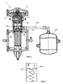
- Further characteristics and particular features of the invention will be better highlighted in the description of the preferred embodiment of the pilot device carried out according to the invention, provided by way of non-limiting example and illustrated in the following drawings, wherein:
-
Figure 1 shows a cross section of the pilot device carried out according to the invention; -
Figure 2 shows a further cross section of the pilot device of the invention connected to an additional tank; -
Figure 3 is a schematic drawing which shows the interaction between pilot tank and compensation chamber. - As can be seen in
Figure 1 , the pilot device that is the subject of the invention and is indicated as a whole by 1 is provided with ahead 2 consisting of two chambers separated by a firstelastic membrane 3; the outlet pressure of the gas pressure regulator, not shown but functionally connected to the pilot device, reaches the upper chamber, indicated by 4, via thehole 41, connected to a pipe also not shown. - While the downstream pressure at the gas pressure regulator outlet is established in
chamber 4,chamber 5, which is the lower chamber of thehead 2, is at atmospheric pressure since it communicates with the atmosphere via thehole 51. - As can be easily seen, the
membrane 3 remains balanced, having on one side the pressure of thechamber 4, which is the pressure at the gas pressure regulator outlet, and on the other side, i.e. in thechamber 5, the atmospheric pressure, the thrust of which on thefirst membrane 3 is integrated by the action of an axial unit exerting thrust on said first membrane and indicated as a whole by 6. - The
unit 6 consists of afirst block 61 fastened to themembrane 3 and connected to asecond block 62 fastened to thesecond membrane 71. - The
second block 62 includes the lower part ofportion 63, while in a central position it has a chamber to house amotorization regulation unit 8 with aninlet 81 connected to a supply pressure deriving from the inlet pressure of the gas pressure regulator, but not necessarily coinciding with it, and anoutlet hole 82 which, via a pipe not shown, is connected to the motorization chamber of the head of the gas pressure regulator, also not shown. - The motorization gas flows out of the
outlet hole 82 at a motorization pressure obtained by reducing the supply pressure by means of one or more laminations. The motorization gas thus reaches the motorization chamber of the gas pressure regulator control head. - The
second block 62 with theregulation unit 8 is positioned between thesecond membrane 71 and athird membrane 72 which make said block axially sliding due to the elasticity of saidmembranes - Under the
third membrane 72 there is anintermediate chamber 9 communicating directly with the atmosphere via thehole 91. - Under said
chamber 9, the pilot device is provided with acompensation chamber 10 sealed with respect to the outside and defined at the top by therigid wall 101, laterally by thecylindrical wall 102 and at the bottom by afurther membrane 73. - A
third block 64 is anchored to thefurther membrane 73, wherein said block emerges on one side in thechamber 10 and, on the other side of thefurther membrane 73, it emerges at the bottom and is in contact with the mechanical elastic means for the basic setting of the pilot constituted, in the case of the example, by thespring 12. - The
spring 12 is provided with apre-loading device 13 consisting of an adjustingscrew 14 and adisc 15 where the base of thespring 12 rests. Naturally, when thescrew 14 is tightened on the thread of theblock 16, thedisc 15 moves upward and loads thespring 12. - The thrust of the
spring 12 is transmitted to thesecond block 62 via thethird block 64 and thestems - As can be seen in
Figure 1 , under thecompensation chamber 10 there is atank 11 which contains thespring 12. - A load pressure P1 is introduced into said
tank 11 via theinlet 120, while the atmospheric pressure indicated by P2 is present in thecompensation chamber 10. - In order to ensure comparable volumes for the
loading chamber 11 and thecompensation chamber 10 and therefore similar thermal inertia, saidcompensation chamber 10 is connected to atank 111 by means of apipe 110. The presence of thetank 111 connected to thecompensation chamber 10, though not being strictly necessary, actually increases the volume of the compensation chamber, consequently ensuring insensitiveness to temperature variations and to other problems such as external micro-leaks of gas. - As can be seen in
Figure 1 , thefurther membrane 73 is common to thecompensation chamber 10 and to theload tank 11. - This particular arrangement of the
chambers further membrane 73 in common, but with different pressure in said chambers, i.e. with pressure P1 higher than the atmospheric pressure P2 of thecompensation chamber 10, minimises the effects of the temperature difference to which the pilot device is subjected in the event of a failure of the loading pressure regulation system. - In said case the negative effects of the temperature variation would necessarily be reflected on the setting of the pilot device in a wholly uncontrolled manner, i.e. only as a result of temperature variations with the obvious risk of affecting the safety conditions.
- To better highlight the effect of the closed
volume compensation chamber 10 maintained at atmospheric pressure on the setting of the pilot in the event of thermal variation, we will use the schematicFigure 3 and some calculation expressions that better show the results achieved with the invention. - With reference to
Figure 3 : - P1 = absolute pressure in
tank 11 at initial reference temperature To - P2 = absolute pressure in
compensation chamber 10 at initial temperature To - P1T = absolute pressure in
tank 11 at temperature T - P2T = absolute pressure in compensation chamber at temperature T
- A = thrust surface area of
further membrane 73. - The thrust exerted on the surface area A at temperature To will be the sum of the thrust exerted by the spring SM and the pressure of the two chambers on the surface A i.e.


- It should be noted that the setting of the pilot device, i.e. the pressure regulated by the gas pressure regulator in the outlet duct, depends only on the loads So and ST , in fact it varies proportionally to said loads.
- Therefore with the
compensation chamber 10, the difference of the total thrust action on the surface A will be given by the expression

- The pressure P2, as we have said, is equal to the atmospheric pressure, so that we can write P2 = Patm, while the pressure P1 is equal to the load pressure increased by the atmospheric pressure, i.e. P1 = Pc + Patm.
- The thrust variation difference ΔSc with compensation chamber, due to the temperature variation, will therefore be

- In order to better highlight the effects of the invention, i.e. of the presence of the
compensation chamber 10, we will now calculate the same thrust variation without the presence of thecompensation chamber 10, i.e. according to the known art. - In said case, the thrust on the surface A at temperature To will be

- At temperature T we will have

- Note that while

closed volume 11, the pressure P2 at the temperature To, and also at the temperature T, remains the same in the absence of a closed volume, said pressure being always equal to the atmospheric pressure, hence
- Consequently, the thrust variation ΔSa, without the compensation chamber, will be


- If we now compare the two expressions ΔSc and ΔSa , i.e. the thrust variation with the compensation chamber and without the compensation chamber, it can be seen that the difference between the two expressions consists in the entity Pc with the compensation chamber and in the entity Pc + Patm without the compensation chamber.
- Since the pressure Pc is a fraction of the atmospheric pressure, generally from a few dozen mbars to a few hundred mbars, assuming for example Pc = 50 mbars we have the value Pc = 0.050 bars while the value Pc + Patm = 0.05 + 1=1.05 bars, assuming an atmospheric pressure of 1 bar abs.
- The above clearly shows that the reduction ratio of the temperature effect between a pilot device with compensation chamber at atmospheric pressure and without compensation chamber is 0.050 : 1.050 i.e. over at least 21 times less.
- With Pc = 250 mbars the effect of the temperature would be 5 times less.
- The object of the invention is thus achieved, i.e. drastic reduction in the effect of the temperature variation on the setting value of the pilot device immediately prior to occurrence of a failure in the pilot tank loading pressure control system, with all the resulting beneficial effects.
Claims (6)
- Pilot device (1) suited to cooperate with a gas pressure regulator suitable for use in gas distribution systems, said gas pressure regulator having high pressure at the inlet and low pressure at the outlet,
said pilot device consisting of:- a head (2) having two chambers (4, 5) separated by a first membrane (3), the upper chamber (4) being at the outlet pressure of said gas pressure regulator and the lower chamber (5) being at the atmospheric pressure;- a body provided with mechanical elastic setting means (12) connected to an axial thrust unit (6) acting on said first membrane (3) and cooperating with a regulation unit (8) having at the inlet (81) a supply pressure which, via one or more laminations, provides at the output (82) the motorization gas at an appropriate pressure and flow rate, said gas being transferred into ducts connected to the motorization chamber of said gas pressure regulator,said pilot device featuring a tank (11) having a wall with a further membrane (73) provided with said mechanical elastic setting means, gas being conveyed to said tank (11) with a load pressure (P1) such as to modify the thrust of said mechanical setting means on said axial thrust unit (6),
characterized in that it is provided with a closed compensation chamber (10) having in common with said tank said further membrane (73). - Pilot device according to claim 1), characterized in that said compensation chamber (10) is connected by means of a pipe (110) to an additional closed tank (111).
- Pilot device according to claim 1) or 2), characterized in that between said head (2) and said compensation chamber (10) there is an intermediate chamber (9) communicating with the free atmosphere.
- Pilot device according to one of the preceding claims, characterized in that said motorization regulation unit (8) is pneumatically isolated from the head (2) and from the intermediate chamber (9) by means of a second membrane (71) near to said head (2) and of a third membrane (72) near to said intermediate chamber (9).
- Pilot device according to claim 4), characterized in that said axial thrust unit (6) consists of:- a first block (61) connected to said second membrane (71) of said head and joined to- a second block (62) between said second membrane (71) and- said third membrane (72);- a third block (64) incorporating said further membrane (73), said third block and said second block being axially connected by means of at least one stem (65, 66).
- Pilot device according to any one of the preceding claims, characterized in that it is provided with a device (13) for pre-loading the mechanical elastic setting means (12), said device (13) having an adjusting screw (14) and a disc (15) on which said elastic means (12) rest.
Applications Claiming Priority (2)
| Application Number | Priority Date | Filing Date | Title |
|---|---|---|---|
| IT000218A ITVI20070218A1 (en) | 2007-08-03 | 2007-08-03 | PILOT DEVICE WITH PRESSURE SWITCH CONTROL FOR GAS PRESSURE REGULATORS |
| PCT/EP2008/060189 WO2009019237A1 (en) | 2007-08-03 | 2008-08-01 | Pilot device with remote pressure control for gas pressure regulators |
Publications (2)
| Publication Number | Publication Date |
|---|---|
| EP2176723A1 EP2176723A1 (en) | 2010-04-21 |
| EP2176723B1 true EP2176723B1 (en) | 2012-03-07 |
Family
ID=39884465
Family Applications (1)
| Application Number | Title | Priority Date | Filing Date |
|---|---|---|---|
| EP20080786804 Not-in-force EP2176723B1 (en) | 2007-08-03 | 2008-08-01 | Pilot device with remote pressure control for gas pressure regulators |
Country Status (5)
| Country | Link |
|---|---|
| US (1) | US8371329B2 (en) |
| EP (1) | EP2176723B1 (en) |
| AT (1) | ATE548685T1 (en) |
| IT (1) | ITVI20070218A1 (en) |
| WO (1) | WO2009019237A1 (en) |
Cited By (1)
| Publication number | Priority date | Publication date | Assignee | Title |
|---|---|---|---|---|
| IT201900009771A1 (en) * | 2019-06-21 | 2020-12-21 | Pietro Fiorentini Spa | PILOT DEVICE FOR THE PILOTING OF PRESSURE REGULATORS FOR GAS DISTRIBUTION SYSTEMS |
Families Citing this family (2)
| Publication number | Priority date | Publication date | Assignee | Title |
|---|---|---|---|---|
| IT201700006901A1 (en) * | 2017-01-23 | 2018-07-23 | Pietro Fiorentini Spa | METHOD FOR MONITORING A GAS FLOW ADJUSTMENT DEVICE AND REGULATING SYSTEM USING THIS METHOD |
| BR112021005693B1 (en) | 2018-09-25 | 2024-02-06 | Hendrickson Usa, L.L.C. | REGULATOR FOR ESTABLISHING OUTPUT FLUID PRESSURE, LOAD-BASED TIRE INFLATION SYSTEM FOR A HEAVY VEHICLE, AND METHOD FOR ESTABLISHING PRESSURE IN AT LEAST ONE TIRE USED ON A HEAVY VEHICLE |
Family Cites Families (10)
| Publication number | Priority date | Publication date | Assignee | Title |
|---|---|---|---|---|
| US1745256A (en) * | 1926-05-14 | 1930-01-28 | Jacob C Groble | Full automatic demand fluid-pressure regulator |
| US2261364A (en) * | 1938-08-29 | 1941-11-04 | Marvin H Grove | Fluid flow controlling apparatus |
| US2833303A (en) * | 1953-01-22 | 1958-05-06 | American Air Filter Co | Control and pressure regulating valve |
| FR2451597A1 (en) | 1979-03-13 | 1980-10-10 | Flonic Sa | Control of pressure for principal regulator - uses membrane in pilot regulator to operate pressure exhaust valve, and has spherical or conical seat adapted to pilot valve |
| DE4103769C1 (en) * | 1991-02-08 | 1992-06-17 | Draegerwerk Ag, 2400 Luebeck, De | |
| IT1253106B (en) | 1991-07-04 | 1995-07-10 | Pietro Fiorentini Spa | PRESSURE REGULATOR FOR GAS. |
| US5423342A (en) * | 1993-05-11 | 1995-06-13 | Fenner, Jr.; Thomas C. | Temperature compensating pressure regulator |
| US5595209A (en) * | 1995-03-29 | 1997-01-21 | Airtrol Components Inc. | Fluid pressure regulator establishing a stable output fluid pressure |
| FR2786865B1 (en) * | 1998-12-02 | 2001-01-12 | Gaz De Petrole | METHOD AND DEVICE FOR MEASURING A QUANTITY OF GAS COMING OUT OF A TANK |
| US7578310B2 (en) * | 2006-05-11 | 2009-08-25 | Delaney Machinerie Inc. | Pressure controller device |
-
2007
- 2007-08-03 IT IT000218A patent/ITVI20070218A1/en unknown
-
2008
- 2008-08-01 EP EP20080786804 patent/EP2176723B1/en not_active Not-in-force
- 2008-08-01 WO PCT/EP2008/060189 patent/WO2009019237A1/en not_active Ceased
- 2008-08-01 US US12/671,540 patent/US8371329B2/en not_active Expired - Fee Related
- 2008-08-01 AT AT08786804T patent/ATE548685T1/en active
Cited By (1)
| Publication number | Priority date | Publication date | Assignee | Title |
|---|---|---|---|---|
| IT201900009771A1 (en) * | 2019-06-21 | 2020-12-21 | Pietro Fiorentini Spa | PILOT DEVICE FOR THE PILOTING OF PRESSURE REGULATORS FOR GAS DISTRIBUTION SYSTEMS |
Also Published As
| Publication number | Publication date |
|---|---|
| WO2009019237A1 (en) | 2009-02-12 |
| US8371329B2 (en) | 2013-02-12 |
| ATE548685T1 (en) | 2012-03-15 |
| US20100155631A1 (en) | 2010-06-24 |
| EP2176723A1 (en) | 2010-04-21 |
| ITVI20070218A1 (en) | 2009-02-04 |
Similar Documents
| Publication | Publication Date | Title |
|---|---|---|
| US11733722B2 (en) | Adjustable deadband control system | |
| US8240327B2 (en) | Pressure loaded service regulator with pressure balanced trim | |
| US9897258B2 (en) | Gas pressure regulator and method for piloting said pressure regulator | |
| JP2019075142A (en) | Pilot-operated regulator with balanced port | |
| EP3497533B1 (en) | Removable balanced regulator | |
| EP1907736B1 (en) | Electromechanical regulator with primary and backup modes of operation for regulating passenger oxygen | |
| US6595237B2 (en) | Pressure regulator for gas transport and distribution plants | |
| US8371329B2 (en) | Pilot device with remote pressure control for gas pressure regulators | |
| US3477462A (en) | High capacity pressure regulated gas diaphragm valve | |
| EP0522434A1 (en) | Pressure regulator for gas | |
| US12264785B2 (en) | Gas control system and method with bracketed deadband | |
| JPH04297906A (en) | Fluid pressure controller | |
| CN109340446B (en) | Indirect acting voltage regulator | |
| US20220187857A1 (en) | Control system for regulating waterworks pressure |
Legal Events
| Date | Code | Title | Description |
|---|---|---|---|
| PUAI | Public reference made under article 153(3) epc to a published international application that has entered the european phase |
Free format text: ORIGINAL CODE: 0009012 |
|
| 17P | Request for examination filed |
Effective date: 20100303 |
|
| AK | Designated contracting states |
Kind code of ref document: A1 Designated state(s): AT BE BG CH CY CZ DE DK EE ES FI FR GB GR HR HU IE IS IT LI LT LU LV MC MT NL NO PL PT RO SE SI SK TR |
|
| AX | Request for extension of the european patent |
Extension state: AL BA MK RS |
|
| DAX | Request for extension of the european patent (deleted) | ||
| GRAP | Despatch of communication of intention to grant a patent |
Free format text: ORIGINAL CODE: EPIDOSNIGR1 |
|
| RIN1 | Information on inventor provided before grant (corrected) |
Inventor name: BERNARDI, MICHELE |
|
| GRAS | Grant fee paid |
Free format text: ORIGINAL CODE: EPIDOSNIGR3 |
|
| GRAA | (expected) grant |
Free format text: ORIGINAL CODE: 0009210 |
|
| AK | Designated contracting states |
Kind code of ref document: B1 Designated state(s): AT BE BG CH CY CZ DE DK EE ES FI FR GB GR HR HU IE IS IT LI LT LU LV MC MT NL NO PL PT RO SE SI SK TR |
|
| REG | Reference to a national code |
Ref country code: GB Ref legal event code: FG4D |
|
| RIN1 | Information on inventor provided before grant (corrected) |
Inventor name: BERNARDI, MICHELE |
|
| REG | Reference to a national code |
Ref country code: AT Ref legal event code: REF Ref document number: 548685 Country of ref document: AT Kind code of ref document: T Effective date: 20120315 Ref country code: CH Ref legal event code: EP |
|
| REG | Reference to a national code |
Ref country code: IE Ref legal event code: FG4D |
|
| REG | Reference to a national code |
Ref country code: DE Ref legal event code: R096 Ref document number: 602008013991 Country of ref document: DE Effective date: 20120503 |
|
| REG | Reference to a national code |
Ref country code: RO Ref legal event code: EPE |
|
| REG | Reference to a national code |
Ref country code: NL Ref legal event code: T3 |
|
| PG25 | Lapsed in a contracting state [announced via postgrant information from national office to epo] |
Ref country code: LT Free format text: LAPSE BECAUSE OF FAILURE TO SUBMIT A TRANSLATION OF THE DESCRIPTION OR TO PAY THE FEE WITHIN THE PRESCRIBED TIME-LIMIT Effective date: 20120307 Ref country code: HR Free format text: LAPSE BECAUSE OF FAILURE TO SUBMIT A TRANSLATION OF THE DESCRIPTION OR TO PAY THE FEE WITHIN THE PRESCRIBED TIME-LIMIT Effective date: 20120307 Ref country code: NO Free format text: LAPSE BECAUSE OF FAILURE TO SUBMIT A TRANSLATION OF THE DESCRIPTION OR TO PAY THE FEE WITHIN THE PRESCRIBED TIME-LIMIT Effective date: 20120607 |
|
| LTIE | Lt: invalidation of european patent or patent extension |
Effective date: 20120307 |
|
| PG25 | Lapsed in a contracting state [announced via postgrant information from national office to epo] |
Ref country code: LV Free format text: LAPSE BECAUSE OF FAILURE TO SUBMIT A TRANSLATION OF THE DESCRIPTION OR TO PAY THE FEE WITHIN THE PRESCRIBED TIME-LIMIT Effective date: 20120307 Ref country code: GR Free format text: LAPSE BECAUSE OF FAILURE TO SUBMIT A TRANSLATION OF THE DESCRIPTION OR TO PAY THE FEE WITHIN THE PRESCRIBED TIME-LIMIT Effective date: 20120608 Ref country code: FI Free format text: LAPSE BECAUSE OF FAILURE TO SUBMIT A TRANSLATION OF THE DESCRIPTION OR TO PAY THE FEE WITHIN THE PRESCRIBED TIME-LIMIT Effective date: 20120307 |
|
| PG25 | Lapsed in a contracting state [announced via postgrant information from national office to epo] |
Ref country code: CY Free format text: LAPSE BECAUSE OF FAILURE TO SUBMIT A TRANSLATION OF THE DESCRIPTION OR TO PAY THE FEE WITHIN THE PRESCRIBED TIME-LIMIT Effective date: 20120307 |
|
| PG25 | Lapsed in a contracting state [announced via postgrant information from national office to epo] |
Ref country code: SE Free format text: LAPSE BECAUSE OF FAILURE TO SUBMIT A TRANSLATION OF THE DESCRIPTION OR TO PAY THE FEE WITHIN THE PRESCRIBED TIME-LIMIT Effective date: 20120307 Ref country code: IS Free format text: LAPSE BECAUSE OF FAILURE TO SUBMIT A TRANSLATION OF THE DESCRIPTION OR TO PAY THE FEE WITHIN THE PRESCRIBED TIME-LIMIT Effective date: 20120707 Ref country code: CZ Free format text: LAPSE BECAUSE OF FAILURE TO SUBMIT A TRANSLATION OF THE DESCRIPTION OR TO PAY THE FEE WITHIN THE PRESCRIBED TIME-LIMIT Effective date: 20120307 Ref country code: SI Free format text: LAPSE BECAUSE OF FAILURE TO SUBMIT A TRANSLATION OF THE DESCRIPTION OR TO PAY THE FEE WITHIN THE PRESCRIBED TIME-LIMIT Effective date: 20120307 Ref country code: PL Free format text: LAPSE BECAUSE OF FAILURE TO SUBMIT A TRANSLATION OF THE DESCRIPTION OR TO PAY THE FEE WITHIN THE PRESCRIBED TIME-LIMIT Effective date: 20120307 Ref country code: BE Free format text: LAPSE BECAUSE OF FAILURE TO SUBMIT A TRANSLATION OF THE DESCRIPTION OR TO PAY THE FEE WITHIN THE PRESCRIBED TIME-LIMIT Effective date: 20120307 Ref country code: EE Free format text: LAPSE BECAUSE OF FAILURE TO SUBMIT A TRANSLATION OF THE DESCRIPTION OR TO PAY THE FEE WITHIN THE PRESCRIBED TIME-LIMIT Effective date: 20120307 |
|
| PG25 | Lapsed in a contracting state [announced via postgrant information from national office to epo] |
Ref country code: SK Free format text: LAPSE BECAUSE OF FAILURE TO SUBMIT A TRANSLATION OF THE DESCRIPTION OR TO PAY THE FEE WITHIN THE PRESCRIBED TIME-LIMIT Effective date: 20120307 Ref country code: PT Free format text: LAPSE BECAUSE OF FAILURE TO SUBMIT A TRANSLATION OF THE DESCRIPTION OR TO PAY THE FEE WITHIN THE PRESCRIBED TIME-LIMIT Effective date: 20120709 |
|
| PLBE | No opposition filed within time limit |
Free format text: ORIGINAL CODE: 0009261 |
|
| STAA | Information on the status of an ep patent application or granted ep patent |
Free format text: STATUS: NO OPPOSITION FILED WITHIN TIME LIMIT |
|
| PG25 | Lapsed in a contracting state [announced via postgrant information from national office to epo] |
Ref country code: DK Free format text: LAPSE BECAUSE OF FAILURE TO SUBMIT A TRANSLATION OF THE DESCRIPTION OR TO PAY THE FEE WITHIN THE PRESCRIBED TIME-LIMIT Effective date: 20120307 |
|
| 26N | No opposition filed |
Effective date: 20121210 |
|
| REG | Reference to a national code |
Ref country code: CH Ref legal event code: PL |
|
| PG25 | Lapsed in a contracting state [announced via postgrant information from national office to epo] |
Ref country code: MC Free format text: LAPSE BECAUSE OF NON-PAYMENT OF DUE FEES Effective date: 20120831 |
|
| REG | Reference to a national code |
Ref country code: DE Ref legal event code: R097 Ref document number: 602008013991 Country of ref document: DE Effective date: 20121210 |
|
| PG25 | Lapsed in a contracting state [announced via postgrant information from national office to epo] |
Ref country code: LI Free format text: LAPSE BECAUSE OF NON-PAYMENT OF DUE FEES Effective date: 20120831 Ref country code: CH Free format text: LAPSE BECAUSE OF NON-PAYMENT OF DUE FEES Effective date: 20120831 Ref country code: ES Free format text: LAPSE BECAUSE OF FAILURE TO SUBMIT A TRANSLATION OF THE DESCRIPTION OR TO PAY THE FEE WITHIN THE PRESCRIBED TIME-LIMIT Effective date: 20120618 |
|
| REG | Reference to a national code |
Ref country code: FR Ref legal event code: ST Effective date: 20130430 |
|
| REG | Reference to a national code |
Ref country code: IE Ref legal event code: MM4A |
|
| PG25 | Lapsed in a contracting state [announced via postgrant information from national office to epo] |
Ref country code: IE Free format text: LAPSE BECAUSE OF NON-PAYMENT OF DUE FEES Effective date: 20120801 Ref country code: BG Free format text: LAPSE BECAUSE OF FAILURE TO SUBMIT A TRANSLATION OF THE DESCRIPTION OR TO PAY THE FEE WITHIN THE PRESCRIBED TIME-LIMIT Effective date: 20120607 |
|
| PG25 | Lapsed in a contracting state [announced via postgrant information from national office to epo] |
Ref country code: FR Free format text: LAPSE BECAUSE OF NON-PAYMENT OF DUE FEES Effective date: 20120831 |
|
| PG25 | Lapsed in a contracting state [announced via postgrant information from national office to epo] |
Ref country code: MT Free format text: LAPSE BECAUSE OF FAILURE TO SUBMIT A TRANSLATION OF THE DESCRIPTION OR TO PAY THE FEE WITHIN THE PRESCRIBED TIME-LIMIT Effective date: 20120307 |
|
| PG25 | Lapsed in a contracting state [announced via postgrant information from national office to epo] |
Ref country code: TR Free format text: LAPSE BECAUSE OF FAILURE TO SUBMIT A TRANSLATION OF THE DESCRIPTION OR TO PAY THE FEE WITHIN THE PRESCRIBED TIME-LIMIT Effective date: 20120307 |
|
| PG25 | Lapsed in a contracting state [announced via postgrant information from national office to epo] |
Ref country code: LU Free format text: LAPSE BECAUSE OF NON-PAYMENT OF DUE FEES Effective date: 20120801 |
|
| PG25 | Lapsed in a contracting state [announced via postgrant information from national office to epo] |
Ref country code: HU Free format text: LAPSE BECAUSE OF FAILURE TO SUBMIT A TRANSLATION OF THE DESCRIPTION OR TO PAY THE FEE WITHIN THE PRESCRIBED TIME-LIMIT Effective date: 20080801 |
|
| PGFP | Annual fee paid to national office [announced via postgrant information from national office to epo] |
Ref country code: IT Payment date: 20220621 Year of fee payment: 15 |
|
| PGFP | Annual fee paid to national office [announced via postgrant information from national office to epo] |
Ref country code: NL Payment date: 20220822 Year of fee payment: 15 |
|
| PGFP | Annual fee paid to national office [announced via postgrant information from national office to epo] |
Ref country code: RO Payment date: 20220722 Year of fee payment: 15 Ref country code: GB Payment date: 20220822 Year of fee payment: 15 Ref country code: DE Payment date: 20220819 Year of fee payment: 15 Ref country code: AT Payment date: 20220822 Year of fee payment: 15 |
|
| REG | Reference to a national code |
Ref country code: DE Ref legal event code: R119 Ref document number: 602008013991 Country of ref document: DE |
|
| REG | Reference to a national code |
Ref country code: NL Ref legal event code: MM Effective date: 20230901 |
|
| REG | Reference to a national code |
Ref country code: AT Ref legal event code: MM01 Ref document number: 548685 Country of ref document: AT Kind code of ref document: T Effective date: 20230801 |
|
| PG25 | Lapsed in a contracting state [announced via postgrant information from national office to epo] |
Ref country code: AT Free format text: LAPSE BECAUSE OF NON-PAYMENT OF DUE FEES Effective date: 20230801 |
|
| GBPC | Gb: european patent ceased through non-payment of renewal fee |
Effective date: 20230801 |
|
| PG25 | Lapsed in a contracting state [announced via postgrant information from national office to epo] |
Ref country code: RO Free format text: LAPSE BECAUSE OF NON-PAYMENT OF DUE FEES Effective date: 20230801 Ref country code: AT Free format text: LAPSE BECAUSE OF NON-PAYMENT OF DUE FEES Effective date: 20230801 |
|
| PG25 | Lapsed in a contracting state [announced via postgrant information from national office to epo] |
Ref country code: NL Free format text: LAPSE BECAUSE OF NON-PAYMENT OF DUE FEES Effective date: 20230901 |
|
| PG25 | Lapsed in a contracting state [announced via postgrant information from national office to epo] |
Ref country code: NL Free format text: LAPSE BECAUSE OF NON-PAYMENT OF DUE FEES Effective date: 20230901 |
|
| PG25 | Lapsed in a contracting state [announced via postgrant information from national office to epo] |
Ref country code: GB Free format text: LAPSE BECAUSE OF NON-PAYMENT OF DUE FEES Effective date: 20230801 |
|
| PG25 | Lapsed in a contracting state [announced via postgrant information from national office to epo] |
Ref country code: IT Free format text: LAPSE BECAUSE OF NON-PAYMENT OF DUE FEES Effective date: 20230801 Ref country code: GB Free format text: LAPSE BECAUSE OF NON-PAYMENT OF DUE FEES Effective date: 20230801 Ref country code: DE Free format text: LAPSE BECAUSE OF NON-PAYMENT OF DUE FEES Effective date: 20240301 |