EP2176673B1 - A rack system and a method for processing manufactured products - Google Patents
A rack system and a method for processing manufactured products Download PDFInfo
- Publication number
- EP2176673B1 EP2176673B1 EP08797537.1A EP08797537A EP2176673B1 EP 2176673 B1 EP2176673 B1 EP 2176673B1 EP 08797537 A EP08797537 A EP 08797537A EP 2176673 B1 EP2176673 B1 EP 2176673B1
- Authority
- EP
- European Patent Office
- Prior art keywords
- plate
- manufactured product
- rack
- frame
- configuration
- Prior art date
- Legal status (The legal status is an assumption and is not a legal conclusion. Google has not performed a legal analysis and makes no representation as to the accuracy of the status listed.)
- Not-in-force
Links
- 238000012545 processing Methods 0.000 title claims description 84
- 238000000034 method Methods 0.000 title claims description 36
- 238000004519 manufacturing process Methods 0.000 claims description 18
- 230000007246 mechanism Effects 0.000 claims description 15
- 238000012360 testing method Methods 0.000 claims description 14
- 238000004891 communication Methods 0.000 claims description 8
- 230000004044 response Effects 0.000 claims description 6
- 230000000116 mitigating effect Effects 0.000 claims description 5
- 238000005516 engineering process Methods 0.000 description 21
- 238000013461 design Methods 0.000 description 15
- 230000008878 coupling Effects 0.000 description 10
- 238000010168 coupling process Methods 0.000 description 10
- 238000005859 coupling reaction Methods 0.000 description 10
- 238000013459 approach Methods 0.000 description 9
- 239000000835 fiber Substances 0.000 description 9
- 230000008901 benefit Effects 0.000 description 7
- 238000010586 diagram Methods 0.000 description 5
- 239000013307 optical fiber Substances 0.000 description 5
- 238000009434 installation Methods 0.000 description 4
- 239000000463 material Substances 0.000 description 4
- 238000011179 visual inspection Methods 0.000 description 3
- 238000011961 computed axial tomography Methods 0.000 description 2
- 230000002596 correlated effect Effects 0.000 description 2
- 230000000875 corresponding effect Effects 0.000 description 2
- 230000006870 function Effects 0.000 description 2
- 238000003780 insertion Methods 0.000 description 2
- 230000037431 insertion Effects 0.000 description 2
- 239000004033 plastic Substances 0.000 description 2
- 238000007639 printing Methods 0.000 description 2
- 230000008569 process Effects 0.000 description 2
- 230000000284 resting effect Effects 0.000 description 2
- 238000012549 training Methods 0.000 description 2
- 235000004443 Ricinus communis Nutrition 0.000 description 1
- 240000000528 Ricinus communis Species 0.000 description 1
- 229910000831 Steel Inorganic materials 0.000 description 1
- 230000009471 action Effects 0.000 description 1
- 229910052782 aluminium Inorganic materials 0.000 description 1
- XAGFODPZIPBFFR-UHFFFAOYSA-N aluminium Chemical compound [Al] XAGFODPZIPBFFR-UHFFFAOYSA-N 0.000 description 1
- 230000003466 anti-cipated effect Effects 0.000 description 1
- 230000009286 beneficial effect Effects 0.000 description 1
- 230000033228 biological regulation Effects 0.000 description 1
- 230000008859 change Effects 0.000 description 1
- 239000004020 conductor Substances 0.000 description 1
- 238000013479 data entry Methods 0.000 description 1
- 230000017525 heat dissipation Effects 0.000 description 1
- 238000002372 labelling Methods 0.000 description 1
- 238000002595 magnetic resonance imaging Methods 0.000 description 1
- 238000012423 maintenance Methods 0.000 description 1
- 230000013011 mating Effects 0.000 description 1
- 238000005259 measurement Methods 0.000 description 1
- 239000002184 metal Substances 0.000 description 1
- 229910052751 metal Inorganic materials 0.000 description 1
- 238000012986 modification Methods 0.000 description 1
- 230000004048 modification Effects 0.000 description 1
- 230000003287 optical effect Effects 0.000 description 1
- 230000010287 polarization Effects 0.000 description 1
- 238000007781 pre-processing Methods 0.000 description 1
- 230000003014 reinforcing effect Effects 0.000 description 1
- 230000003362 replicative effect Effects 0.000 description 1
- 239000004065 semiconductor Substances 0.000 description 1
- 239000010959 steel Substances 0.000 description 1
- 238000012795 verification Methods 0.000 description 1
Images








Classifications
-
- G—PHYSICS
- G01—MEASURING; TESTING
- G01R—MEASURING ELECTRIC VARIABLES; MEASURING MAGNETIC VARIABLES
- G01R31/00—Arrangements for testing electric properties; Arrangements for locating electric faults; Arrangements for electrical testing characterised by what is being tested not provided for elsewhere
- G01R31/01—Subjecting similar articles in turn to test, e.g. "go/no-go" tests in mass production; Testing objects at points as they pass through a testing station
Definitions
- This invention is generally reflated to test devices and, more specifically, to test racks for manufactured products, such as microwave radios.
- Manufacturing of products often includes processing, such as testing of product configurations. To detect potential problems prior to shipping, such processing ideally replicates the use a purchaser will make of the product and the environment in which such product is used (e.g., field conditions, laboratory conditions, etc.). Some products include technology in particularly skilled areas. Examples of skilled areas of technology include radio frequency and microwave technologies in products such as microwave radios, medical devices such as X-ray, computed axial tomography (CAT) or magnetic resonance imaging (MRI) machines, or fiber optics systems. Replicating the purchaser's use, conditions of use, or both, includes mounting the product in a particular way (e.g., in a vertical mode), in a special location (e.g., outdoors) or both. However, it is difficult to process products mounted in such a way (for instance, products often end up being processed while mounted horizontally and face down on a test bench indoors).
- CAT computed axial tomography
- MRI magnetic resonance imaging
- Manufactured products often include one or more subassemblies capable of configuration, such as operating frequency range, receive mode, transmit mode, network topology configuration settings, etc.
- Subassemblies include components incorporated into a manufactured product. Processing of manufactured product ideally includes all possible combinations of product configurations and product use conditions. Many tasks involved in such processing require an operator skilled in the product technology and manufacturing processes ,with knowledge of the customer's use and conditions of use of the manufactured product.
- US 6,088,582 teaches a controlled environment radio test apparatus with chambers for first and second radio devices.
- JP 4203980 a burn -in test device for determining a type of semiconductor device introduced in a furnace.
- the present invention relates to a system, comprising:
- the design contemplates rack systems and methods using them for processing of manufactured product that incorporates skilled areas of technology.
- One preferred approach includes mounting one but typically more than one of the manufactured products or units of manufactured product on a rack system.
- the rack system includes a carrier (e.g., base and wheels) to facilitate movement, such as to and from a test chamber.
- the rack system is be modular, for example, includeing a frame with multiple plates.
- the plate design in one aspect includes a structure for mounting a manufactured product on the plate substantially without fasteners.
- the mounting structure in one aspect includes one or more attachment mechanisms each having a ramp and a stop coupled to the back side of the plate.
- the manufactured product is configured with one or more mounting studs.
- a mounting stud coupled to a manufactured product is designed to fit into an insert end of the ramp and (by turning the manufactured product) it can be turned to scale the ramp until it reaches the stop.
- each plate is configured for a different operating mode.
- the plates are configured such that only a matching manufactured product is processed when mounted on a plate (and mismatched products are properly rejected).
- an aspect of the rack system includes a detector for obtaining data necessary for determining whether a match exists between the manufacture product and the plate. Such data is thus associated with the manufactured product, the plate, the connector, or any combination thereof.
- Matching configurations can be done using a processor, software, program instructions, memory, and the like.
- this approach includes notifying an operator if processing fails, such as if a mismatch is detected.
- the plate includes a shield for mitigating interference between units of manufactured product.
- the units generate interference or the units are affected by such interference, or both.
- mitigating interference between units that are being processed the design reduces the likelihood of incorrectly rejecting units of manufactured product as failed units. This in turn reduces the time required to look for the root cause of a false failure problem (such as false test result, bad data, etc.).
- the rack system further include an adapter to which a manufactured product is operatively coupled via the connector.
- the adapter allows for operating signals to be communicated to and from mounted units of manufactured product during processing thereof.
- a manufacturing system design using this approach is useful for processing outdoor units of split-mount systems such as microwave radio systems.
- This manufacturing system design provides advantages in addition to mitigating interferences and preventing mismatched units processing. Among such advantages is the ability to mount and dismount manufactured products on and off the plate substantially without needing additional fasteners. Another possible advantage is the ability to mount manufactured product at an angle or in a manner that otherwise simulates field mounting. For example, an outdoor unit of a split-mount microwave radio system is mounted in a vertical mode to simulate air flow surrounding the unit and further to simulate the connection to the unit when field mounted.
- the manufacturing system is designed to increase the repeatability and reliability of processing results and reduce the possibilities for human errors.
- the system configuration reduces set-up time by substantially eliminating steps of manually coupling units to test equipment, by reducing the time to mount and dismount manufactured product and to carry such manufactured product to and from a processing chamber.
- the system configuration allows less skilled operators to operate the manufacturing system for processing manufactured products that include technology in high skill areas. Therefore, such manufacturing systems can be easily installed at a contract manufacturer's facility and require low maintenance and training of new operators.
- the adapter can facilitate communicating signals to and from and thereby operatively accessing and manipulating manufactured products once mounted on the rack system (without needing physical access to them).
- a rack system for processing units of manufactured products includes a rack having a frame.
- the rack system typically also includes a plate configured for a particular operating mode coupled to the frame of the rack.
- the frame is typically configured to support a plurality of plates.
- Each plate includes an attachment mechanism adapted for removably mounting on the plate a manufactured product having a configuration.
- the rack system in one aspect includes an adapter coupled to the frame and configured for communicating operating signals to and from a manufactured product, when mounted on the plate, and a detector associated with the rack and configured for determining whether there is a match between the configuration of a manufactured product and the particular operating mode of the plate.
- a rack system preferably also includes a shield attached to the plate and configured to mitigate interference generated by or affecting a manufactured product (i.e., interference with or from the manufactured product).
- the detector includes a data retrieval device configured to obtain data from a manufactured product, the plate, and the rack.
- the obtained data includes an operating frequency range, a plate identifier, a rack identifier, a product identifier, a customer identifier, a serial number, a part number, or any combination thereof.
- the detector in one aspect further includes a processor operatively coupled to the data retrieval, device and configured to determine whether or not to commence processing of a manufactured product based on the data obtained from the data retrieval device.
- the rack system is advantageously configured so that it can be operated and maintained by an operator having substantially no skill in an area of technology which a manufactured product incorporates.
- a rack system in one aspect further comprises a plate system associated with each plate. This is useful when the plate is configured for mounting thereon a plurality of manufactured products and the plate system is configured for communications between the plurality of manufactured products when so nnounted.
- the plate system includes, for each manufactured product, an interface to such manufactured product, a unit adapter operatively coupled to the interface, and an attenuator operatively coupled to the unit adapter.
- a pair of the attenuators in the plate system are connected to each other via a cable in order to facilitate communications between manufactured products associated with them, when mounted on the plate.
- the method steps include providing a rack with a frame, the rack further including a plate configured for an operating mode and mounted on the frame, as well as a detector and an adapter.
- the method further includes removably mounting on the plate a manufactured product having a configuration, obtaining the operating mode from the plate and a configuration from the manufactured product via the detector, comparing and determining whether there is a match between the operating mode and the configuration, and, in response to determining that there is a match, allowing processing of that manufactured product to commence by communicating operating signals to and from such manufactured product via the adapter.
- the method provides an indication and/or prevents processing of the manufactured product.
- rack systems and a method using them are adapted for processing outdoor units of split-mount wireless radio systems.
- a single manufactured product of any kind can be referred to as a "unit” and multiple manufactured products of one or more kinds can be referred to, respectively, as “units of a naanufactured product,” “various units,” “units of any kind,” or simply “units.”
- a manufacturing system for processing one or more manufactured products according to the invention is implemented as a rack system.
- a rack system typically comprises a rack with a frame and a carrier such as a base with legs, skids or wheels.
- the frame ise formed as a skeleton structure or any other suitable structure.
- One or more plates are coupled to the frame with each plate adapted for mounting thereon a manufactured product.
- the rack system includes multiple plates, where each plate is configured for a different operating mode. Different plates with different operating modes can accommodate different types, configurations or version of manufactured products.
- the rack system also includes an adapter for communicating various operating signals to and from manufactured products when mounted on the plate.
- the preferred approach to designing a manufacturing system for processing manufactured products includes managing (e.g., permitting or preventing) the processing of a unit. Therefore, the rack system further includes a detector for obtaining data associated with individual units of any kind, individual plates, or both, and for determining whether a match exists between the configuration of an individual unit and the operating mode of the plate on which it is to be mounted- Any time a mismatch between a unit and a plate is detected, the rack system prevents processing of such mismatched unit, notifys the operator of such mismatch, or both. The operator is then be guided to take corrective action, typically by being instructed to replace the mismatched unit with a matching unit so as to allow for the processing to commence. For this, the operator need not be skilled.
- One design includes manually obtaining, e.g., by visual inspection, the configuration of a manufactured product, the operating mode of the plate or both.
- the configuration obtained is recorded manually on paper or the like.
- the configuration is recorded electronically, for example, in a computerized device including a memory (e.g., in the detector).
- such design includes automated or automatic retrieval of data and/or manual, automated, or automatic determination that a match exists.
- a human error in the determination may not necessarily lead to a unit's subsequently failing processing. However, even if it passes processing, a unit of manufactured product may nonetheless fail in the field.
- a preferred approach generally includes electronic means for obtaining data and verifying a match between the plate and a unit mounted thereon.
- the preferred approach further includes a rack, such as the one described above, which requires a relatively low-skilled operator even when a manufactured product incorporates technology in a high-skilled area.
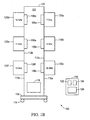
- FIG. 1A illustrates a rack system 100 with a rack 101 according to one embodiment.
- rack system 100 can be operated by a person who is unskilled in the skilled area of technology.
- the rack system 100 can be operated by a manufacturing plant operator unskilled in the area of microwave technology.
- rack systems 100 are installed at a contract manufacturer's facility and operated by less skilled persons with little training for operating and maintaining it.
- the rack system 100 is associated with a rack identifier, a part number, a serial number, or any other combination of one or more numbers, characters, or the like.
- the rack identifier is attached to the rack 100, for example, in the form of a label, bar code, or the like.
- the rack system 100 includes the rack 101 with a frame 102, plates 104a-f, shields 106a-f, an adapter 116, and a detector 118.
- the same 102 is formed as a skeleton structure or any other suitable structure.
- the frame 102 includes a frame bottom 108 and a carrier 114.
- the carrier 114 is attached to the frame bottom 108 or the frame body rests on the carrier 114 with its bottom touching the carrier 114.
- the carrier 114 includes wheels, gliders or legs. In one embodiment, the wheels are castors.
- the rack 101 is made, in whole or in part, from rigid materials such as metal or plastic. Any part that needs to be conductive is made of aluminum, steel or any other suitable material. Any part that needs to be non-conductive is made of plastic, wood or any other suitable material.
- the plates 104a-f are coupled to the frame 102 on each side of the frame 102 facing outwards 110a-b and inwards 112a-b.
- plates 104a-c are coupled to the frame on one side 110a and plates 104d-f are coupled to the other side 110b.
- the shields 106a-f are coupled to the frame on the sides of the frame, both of which are interior sides, i.e., facing inwards 112a-b and opposite to the corresponding plates 104a-f.
- shield 106a is coupled to the frame 102 on the interior side 112a opposite to the corresponding plate 104a.
- a plate 104 is typically configured for an operating mode.
- the operating mode includes any one or a combination of an operating frequency range, a wavelength, a type of fiber design and a core diameter (e.g., of an optical fiber).
- the operating mode correlates to or is obtained via direct or indirect correlation with a serial number, a part number, a product identifier, a customer identifier, or any combination thereof.
- the operating mode may additionally or alternatively be an angle of mounting a unit on a plate 104.
- the plates 104a-f are configured for the same operating mode (although they may be configured differently in other embodiments).
- Such operating mode is, for example, a 7 GHz operating frequency vertical mounting mode.
- Mounting of a unit on a plate 104 preferably imitates field installations and simulate field use and environment.
- an outdoor unit of a split-mount microwave radio system is mounted on a plate 104 as it would in its normal commercial installation.
- One such installation requires an angle of mounting to imitate horizontal or vertical polarization.
- Such angle is predetermined.
- an angle of 180° relative to ground is selected to imitate a vertical field mounting of the unit.
- the angle of 90° relative to ground is selected to imitate a horizontal field mounting of the unit.
- imitating field environment includes imitating air flow or other field use conditions. The air flow conditions imitate air flow around the unit in the field or air flow between various units in a single installation.
- units of various manufactured products include technology in a skilled area.
- Such technology includes microwave radio technology, fiber optic technology, acoustic technology or any combination thereof.
- a unit such as an outdoor unit of a split-mount microwave radio system, has a configuration particular to it.
- the configuration accommodates an operating frequency, wavelength, etc. Indeed, the configuration accommodates various product operating modes.
- the structure of the shields 106a-f is designed to mitigate interference that tends to be generated by or which affects various units when mounted on the rack 101 and processed in close proximity to each other.
- Interference includes electrical interference, electromagnetic interference (EMI), or both.
- EMI electromagnetic interference
- EMI electromagnetic interference
- processing such interference also occurs between various units mounted on different racks located in close proximity to each other. For example, different racks located in the same temperature chamber.
- the adapter 116 functions as a hub of operating signals for processing units.
- the adapter 116 is operative to commmunicate operating signals to and from a unit when mounted on a plate 104.
- such operating signals are communicated to and from a system external to the rack 101 (remote system not shown).
- the external system is a test system and the operating signals include test signals.
- the adapter 116 includes connector(s) for conveying the operating signals.
- the connectors include coaxial cables.
- the kind of unit to be processed affects the type of communication, operating signals, connectors, cables, optical fibers, etc. used in conjunction with the rack system 100.
- the adapter 116 when a unit includes fiber optic technology, the adapter 116 is configured for fiber optic operating signals and the connectors include optical fiber connectors.
- the adapter 116 includes an adapter panel 900 ( Figure 9A ) operatively coupled to the frame 102, the frame bottom 108, or both.
- Each of the connectors have a connector mode.
- Examples of connector modes include an operating frequency range or an operating wavelength.
- a connector identifier, a type of fiber design, a part number, a serial number, a customer number or any combination thereof are correlated directly or indirectly to a connector mode.
- the rack system 100 is provided with a detector 118 in one aspect.
- the detector 118 is fixedly or removably attached to the rack 100.
- the detector 118 is operative to obtain identifying information from the various units and plates. Identifying information helps determine whether there is a match between the configuration of a unit and the operating mode of a plate 104 on which such unit is to be mounted. The identifying information may further help determine whether there is a match between such unit configuration and the connector mode of the connector.
- the detector 118 may be therefore adapted to determine whether there is a match by comparing the identifying information associated with a unit, a plate 104, the connector, or any combination thereof. For example, the detector 118 determines that a match exists if a unit, a plate 104 and a connector are all adapted for the same particular operating mode (e.g., the same operating frequency range).
- the detector 118 includes a data retrieval device 122, a processor 124 and a memory 126.
- the data retrieval device 122 is configured to obtain data associated with the particular rack 101, a plate 104, a unit, a connector, or any combination thereof.
- the data retrieval device 122 includes one or more of a scanner, a bar code reader, a keyboard, a key pad, a pointing device, and a voice recognition device.
- the processor 124 is operative to receive data, such as data obtained using the data retrieval device 122 and, in response to program instructions, to determine whether or not processing of a unit can proceed or should be barred. Such determination is based on a comparison between the obtained data and predetermined matching information.
- the predetermined matching information includes matches between a rack, a unit, a plate and a connector, in any combination, and a match can be in terms of identifier, configuration and operating modes.
- the processor 124 is integral to or coupled to the detector 118.
- the detector 118 also has a memory 126 operative to store the rack identifier, the configuration of various units, the operating mode (of plates), the connector modes, predetermined matches, in any form or variation thereof.
- the memory 126 is configured for storing program instructions to be executed by the processor 124.
- one or more of the data retrieval component 122, the processor 124, and the memory 126 is operative to receive commands from an external system.
- one or more components of the detector 118 are automated, i.e., require input or supervision by an operator.
- one or more components of the detector 118 is automatic, i.e., require no input or supervision by the operator.
- one or more functions of the detector 118 are performed manually. For example, obtaining data associated with a plate 104 may be performed by visual inspection of a bar code, label, or other identifier attached to such plate.
- storing obtained data is performed manually (by the operator), automatically (e.g., via program instructions executed on the processor 124), in an automated fashion (e.g., via keyboard entry or other input device used by the operator), or any combination thereof.
- FIG. 1B illustrates another rack system embodiment (and components it has in common with the foregoing embodiment are typically called out by similar numbers).
- This rack system 150 comprises a rack 103 with a frame, such as frame 102, the frame bottom 108, plates 120a-f, the shields 106a-f, the carrier 114, the adapter 116, and the detector 118.
- the detector 118 includes the data retrieval device 122, the processor 124, and the memory 126.
- the plates 120a-f are configured for various operating modes (as opposed to all being the same).
- the plates 120a-f are configured for various operating frequencies, such as 7 GHz, 8 GHz, 38 GHz, 15 GHz, 11 GHz, and 13 GHz, respectively. Other combinations of operating modes, number of plates 120, etc. are possible.
- Figures 2A-C show different views of a frame according to one embodiment (e.g., frame of rack 101 or 103).
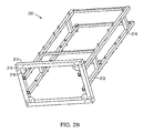
- Figure 2A illustrates a perspective view of the frame 200.
- the frame 200 comprises, respectively, front and rear posts 202a-b, front and rear lateral members 204a-b, and left and right members 206a-b.
- the front lateral members 204a are operative to couple the front posts 202a to each other.
- the rear lateral members 204b are operative to couple the rear posts 202b to each other.
- the left and right members 206a-b are operative to couple the front posts 202a to the rear posts 202b.
- the coupling between posts is typically mechanical to provide rigidity.
- the mechanical connections are implemented in various ways, as commonly known.
- each of the members 204a-b, 206a-b includes an upper and a lower member.
- Other embodiments may include fewer or more members.
- one embodiment includes three front lateral members 204a (e.g., an upper, a lower and a center member).
- a further embodiment includes a single left member 206a and a single right member 206b.
- the frame 200 further comprises plate mounting studs 208a-d (two sets of studs are shown, upper and lower, but there may be room for other sets of studs for mounting additional plates).
- the plate mounting studs 208a-d mate with a plate, as it is mounted on the frame 200.
- the frame 200 is configured for mounting up to six plates 104 (e.g., plates 104a-f), with each plate 104 being mounted to the rack frame 200 via four plate mounting studs 208a-d.
- each plate 104 are mounted using more or fewer plate mounting studs 208.
- the frame 200 allows for mounting more or fewer than six plates 104.
- the plate mounting studs 208 are fastened to the frame 200 with bolts or other known fasteners (not shown).
- the frame 200 further includes a frame bottom 210 and gussets 218.
- the frame bottom 210 is coupled to one end of each of the front and rear posts 202a-b.
- the gussets 218 are formed as plates, and each of the gussets 218 are coupled to one corner of the frame bottom 210.
- the gussets 218 are typically used to add strength to the frame 200, for example, by reinforcing the corners of the frame bottom 210.
- the frame 200 also includes mounting holes.
- the mounting holes include one or more of adapter mounting holes 212 and connector mounting holes 214.
- the adapter mounting holes 212 are operative to couple an adapter plate (item 900 in Figure 9 ) to the frame 200.
- the adapter mounting holes 212 are located in the front and rear posts 202a and 202b, respectively, on the right side of the plate.
- the connector mounting holes 214 are operative to couple (e.g., affix) the connectors (not shown) to the frame 200.
- Figure 2B illustrates a perspective view of the frame 200 from a different angle. This view shows one possibility of coupling the gussets 218 to the frame bottom 210.
- the frame 200 also includes carrier mounting holes 216 operative to couple the carrier 114 to the frame bottom 210.
- the frame 200 includes more or fewer than the mounting holes 212, 214, 216 illustrated in Figures 2A-B .
- Figure 2C illustrates a side view of a rack frame 250.
- the frame 250 is configured to mount plates 104 asymmetrically, i.e., offset from each other, or staggered. That is, plate mounting studs 208 on the front and rear posts 202a and 202b, respectively, are offset.
- One possible advantage of such asymmetric configuration is that the frame 250 is constructed with shorter left and right members 206a-b than it would be in a symmetric configuration (such as that illustrated in Figure 2A ).
- a symmetric configuration accommodates the full depth of two shields facing but not touching each other, whereas the offset in an asymmetric configuration may obviate this requirement.
- FIG. 3 is a block diagram of a plate system 300 according to one embodiment.
- a plate 104 is configured to carry (or hold) two units 302a-b.
- This configuration allows the two units 302a-b to be mounted on the same plate and to communicate with each other during processing.
- This configuration imitates field use conditions of a communication system (not shown) such as a point-to-point wireless communication system.
- the plate system 300 comprises a plate (e.g., plate 104a), a shield 106 (e.g., shield 106a), two units 302a-b and interfaces 304a-b.
- the units communicate with each other via an interface which is preferably enclosed by the shield.
- the shield 106 houses unit adapters 306a-b, attenuators 308a-b, and a shield connector 310 in order to allow the units 302a-b to communicate with each other substantially without interference.
- Each of the two units 302a-b mounted on the plate are operatively coupled to its respective interface 304a-b.
- Each interface 304a-b is in turn operatively coupled to the respective unit adapter 306a-b and attenuator 308a-b via the shield connector 310.
- the units 302a-b include radios 302a-b, such as outdoor units of a split-mount microwave radio system.
- the radios 302a-b are operative to receive and transmit signals.
- one radio e.g., radio 302a
- the other radio e.g., radio 302b
- the shield 106 is operative to mitigate interference with signals transmitted between radios 302a-b.
- the interference is generated, for example, by other units (not shown) mounted on an adjacent plate which are processed substantially simultaneously as the radios 302a-b.
- the adjacent plate is mounted on the same rack as the plate 104 or on another rack located in the same processing chamber.
- the nature of the network depends on the technology incorporated into the units.
- the network is a wireless communication system, a microwave radio network, a fiber optic network, an acoustic network or the like.
- the interfaces 304a-b are configured for a particular operating mode. Thus, interfaces 304a-b configured for a plate 104a that has one operating mode are different from interfaces configured for another plate 104b that has a different operating mode.
- the interfaces 304a-b are configured such that a unit having a configuration incompatible with the operating mode of the plate cannot be mechanically and/or electrically coupled to such interface 304a-b.
- an interface 304a-b is a waveguide interface (as described in further detail with reference to Figure 5 ).
- the unit adapters 306a-b are typically used for matching signals to the characteristics of the units such that an operative connection can be made within the shield 106 between the two units 302a-b.
- the unit adapters 306a-b are operative to convert a signal in one form associated with a first medium to a signal in another form associated with a second medium
- the first medium is wireless medium (e.g., air), a fiber optic medium, an acoustic medium, or the like.
- the signal whose signal than is converted is an electromagnetic, optical or acoustic signal.
- the second medium is a wire (e.g., a coaxial cable or an optical fiber).
- the shield connector 310 includes the second medium.
- the unit adapters 306a-b are waveguides or transducers 306a-b. In other embodiments, the unit adapters 306a-b are piezoelectric acoustic wave filters or fiber optic converters.
- the unit adapters 306a-b can be coupled to the rack, it tends to save the step of an operator attaching a unit adapter to a unit prior to processing it and the further step of detaching the unit adapter following completion of such processing. This avoids human errors and saves time, and also avoid possible damage to the unit, the unit adapter 306, or both.
- the attenuators 308a-b are typically operative to reduce the amplitude or power of a signal transmitted between the two units without substantially distorting such signal.
- the attenuators 308a-b are passive or active devices. Passive devices can include resistors. Examples of attenuators 308a-b are power attenuators and electrical attenuators.
- the attenuators 308a-b are adapted to provide an amount of attenuation that is fixed, contiguously adjustable, or incrementally adjustable.
- a single unit is mounted on the plate.
- An example is a medical device designed to operate alone. Such medical device can nonetheless cause or be susceptible to interference during processing (e.g., from medical devices mounted on adjacent plates) and will be installed with a shield.
- more than two units of manufactured products e.g., 302a-e
- a power supply network e.g., a supply grid for a geographic area.
- Figures 4A and 4B illustrate, respectively, front and back sides of a plate adapted to accommodate two units (e.g., the radios 302a-b) according to one embodiment.
- the plate 104 comprises interface openings 402a-b, stud insert openings 404, plate mounting holes 412, 414 and ramp mounting holes 410 (e.g., ramp mounting holes 706 of Figure 7 ).
- Each of the interface openings 402a-b is configured for receiving interfaces 304, 306.
- the stud insert opening 404 has an insert end 406 and a stop end 408.
- the insert end 406 is configured with a dimension to match a ramp (e.g., ramp 700 with a diameter of its inner ramp surface 702, as shown in Figure 7 ).
- the stop end 408 is configured with a dimension to match a stop (e.g., a stop 800 with a diameter of its inner stop surface 802, as shown in Figure 8 ).
- the ramp 700 and stop 800 are parts of the unit attachment mechanism and will be described in further detail with reference to Figures 7 and 8 .
- a unit with mounting studs requires, for each stud, a stud insert opening configuration (e.g., 404) for allowing insertion of a mounting stud at the insert end 406 and for turning the unit until the mounting stud reaches the stop end 408 and comes to rest on the stop 800.
- a stud insert opening configuration e.g., 404
- the size and number of the stud insert openings 404 may vary defending on the kind of unit to be mounted on the plate, including its number and size of mounting studs.
- the plate mounting holes 412 are placed anywhere suitable for attachment a plate to the frame; e.g., perimeter, corners, center, or any other place.
- the plate mounting holes 412 are adapted for any suitable type of fasteners for attaching a plate to the rack frame.
- Some embodiments additionally or alternatively include plate mounting holes 414 disposed at or around the center of the plate 104.
- the plate mounting holes 412, 414 are adapted for fasteners such as rivets, screws, bolts or the like. Other types of plate mounting holes 412, 414 may also be used.
- the plate also includes various cutouts, openings, holes and the like for purposes such as but not limited to affixing the plate to the frame, heat dissipation, etc.
- the interfaces (304 a-b, Figure 3 ) for operatively connecting the units are waveguide interfaces.
- a waveguide interface 500 is adapted for an operating frequency range, e.g., 6-11 GHz or 13-38 GHz, where the operating frequency determines the configuration of such waveguide interface.
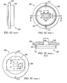
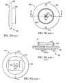
- Figures 5A-5H illustrate various interfaces, with part 1 showing a side view, part 2 showing a front view, part 3 showing a rear view, and so on, and with the different configurations suited for handling different frequency ranges.
- the waveguide interface 500 is shown having a rim 502, a center portion 506, and a rear portion 504.
- the center portion 502 is configured for coupling it to or resting it to on the plate 104.
- the rear portion 504 is configured for mating it with a unit.
- the rim 502 also provides points of mechanical attachment to the unit.
- the waveguide interface 500 further includes waveguide interface plate mounting holes 512 and unit mounting holes 514.
- the waveguide interface 500 is configured such that a mismatched unit cannot be coupled to it.
- the size of the rim 502 may have dimensions (e.g., a diameter) permitting only a matching unit to be mechanically coupled to the waveguide interface 500.
- the waveguide interface 500 typically includes a duct 508. The size and shape of the ducts 508 allows a matching unit to be coupled to the waveguide interface 500.
- the duct 508 has dimensions d1 and d2, as shown.
- dimensions d1 and d2 include 34.85mm and 15.8mm, 28.5mm and 12.62 mm, 22.86mm and 10.16mm, 15.8mm and 7.9mm, 10.6 and 4.32 mm, 7.11mm and 3.56mm, and 19.05mm and 9.53mm, respectively.
- Implementations of the waveguide interfaces 500, 550 may differ in other dimensions as well. For instance, the thickness of the rim 502, rear portion 506 or center portions 504 may vary.
- the cross-section view of the waveguide interface 500 illustrates the front portion 502 formed with an angle ⁇ .
- the angle ⁇ tends to align the unit centrally into the waveguide interface 500.
- the angle ⁇ is 27 degrees.
- FIGS 6A and 6B illustrate, respectively, top and side views of a shield, e.g., 160, according to one embodiment.
- the shield 160 comprises a housing 602 and flanges 604a-d.
- the shield further includes corner fasteners 606 and shield mounting holes 608.
- the flanges 604 are projections of or are coupled to the housing 602 and configured to allow coupling of the housing 602 to the plate 104.
- the corner fasteners 606 include rivets. In other, differently shaped embodiments, the corner fasteners 606 may be omitted.
- the shape and materials of a shield 160, as well as its coupling configuration depend on the shape of a unit, the type of technology incorporated into such unit, and the like.
- Figure 7 illustrates a ramp portion (ramp 700) of an attachment mechanism according to one embodiment.
- the ramp 700 comprises a contoured ramp surface 702, a ramp mounting surface 704, and one or more ramp mounting holes 706 (e.g., ramp mounting holes 410 of Figure 4A ).
- the contour of the ramp surface 702 is configured for receiving a mounting stud attached to a unit.
- the ramp 700 is configured so that, after insertion, a mounting stud scales the ramp surface 702.
- the ramp mounting surface 704 is used for coupling the ramp 700 to a back (or bottom) surface of the plate 104 with the ramp mounting holes 706 configured to receive fasteners for coupling the ramp to the plate.
- the ramp 700 further includes a graded surface 708 configured to facilitate removal of the mounting studs upon completion of unit processing when the unit is demounted.
- the graded surface 708 may be designed to make it easier for the operator to reach (e.g., get a firm grip around) the mounting studs.
- a stop 800 comprises a contoured or graded inner stop surface 802, a stop mounting surface 804, and one or more stop mounting holes 806-
- the stop mounting surface 804 is configured for coupling it to the black surface of the plate 104.
- the contoured inner stop surface 802 is configured for causing a mounting stud to come to a stop upon being turned in the inner ramp surface 702.
- the stop 800 is further configured, alone or in conjunction with the ramp 700, to lock a unit in place when mounted on the plate 104. Locking includes causing a unit to come to a stop (with its mounting studs resting in their respective ramp 700) and stay secure in place during processing (without the aid of an additional fastener or lock mechanism).
- FIG. 9A illustrates an adapter panel of an adapter (e.g., the adapter 116) according to one embodiment.
- the adapter panel 900 comprises one or more connector openings 902 and one or more adapter panel mounting holes 904.
- the adapter panel 900 includes one connector opening 902 for each unit of manufactured product mounted on the rack.
- a rack system comprising six plates, each configured to process two units of manufactured product, includes an adapter panel 900 with at least twelve connector openings 902.
- the number, size and locations of the adapter panel mounting boles 904 are commensurate with the number, size and locations of the adapter mounting holes 212. Additional connector locations may be provided for external system connections.
- Figure 9B illustrates a shape of a connector opening 902 according to one embodiment.
- Other sizes and shapes of the connector opening 902 are possible depending, for example, on the type of technology incorporated into a unit.
- the connector opening 902 is configured for receiving a coaxial cable.
- the connector opening 902 is configured for receiving an optical fiber.
- FIG 10 is a flow diagram of a method using a rack system as described above for processing a manufactured product according to one embodiment.
- the method 1000 begins at step 1002 with an operator removably mounting a unit of manufactured product on a plate.
- step 1002 includes inserting one or more mounting studs of a unit into an insert end (ramp opening). The unit with one or more mounting studs is then turned until the studs reach a respective stop end. Upon completion of step 1002, the unit is locked into place on the plate.
- removably mounting includes removably mounting multiple units of manufactured product, i.e. a pair of radios mounted on a plate. In some embodiments, removably mounting includes removably mounting one or more units of manufactured product on multiple plates (e.g., the plates 104a-f).
- the operating mode is obtained from the plate 104.
- the connector mode associated with the connectors coupled to the adapter 116 is obtained.
- the configuration is obtained from a unit of manufactured products.
- steps 1004, 1006 and 1008 are performed manually (e.g., by visual inspection of a label attached to the plate, the connector or a unit), automatically (e.g., by using a detector), in an automated fashion (e.g., by keyboard entry), or any combination thereof.
- One or more of the operating mode, the connector mode and the configuration are obtained indirectly. This involves deriving the configuration from a product number or serial number of the unit by looking it up in a table or other configuration listing (e.g., in memory).
- steps 1004, 1006 and 1008 are performed prior to step 1002.
- the configuration for example, can be obtained from a unit before the unit is mounted on the plate.
- step 1008 is performed prior to step 1002.
- Step 1010 a determination is made whether a match exists.
- Step 1010 includes comparing one or more of the operating mode of the plate 104, the connector mode, and the configuration of a unit with predetermined matching information (e.g., matching table entries). In one embodiment, the determination is performed by the processor 124 in response to program instructions.
- step 1010 If at step 1010, a match is determined to exist, the method 1000 continues with step 1012 at which a unit is processed. If, at step 1010, a mismatch is found, the method 1000 continues with step 1014, at which processing of the unit is prevented.
- the method 1000 also includes a step 1016 at which a processing result is recorded.
- Step 1016 follows successful or unsuccessful processing of a unit (at step 1012) including when processing is prevented.
- Recording the processing result includes storing data to a memory associated with the rack system (e.g., memory 126 or external memory which is not shown). Recording further includes printing data to a printing device, manually recording data or recording it in an automated fashion (e.g., entering the data to a computerized device via a keyboard).
- the method 1000 ends.
- the method 1000 further includes a step 1018 at which the operator is notified of a mismatch.
- Notifying the operator includes displaying a code, color, or text message, for example, on a display (e.g., on a display included in the detector 118 or in a system external to the rack).
- the method 1000 attempts another pass at processing the unit. The operator may, for example, be prompted (e.g., on the display) to indicate whether or not to try another pass. If the choice, at step 1020, is to try another pass, the method 1000 returns to step 1002. If not, the method 1000 will end.
- the method 1000 upon choosing not to try another pass, the method 1000 includes a step 1022 at which a non-matching unit is replaced. In such an embodiment, the method thereafter returns to step 1002.
- steps 1014 and 1018 may be performed in a different order.
- the operator, at step 1018 is notified that a mismatch exists. Thereafter, the operator, at step 1014, prevents processing of the unit by omitting to push a start button.
- Step 1004 for example, is optional if the operating mode was obtained prevously (e.g., during a prior pass) and stored to memory 126.
- steps 1006 and/or 1008 are optional, if the connector mode and/or the configuration were obtained previously.
- step 1012a involves moving the rack system to the processing chamber.
- step 1012b the rack identifier is obtained.
- the rack identifier may be scanned.
- step 1012b is performed prior to step 1012a, for example, as part of set-up and pre-processing verification.
- Step 1012b is performed more than once, for example, once prior to step 1012a and once following step 1012a.
- different operators can each perform step 1012b.
- the scanning prior to step 1012a is performed by a technician tasked with preparing rack systems for the chamber, and the scanning following step 1012a is performed by a technician tasked with performing the actual processing of various units mounted on the rack system in the chamber.
- step 1012c other data associated with processing is obtained.
- data is obtained via scanning or retrieval from memory and it may contain a box identifier (e.g., a box number of a unit shipping/storage box).
- box identifier e.g., a box number of a unit shipping/storage box.
- Such data may further contain configurations and operating modes correlated with data obtained at steps 1004 - 1008.
- processing of units of manufactured product commences. Such processing includes all or part of the processing to be performed.
- a first part of the processing is performed.
- step 1012 returns to step 1012d for performing additional processing (e.g., second or third iterations, etc.).
- steps 1012d-f are repeated until either the determination is made, at step 1012e, that the processing results fail the unit or the determination is made, at step 1012f, to stop processing.
- Whether to perform all processing in one or multiple iterations depends on the type of processing, the type of technology incorporated in a unit or the like. For example, in embodiments in which processing includes both temperature testing and calibration, the processing is performed in two or more iterations.
- the method may include additional steps (not shown), for example, the step of identifying and labeling a unit as a failed unit. This is done by manually attaching a label to the failing unit, making a data entry into a computerized device, automatically recording the identity of a failed unit, or any combination thereof.
- the present invention contemplates various design approaches for processing units of manufactured products.
- these approaches include removably mounting units on a rack system adapted for use by a relatively unskilled operator and mitigating interference between units of manufactured product during processing thereof
- the present invention has been described in considerable detail with reference to certain preferred embodiments thereof other embodiments are possible.
Landscapes
- Physics & Mathematics (AREA)
- General Physics & Mathematics (AREA)
- Shielding Devices Or Components To Electric Or Magnetic Fields (AREA)
- Cooling Or The Like Of Electrical Apparatus (AREA)
Description
-
- This invention is generally reflated to test devices and, more specifically, to test racks for manufactured products, such as microwave radios.
- Manufacturing of products often includes processing, such as testing of product configurations. To detect potential problems prior to shipping, such processing ideally replicates the use a purchaser will make of the product and the environment in which such product is used (e.g., field conditions, laboratory conditions, etc.). Some products include technology in particularly skilled areas. Examples of skilled areas of technology include radio frequency and microwave technologies in products such as microwave radios, medical devices such as X-ray, computed axial tomography (CAT) or magnetic resonance imaging (MRI) machines, or fiber optics systems. Replicating the purchaser's use, conditions of use, or both, includes mounting the product in a particular way (e.g., in a vertical mode), in a special location (e.g., outdoors) or both. However, it is difficult to process products mounted in such a way (for instance, products often end up being processed while mounted horizontally and face down on a test bench indoors).
- Often, multiple units of manufactured product need to be processed at the same time. Such processing causes interference between units resulting in, for example, false failures. Examples of interference include power leakages and electromagnetic interference (EMI). These false failures correspond to false errors and/or error measurements in data traffic.
- Manufactured products often include one or more subassemblies capable of configuration, such as operating frequency range, receive mode, transmit mode, network topology configuration settings, etc. Subassemblies include components incorporated into a manufactured product. Processing of manufactured product ideally includes all possible combinations of product configurations and product use conditions. Many tasks involved in such processing require an operator skilled in the product technology and manufacturing processes ,with knowledge of the customer's use and conditions of use of the manufactured product.
- Misidentifying and erroneously processing or other mishandling of a manufactured product results in unacceptable performance, failure to conform to regulations or standards, or other anticipated or unanticipated problems. In some skilled areas of technology, such as those involved in medical devices i.e. the product is a medical device, product detects sometimes cause physical harm. Therefore, there is a need to improve manufacturing methods and systems.
-
US 6,088,582 teaches a controlled environment radio test apparatus with chambers for first and second radio devices.JP 4203980 - In one aspect, the present invention relates to a system, comprising:
- a rack having a frame;
- a plate coupled to the frame andconfigured for a particular operating mode comprising an operating frequency range, the plate including an attachment mechanism adapted for removably mounting on the plate a manufactured product having a configuration, the plate being configured to prevent operation of the manufactured product if the particular operating mode of the plate mismatches an operating mode of the configuration;
- an adapter coupled to the frame and configured for communicating electronicoperating signals to and from the manufactured product, when mounted on the plate; and
- a detector configured, using a processor, to determine whether the configuration of a manufactured product is in accordance with the particular operating mode of the plate.
- Various considerations in the design of manufacturing systems and methods are based, in part, on the foregoing observations. These considerations include the possible benefits of processing manufactured product in an environment similar to that in which the manufactured product will be used. One desired aspect of such design is to substantially decrease the need for a skilled operator. Another desired aspect of such design is to decrease the likelihood of unreliable results by, for example, reducing interference between units of manufactured product being processed.
- In particular, the design contemplates rack systems and methods using them for processing of manufactured product that incorporates skilled areas of technology. One preferred approach includes mounting one but typically more than one of the manufactured products or units of manufactured product on a rack system. The rack system includes a carrier (e.g., base and wheels) to facilitate movement, such as to and from a test chamber. In one aspect, the rack system is be modular, for example, includeing a frame with multiple plates.
- The plate design in one aspect includes a structure for mounting a manufactured product on the plate substantially without fasteners. The mounting structure in one aspect includes one or more attachment mechanisms each having a ramp and a stop coupled to the back side of the plate. Accordingly, the manufactured product is configured with one or more mounting studs. A mounting stud coupled to a manufactured product is designed to fit into an insert end of the ramp and (by turning the manufactured product) it can be turned to scale the ramp until it reaches the stop.
- In one aspect, each plate is configured for a different operating mode. The plates are configured such that only a matching manufactured product is processed when mounted on a plate (and mismatched products are properly rejected). A match exists if a manufactured product, the plate on which it is mounted, and a connector communicatively coupling a manufactured product to a source of operating signals are configured for the same particular operating mode, such as an operating frequency range. To this end, an aspect of the rack system includes a detector for obtaining data necessary for determining whether a match exists between the manufacture product and the plate. Such data is thus associated with the manufactured product, the plate, the connector, or any combination thereof. Matching configurations can be done using a processor, software, program instructions, memory, and the like. Preferably, this approach includes notifying an operator if processing fails, such as if a mismatch is detected.
- In one aspect, the plate includes a shield for mitigating interference between units of manufactured product. During processing, the units generate interference or the units are affected by such interference, or both. By mitigating interference between units that are being processed, the design reduces the likelihood of incorrectly rejecting units of manufactured product as failed units. This in turn reduces the time required to look for the root cause of a false failure problem (such as false test result, bad data, etc.).
- For processing manufactured products, the rack system further include an adapter to which a manufactured product is operatively coupled via the connector. The adapter allows for operating signals to be communicated to and from mounted units of manufactured product during processing thereof. A manufacturing system design using this approach is useful for processing outdoor units of split-mount systems such as microwave radio systems.
- This manufacturing system design provides advantages in addition to mitigating interferences and preventing mismatched units processing. Among such advantages is the ability to mount and dismount manufactured products on and off the plate substantially without needing additional fasteners. Another possible advantage is the ability to mount manufactured product at an angle or in a manner that otherwise simulates field mounting. For example, an outdoor unit of a split-mount microwave radio system is mounted in a vertical mode to simulate air flow surrounding the unit and further to simulate the connection to the unit when field mounted.
- Furthermore, the manufacturing system is designed to increase the repeatability and reliability of processing results and reduce the possibilities for human errors. The system configuration reduces set-up time by substantially eliminating steps of manually coupling units to test equipment, by reducing the time to mount and dismount manufactured product and to carry such manufactured product to and from a processing chamber. The system configuration, allows less skilled operators to operate the manufacturing system for processing manufactured products that include technology in high skill areas. Therefore, such manufacturing systems can be easily installed at a contract manufacturer's facility and require low maintenance and training of new operators. Another possible advantage is that the adapter can facilitate communicating signals to and from and thereby operatively accessing and manipulating manufactured products once mounted on the rack system (without needing physical access to them).
- Accordingly, the following embodiments are examples of a rack system and a method for processing manufactured products. In accordance with one embodiment, a rack system for processing units of manufactured products, includes a rack having a frame. The rack system typically also includes a plate configured for a particular operating mode coupled to the frame of the rack. The frame is typically configured to support a plurality of plates. Each plate includes an attachment mechanism adapted for removably mounting on the plate a manufactured product having a configuration. The rack system in one aspect includes an adapter coupled to the frame and configured for communicating operating signals to and from a manufactured product, when mounted on the plate, and a detector associated with the rack and configured for determining whether there is a match between the configuration of a manufactured product and the particular operating mode of the plate.
- A rack system preferably also includes a shield attached to the plate and configured to mitigate interference generated by or affecting a manufactured product (i.e., interference with or from the manufactured product). In such rack, the detector includes a data retrieval device configured to obtain data from a manufactured product, the plate, and the rack. The obtained data includes an operating frequency range, a plate identifier, a rack identifier, a product identifier, a customer identifier, a serial number, a part number, or any combination thereof. The detector in one aspect further includes a processor operatively coupled to the data retrieval, device and configured to determine whether or not to commence processing of a manufactured product based on the data obtained from the data retrieval device. This includes determining whether or not there is a match on the basis of which the determination or whether or not to commence the processing is made. Hence, the rack system is advantageously configured so that it can be operated and maintained by an operator having substantially no skill in an area of technology which a manufactured product incorporates.
- A rack system in one aspect further comprises a plate system associated with each plate. This is useful when the plate is configured for mounting thereon a plurality of manufactured products and the plate system is configured for communications between the plurality of manufactured products when so nnounted. The plate system includes, for each manufactured product, an interface to such manufactured product, a unit adapter operatively coupled to the interface, and an attenuator operatively coupled to the unit adapter. A pair of the attenuators in the plate system are connected to each other via a cable in order to facilitate communications between manufactured products associated with them, when mounted on the plate.
- According to one embodiment of a method for processing manufactured products, the method steps include providing a rack with a frame, the rack further including a plate configured for an operating mode and mounted on the frame, as well as a detector and an adapter. The method further includes removably mounting on the plate a manufactured product having a configuration, obtaining the operating mode from the plate and a configuration from the manufactured product via the detector, comparing and determining whether there is a match between the operating mode and the configuration, and, in response to determining that there is a match, allowing processing of that manufactured product to commence by communicating operating signals to and from such manufactured product via the adapter. However, in response to determining that there is no match, the method provides an indication and/or prevents processing of the manufactured product.
- One application for rack systems and a method using them is in the manufacture of a wireless radio system, particularly one that operates in the microwave frequency range. Hence, such rack systems and methods are adapted for processing outdoor units of split-mount wireless radio systems.
- These and other features, aspects and advantages of the present invention will become better understood from the description herein, appended claims, and accompanying drawings as hereafter described.
- The accompanying drawings, which are incorporated in and constitute a part of this specification, illustrate various aspects of systems and methods for processing manufactured products and together with the description serve to explain various principles thereof. Wherever convenient, the same reference numbers will be used throughout the drawings to refer to the same or like elements.
-
figure 1A and1B each illustrates a rack according to one embodiment. -
Figures 2A-C show different views of a frame of a rack according to one embodiment. -
Figure 3 illustrates a block diagram of a plate system according to one embodiment. -
Figures 4A and 4B illustrates, respectively, front and back views of a plate according to one embodiment. -
Figures 5A-5H are each an illustration of a waveguide interface with diagrams (parts 1-4) of its side, front, rear and cross-section views. -
Figures 6A and 6B illustrate, respectively, top and side views of a shield according to one embodiment. -
Figure 7 illustrates a ramp portion of an attachment mechanism on a plate according to one embodiment. -
Figure 8 illustrates a stop portion of an attachment mechanism on a plate according to one embodiment. -
Figures 9A and 9B illustrate an adapter panel of an adapter according to one embodiment. -
Figure 10 is a flow diagram of a method for processing a manufactured product according to one embodiment. -
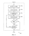
Figure 11 is a flowchart illustrating the step of processing a manufactured product, according to one embodiments. - This description is provided in the context of the present Application for Letters Patent and its requirements to enable a person of ordinary skill in the art to make and use the invention. Various modifications to the embodiments described and shown are possible and the generic principles defined herein may be applied to these and other embodiments without departing from the invention. Thus, the present invention is to be accorded the widest scope consistent with the principles, features and teachings disclosed herein.
- As mentioned, various embodiments of manufacturing systems and methods using them are designed for processing manufactured products. For convenience, but without introducing any limitation thereby, a single manufactured product of any kind can be referred to as a "unit" and multiple manufactured products of one or more kinds can be referred to, respectively, as "units of a naanufactured product," "various units," "units of any kind," or simply "units."
- In one aspect, a manufacturing system for processing one or more manufactured products according to the invention is implemented as a rack system. A rack system typically comprises a rack with a frame and a carrier such as a base with legs, skids or wheels. The frame ise formed as a skeleton structure or any other suitable structure. One or more plates are coupled to the frame with each plate adapted for mounting thereon a manufactured product. The rack system includes multiple plates, where each plate is configured for a different operating mode. Different plates with different operating modes can accommodate different types, configurations or version of manufactured products. To this end, the rack system also includes an adapter for communicating various operating signals to and from manufactured products when mounted on the plate.
- The preferred approach to designing a manufacturing system for processing manufactured products includes managing (e.g., permitting or preventing) the processing of a unit. Therefore, the rack system further includes a detector for obtaining data associated with individual units of any kind, individual plates, or both, and for determining whether a match exists between the configuration of an individual unit and the operating mode of the plate on which it is to be mounted- Any time a mismatch between a unit and a plate is detected, the rack system prevents processing of such mismatched unit, notifys the operator of such mismatch, or both. The operator is then be guided to take corrective action, typically by being instructed to replace the mismatched unit with a matching unit so as to allow for the processing to commence. For this, the operator need not be skilled.
- The design approach for the foregoing takes into consideration the beneficial aspects as well as possible tradeoffs attributed to various manufacturing system designs. One design includes manually obtaining, e.g., by visual inspection, the configuration of a manufactured product, the operating mode of the plate or both. The configuration obtained is recorded manually on paper or the like. Alternatively or additionally, the configuration is recorded electronically, for example, in a computerized device including a memory (e.g., in the detector).
- Alternatively, such design includes automated or automatic retrieval of data and/or manual, automated, or automatic determination that a match exists. A human error in the determination may not necessarily lead to a unit's subsequently failing processing. However, even if it passes processing, a unit of manufactured product may nonetheless fail in the field.
- Thus, a preferred approach generally includes electronic means for obtaining data and verifying a match between the plate and a unit mounted thereon. The preferred approach further includes a rack, such as the one described above, which requires a relatively low-skilled operator even when a manufactured product incorporates technology in a high-skilled area.
- To illustrate, rack systems and methods for processing manufactured products are explained below in conjunction with the drawings.
Figure 1A illustrates arack system 100 with arack 101 according to one embodiment.Such rack system 100 can be operated by a person who is unskilled in the skilled area of technology. For example, therack system 100 can be operated by a manufacturing plant operator unskilled in the area of microwave technology. Hence,such rack systems 100 are installed at a contract manufacturer's facility and operated by less skilled persons with little training for operating and maintaining it. Therack system 100 is associated with a rack identifier, a part number, a serial number, or any other combination of one or more numbers, characters, or the like. The rack identifier is attached to therack 100, for example, in the form of a label, bar code, or the like. - In one aspect, the
rack system 100 includes therack 101 with aframe 102,plates 104a-f, shields 106a-f, anadapter 116, and adetector 118. The same 102 is formed as a skeleton structure or any other suitable structure. Theframe 102 includes aframe bottom 108 and acarrier 114. Thecarrier 114 is attached to theframe bottom 108 or the frame body rests on thecarrier 114 with its bottom touching thecarrier 114. Thecarrier 114 includes wheels, gliders or legs. In one embodiment, the wheels are castors. Therack 101 is made, in whole or in part, from rigid materials such as metal or plastic. Any part that needs to be conductive is made of aluminum, steel or any other suitable material. Any part that needs to be non-conductive is made of plastic, wood or any other suitable material. - The
plates 104a-f are coupled to theframe 102 on each side of theframe 102 facing outwards 110a-b and inwards 112a-b. In the illustrated embodiment,plates 104a-c are coupled to the frame on oneside 110a andplates 104d-f are coupled to theother side 110b. Theshields 106a-f are coupled to the frame on the sides of the frame, both of which are interior sides, i.e., facing inwards 112a-b and opposite to the correspondingplates 104a-f. For example,shield 106a is coupled to theframe 102 on theinterior side 112a opposite to thecorresponding plate 104a. - A
plate 104 is typically configured for an operating mode. The operating mode includes any one or a combination of an operating frequency range, a wavelength, a type of fiber design and a core diameter (e.g., of an optical fiber). The operating mode correlates to or is obtained via direct or indirect correlation with a serial number, a part number, a product identifier, a customer identifier, or any combination thereof. The operating mode may additionally or alternatively be an angle of mounting a unit on aplate 104. In this rack system embodiment, theplates 104a-f are configured for the same operating mode (although they may be configured differently in other embodiments). Such operating mode is, for example, a 7 GHz operating frequency vertical mounting mode. - Mounting of a unit on a
plate 104 preferably imitates field installations and simulate field use and environment. For example, an outdoor unit of a split-mount microwave radio system is mounted on aplate 104 as it would in its normal commercial installation. One such installation requires an angle of mounting to imitate horizontal or vertical polarization. Such angle is predetermined. For example, an angle of 180° relative to ground is selected to imitate a vertical field mounting of the unit. In another embodiment, the angle of 90° relative to ground is selected to imitate a horizontal field mounting of the unit. In some embodiments, imitating field environment includes imitating air flow or other field use conditions. The air flow conditions imitate air flow around the unit in the field or air flow between various units in a single installation. - Typically, units of various manufactured products include technology in a skilled area. Such technology includes microwave radio technology, fiber optic technology, acoustic technology or any combination thereof. Thus, a unit, such as an outdoor unit of a split-mount microwave radio system, has a configuration particular to it. The configuration accommodates an operating frequency, wavelength, etc. Indeed, the configuration accommodates various product operating modes.
- As will be later described in more detail, the structure of the
shields 106a-f is designed to mitigate interference that tends to be generated by or which affects various units when mounted on therack 101 and processed in close proximity to each other. Interference includes electrical interference, electromagnetic interference (EMI), or both. During processing, such interference also occurs between various units mounted on different racks located in close proximity to each other. For example, different racks located in the same temperature chamber. - In this rack system configuration, the
adapter 116 functions as a hub of operating signals for processing units. Thus, theadapter 116 is operative to commmunicate operating signals to and from a unit when mounted on aplate 104. In some embodiments, such operating signals are communicated to and from a system external to the rack 101 (remote system not shown). For example, the external system is a test system and the operating signals include test signals. Theadapter 116 includes connector(s) for conveying the operating signals. The connectors include coaxial cables. The kind of unit to be processed affects the type of communication, operating signals, connectors, cables, optical fibers, etc. used in conjunction with therack system 100. For example, when a unit includes fiber optic technology, theadapter 116 is configured for fiber optic operating signals and the connectors include optical fiber connectors. In some rack system embodiments, theadapter 116 includes an adapter panel 900 (Figure 9A ) operatively coupled to theframe 102, theframe bottom 108, or both. - Each of the connectors have a connector mode. Examples of connector modes include an operating frequency range or an operating wavelength. Furthermore, a connector identifier, a type of fiber design, a part number, a serial number, a customer number or any combination thereof are correlated directly or indirectly to a connector mode.
- As mentioned, the
rack system 100 is provided with adetector 118 in one aspect. Thedetector 118 is fixedly or removably attached to therack 100. Thedetector 118 is operative to obtain identifying information from the various units and plates. Identifying information helps determine whether there is a match between the configuration of a unit and the operating mode of aplate 104 on which such unit is to be mounted. The identifying information may further help determine whether there is a match between such unit configuration and the connector mode of the connector. Thedetector 118 may be therefore adapted to determine whether there is a match by comparing the identifying information associated with a unit, aplate 104, the connector, or any combination thereof. For example, thedetector 118 determines that a match exists if a unit, aplate 104 and a connector are all adapted for the same particular operating mode (e.g., the same operating frequency range). - To this end, the
detector 118 includes adata retrieval device 122, aprocessor 124 and amemory 126. Thedata retrieval device 122 is configured to obtain data associated with theparticular rack 101, aplate 104, a unit, a connector, or any combination thereof. Thedata retrieval device 122 includes one or more of a scanner, a bar code reader, a keyboard, a key pad, a pointing device, and a voice recognition device. - The
processor 124 is operative to receive data, such as data obtained using thedata retrieval device 122 and, in response to program instructions, to determine whether or not processing of a unit can proceed or should be barred. Such determination is based on a comparison between the obtained data and predetermined matching information. The predetermined matching information includes matches between a rack, a unit, a plate and a connector, in any combination, and a match can be in terms of identifier, configuration and operating modes. Theprocessor 124 is integral to or coupled to thedetector 118. - The
detector 118 also has amemory 126 operative to store the rack identifier, the configuration of various units, the operating mode (of plates), the connector modes, predetermined matches, in any form or variation thereof. Thememory 126 is configured for storing program instructions to be executed by theprocessor 124. In some embodiments, one or more of thedata retrieval component 122, theprocessor 124, and thememory 126 is operative to receive commands from an external system. - Also, in some embodiments, one or more components of the detector 118 (e.g., the data retrieval device 122) are automated, i.e., require input or supervision by an operator. Alternatively, one or more components of the
detector 118 is automatic, i.e., require no input or supervision by the operator. As a further alternative, one or more functions of thedetector 118 are performed manually. For example, obtaining data associated with aplate 104 may be performed by visual inspection of a bar code, label, or other identifier attached to such plate. Furthermore, storing obtained data is performed manually (by the operator), automatically (e.g., via program instructions executed on the processor 124), in an automated fashion (e.g., via keyboard entry or other input device used by the operator), or any combination thereof. - Having described one,
Figure 1B illustrates another rack system embodiment (and components it has in common with the foregoing embodiment are typically called out by similar numbers). Thisrack system 150 comprises arack 103 with a frame, such asframe 102, theframe bottom 108,plates 120a-f, theshields 106a-f, thecarrier 114, theadapter 116, and thedetector 118. Thedetector 118 includes thedata retrieval device 122, theprocessor 124, and thememory 126. In this embodiment, theplates 120a-f are configured for various operating modes (as opposed to all being the same). For example, theplates 120a-f are configured for various operating frequencies, such as 7 GHz, 8 GHz, 38 GHz, 15 GHz, 11 GHz, and 13 GHz, respectively. Other combinations of operating modes, number of plates 120, etc. are possible. - As to the frame, a number of possible configurations are possible, one example being a skeleton frame structure. In some embodiments, the frame is made in part or entirely of rigid and conductive materials.
Figures 2A-C show different views of a frame according to one embodiment (e.g., frame ofrack 101 or 103).Figure 2A illustrates a perspective view of theframe 200. Theframe 200 comprises, respectively, front andrear posts 202a-b, front and rearlateral members 204a-b, and left andright members 206a-b. The frontlateral members 204a are operative to couple thefront posts 202a to each other. Likewise, the rearlateral members 204b are operative to couple therear posts 202b to each other. The left andright members 206a-b are operative to couple thefront posts 202a to therear posts 202b. The coupling between posts is typically mechanical to provide rigidity. The mechanical connections are implemented in various ways, as commonly known. - In the illustrated embodiment, each of the
members 204a-b, 206a-b includes an upper and a lower member. Other embodiments may include fewer or more members. For example, one embodiment includes three frontlateral members 204a (e.g., an upper, a lower and a center member). A further embodiment includes a singleleft member 206a and a singleright member 206b. - The
frame 200 further comprisesplate mounting studs 208a-d (two sets of studs are shown, upper and lower, but there may be room for other sets of studs for mounting additional plates). In each set, theplate mounting studs 208a-d mate with a plate, as it is mounted on theframe 200. In the illustrated embodiment, theframe 200 is configured for mounting up to six plates 104 (e.g.,plates 104a-f), with eachplate 104 being mounted to therack frame 200 via fourplate mounting studs 208a-d. In other embodiments, eachplate 104 are mounted using more or fewer plate mounting studs 208. In yet other embodiments, theframe 200 allows for mounting more or fewer than sixplates 104. The plate mounting studs 208 are fastened to theframe 200 with bolts or other known fasteners (not shown). - In one aspect, the
frame 200 further includes aframe bottom 210 andgussets 218. Theframe bottom 210 is coupled to one end of each of the front andrear posts 202a-b. Thegussets 218 are formed as plates, and each of thegussets 218 are coupled to one corner of theframe bottom 210. Thegussets 218 are typically used to add strength to theframe 200, for example, by reinforcing the corners of theframe bottom 210. - The
frame 200 also includes mounting holes. The mounting holes include one or more ofadapter mounting holes 212 andconnector mounting holes 214. Theadapter mounting holes 212 are operative to couple an adapter plate (item 900 inFigure 9 ) to theframe 200. In the embodiment illustrated inFigure 2A , theadapter mounting holes 212 are located in the front andrear posts connector mounting holes 214 are operative to couple (e.g., affix) the connectors (not shown) to theframe 200. -
Figure 2B illustrates a perspective view of theframe 200 from a different angle. This view shows one possibility of coupling thegussets 218 to theframe bottom 210. Theframe 200 also includescarrier mounting holes 216 operative to couple thecarrier 114 to theframe bottom 210. In some embodiments, theframe 200 includes more or fewer than the mountingholes Figures 2A-B . -
Figure 2C illustrates a side view of arack frame 250. In this embodiment, theframe 250 is configured to mountplates 104 asymmetrically, i.e., offset from each other, or staggered. That is, plate mounting studs 208 on the front andrear posts frame 250 is constructed with shorter left andright members 206a-b than it would be in a symmetric configuration (such as that illustrated inFigure 2A ). A symmetric configuration accommodates the full depth of two shields facing but not touching each other, whereas the offset in an asymmetric configuration may obviate this requirement. -
Figure 3 is a block diagram of aplate system 300 according to one embodiment. In this embodiment, aplate 104 is configured to carry (or hold) twounits 302a-b. This configuration allows the twounits 302a-b to be mounted on the same plate and to communicate with each other during processing. This configuration imitates field use conditions of a communication system (not shown) such as a point-to-point wireless communication system. Accordingly, theplate system 300 comprises a plate (e.g.,plate 104a), a shield 106 (e.g.,shield 106a), twounits 302a-b andinterfaces 304a-b. The units communicate with each other via an interface which is preferably enclosed by the shield. To this end, theshield 106houses unit adapters 306a-b,attenuators 308a-b, and ashield connector 310 in order to allow theunits 302a-b to communicate with each other substantially without interference. Each of the twounits 302a-b mounted on the plate are operatively coupled to itsrespective interface 304a-b. Eachinterface 304a-b is in turn operatively coupled to therespective unit adapter 306a-b andattenuator 308a-b via theshield connector 310. - As noted, in one aspect the
units 302a-b includeradios 302a-b, such as outdoor units of a split-mount microwave radio system. Theradios 302a-b are operative to receive and transmit signals. During operation of theplate system 300, such as during processing of theradios 302a-b, one radio (e.g.,radio 302a) is configured to transmit signals and the other radio (e.g.,radio 302b) is configured to receive signals. In this case, theshield 106 is operative to mitigate interference with signals transmitted betweenradios 302a-b. The interference is generated, for example, by other units (not shown) mounted on an adjacent plate which are processed substantially simultaneously as theradios 302a-b. The adjacent plate is mounted on the same rack as theplate 104 or on another rack located in the same processing chamber. - The
interfaces 304a-b that provide points of interconnection to the two units mounted on theplate 104 imitates interconnection to.a network. The nature of the network depends on the technology incorporated into the units. The network is a wireless communication system, a microwave radio network, a fiber optic network, an acoustic network or the like. Theinterfaces 304a-b are configured for a particular operating mode. Thus, interfaces 304a-b configured for aplate 104a that has one operating mode are different from interfaces configured for anotherplate 104b that has a different operating mode. In some embodiments, theinterfaces 304a-b are configured such that a unit having a configuration incompatible with the operating mode of the plate cannot be mechanically and/or electrically coupled tosuch interface 304a-b. In one aspect, aninterface 304a-b is a waveguide interface (as described in further detail with reference toFigure 5 ). - The
unit adapters 306a-b are typically used for matching signals to the characteristics of the units such that an operative connection can be made within theshield 106 between the twounits 302a-b. Theunit adapters 306a-b are operative to convert a signal in one form associated with a first medium to a signal in another form associated with a second medium In one example, The first medium is wireless medium (e.g., air), a fiber optic medium, an acoustic medium, or the like. The signal whose signal than is converted is an electromagnetic, optical or acoustic signal. The second medium is a wire (e.g., a coaxial cable or an optical fiber). Theshield connector 310 includes the second medium. In one embodiment, theunit adapters 306a-b are waveguides ortransducers 306a-b. In other embodiments, theunit adapters 306a-b are piezoelectric acoustic wave filters or fiber optic converters. - Because the
unit adapters 306a-b can be coupled to the rack, it tends to save the step of an operator attaching a unit adapter to a unit prior to processing it and the further step of detaching the unit adapter following completion of such processing. This avoids human errors and saves time, and also avoid possible damage to the unit, the unit adapter 306, or both. - The
attenuators 308a-b are typically operative to reduce the amplitude or power of a signal transmitted between the two units without substantially distorting such signal. Theattenuators 308a-b are passive or active devices. Passive devices can include resistors. Examples ofattenuators 308a-b are power attenuators and electrical attenuators. Theattenuators 308a-b are adapted to provide an amount of attenuation that is fixed, contiguously adjustable, or incrementally adjustable. - Note that although in this embodiment two
units 302a-b are mounted on aplate 104 for processing, in another embodiment, a single unit is mounted on the plate. An example is a medical device designed to operate alone. Such medical device can nonetheless cause or be susceptible to interference during processing (e.g., from medical devices mounted on adjacent plates) and will be installed with a shield. In yet other embodiments, more than two units of manufactured products (e.g., 302a-e) are mounted on a plate. An example is units designed for a power supply network (e.g., a supply grid for a geographic area). Another example is units designed for an acoustic system with units for listening and units (e.g., speaker systems) for playing sound (e.g., broadcasting, multicasting) sound to the listener(s). -
Figures 4A and 4B illustrate, respectively, front and back sides of a plate adapted to accommodate two units (e.g., theradios 302a-b) according to one embodiment. Depending on plate orientation, the front and back sides become top and bottom sides, respectively. In this instance, theplate 104 comprisesinterface openings 402a-b,stud insert openings 404,plate mounting holes ramp mounting holes 706 ofFigure 7 ). Each of theinterface openings 402a-b is configured for receiving interfaces 304, 306. Thestud insert opening 404 has aninsert end 406 and astop end 408. Theinsert end 406 is configured with a dimension to match a ramp (e.g., ramp 700 with a diameter of itsinner ramp surface 702, as shown inFigure 7 ). Thestop end 408 is configured with a dimension to match a stop (e.g., astop 800 with a diameter of itsinner stop surface 802, as shown inFigure 8 ). Theramp 700 and stop 800 are parts of the unit attachment mechanism and will be described in further detail with reference toFigures 7 and 8 . - Correspondingly, a unit with mounting studs requires, for each stud, a stud insert opening configuration (e.g., 404) for allowing insertion of a mounting stud at the
insert end 406 and for turning the unit until the mounting stud reaches thestop end 408 and comes to rest on thestop 800. Note that the size and number of thestud insert openings 404 may vary defending on the kind of unit to be mounted on the plate, including its number and size of mounting studs. - The
plate mounting holes 412 are placed anywhere suitable for attachment a plate to the frame; e.g., perimeter, corners, center, or any other place. Theplate mounting holes 412 are adapted for any suitable type of fasteners for attaching a plate to the rack frame. Some embodiments additionally or alternatively includeplate mounting holes 414 disposed at or around the center of theplate 104. Theplate mounting holes plate mounting holes - As mentioned, the interfaces (304 a-b,
Figure 3 ) for operatively connecting the units are waveguide interfaces. Awaveguide interface 500 is adapted for an operating frequency range, e.g., 6-11 GHz or 13-38 GHz, where the operating frequency determines the configuration of such waveguide interface.Figures 5A-5H illustrate various interfaces, withpart 1 showing a side view, part 2 showing a front view, part 3 showing a rear view, and so on, and with the different configurations suited for handling different frequency ranges. - In
part 1 ofFigures 5A-5H , for instance, thewaveguide interface 500 is shown having arim 502, acenter portion 506, and arear portion 504. Thecenter portion 502 is configured for coupling it to or resting it to on theplate 104. Therear portion 504 is configured for mating it with a unit. Therim 502 also provides points of mechanical attachment to the unit. Thewaveguide interface 500 further includes waveguide interfaceplate mounting holes 512 and unit mounting holes 514. - In one aspect, the
waveguide interface 500 is configured such that a mismatched unit cannot be coupled to it. For example, the size of therim 502 may have dimensions (e.g., a diameter) permitting only a matching unit to be mechanically coupled to thewaveguide interface 500. As illustrated in parts 2 and 3 (front and rear views) ofFigures 5A-5H , thewaveguide interface 500 typically includes aduct 508. The size and shape of theducts 508 allows a matching unit to be coupled to thewaveguide interface 500. - Based on the frequency range (e.g., 6-11GHz, 13-38GHz etc.) the
duct 508 has dimensions d1 and d2, as shown. Examples of dimensions d1 and d2 include 34.85mm and 15.8mm, 28.5mm and 12.62 mm, 22.86mm and 10.16mm, 15.8mm and 7.9mm, 10.6 and 4.32 mm, 7.11mm and 3.56mm, and 19.05mm and 9.53mm, respectively. Implementations of the waveguide interfaces 500, 550 may differ in other dimensions as well. For instance, the thickness of therim 502,rear portion 506 orcenter portions 504 may vary. - As shown in part 4 of
Figures 5A-5H , the cross-section view of thewaveguide interface 500 illustrates thefront portion 502 formed with an angle α. As the unit is inserted, the angle α tends to align the unit centrally into thewaveguide interface 500. In one embodiment, the angle α is 27 degrees. -
Figures 6A and 6B illustrate, respectively, top and side views of a shield, e.g., 160, according to one embodiment. Theshield 160 comprises ahousing 602 andflanges 604a-d. The shield further includescorner fasteners 606 and shield mountingholes 608. The flanges 604 are projections of or are coupled to thehousing 602 and configured to allow coupling of thehousing 602 to theplate 104. In some embodiments, thecorner fasteners 606 include rivets. In other, differently shaped embodiments, thecorner fasteners 606 may be omitted. The shape and materials of ashield 160, as well as its coupling configuration, depend on the shape of a unit, the type of technology incorporated into such unit, and the like. - Going back to the unit attachment mechanism,
Figure 7 illustrates a ramp portion (ramp 700) of an attachment mechanism according to one embodiment. In one aspect, theramp 700 comprises a contouredramp surface 702, aramp mounting surface 704, and one or more ramp mounting holes 706 (e.g.,ramp mounting holes 410 ofFigure 4A ). The contour of theramp surface 702 is configured for receiving a mounting stud attached to a unit. Theramp 700 is configured so that, after insertion, a mounting stud scales theramp surface 702. Theramp mounting surface 704 is used for coupling theramp 700 to a back (or bottom) surface of theplate 104 with theramp mounting holes 706 configured to receive fasteners for coupling the ramp to the plate. Theramp 700 further includes a gradedsurface 708 configured to facilitate removal of the mounting studs upon completion of unit processing when the unit is demounted. For example, the gradedsurface 708 may be designed to make it easier for the operator to reach (e.g., get a firm grip around) the mounting studs. -
Figure 8 illustrates a stop portion of the aforementioned attachment mechanism according to one embodiment. In one aspect, astop 800 comprises a contoured or gradedinner stop surface 802, astop mounting surface 804, and one or more stop mounting holes 806- Thestop mounting surface 804 is configured for coupling it to the black surface of theplate 104. The contouredinner stop surface 802 is configured for causing a mounting stud to come to a stop upon being turned in theinner ramp surface 702. Thestop 800 is further configured, alone or in conjunction with theramp 700, to lock a unit in place when mounted on theplate 104. Locking includes causing a unit to come to a stop (with its mounting studs resting in their respective ramp 700) and stay secure in place during processing (without the aid of an additional fastener or lock mechanism). - Turning now to the aforementioned adapter,
Figure 9A illustrates an adapter panel of an adapter (e.g., the adapter 116) according to one embodiment. Theadapter panel 900 comprises one ormore connector openings 902 and one or more adapterpanel mounting holes 904. In one embodiment, theadapter panel 900 includes oneconnector opening 902 for each unit of manufactured product mounted on the rack. For example, a rack system comprising six plates, each configured to process two units of manufactured product, includes anadapter panel 900 with at least twelveconnector openings 902. The number, size and locations of the adapterpanel mounting boles 904 are commensurate with the number, size and locations of theadapter mounting holes 212. Additional connector locations may be provided for external system connections. -
Figure 9B illustrates a shape of aconnector opening 902 according to one embodiment. Other sizes and shapes of theconnector opening 902 are possible depending, for example, on the type of technology incorporated into a unit. In one embodiment, theconnector opening 902 is configured for receiving a coaxial cable. In another embodiment, theconnector opening 902 is configured for receiving an optical fiber. - As to the manufacturing method,
Figure 10 is a flow diagram of a method using a rack system as described above for processing a manufactured product according to one embodiment. Themethod 1000 begins atstep 1002 with an operator removably mounting a unit of manufactured product on a plate. In one aspect,step 1002 includes inserting one or more mounting studs of a unit into an insert end (ramp opening). The unit with one or more mounting studs is then turned until the studs reach a respective stop end. Upon completion ofstep 1002, the unit is locked into place on the plate. - In some embodiments, removably mounting includes removably mounting multiple units of manufactured product, i.e. a pair of radios mounted on a plate. In some embodiments, removably mounting includes removably mounting one or more units of manufactured product on multiple plates (e.g., the
plates 104a-f). Atstep 1004, the operating mode is obtained from theplate 104. Atstep 1006, the connector mode associated with the connectors coupled to theadapter 116 is obtained. Atstep 1008, the configuration is obtained from a unit of manufactured products. In one aspect, one or all ofsteps - The order of these steps can change. For example, in some embodiments, one or more of
steps step 1002. The configuration, for example, can be obtained from a unit before the unit is mounted on the plate. In such an embodiment,step 1008 is performed prior tostep 1002. - At
step 1010, a determination is made whether a match exists.Step 1010 includes comparing one or more of the operating mode of theplate 104, the connector mode, and the configuration of a unit with predetermined matching information (e.g., matching table entries). In one embodiment, the determination is performed by theprocessor 124 in response to program instructions. - If at
step 1010, a match is determined to exist, themethod 1000 continues withstep 1012 at which a unit is processed. If, atstep 1010, a mismatch is found, themethod 1000 continues withstep 1014, at which processing of the unit is prevented. - In one aspect, the
method 1000 also includes astep 1016 at which a processing result is recorded.Step 1016 follows successful or unsuccessful processing of a unit (at step 1012) including when processing is prevented. Recording the processing result includes storing data to a memory associated with the rack system (e.g.,memory 126 or external memory which is not shown). Recording further includes printing data to a printing device, manually recording data or recording it in an automated fashion (e.g., entering the data to a computerized device via a keyboard). Upon completion ofstep 1016, themethod 1000 ends. - In one aspect, the
method 1000 further includes astep 1018 at which the operator is notified of a mismatch. Notifying the operator includes displaying a code, color, or text message, for example, on a display (e.g., on a display included in thedetector 118 or in a system external to the rack). Upon being notified of the mismatch, themethod 1000, atstep 1020, attempts another pass at processing the unit. The operator may, for example, be prompted (e.g., on the display) to indicate whether or not to try another pass. If the choice, atstep 1020, is to try another pass, themethod 1000 returns to step 1002. If not, themethod 1000 will end. - Other embodiments of the
method 1000 are possible. For example, upon choosing not to try another pass, themethod 1000 includes a step 1022 at which a non-matching unit is replaced. In such an embodiment, the method thereafter returns to step 1002. - In some embodiments, parts or all of
steps step 1018, is notified that a mismatch exists. Thereafter, the operator, atstep 1014, prevents processing of the unit by omitting to push a start button. - In some aspects, one or more steps in the
method 1000 are optional.Step 1004 for example, is optional if the operating mode was obtained prevously (e.g., during a prior pass) and stored tomemory 126. Likewise, steps 1006 and/or 1008 are optional, if the connector mode and/or the configuration were obtained previously. -
Figure 11 is aflowchart illustrating step 1012 of the method above according one embodiment. In this embodiment,step 1012a involves moving the rack system to the processing chamber. Atstep 1012b, the rack identifier is obtained. The rack identifier may be scanned. In some embodiments,step 1012b is performed prior tostep 1012a, for example, as part of set-up and pre-processing verification.Step 1012b is performed more than once, for example, once prior to step 1012a and once followingstep 1012a. In such embodiments, different operators can each performstep 1012b. For example, the scanning prior tostep 1012a is performed by a technician tasked with preparing rack systems for the chamber, and thescanning following step 1012a is performed by a technician tasked with performing the actual processing of various units mounted on the rack system in the chamber. - At
step 1012c, other data associated with processing is obtained. Such data is obtained via scanning or retrieval from memory and it may contain a box identifier (e.g., a box number of a unit shipping/storage box). Such data may further contain configurations and operating modes correlated with data obtained at steps 1004 - 1008. - At
step 1012d, processing of units of manufactured product commences. Such processing includes all or part of the processing to be performed. In one embodiments, atstep 1012d, a first part of the processing is performed. In this embodiment, atstep 1012e, a determination is made whether results from such first processing pass a unit or fail it. If the results failstep 1012 continues atstep 1016 as illustrated inFigure 10 . If, atstep 1012e, the results from the first processing pass the unit, a determination is made atstep 1012f whether to perform additional processing. If the determination is made to stop processing, the method continues to step 1016. If, however, the determination is made to perform additional processing, the method (step 1012) returns to step 1012d for performing additional processing (e.g., second or third iterations, etc.). Thesteps 1012d-f are repeated until either the determination is made, atstep 1012e, that the processing results fail the unit or the determination is made, atstep 1012f, to stop processing. Whether to perform all processing in one or multiple iterations depends on the type of processing, the type of technology incorporated in a unit or the like. For example, in embodiments in which processing includes both temperature testing and calibration, the processing is performed in two or more iterations. - The method may include additional steps (not shown), for example, the step of identifying and labeling a unit as a failed unit. This is done by manually attaching a label to the failing unit, making a data entry into a computerized device, automatically recording the identity of a failed unit, or any combination thereof.
- In sum, the present invention contemplates various design approaches for processing units of manufactured products. Preferably, these approaches include removably mounting units on a rack system adapted for use by a relatively unskilled operator and mitigating interference between units of manufactured product during processing thereof Although the present invention has been described in considerable detail with reference to certain preferred embodiments thereof other embodiments are possible.
Claims (22)
- A system (100), comprising:a rack (101) having a frame (102);a plate (104) coupled to the frame (102) and configured for a particular operating mode comprising an operating frequency range, the plate (104) including an attachment mechanism adapted for removably mounting on the plate a manufactured product having a configuration, the plate being configured to prevent operation of the manufactured product if the particular operating mode of the plate mismatches an operating mode of the configuration;an adapter (116) coupled to the frame and configured for communicating electronic operating signals to and from the manufactured product, when mounted on the plate; anda detector (118) configured, using a processor (124), to determine whether the configuration of a manufactured product is in accordance with the particular operating mode of the plate.
- A system as in claim 1, further comprising a shield (106) attached to the plate (104) and configured to mitigate interference generated by or affecting the manufactured product, such as interference includes one or more of electrical interference, electromagnetic interference, and acoustic interference.
- A system as in claim 1, wherein the detector includes a data retrieval device (122) configured to obtain data from the plate (104).
- A system as in claim 3, wherein the data retrieval device (122) is configured to obtain data from the manufactured product, the plate (104), and the rack (101), the data includes one or more of the operating frequency range, a plate identifier, a rack identifier, a product identifier, a customer identifier, a serial number, and a part number.
- A system as in claim 3, wherein the detector further includes a processor (124) operatively coupled to the data retrieval device (122) and configured to determine whether or not to commence processing of the manufactured product based on data obtained from the data retrieval device (122).
- A system as in claim 5, wherein the processor (12) is further configured to determine whether or not there is a match on the basis of which the determination of whether or not to commence the processing is made, or to receive program instructions from a system external to the rack (101), the system external to the rack is attachable to the rack.
- A system as in claim 3, wherein the data retrieval device (122) includes a scanner, a bar code reader, a keyboard, a key pad, a pointing device, a voice recognition device, or any combination thereof.
- A system as in claim 1, wherein the attachment mechanism is configured to simulate field mounting of the manufactured product, or
wherein the detector (118) is configured to provide instructions to dismount the manufactured product from the plate (104) if the configuration of the manufactured product is not In accordance with the particular operating mode of the plate (104). - A system as in claim 1, wherein the plate (104) is mechanically affixed to the frame (102), or is mounted on the frame (102) at a predetermined mounting angle corresponding to the operating mode, or is mounted on the frame so that a manufactured product mounted on the plate (104) assumes a vertical, horizontal, or other angled position.
- A system as in claim 1, further comprising a carrier (114) attached to the frame or on which the frame rests, or a plate system (300) associated with the plate (104).
- A system as in claim 10, wherein the plate (104) is configured for mounting thereon a plurality of manufactured products comprising the manufactured product and the plate system (300) is configured for communications between the plurality of manufactured products when so mounted
- A system as in claim 11, wherein the plate system (300) includes, for each of the plurality of manufactured products:an interface (304) to the each manufactured product;a unit adapter (306) operatively coupled to the interface (304); andan attenuator (308)operatively coupled to the unit adapter (306).
- A system as in claim 12, wherein a pair of the attenuators (308 a-b) in the plate system are connected to each other via a cable in order to facilitate communications between manufactured products associated with them, when mounted on the plate.
- A system as in claim 1, wherein the frame (102) is configured to support a plurality of plates comprising the plate.
- A system as in claim 12, wherein the interface (304) is adapted for a particular configuration associated with the each manufactured product to be mounted on the plate (102), or
wherein the unit adapter (306) is configured for converting a signal form associated with a first medium surrounding the each manufactured product when mounted on the plate to a signal form associated with a second medium, or
wherein a shield (106) is attached to the plate and wherein the interface (304), unit adapter (306) and attenuator (308) are housed in the shield (106), or
wherein the interface includes a waveguide interface (500) and the unit adapter includes a waveguide adapter. - A system as in claim 1, wherein the configuration is associated with a particular frequency range, or
wherein the manufactured product comprises an outdoor unit of a split-mount microwave radio system, or
wherein the rack (101) can support substantially simultaneous processing of a plurality of manufactured products, comprising the manufactured product, or
wherein the attachment mechanism includes a wedge and a stop (408) coupled to the plate and configured to cooperativety allow mounting, securing in place, and demounting of the manufactured product without using additional fasteners or locking mechanisms. - A system as in claim 1, comprising a plurality of plates (120 a-f) including the plate, and a second plate configured to support mounting of another manufactured product having another configuration different from the configuration of the manufactured product.
- A system as in claim 17, wherein at least two of the plurality of plates (102 a-f) are configured for different operating modes.
- A system as in claim 1, further comprising a connector coupled to the adapter and configured for transferring from the adapter (116) electronic operating signals directed to the manufactured product when mounted on the plate (104,120 a-f).
- A system as in claim 19, wherein the connector is configured for a connector mode, wherein the rack (101) has an identifier associated therewith, and wherein the detector (118) is further configured for determining whether there is a match between any two or more of the configuration, the particular operating mode, the connector mode and the rack identifier.
- A method, comprising:providing a rack with a frame, the rack further including a plate configured for an operating mode comprising an operating frequency range, the plate being and mounted on the frame, and the plate being configured to prevent operation of manufactured products mounted thereon if a configuration of a mounted manufactured product mismatches the operating mode of the plateproviding a detector and an adapter;removably mounting on the plate a particular manufactured product having a particular configuration;obtaining the operating mode from the plate and the particular configuration from the particular manufactured product via a processor of the detector;comparing and determining whether there is a match between the operating mode and the particular configuration of the particular manufactured product; andin response to determining that there is a match, evaluating whether processing of the particular manufactured product is to commence by communicating electronic operating signals to and from the particular manufactured product via the adapter.
- A method as in claim 21, further comprising, in response to determining that there is no match, preventing processing of the particular manufactured product, or
wherein plate includes an attachment mechanism including a wedge opening and a stop, and wherein removably mounting the plate includes:inserting a mounting stud coupled to the particular manufactured product into the wedge opening; andlocking the particular manufactured product to the plate by turning the inserted mounting stud in the wedge until it reaches the stop, orwherein the electronic operating signals are used for one or more of calibration, thermal testing, and manufacturing testing of the particular manufactured product, or
wherein a shield is provided coupled to the plate for mitigating interference with or from the manufactured product, when mounted on the plate, or
wherein the manufactured product is removably mounted on the plate to simulate field mounting of the particular manufactured product.
Applications Claiming Priority (2)
| Application Number | Priority Date | Filing Date | Title |
|---|---|---|---|
| US11/836,491 US9052348B2 (en) | 2007-08-09 | 2007-08-09 | Rack system and a method for processing manufactured products |
| PCT/US2008/072692 WO2009021210A1 (en) | 2007-08-09 | 2008-08-08 | A rack system and a method for processing manufactured products |
Publications (3)
| Publication Number | Publication Date |
|---|---|
| EP2176673A1 EP2176673A1 (en) | 2010-04-21 |
| EP2176673A4 EP2176673A4 (en) | 2012-05-30 |
| EP2176673B1 true EP2176673B1 (en) | 2014-07-09 |
Family
ID=40341778
Family Applications (1)
| Application Number | Title | Priority Date | Filing Date |
|---|---|---|---|
| EP08797537.1A Not-in-force EP2176673B1 (en) | 2007-08-09 | 2008-08-08 | A rack system and a method for processing manufactured products |
Country Status (5)
| Country | Link |
|---|---|
| US (1) | US9052348B2 (en) |
| EP (1) | EP2176673B1 (en) |
| CN (1) | CN101779132B (en) |
| TW (1) | TWI409460B (en) |
| WO (1) | WO2009021210A1 (en) |
Families Citing this family (4)
| Publication number | Priority date | Publication date | Assignee | Title |
|---|---|---|---|---|
| US8830131B1 (en) * | 2010-02-17 | 2014-09-09 | Rockwell Collins, Inc. | Dual polarization antenna with high port isolation |
| US9490920B2 (en) * | 2010-11-05 | 2016-11-08 | Atc Logistics & Electronics, Inc. | Test station for testing wireless electronic devices |
| CN107065583B (en) * | 2017-04-27 | 2021-06-25 | 台州市吉吉知识产权运营有限公司 | A medium-range communication connection system and implementation method |
| CN113687478B (en) * | 2021-08-23 | 2022-04-22 | 杭州中芯微信息技术有限公司 | Hollow optical fiber connecting equipment for radio frequency identification |
Family Cites Families (35)
| Publication number | Priority date | Publication date | Assignee | Title |
|---|---|---|---|---|
| JPS5631880A (en) | 1979-08-22 | 1981-03-31 | Hitachi Ltd | Automobile body that can be magnetically recognized |
| US4683424A (en) * | 1984-11-07 | 1987-07-28 | Wehr Corporation | Apparatus for use in testing circuit boards |
| DE3633625A1 (en) * | 1985-12-04 | 1987-06-11 | Vdo Schindling | CARRIER PLATE |
| JPH04203980A (en) | 1990-11-29 | 1992-07-24 | Mitsubishi Electric Corp | Burn-in device |
| US5284254A (en) * | 1992-06-24 | 1994-02-08 | B-Line Systems, Inc. | Rack for electrical equipment |
| US5394459A (en) * | 1993-04-01 | 1995-02-28 | Telefonaktiebolaget L M Ericsson | Cabinet and position allocation |
| US5400640A (en) * | 1993-10-29 | 1995-03-28 | International Business Machines Corporation | Pyrotechnic shock machine |
| US5566088A (en) * | 1994-06-13 | 1996-10-15 | Motorola, Inc. | Modular radio test system and method |
| KR960014952A (en) * | 1994-10-14 | 1996-05-22 | 가즈오 가네코 | Burn-in and test method of semiconductor wafer and burn-in board used for it |
| US6088582A (en) * | 1997-07-16 | 2000-07-11 | International Business Machines Corp. | Controlled environment radio test apparatus and method |
| US6119255A (en) * | 1998-01-21 | 2000-09-12 | Micron Technology, Inc. | Testing system for evaluating integrated circuits, a burn-in testing system, and a method for testing an integrated circuit |
| US6122176A (en) * | 1998-02-27 | 2000-09-19 | Hewlett-Packard Company | Mounting system for easier on-line replacement of odd-sized circuit cards in a card cage |
| US6331782B1 (en) * | 1998-03-23 | 2001-12-18 | Conexant Systems, Inc. | Method and apparatus for wireless testing of integrated circuits |
| FR2778465B1 (en) | 1998-05-05 | 2000-06-16 | Adeunis R F | RADIO FREQUENCY MEASURING DEVICE FOR AN INDUSTRIAL TEST BENCH |
| US6301776B1 (en) * | 1998-05-15 | 2001-10-16 | Samsung Electronics Co., Ltd. | System and method for assembling an outdoor unit of a dual-unit type air conditioner |
| JP3430015B2 (en) * | 1998-05-20 | 2003-07-28 | 東京エレクトロン株式会社 | Reliability test system |
| JP2002543484A (en) * | 1999-03-25 | 2002-12-17 | フルー・コーポレイシヨン | Simulator cart |
| US6202824B1 (en) * | 1999-06-15 | 2001-03-20 | International Business Machines Corporation | Vehicle for facilitating assembly verification test |
| US6654255B2 (en) * | 1999-12-02 | 2003-11-25 | Adtran, Inc. | System for mounting data communication equipment |
| US7068851B1 (en) | 1999-12-10 | 2006-06-27 | Ricoh Co., Ltd. | Multiscale sharpening and smoothing with wavelets |
| US6327150B1 (en) * | 2000-02-10 | 2001-12-04 | Maxtor Corporation | Disk drive test rack with universal electrical connector |
| JP2001349918A (en) | 2000-06-07 | 2001-12-21 | Showa Aircraft Ind Co Ltd | Cart testing equipment and tray testing equipment for heating carts |
| US6664895B2 (en) * | 2001-01-02 | 2003-12-16 | Magnex Corporation | R.F. suppression technique for collective objects management system using R.F. object identification |
| KR200290692Y1 (en) * | 2002-04-01 | 2002-09-28 | 주식회사 삼보컴퓨터 | Apparatus for transporting electric devices having a test function |
| DE10214834A1 (en) | 2002-04-04 | 2003-10-16 | Volkswagen Ag | Automobile recycling method for recovery of components and materials, using identified manufacturing assembly sequence for optimizing computer-controlled recycling process |
| DE10238189A1 (en) * | 2002-08-15 | 2004-02-26 | CCS Technology, Inc., Wilmington | Optical fiber distribution cabinet, has patch-cable receptacle fixed in housing having pivotable frame on which modules are attached for connecting optical fibers |
| US6819099B1 (en) * | 2003-08-06 | 2004-11-16 | Intel Corporation | Programmable carrier plate for automated circuit board tester |
| JP2005157806A (en) * | 2003-11-26 | 2005-06-16 | Honda Motor Co Ltd | Parts assembly management system |
| WO2005076929A2 (en) * | 2004-02-04 | 2005-08-25 | Venture Research, Inc. | Free standing column-shaped structure for housing rfid antennas and readers |
| JP4206939B2 (en) * | 2004-03-08 | 2009-01-14 | 日本電気株式会社 | Wireless communication system and wireless communication device |
| US7212172B2 (en) * | 2004-06-30 | 2007-05-01 | Harris Stratex Networks Operating Corporation | System and method for a radio/antenna interface |
| US7218095B2 (en) * | 2004-07-30 | 2007-05-15 | Verigy (Singapore) Pte. Ltd. | Method and apparatus for electromagnetic interference shielding in an automated test system |
| US6903910B1 (en) * | 2004-08-06 | 2005-06-07 | Azijuth Networks, Inc. | Shielded enclosure with user-installable interface modules |
| US7441320B2 (en) * | 2004-10-15 | 2008-10-28 | Lsi Corporation | Method of validating manufacturing configurations during hardware assembly |
| US7267020B2 (en) * | 2005-08-31 | 2007-09-11 | Honeywell International, Inc. | Apparatus for structural testing |
-
2007
- 2007-08-09 US US11/836,491 patent/US9052348B2/en not_active Expired - Fee Related
-
2008
- 2008-08-08 WO PCT/US2008/072692 patent/WO2009021210A1/en not_active Ceased
- 2008-08-08 CN CN200880102607.3A patent/CN101779132B/en not_active Expired - Fee Related
- 2008-08-08 EP EP08797537.1A patent/EP2176673B1/en not_active Not-in-force
- 2008-08-08 TW TW097130234A patent/TWI409460B/en not_active IP Right Cessation
Also Published As
| Publication number | Publication date |
|---|---|
| EP2176673A1 (en) | 2010-04-21 |
| WO2009021210A1 (en) | 2009-02-12 |
| US20090038420A1 (en) | 2009-02-12 |
| CN101779132A (en) | 2010-07-14 |
| EP2176673A4 (en) | 2012-05-30 |
| TW200923367A (en) | 2009-06-01 |
| US9052348B2 (en) | 2015-06-09 |
| TWI409460B (en) | 2013-09-21 |
| CN101779132B (en) | 2014-06-18 |
Similar Documents
| Publication | Publication Date | Title |
|---|---|---|
| CN110045189B (en) | Apparatus and method for production testing of wireless enabled devices | |
| US9052348B2 (en) | Rack system and a method for processing manufactured products | |
| US6525657B1 (en) | Apparatus and method for production testing of the RF performance of wireless communications devices | |
| US9000989B2 (en) | Test system with adjustable radio-frequency probe array | |
| US5714888A (en) | Method and apparatus for testing electronic circuitry in a manufacturing environment | |
| TWI388835B (en) | Test system and daughter unit | |
| US20130033279A1 (en) | Electromagnetic Test Enclosure | |
| US8519724B2 (en) | Electrode for use in measuring dielectric properties of parts | |
| KR20040098684A (en) | Apparatus for testing hard disk driver | |
| JP2004522934A (en) | Systems, methods, and apparatus for applications related to product design for electromagnetic compatibility | |
| CN111755881B (en) | Connecting device, system, identification method and identification device | |
| US9285419B2 (en) | Test probe alignment structures for radio-frequency test systems | |
| US6484580B2 (en) | In situ testing of a satellite or other object prior to development | |
| CN110961877A (en) | Array antenna TR module intelligence assembly system | |
| JPS5947800A (en) | Automatic part inserting machine | |
| CN110320423A (en) | Test fixture and test method | |
| JPH087249B2 (en) | Adapter for electronic inspection device of printed circuit board | |
| CN215773568U (en) | Microphone testing device | |
| JP2940601B2 (en) | Translator fixing device for printed wiring board tester | |
| US20210228910A1 (en) | Automated system for providing quality assurance of radiation therapy with integrated radiation field analyzer | |
| CN1457282A (en) | Ways to Improve Probe Stations | |
| CN112858798A (en) | Antenna test system, antenna support device and antenna test method | |
| US20060085087A1 (en) | Method of validating manufacturing configurations during hardware assembly | |
| CN115801148B (en) | Antenna performance test device for IoT communication equipment | |
| CN219041790U (en) | Antenna performance testing device for communication equipment of Internet of things |
Legal Events
| Date | Code | Title | Description |
|---|---|---|---|
| PUAI | Public reference made under article 153(3) epc to a published international application that has entered the european phase |
Free format text: ORIGINAL CODE: 0009012 |
|
| 17P | Request for examination filed |
Effective date: 20100211 |
|
| AK | Designated contracting states |
Kind code of ref document: A1 Designated state(s): AT BE BG CH CY CZ DE DK EE ES FI FR GB GR HR HU IE IS IT LI LT LU LV MC MT NL NO PL PT RO SE SI SK TR |
|
| AX | Request for extension of the european patent |
Extension state: AL BA MK RS |
|
| DAX | Request for extension of the european patent (deleted) | ||
| A4 | Supplementary search report drawn up and despatched |
Effective date: 20120504 |
|
| RIC1 | Information provided on ipc code assigned before grant |
Ipc: G01R 31/01 20060101ALI20120426BHEP Ipc: H04B 17/00 20060101ALI20120426BHEP Ipc: G05B 19/418 20060101AFI20120426BHEP |
|
| REG | Reference to a national code |
Ref country code: DE Ref legal event code: R079 Ref document number: 602008033220 Country of ref document: DE Free format text: PREVIOUS MAIN CLASS: G01R0031000000 Ipc: G05B0019418000 |
|
| RIC1 | Information provided on ipc code assigned before grant |
Ipc: G01R 31/01 20060101ALI20131028BHEP Ipc: H04B 17/00 20060101ALI20131028BHEP Ipc: G05B 19/418 20060101AFI20131028BHEP |
|
| GRAP | Despatch of communication of intention to grant a patent |
Free format text: ORIGINAL CODE: EPIDOSNIGR1 |
|
| INTG | Intention to grant announced |
Effective date: 20140102 |
|
| GRAS | Grant fee paid |
Free format text: ORIGINAL CODE: EPIDOSNIGR3 |
|
| GRAP | Despatch of communication of intention to grant a patent |
Free format text: ORIGINAL CODE: EPIDOSNIGR1 |
|
| GRAA | (expected) grant |
Free format text: ORIGINAL CODE: 0009210 |
|
| INTG | Intention to grant announced |
Effective date: 20140527 |
|
| AK | Designated contracting states |
Kind code of ref document: B1 Designated state(s): AT BE BG CH CY CZ DE DK EE ES FI FR GB GR HR HU IE IS IT LI LT LU LV MC MT NL NO PL PT RO SE SI SK TR |
|
| REG | Reference to a national code |
Ref country code: GB Ref legal event code: FG4D |
|
| REG | Reference to a national code |
Ref country code: AT Ref legal event code: REF Ref document number: 676787 Country of ref document: AT Kind code of ref document: T Effective date: 20140715 Ref country code: CH Ref legal event code: EP |
|
| REG | Reference to a national code |
Ref country code: IE Ref legal event code: FG4D |
|
| REG | Reference to a national code |
Ref country code: DE Ref legal event code: R096 Ref document number: 602008033220 Country of ref document: DE Effective date: 20140821 |
|
| REG | Reference to a national code |
Ref country code: AT Ref legal event code: MK05 Ref document number: 676787 Country of ref document: AT Kind code of ref document: T Effective date: 20140709 |
|
| REG | Reference to a national code |
Ref country code: NL Ref legal event code: VDEP Effective date: 20140709 |
|
| REG | Reference to a national code |
Ref country code: LT Ref legal event code: MG4D |
|
| PG25 | Lapsed in a contracting state [announced via postgrant information from national office to epo] |
Ref country code: LT Free format text: LAPSE BECAUSE OF FAILURE TO SUBMIT A TRANSLATION OF THE DESCRIPTION OR TO PAY THE FEE WITHIN THE PRESCRIBED TIME-LIMIT Effective date: 20140709 Ref country code: BG Free format text: LAPSE BECAUSE OF FAILURE TO SUBMIT A TRANSLATION OF THE DESCRIPTION OR TO PAY THE FEE WITHIN THE PRESCRIBED TIME-LIMIT Effective date: 20141009 Ref country code: GR Free format text: LAPSE BECAUSE OF FAILURE TO SUBMIT A TRANSLATION OF THE DESCRIPTION OR TO PAY THE FEE WITHIN THE PRESCRIBED TIME-LIMIT Effective date: 20141010 Ref country code: PT Free format text: LAPSE BECAUSE OF FAILURE TO SUBMIT A TRANSLATION OF THE DESCRIPTION OR TO PAY THE FEE WITHIN THE PRESCRIBED TIME-LIMIT Effective date: 20141110 Ref country code: FI Free format text: LAPSE BECAUSE OF FAILURE TO SUBMIT A TRANSLATION OF THE DESCRIPTION OR TO PAY THE FEE WITHIN THE PRESCRIBED TIME-LIMIT Effective date: 20140709 Ref country code: ES Free format text: LAPSE BECAUSE OF FAILURE TO SUBMIT A TRANSLATION OF THE DESCRIPTION OR TO PAY THE FEE WITHIN THE PRESCRIBED TIME-LIMIT Effective date: 20140709 Ref country code: NO Free format text: LAPSE BECAUSE OF FAILURE TO SUBMIT A TRANSLATION OF THE DESCRIPTION OR TO PAY THE FEE WITHIN THE PRESCRIBED TIME-LIMIT Effective date: 20141009 Ref country code: SE Free format text: LAPSE BECAUSE OF FAILURE TO SUBMIT A TRANSLATION OF THE DESCRIPTION OR TO PAY THE FEE WITHIN THE PRESCRIBED TIME-LIMIT Effective date: 20140709 |
|
| PG25 | Lapsed in a contracting state [announced via postgrant information from national office to epo] |
Ref country code: IS Free format text: LAPSE BECAUSE OF FAILURE TO SUBMIT A TRANSLATION OF THE DESCRIPTION OR TO PAY THE FEE WITHIN THE PRESCRIBED TIME-LIMIT Effective date: 20141109 Ref country code: PL Free format text: LAPSE BECAUSE OF FAILURE TO SUBMIT A TRANSLATION OF THE DESCRIPTION OR TO PAY THE FEE WITHIN THE PRESCRIBED TIME-LIMIT Effective date: 20140709 Ref country code: LV Free format text: LAPSE BECAUSE OF FAILURE TO SUBMIT A TRANSLATION OF THE DESCRIPTION OR TO PAY THE FEE WITHIN THE PRESCRIBED TIME-LIMIT Effective date: 20140709 Ref country code: NL Free format text: LAPSE BECAUSE OF FAILURE TO SUBMIT A TRANSLATION OF THE DESCRIPTION OR TO PAY THE FEE WITHIN THE PRESCRIBED TIME-LIMIT Effective date: 20140709 Ref country code: HR Free format text: LAPSE BECAUSE OF FAILURE TO SUBMIT A TRANSLATION OF THE DESCRIPTION OR TO PAY THE FEE WITHIN THE PRESCRIBED TIME-LIMIT Effective date: 20140709 Ref country code: CY Free format text: LAPSE BECAUSE OF FAILURE TO SUBMIT A TRANSLATION OF THE DESCRIPTION OR TO PAY THE FEE WITHIN THE PRESCRIBED TIME-LIMIT Effective date: 20140709 Ref country code: AT Free format text: LAPSE BECAUSE OF FAILURE TO SUBMIT A TRANSLATION OF THE DESCRIPTION OR TO PAY THE FEE WITHIN THE PRESCRIBED TIME-LIMIT Effective date: 20140709 |
|
| REG | Reference to a national code |
Ref country code: DE Ref legal event code: R119 Ref document number: 602008033220 Country of ref document: DE |
|
| REG | Reference to a national code |
Ref country code: CH Ref legal event code: PL |
|
| PG25 | Lapsed in a contracting state [announced via postgrant information from national office to epo] |
Ref country code: CZ Free format text: LAPSE BECAUSE OF FAILURE TO SUBMIT A TRANSLATION OF THE DESCRIPTION OR TO PAY THE FEE WITHIN THE PRESCRIBED TIME-LIMIT Effective date: 20140709 Ref country code: RO Free format text: LAPSE BECAUSE OF FAILURE TO SUBMIT A TRANSLATION OF THE DESCRIPTION OR TO PAY THE FEE WITHIN THE PRESCRIBED TIME-LIMIT Effective date: 20140709 Ref country code: IT Free format text: LAPSE BECAUSE OF FAILURE TO SUBMIT A TRANSLATION OF THE DESCRIPTION OR TO PAY THE FEE WITHIN THE PRESCRIBED TIME-LIMIT Effective date: 20140709 Ref country code: BE Free format text: LAPSE BECAUSE OF NON-PAYMENT OF DUE FEES Effective date: 20140831 Ref country code: SK Free format text: LAPSE BECAUSE OF FAILURE TO SUBMIT A TRANSLATION OF THE DESCRIPTION OR TO PAY THE FEE WITHIN THE PRESCRIBED TIME-LIMIT Effective date: 20140709 Ref country code: LI Free format text: LAPSE BECAUSE OF NON-PAYMENT OF DUE FEES Effective date: 20140831 Ref country code: EE Free format text: LAPSE BECAUSE OF FAILURE TO SUBMIT A TRANSLATION OF THE DESCRIPTION OR TO PAY THE FEE WITHIN THE PRESCRIBED TIME-LIMIT Effective date: 20140709 Ref country code: CH Free format text: LAPSE BECAUSE OF NON-PAYMENT OF DUE FEES Effective date: 20140831 Ref country code: DK Free format text: LAPSE BECAUSE OF FAILURE TO SUBMIT A TRANSLATION OF THE DESCRIPTION OR TO PAY THE FEE WITHIN THE PRESCRIBED TIME-LIMIT Effective date: 20140709 Ref country code: MC Free format text: LAPSE BECAUSE OF FAILURE TO SUBMIT A TRANSLATION OF THE DESCRIPTION OR TO PAY THE FEE WITHIN THE PRESCRIBED TIME-LIMIT Effective date: 20140709 |
|
| PLBE | No opposition filed within time limit |
Free format text: ORIGINAL CODE: 0009261 |
|
| STAA | Information on the status of an ep patent application or granted ep patent |
Free format text: STATUS: NO OPPOSITION FILED WITHIN TIME LIMIT |
|
| REG | Reference to a national code |
Ref country code: IE Ref legal event code: MM4A |
|
| REG | Reference to a national code |
Ref country code: FR Ref legal event code: ST Effective date: 20150430 |
|
| REG | Reference to a national code |
Ref country code: DE Ref legal event code: R119 Ref document number: 602008033220 Country of ref document: DE Effective date: 20150303 |
|
| 26N | No opposition filed |
Effective date: 20150410 |
|
| GBPC | Gb: european patent ceased through non-payment of renewal fee |
Effective date: 20141009 |
|
| PG25 | Lapsed in a contracting state [announced via postgrant information from national office to epo] |
Ref country code: GB Free format text: LAPSE BECAUSE OF NON-PAYMENT OF DUE FEES Effective date: 20141009 Ref country code: DE Free format text: LAPSE BECAUSE OF NON-PAYMENT OF DUE FEES Effective date: 20150303 |
|
| PG25 | Lapsed in a contracting state [announced via postgrant information from national office to epo] |
Ref country code: IE Free format text: LAPSE BECAUSE OF NON-PAYMENT OF DUE FEES Effective date: 20140808 Ref country code: FR Free format text: LAPSE BECAUSE OF NON-PAYMENT OF DUE FEES Effective date: 20140909 |
|
| PG25 | Lapsed in a contracting state [announced via postgrant information from national office to epo] |
Ref country code: SI Free format text: LAPSE BECAUSE OF FAILURE TO SUBMIT A TRANSLATION OF THE DESCRIPTION OR TO PAY THE FEE WITHIN THE PRESCRIBED TIME-LIMIT Effective date: 20140709 |
|
| PG25 | Lapsed in a contracting state [announced via postgrant information from national office to epo] |
Ref country code: MT Free format text: LAPSE BECAUSE OF FAILURE TO SUBMIT A TRANSLATION OF THE DESCRIPTION OR TO PAY THE FEE WITHIN THE PRESCRIBED TIME-LIMIT Effective date: 20140709 |
|
| PG25 | Lapsed in a contracting state [announced via postgrant information from national office to epo] |
Ref country code: LU Free format text: LAPSE BECAUSE OF NON-PAYMENT OF DUE FEES Effective date: 20140808 Ref country code: HU Free format text: LAPSE BECAUSE OF FAILURE TO SUBMIT A TRANSLATION OF THE DESCRIPTION OR TO PAY THE FEE WITHIN THE PRESCRIBED TIME-LIMIT; INVALID AB INITIO Effective date: 20080808 Ref country code: TR Free format text: LAPSE BECAUSE OF FAILURE TO SUBMIT A TRANSLATION OF THE DESCRIPTION OR TO PAY THE FEE WITHIN THE PRESCRIBED TIME-LIMIT Effective date: 20140709 Ref country code: BE Free format text: LAPSE BECAUSE OF FAILURE TO SUBMIT A TRANSLATION OF THE DESCRIPTION OR TO PAY THE FEE WITHIN THE PRESCRIBED TIME-LIMIT Effective date: 20140709 |