EP2176171B1 - Separator tank - Google Patents
Separator tank Download PDFInfo
- Publication number
- EP2176171B1 EP2176171B1 EP08796285.8A EP08796285A EP2176171B1 EP 2176171 B1 EP2176171 B1 EP 2176171B1 EP 08796285 A EP08796285 A EP 08796285A EP 2176171 B1 EP2176171 B1 EP 2176171B1
- Authority
- EP
- European Patent Office
- Prior art keywords
- drop tube
- weir
- orifice
- insert
- separator tank
- Prior art date
- Legal status (The legal status is an assumption and is not a legal conclusion. Google has not performed a legal analysis and makes no representation as to the accuracy of the status listed.)
- Active
Links
Images



Classifications
-
- B—PERFORMING OPERATIONS; TRANSPORTING
- B01—PHYSICAL OR CHEMICAL PROCESSES OR APPARATUS IN GENERAL
- B01D—SEPARATION
- B01D21/00—Separation of suspended solid particles from liquids by sedimentation
- B01D21/24—Feed or discharge mechanisms for settling tanks
- B01D21/2405—Feed mechanisms for settling tanks
-
- B—PERFORMING OPERATIONS; TRANSPORTING
- B01—PHYSICAL OR CHEMICAL PROCESSES OR APPARATUS IN GENERAL
- B01D—SEPARATION
- B01D21/00—Separation of suspended solid particles from liquids by sedimentation
- B01D21/003—Sedimentation tanks provided with a plurality of compartments separated by a partition wall
- B01D21/0036—Horizontal partition walls
-
- E—FIXED CONSTRUCTIONS
- E03—WATER SUPPLY; SEWERAGE
- E03F—SEWERS; CESSPOOLS
- E03F5/00—Sewerage structures
- E03F5/14—Devices for separating liquid or solid substances from sewage, e.g. sand or sludge traps, rakes or grates
-
- B—PERFORMING OPERATIONS; TRANSPORTING
- B01—PHYSICAL OR CHEMICAL PROCESSES OR APPARATUS IN GENERAL
- B01D—SEPARATION
- B01D2221/00—Applications of separation devices
- B01D2221/12—Separation devices for treating rain or storm water
Definitions
- This invention generally relates to separator tanks adapted to receive rainwater from a storm sewer or drain, and, more particularly, to separator tanks having a high flow rate through their lower chambers, while achieving high levels of separation and removal efficiency.
- separator tanks are structures adapted to receive rainwater and runoff from a storm sewer or drain.
- the tanks separate and entrap free and floating oils, grease, hydrocarbon, petroleum products, and total suspended solids (TSS), as well as sorbed contaminants like nutrients, heavy metals, and hydrocarbon and petroleum products, that are transported as suspended solids.
- TSS total suspended solids
- the semi-clarified water may be discharged into municipal receiving sewers or water courses. Examples of separator tanks are disclosed in U.S. Pat. No. 4,987,148 ; U.S. Pat. Nos. 5,498,331 ; 5,725,760 ; U.S. Pat. No. 5,753,115 ; and U.S. Pat. No. 6,068,765 .
- a separator tank for separating and trapping contaminants in rainwater and runoff is disclosed. According to one embodiment of the present invention, there is provided a separator tank according to claim 1.
- an insert for a separator tank is disclosed according to claim 5.
- Separator tank 100 may generally be in the shape of container 102 having bottom wall 104, side wall 106, and top wall 108. Bottom wall 104 and top wall 108 may generally be circular and flat. Side wall 106 may be substantially cylindrical. Bottom wall 104, side wall 106, and top wall 108 may define internal chamber 110. In one embodiment, insert 112 may divide chamber 110 into upper chamber 114 above insert 112, and lower chamber 116 below insert 112.
- insert 112 has top surface 208.
- Top surface 208 may generally be said to lie in a single horizontal plane, except for weir 210, which extends above top surface 208.
- side wall 106 has inlet opening 200 located adjacently above top surface 208.
- Side wall 106 may also have outlet opening 206 located adjacently above top surface 208 and spaced peripherally away from inlet opening 200.
- Conduit 118 may be connected to inlet opening 200 through which liquid may be introduced into the separator tank.
- conduit 120 may be connected to outlet opening 206. Conduit 120 permits liquid to flow out of the separator tank.
- Insert 112 may include a first opening 202. Opening 202 may be disposed between inlet opening 200 and weir 210. A second opening 204 may be on the outlet side of weir 210. Openings 202 and 204 are such that liquid, without having to overflow weir 210, may flow through inlet opening 202 to outlet opening 204. To do so, liquid first flows through inlet opening 202 into the lower chamber 116, through lower chamber 116, and then up through second opening 204 into upper chamber 114.
- insert 112 may include a drop pipe 300 and a riser pipe 304.
- Drop pipe 300 may be connected to and extend downwardly from first opening 202.
- Drop pipe 300 may have T-connection 302.
- T-connection 302 may allow for distributing the entering liquid in opposite directions within lower chamber 116.
- Riser pipe 304 may be connected to and extend downwardly from second opening 204.
- Riser pipe 304 permits water from lower chamber 116 to flow upwardly into upper chamber 114.
- separator tank 400 is shown according to one embodiment of the present invention.
- separator tank 400 includes various modifications and enhancements. These modifications and enhancements may include, for example, offsetting the position of insert 112 relative to inlet 118, increasing the height of weir 412, modifying first opening 202 to drop tube 402, providing at least one vertical vane 410 in drop tube 402, modifying the base of drop tube 402, and modifying the back wall of drop tube 402.
- modifications and enhancements may include, for example, offsetting the position of insert 112 relative to inlet 118, increasing the height of weir 412, modifying first opening 202 to drop tube 402, providing at least one vertical vane 410 in drop tube 402, modifying the base of drop tube 402, and modifying the back wall of drop tube 402.
- Each of these modifications may contribute to increasing the treatment flow rate through separator tank 400, while still maintaining high levels of separation and/or removal efficiency. Each modification will be described below.
- insert 112 is shown according to one embodiment of the present invention.
- insert 112 may have a substantially circular outer perimeter, sized to fit within the cylindrical side wall of separator tank 400.
- Insert 112 may include weir 412, first opening 202, orifice 502, drop pipe 402, riser pipe 404, second opening 408, and vent 406. In another embodiment, one or more of these elements may be provided separately.
- insert 112 may be positioned such that weir 412 may be located between inlet 118 on one side of separator tank 400 and outlet 120 on the other side.
- weir 412 may define a substantially circular intake area for receiving influent liquid.
- weir 412 may define a partially circular or semi-circular intake area.
- weir 412 may define a rectangular intake area.
- weir 412 may define a polygonal intake area.
- the insert 112 or weir 412 are positioned such that weir 412 induces the influent liquid to flow in a swirling motion within the intake area. For example, weir 412 may be offset from the center line of inlet 118 to induce swirling.
- weir 412 may be offset from the center line of inlet 118 by about 5°, as best shown in FIG. 6 .
- the influent liquid may have an angular momentum about orifice 502 causing the influent to swirl and form a controlled vortex.
- the influent liquid may form a controlled vortex consistently in the same direction during each flow event, which in turn may allow separator tank 400 to handle increased flow rates.
- the controlled vortex may ensure that all floatables, such as oil, are forced down drop pipe 402. Other degrees of offset or positions for weir 412 may be used as necessary and/or desired.
- inlet 118 may be tangential to separator tank 400, thereby obviating the need to offset insert 112.
- shape of weir 412 may be changed as necessary and/or desired to accommodate a tangential inlet.
- the height of weir 412 may be increased relative to prior art separator weirs. Increasing the height of weir 412 allows for the intake area to handle a greater flow rate. This embodiment leads to an increased pressure gradient, especially during high flow rates, that drives the liquid through separator tank 400. Further, the increased height of weir 412 may allow for greater flow, which in turn may allow for the formation of a stronger and more controlled vortex.
- orifice 502 is shown according to one embodiment of the present invention.
- Orifice 502 is located in the intake area between inlet 118 and weir 412.
- Orifice 502 is positioned anywhere within the intake area.
- orifice 502 creates first opening 202 through which influent liquid may enter drop pipe 402.
- the orifice 502 has a rounded entrance, as shown in FIG. 7B .
- Orifice 502 may generally be said to have two diameters: an outside diameter 704 and an inside diameter 702. Outside diameter 704 and inside diameter 702 may be sized appropriately for the environment in which separator tank 400 may be used.
- Outside diameter 704 may be equivalent to where the rounded edge of orifice 502 aligns with top surface 208 of insert 112.
- the inside diameter 702 may be equivalent to where the rounded edge of orifice 502 aligns with the inside diameter of drop tube 402.
- the diameter of drop tube 402 may be larger than inside diameter 702. The diameters of orifice 502 may be changed as necessary and/or desired.
- Rounding the entrance of orifice 502 may increase the treatment flow rate to lower chamber 116. This increase in flow rate may be achieved because rounding the entrance of orifice 502 reduces the pressure drop of the liquid as it flows from above insert 112 into drop pipe 402. Further, rounding the edge of orifice 502 may prevent flow separation and resistance to flow. The radius of the rounded edge may be changed as necessary and/or desired.
- drop tube 402 is shown according to one embodiment.
- drop tube 402 has a modified base and may include at least one vertical vane 410.
- Drop tube 402 may be integrally formed with insert 112 and extend into the lower chamber 116 of separator tank 400.
- drop tube 402 may have a plurality of vertical vanes 410 protruding from the inside wall of drop tube 402.
- Vertical vanes 410 serve to dissipate the vortex that is created in the intake area.
- vertical vanes 410 create mini-vortices off the end of each vane 410 that swirl in the opposite direction of the vortex.
- vertical vanes 410 dissipate the vortex and may create an equal distribution of flow within drop tube 402.
- Vertical vanes 410 may also reduce the formation of eddies, which may lead to a more uniform velocity profile through drop tube 402. Reducing the high velocity jets may thereby reduce the chance of re-entraining any contaminates that have already accumulated in lower chamber 116.
- the shape, size, number, and/or location of vertical vanes 410 may be changed as necessary and/or desired.
- drop tube 402 is modified to terminate at a base that is comprised of two wings 806.
- Wings 806 extend outwardly from drop tube 402 and comprise the base for drop tube 402. In one embodiment, wings 806 may extend in opposite directions.
- Drop tube 402 has two openings 804 through which liquid exits drop tube 402 and enters lower chamber 116. Wings 806 are angled slightly downward to prevent solids from accumulated on the base. Wings 806 also prevent resuspension of contaminants already inside lower chamber 116.
- wings 806 direct the flow of the influent liquid into lower chamber 116 in a perpendicular direction to that of the normal direction of flow in lower chamber 116. By introducing the influent liquid into lower chamber 116 in this manner, the residence time of the liquid in lower chamber 116 may be increased, and therefore the liquid may have an increased settling and separation time.
- drop tube 402 has a back wall 810 and front wall 808.
- the arc length of back wall 810 may be greater than the arc length of front wall 808.
- Modifying back wall 810 may prevent the influent liquid, as it exits drop tube 402, from impinging the nearest separator tank wall, which may be directly behind drop tube 402.
- back wall 810 may reduce re-entrainment and excessive turbulence.
- Example A separator tank with the modifications and enhancements described above was tested to illustrate the capture efficiency of sediment, for five (5) flows, at 100, 200 and 300 mg/L concentration per flow.
- the tested separator tank consisted of a 6-foot diameter by approximately 6-foot high upper receiving chamber and 8-foot diameter by approximately 6-foot high lower settling chamber.
- An insert was mounted within the separator tank.
- the insert incorporated a semi-circular weir, 11-inch orifice plate, 18-inch inlet drop tee, 24-inch vertical outlet riser-pipe and 6-inch oil port.
- the unit had a 24-inch diameter inlet and outlet pipes, with the inlet invert tangent to the insert floor and inlet to outlet differential of 1-inch.
- the inlet pipe was oriented with a 1% slope and both pipes are centered within the unit.
- the modifications and enhancements included offsetting the inlet by 5°, increasing the height of the weir, providing four vertical vanes in the drop tube, providing two wings at the base of the drop tube, and increasing the arc length of the back wall of the drop tube.
- the hydraulic capacity and sediment removal efficiency was evaluated for the separator tank.
- the sediment concentration in the influent was measured in two ways. First, the sediment concentration was measured directly by placing iso-kinetic samplers in the water stream and a sample was collected. Second, the sediment concentration was measured indirectly by weighing the mass of the sediment metered into the measured flow and a concentration was calculated. Effluent sediment concentration was measure using iso-kinetic samplers in the flow. Removal efficiency was calculated using the direct measurements for influent and effluent. Adjusted removal efficiency was calculated using the indirectly measure influent concentration and the directly measured effluent concentration.
- the average flow recorded for the entire test was 1400.7 gpm (3.12 cfs), with a standard deviation (SD) of 2.91.
- the recorded temperature for the test was 75.4 degrees F.
- the measured influent sample concentrations ranged from 253.8 mg/L to 349.1 mg/L, with a mean concentration of 284.9 mg/L and SD of 39.8.
- the effluent concentrations ranged from 162.9 mg/L to 182.6 mg/L, with a mean concentration of 174.1 mg/L and SD of 8.4.
- the average background concentration was 0.8 mg/L.
- the resulting sediment removal efficiency for the indirect method was 38.9%.
- the adjusted influent concentrations ranged from 300.1 mg/L to 311.5 mg/L, with a mean concentration of 304.2 mg/L and SD of 4.5. The corresponding adjusted removal efficiency was 42.8%.
- the average flow recorded for the entire test was 1401.4 gpm (3.12 cfs), with a standard deviation (SD) of 6.4.
- the recorded temperature for the test was 75.4 degrees F.
- the measured influent sample concentrations ranged from 177.8 mg/L to 220.0 mg/L, with a mean concentration of 196.3 mg/L and SD of 18.6.
- the effluent concentrations ranged from 122.1 mg/L to 139.2 mg/L, with a mean concentration of 132.3 mg/L and SD of 7.1.
- the average background concentration was 5.54 mg/L.
- the resulting sediment removal efficiency for the indirect method was 32.6%.
- the adjusted influent concentrations ranged from 199.1 mg/L to 204.0 mg/L, with a mean concentration of 201.8 mg/L and SD of 2.2.
- the corresponding adjusted removal efficiency was 34.4%.
- the average flow recorded for the entire test was 1401.1 gpm (3.12 cfs), with a standard deviation (SD) of 3.3.
- the recorded temperature for the test was 75.2 degrees F.
- the measured influent sample concentrations ranged from 78.3 mg/L to 115.1 mg/L, with a mean concentration of 97.1 mg/L and SD of 16.5.
- the effluent concentrations ranged from 79.8 mg/L to 88.9 mg/L, with a mean concentration of 84.0 mg/L and SD of 3.3.
- the average background concentration was 1.96 mg/L.
- the resulting sediment removal efficiency for the indirect method was 13.5%.
- the adjusted influent concentrations ranged from 98.1 mg/L to 98.7 mg/L, with a mean concentration of 98.4 mg/L and SD of 0.3. The corresponding adjusted removal efficiency was 14.6%.
- the average flow recorded for the entire test was 1122.0 gpm (2.50 cfs), with a standard deviation (SD) of 2.39.
- the recorded temperature for the test was 76.9 degrees F.
- the measured influent sample concentrations ranged from 241.5 mg/L to 368.0 mg/L, with a mean concentration of 297.5 mg/L and SD of 51.9.
- the effluent concentrations ranged from 105.5 mg/L to 132.6 mg/L, with a mean concentration of 120.4 mg/L and SD of 11.3.
- the average background concentration was negligible.
- the resulting sediment removal efficiency for the indirect method was 59.5%.
- the adjusted influent concentrations ranged from 98.5 mg/L to 306.8 mg/L, with a mean concentration of 304.2 mg/L and SD of 3.7. The corresponding adjusted removal efficiency was 60.4%.
- the average flow recorded for the entire test was 1121.6 gpm (2.50 cfs), with a standard deviation (SD) of 3.51.
- the recorded temperature for the test was 76.7 degrees F.
- the measured influent sample concentrations ranged from 157.9 mg/L to 253.2 mg/L, with a mean concentration of 190.1 mg/L and SD of 38.2.
- the effluent concentrations ranged from 72.3 mg/L to 86.9 mg/L, with a mean concentration of 80.4 mg/L and SD of 6.1.
- the average background concentration was 3.5 mg/L.
- the resulting sediment removal efficiency for the indirect method was 57.7%.
- the adjusted influent concentrations ranged from 197.4 mg/L to 203.1 mg/L, with a mean concentration of 201.1 mg/L and SD of 2.3.
- the corresponding adjusted removal efficiency was 60.0%.
- the average flow recorded for the entire test was 1118.3 gpm (2.49 cfs), with a standard deviation (SD) of 2.6.
- the recorded temperature for the test was 75.7 degrees F.
- the measured influent sample concentrations ranged from 100.8 mg/L to 121.8 mg/L, with a mean concentration of 110.3 mg/L and SD of 8.0.
- the effluent concentrations ranged from 46.8 mg/L to 62.0 mg/L, with a mean concentration of 55.9 mg/L and SD of 7.8.
- the average background concentration was negligible.
- the resulting sediment removal efficiency for the indirect method was 49.3%.
- the adjusted influent concentrations ranged from 98.5 mg/L to 99.4 mg/L, with a mean concentration of 99.0 mg/L and SD of 0.3. The corresponding adjusted removal efficiency was 43.5%.
- the average flow recorded for the entire test was 840.7 gpm (1.87 cfs), with a standard deviation (SD) of 2.2.
- the recorded temperature for the test was 77.9 degrees F.
- the measured influent sample concentrations ranged from 406.4 mg/L to 452.3 mg/L, with a mean concentration of 436.8 mg/L and SD of 18.9.
- the effluent concentrations ranged from 86.5 mg/L to 95.7 mg/L, with a mean concentration of 92.0 mg/L and SD of 3.4.
- the average background concentration was negligible.
- the resulting sediment removal efficiency for the indirect method was 78.9%.
- the adjusted influent concentrations ranged from 305.7 mg/L to 319.2 mg/L, with a mean concentration of 314.9 mg/L and SD of 4.9.
- the corresponding adjusted removal efficiency was 70.8%.
- the average flow recorded for the entire test was 842.4 gpm (1.88 cfs), with a standard deviation (SD) of 2.2.
- the recorded temperature for the test was 78.7 degrees F.
- the measured influent sample concentrations ranged from 256.2 mg/L to 290.4 mg/L, with a mean concentration of 276.4 mg/L and SD of 13.4.
- the effluent concentrations ranged from 56.7 mg/L to 79.9 mg/L, with a mean concentration of 73.4 mg/L and SD of 9.5.
- the average background concentration was 1.5 mg/L.
- the resulting sediment removal efficiency for the indirect method was 73.4%.
- the adjusted influent concentrations ranged from 198.7 mg/L to 205.5 mg/L, with a mean concentration of 202.8 mg/L and SD of 2.6. The corresponding adjusted removal efficiency was 63.8%.
- the average flow recorded for the entire test was 841.6 gpm (1.88 cfs), with a standard deviation (SD) of 2.03.
- the recorded temperature for the test was 76.5 degrees F.
- the measured influent sample concentrations ranged from 85.4 mg/L to 130.2 mg/L, with a mean concentration of 104.4 mg/L and SD of 18.7.
- the effluent concentrations ranged from 31.5 mg/L to 46.6 mg/L, with a mean concentration of 37.9 mg/L and SD of 6.4.
- the average background concentration was negligible.
- the resulting sediment removal efficiency for the indirect method was 63.7%.
- the adjusted influent concentrations ranged from 98.6 mg/L to 102.6 mg/L, with a mean concentration of 101.6 mg/L and SD of 1.5. The corresponding adjusted removal efficiency was 62.7%.
- the average flow recorded for the entire test was 560.2 gpm (1.25 cfs), with a standard deviation (SD) of 1.0.
- the recorded temperature for the test was 76.3 degrees F.
- the measured influent sample concentrations ranged from 287.1 mg/L to 375.5 mg/L, with a mean concentration of 339.6 mg/L and SD of 34.6.
- the effluent concentrations ranged from 82.8 mg/L to 97.9 mg/L, with a mean concentration of 91.5 mg/L and SD of 6.0.
- the average background concentration was negligible.
- the resulting sediment removal efficiency for the indirect method was 73.0%.
- the adjusted influent concentrations ranged from 298.7 mg/L to 317.0 mg/L, with a mean concentration of 311.7 mg/L and SD of 7.0.
- the corresponding adjusted removal efficiency was 70.6%.
- the average flow recorded for the entire test was 560.4 gpm (1.25 cfs), with a standard deviation (SD) of 1.2.
- the recorded temperature for the test was 76.6 degrees F.
- the measured influent sample concentrations ranged from 200.7 mg/L to 246.2 mg/L, with a mean concentration of 224.7 mg/L and SD of 16.8.
- the effluent concentrations ranged from 48.6 mg/L to 64.3 mg/L, with a mean concentration of 55.6 mg/L and SD of 7.0.
- the average background concentration was negligible.
- the resulting sediment removal efficiency for the indirect method was 75.2%.
- the adjusted influent concentrations ranged from 196.9 mg/L to 205.3 mg/L, with a mean concentration of 202.7 mg/L and SD of 3.1. The corresponding adjusted removal efficiency was 72.6%.
- the average flow recorded for the entire test was 558.3 gpm (1.24 cfs), with a standard deviation (SD) of 9.0.
- the recorded temperature for the test was 77.2 degrees F.
- the measured influent sample concentrations ranged from 100.8 mg/L to 122.4 mg/L, with a mean concentration of 114.8 mg/L and SD of 8.5.
- the effluent concentrations ranged from 25.9 mg/L to 29.4 mg/L, with a mean concentration of 28.1 mg/L and SD of 1.4.
- the average background concentration was negligible.
- the resulting sediment removal efficiency for the indirect method was 75.6%.
- the adjusted influent concentrations ranged from 100.8 mg/L to 102.5 mg/L, with a mean concentration of 101.5 mg/L and SD of 0.7. The corresponding adjusted removal efficiency was 72.4%.
- the average flow recorded for the entire test was 280.7 gpm (0.63 cfs), with a standard deviation (SD) of 0.4.
- the recorded temperature for the test was 75.6 degrees F.
- the measured influent sample concentrations ranged from 318.8 mg/L to 363.0 mg/L, with a mean concentration of 331.2 mg/L and SD of 18.3.
- the effluent concentrations ranged from 25.6 mg/L to 41.7 mg/L, with a mean concentration of 31.8 mg/L and SD of 7.4.
- the average background concentration was negligible.
- the resulting sediment removal efficiency for the indirect method was 90.4%.
- the adjusted influent concentrations ranged from 286.5 mg/L to 307.3 mg/L, with a mean concentration of 293.3 mg/L and SD of 9.2. The corresponding adjusted removal efficiency was 89.2%.
- the average flow recorded for the entire test was 280.9 gpm (0.63 cfs), with a standard deviation (SD) of 0.4.
- the recorded temperature for the test was 75.5 degrees F.
- the measured influent sample concentrations ranged from 200.9 mg/L to 234.4 mg/L, with a mean concentration of 216.8 mg/L and SD of 15.5.
- the effluent concentrations ranged from 13.2 mg/L to 21.8 mg/L, with a mean concentration of 16.0 mg/L and SD of 3.4.
- the average background concentration was negligible.
- the resulting sediment removal efficiency for the indirect method was 92.6%.
- the adjusted influent concentrations ranged from 189.1 mg/L to 193.7 mg/L, with a mean concentration of 193.3 mg/L and SD of 1.9. The corresponding adjusted removal efficiency was 91.7%.
- the average flow recorded for the entire test was 281.1 gpm (0.63 cfs), with a standard deviation (SD) of 0.4.
- the recorded temperature for the test was 75.4 degrees F.
- the measured influent sample concentrations ranged from 77.5 mg/L to 140.5 mg/L, with a mean concentration of 101.6 mg/L and SD of 24.4.
- the effluent concentrations ranged from 4.7 mg/L to 9.6 mg/L, with a mean concentration of 6.8 mg/L and SD of 2.2.
- the average background concentration was negligible.
- the resulting sediment removal efficiency for the indirect method was 93.3%.
- the adjusted influent concentrations ranged from 95.9 mg/L to 102.8 mg/L, with a mean concentration of 99.4 mg/L and SD of 3.2. The corresponding adjusted removal efficiency was 93.1%.
Landscapes
- Chemical & Material Sciences (AREA)
- Chemical Kinetics & Catalysis (AREA)
- Public Health (AREA)
- Life Sciences & Earth Sciences (AREA)
- Engineering & Computer Science (AREA)
- Hydrology & Water Resources (AREA)
- Health & Medical Sciences (AREA)
- Water Supply & Treatment (AREA)
- Filtration Of Liquid (AREA)
- Physical Water Treatments (AREA)
- Separation Using Semi-Permeable Membranes (AREA)
- Sewage (AREA)
- Separation Of Solids By Using Liquids Or Pneumatic Power (AREA)
- Centrifugal Separators (AREA)
- Cyclones (AREA)
Description
- This invention generally relates to separator tanks adapted to receive rainwater from a storm sewer or drain, and, more particularly, to separator tanks having a high flow rate through their lower chambers, while achieving high levels of separation and removal efficiency.
- In general, separator tanks are structures adapted to receive rainwater and runoff from a storm sewer or drain. The tanks separate and entrap free and floating oils, grease, hydrocarbon, petroleum products, and total suspended solids (TSS), as well as sorbed contaminants like nutrients, heavy metals, and hydrocarbon and petroleum products, that are transported as suspended solids. Once the various contaminants have been separated or entrapped, the semi-clarified water may be discharged into municipal receiving sewers or water courses. Examples of separator tanks are disclosed in
U.S. Pat. No. 4,987,148 ;U.S. Pat. Nos. 5,498,331 ;5,725,760 ;U.S. Pat. No. 5,753,115 ; andU.S. Pat. No. 6,068,765 . - Further separator tanks are disclosed in
US Pat. No. 5,849,181 , which discloses a treatment tank formed of a cylindrical container with a partition dividing the internal volume into a lower compartment and an upper compartment;US Pat. No. 6,371,690 , which discloses a liquid-handling installation which utilizes an upstream and downstream separator unit; andUS Pat. No. 6,068,765 , which discloses a separator tank for rain water which includes a container divided by a divider into an upper by-pass compartment and a lower treatment compartment. - A separator tank for separating and trapping contaminants in rainwater and runoff is disclosed. According to one embodiment of the present invention, there is provided a separator tank according to claim 1.
- According to another embodiment of the present invention an insert for a separator tank is disclosed according to claim 5.
- For a more complete understanding of the present invention, the objects and advantages thereof, reference is now made to the following descriptions taken in connection with the accompanying drawings:
-
FIG. 1 is a perspective view of a prior art separator tank. -
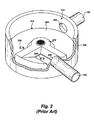
FIG. 2 is a perspective view of the upper chamber of a prior art separator tank. -
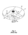
FIG. 3 is a perspective view of an insert for a prior art separator tank. -
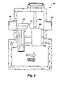
FIG. 4 is a cross-sectional view of a separator tank according to one embodiment of the present invention. -
FIG. 5 is a perspective view of the insert for a separator tank according to one embodiment of the present invention. -
Fig. 6 is a plan view of the insert for a separator tank according to one embodiment of the present invention. -
Fig. 7A - 7B is a plan and section view of an orifice plate located in the insert according to one embodiment of the present invention. -
Fig. 8 is a perspective view of the drop tube according to one embodiment of the present invention. -
Fig. 9 is a plan view of the drop tube according to one embodiment of the present invention. -
Fig. 10 is a longitudinal cross-section view of the drop tube according to one embodiment of the present invention. -
Fig. 11 is a front view of the drop tube according to one embodiment of the present invention. - Disclosed embodiments of the present invention and their advantages may be understood by referring to
Figs. 1 - 11 , wherein like reference numerals refer to like elements. - Referring to
Fig. 1 , a known separator tank, disclosed inU.S. Patent No. 5,498,331 , is illustrated.Separator tank 100 may generally be in the shape ofcontainer 102 havingbottom wall 104,side wall 106, andtop wall 108.Bottom wall 104 andtop wall 108 may generally be circular and flat.Side wall 106 may be substantially cylindrical.Bottom wall 104,side wall 106, andtop wall 108 may defineinternal chamber 110. In one embodiment, insert 112 may dividechamber 110 intoupper chamber 114 aboveinsert 112, andlower chamber 116 belowinsert 112. - Referring to
Fig. 2 , insert 112 hastop surface 208.Top surface 208 may generally be said to lie in a single horizontal plane, except forweir 210, which extends abovetop surface 208. In one embodiment,side wall 106 has inlet opening 200 located adjacently abovetop surface 208.Side wall 106 may also have outlet opening 206 located adjacently abovetop surface 208 and spaced peripherally away frominlet opening 200.Conduit 118 may be connected to inlet opening 200 through which liquid may be introduced into the separator tank. Further,conduit 120 may be connected tooutlet opening 206.Conduit 120 permits liquid to flow out of the separator tank. -
Insert 112 may include afirst opening 202. Opening 202 may be disposed between inlet opening 200 andweir 210. Asecond opening 204 may be on the outlet side ofweir 210.Openings weir 210, may flow through inlet opening 202 tooutlet opening 204. To do so, liquid first flows through inlet opening 202 into thelower chamber 116, throughlower chamber 116, and then up throughsecond opening 204 intoupper chamber 114. - Referring to
FIG. 3 , insert 112 may include adrop pipe 300 and ariser pipe 304. Droppipe 300 may be connected to and extend downwardly fromfirst opening 202. Droppipe 300 may have T-connection 302. T-connection 302 may allow for distributing the entering liquid in opposite directions withinlower chamber 116.Riser pipe 304 may be connected to and extend downwardly fromsecond opening 204.Riser pipe 304 permits water fromlower chamber 116 to flow upwardly intoupper chamber 114. - Referring now to
FIGS. 4 and5 ,separator tank 400 is shown according to one embodiment of the present invention. In addition to the features described above, in one embodiment,separator tank 400 includes various modifications and enhancements. These modifications and enhancements may include, for example, offsetting the position ofinsert 112 relative toinlet 118, increasing the height ofweir 412, modifyingfirst opening 202 to droptube 402, providing at least onevertical vane 410 indrop tube 402, modifying the base ofdrop tube 402, and modifying the back wall ofdrop tube 402. Each of these modifications may contribute to increasing the treatment flow rate throughseparator tank 400, while still maintaining high levels of separation and/or removal efficiency. Each modification will be described below. - Referring to
FIG. 5 , insert 112 is shown according to one embodiment of the present invention. In this embodiment, insert 112 may have a substantially circular outer perimeter, sized to fit within the cylindrical side wall ofseparator tank 400.Insert 112 may includeweir 412,first opening 202,orifice 502,drop pipe 402,riser pipe 404,second opening 408, and vent 406. In another embodiment, one or more of these elements may be provided separately. - Referring to
FIG. 6 , insert 112 may be positioned such thatweir 412 may be located betweeninlet 118 on one side ofseparator tank 400 andoutlet 120 on the other side. In one embodiment,weir 412 may define a substantially circular intake area for receiving influent liquid. In another embodiment,weir 412 may define a partially circular or semi-circular intake area. In still another embodiment,weir 412 may define a rectangular intake area. In still another embodiment,weir 412 may define a polygonal intake area. Theinsert 112 orweir 412 are positioned such thatweir 412 induces the influent liquid to flow in a swirling motion within the intake area. For example,weir 412 may be offset from the center line ofinlet 118 to induce swirling. In one embodiment,weir 412 may be offset from the center line ofinlet 118 by about 5°, as best shown inFIG. 6 . In this embodiment, as influent liquid enters the intake area, the influent liquid may have an angular momentum aboutorifice 502 causing the influent to swirl and form a controlled vortex. Further, in this embodiment, the influent liquid may form a controlled vortex consistently in the same direction during each flow event, which in turn may allowseparator tank 400 to handle increased flow rates. Moreover, the controlled vortex may ensure that all floatables, such as oil, are forced downdrop pipe 402. Other degrees of offset or positions forweir 412 may be used as necessary and/or desired. - In another embodiment,
inlet 118 may be tangential toseparator tank 400, thereby obviating the need to offsetinsert 112. In this embodiment, the shape ofweir 412 may be changed as necessary and/or desired to accommodate a tangential inlet. - In one embodiment, the height of
weir 412 may be increased relative to prior art separator weirs. Increasing the height ofweir 412 allows for the intake area to handle a greater flow rate. This embodiment leads to an increased pressure gradient, especially during high flow rates, that drives the liquid throughseparator tank 400. Further, the increased height ofweir 412 may allow for greater flow, which in turn may allow for the formation of a stronger and more controlled vortex. - Referring to
FIGS. 7A and 7B ,orifice 502 is shown according to one embodiment of the present invention.Orifice 502 is located in the intake area betweeninlet 118 andweir 412.Orifice 502 is positioned anywhere within the intake area. In one embodiment,orifice 502 createsfirst opening 202 through which influent liquid may enterdrop pipe 402. Theorifice 502 has a rounded entrance, as shown inFIG. 7B .Orifice 502 may generally be said to have two diameters: anoutside diameter 704 and aninside diameter 702. Outsidediameter 704 and insidediameter 702 may be sized appropriately for the environment in whichseparator tank 400 may be used. Outsidediameter 704 may be equivalent to where the rounded edge oforifice 502 aligns withtop surface 208 ofinsert 112. Theinside diameter 702 may be equivalent to where the rounded edge oforifice 502 aligns with the inside diameter ofdrop tube 402. In another embodiment, the diameter ofdrop tube 402 may be larger thaninside diameter 702. The diameters oforifice 502 may be changed as necessary and/or desired. - Rounding the entrance of
orifice 502 may increase the treatment flow rate tolower chamber 116. This increase in flow rate may be achieved because rounding the entrance oforifice 502 reduces the pressure drop of the liquid as it flows from aboveinsert 112 intodrop pipe 402. Further, rounding the edge oforifice 502 may prevent flow separation and resistance to flow. The radius of the rounded edge may be changed as necessary and/or desired. - Referring to
FIGS. 8-11 ,drop tube 402 is shown according to one embodiment. In this embodiment,drop tube 402 has a modified base and may include at least onevertical vane 410. Droptube 402 may be integrally formed withinsert 112 and extend into thelower chamber 116 ofseparator tank 400. - As shown in
FIG. 9 , droptube 402 may have a plurality ofvertical vanes 410 protruding from the inside wall ofdrop tube 402.Vertical vanes 410 serve to dissipate the vortex that is created in the intake area. As the influent liquid flows downward throughdrop tube 402,vertical vanes 410 create mini-vortices off the end of eachvane 410 that swirl in the opposite direction of the vortex. Thus,vertical vanes 410 dissipate the vortex and may create an equal distribution of flow withindrop tube 402.Vertical vanes 410 may also reduce the formation of eddies, which may lead to a more uniform velocity profile throughdrop tube 402. Reducing the high velocity jets may thereby reduce the chance of re-entraining any contaminates that have already accumulated inlower chamber 116. The shape, size, number, and/or location ofvertical vanes 410 may be changed as necessary and/or desired. - Referring to
FIG. 10 ,drop tube 402 is modified to terminate at a base that is comprised of twowings 806.Wings 806 extend outwardly fromdrop tube 402 and comprise the base fordrop tube 402. In one embodiment,wings 806 may extend in opposite directions. Droptube 402 has twoopenings 804 through which liquid exitsdrop tube 402 and enterslower chamber 116.Wings 806 are angled slightly downward to prevent solids from accumulated on the base.Wings 806 also prevent resuspension of contaminants already insidelower chamber 116. In one embodiment,wings 806 direct the flow of the influent liquid intolower chamber 116 in a perpendicular direction to that of the normal direction of flow inlower chamber 116. By introducing the influent liquid intolower chamber 116 in this manner, the residence time of the liquid inlower chamber 116 may be increased, and therefore the liquid may have an increased settling and separation time. - Referring to
FIGS. 10 and11 ,drop tube 402 has aback wall 810 andfront wall 808. In one embodiment, the arc length ofback wall 810 may be greater than the arc length offront wall 808. Modifying backwall 810 may prevent the influent liquid, as it exitsdrop tube 402, from impinging the nearest separator tank wall, which may be directly behinddrop tube 402. In this embodiment,back wall 810 may reduce re-entrainment and excessive turbulence. - The following examples are included to demonstrate preferred embodiments of the claimed subject matter. It should be appreciated by those of skill in the art that the techniques disclosed in the examples which follow represent techniques discovered by the inventors to function well in the practice of the claimed subject matter, and thus can be considered to constitute preferred modes for its practice. However, those of skill in the art should, in light of the present disclosure, appreciate that many changes can be made in the specific embodiments which are disclosed and still obtain a like or similar result without departing from the scope of the claimed subject matter.
- Example A separator tank with the modifications and enhancements described above was tested to illustrate the capture efficiency of sediment, for five (5) flows, at 100, 200 and 300 mg/L concentration per flow. The tested separator tank consisted of a 6-foot diameter by approximately 6-foot high upper receiving chamber and 8-foot diameter by approximately 6-foot high lower settling chamber. An insert was mounted within the separator tank. The insert incorporated a semi-circular weir, 11-inch orifice plate, 18-inch inlet drop tee, 24-inch vertical outlet riser-pipe and 6-inch oil port. The unit had a 24-inch diameter inlet and outlet pipes, with the inlet invert tangent to the insert floor and inlet to outlet differential of 1-inch. The inlet pipe was oriented with a 1% slope and both pipes are centered within the unit. The modifications and enhancements included offsetting the inlet by 5°, increasing the height of the weir, providing four vertical vanes in the drop tube, providing two wings at the base of the drop tube, and increasing the arc length of the back wall of the drop tube. The hydraulic capacity and sediment removal efficiency was evaluated for the separator tank.
- To determine the hydraulic capacity, preliminary flow (gpm) and water level (inches) within the unit were measured for 3 flows ranging from 0 to 1347 gpm (3.0 cfs). The maximum flow attained prior to breaching the bypass weir was 1122 gpm (2.5 cfs). Sediment removal efficiency tests were conducted at five (5) flows ranging from 281 to 1,403 gpm (0.63 to 3.13 cfs) with influent sediment concentrations of 100, 200 and 300 mg/L. The results are detailed below.
- During the testing, the sediment concentration in the influent was measured in two ways. First, the sediment concentration was measured directly by placing iso-kinetic samplers in the water stream and a sample was collected. Second, the sediment concentration was measured indirectly by weighing the mass of the sediment metered into the measured flow and a concentration was calculated. Effluent sediment concentration was measure using iso-kinetic samplers in the flow. Removal efficiency was calculated using the direct measurements for influent and effluent. Adjusted removal efficiency was calculated using the indirectly measure influent concentration and the directly measured effluent concentration.
- The average flow recorded for the entire test was 1400.7 gpm (3.12 cfs), with a standard deviation (SD) of 2.91. The recorded temperature for the test was 75.4 degrees F. The measured influent sample concentrations ranged from 253.8 mg/L to 349.1 mg/L, with a mean concentration of 284.9 mg/L and SD of 39.8. The effluent concentrations ranged from 162.9 mg/L to 182.6 mg/L, with a mean concentration of 174.1 mg/L and SD of 8.4. The average background concentration was 0.8 mg/L. The resulting sediment removal efficiency for the indirect method was 38.9%. The adjusted influent concentrations ranged from 300.1 mg/L to 311.5 mg/L, with a mean concentration of 304.2 mg/L and SD of 4.5. The corresponding adjusted removal efficiency was 42.8%.
- The average flow recorded for the entire test was 1401.4 gpm (3.12 cfs), with a standard deviation (SD) of 6.4. The recorded temperature for the test was 75.4 degrees F. The measured influent sample concentrations ranged from 177.8 mg/L to 220.0 mg/L, with a mean concentration of 196.3 mg/L and SD of 18.6. The effluent concentrations ranged from 122.1 mg/L to 139.2 mg/L, with a mean concentration of 132.3 mg/L and SD of 7.1. The average background concentration was 5.54 mg/L. The resulting sediment removal efficiency for the indirect method was 32.6%. The adjusted influent concentrations ranged from 199.1 mg/L to 204.0 mg/L, with a mean concentration of 201.8 mg/L and SD of 2.2. The corresponding adjusted removal efficiency was 34.4%.
- The average flow recorded for the entire test was 1401.1 gpm (3.12 cfs), with a standard deviation (SD) of 3.3. The recorded temperature for the test was 75.2 degrees F. The measured influent sample concentrations ranged from 78.3 mg/L to 115.1 mg/L, with a mean concentration of 97.1 mg/L and SD of 16.5. The effluent concentrations ranged from 79.8 mg/L to 88.9 mg/L, with a mean concentration of 84.0 mg/L and SD of 3.3. The average background concentration was 1.96 mg/L. The resulting sediment removal efficiency for the indirect method was 13.5%. The adjusted influent concentrations ranged from 98.1 mg/L to 98.7 mg/L, with a mean concentration of 98.4 mg/L and SD of 0.3. The corresponding adjusted removal efficiency was 14.6%.
- The average flow recorded for the entire test was 1122.0 gpm (2.50 cfs), with a standard deviation (SD) of 2.39. The recorded temperature for the test was 76.9 degrees F. The measured influent sample concentrations ranged from 241.5 mg/L to 368.0 mg/L, with a mean concentration of 297.5 mg/L and SD of 51.9. The effluent concentrations ranged from 105.5 mg/L to 132.6 mg/L, with a mean concentration of 120.4 mg/L and SD of 11.3. The average background concentration was negligible. The resulting sediment removal efficiency for the indirect method was 59.5%. The adjusted influent concentrations ranged from 98.5 mg/L to 306.8 mg/L, with a mean concentration of 304.2 mg/L and SD of 3.7. The corresponding adjusted removal efficiency was 60.4%.
- The average flow recorded for the entire test was 1121.6 gpm (2.50 cfs), with a standard deviation (SD) of 3.51. The recorded temperature for the test was 76.7 degrees F. The measured influent sample concentrations ranged from 157.9 mg/L to 253.2 mg/L, with a mean concentration of 190.1 mg/L and SD of 38.2. The effluent concentrations ranged from 72.3 mg/L to 86.9 mg/L, with a mean concentration of 80.4 mg/L and SD of 6.1. The average background concentration was 3.5 mg/L. The resulting sediment removal efficiency for the indirect method was 57.7%. The adjusted influent concentrations ranged from 197.4 mg/L to 203.1 mg/L, with a mean concentration of 201.1 mg/L and SD of 2.3. The corresponding adjusted removal efficiency was 60.0%.
- The average flow recorded for the entire test was 1118.3 gpm (2.49 cfs), with a standard deviation (SD) of 2.6. The recorded temperature for the test was 75.7 degrees F. The measured influent sample concentrations ranged from 100.8 mg/L to 121.8 mg/L, with a mean concentration of 110.3 mg/L and SD of 8.0. The effluent concentrations ranged from 46.8 mg/L to 62.0 mg/L, with a mean concentration of 55.9 mg/L and SD of 7.8. The average background concentration was negligible. The resulting sediment removal efficiency for the indirect method was 49.3%. The adjusted influent concentrations ranged from 98.5 mg/L to 99.4 mg/L, with a mean concentration of 99.0 mg/L and SD of 0.3. The corresponding adjusted removal efficiency was 43.5%.
- The average flow recorded for the entire test was 840.7 gpm (1.87 cfs), with a standard deviation (SD) of 2.2. The recorded temperature for the test was 77.9 degrees F. The measured influent sample concentrations ranged from 406.4 mg/L to 452.3 mg/L, with a mean concentration of 436.8 mg/L and SD of 18.9. The effluent concentrations ranged from 86.5 mg/L to 95.7 mg/L, with a mean concentration of 92.0 mg/L and SD of 3.4. The average background concentration was negligible. The resulting sediment removal efficiency for the indirect method was 78.9%. The adjusted influent concentrations ranged from 305.7 mg/L to 319.2 mg/L, with a mean concentration of 314.9 mg/L and SD of 4.9. The corresponding adjusted removal efficiency was 70.8%.
- The average flow recorded for the entire test was 842.4 gpm (1.88 cfs), with a standard deviation (SD) of 2.2. The recorded temperature for the test was 78.7 degrees F. The measured influent sample concentrations ranged from 256.2 mg/L to 290.4 mg/L, with a mean concentration of 276.4 mg/L and SD of 13.4. The effluent concentrations ranged from 56.7 mg/L to 79.9 mg/L, with a mean concentration of 73.4 mg/L and SD of 9.5. The average background concentration was 1.5 mg/L. The resulting sediment removal efficiency for the indirect method was 73.4%. The adjusted influent concentrations ranged from 198.7 mg/L to 205.5 mg/L, with a mean concentration of 202.8 mg/L and SD of 2.6. The corresponding adjusted removal efficiency was 63.8%.
- The average flow recorded for the entire test was 841.6 gpm (1.88 cfs), with a standard deviation (SD) of 2.03. The recorded temperature for the test was 76.5 degrees F. The measured influent sample concentrations ranged from 85.4 mg/L to 130.2 mg/L, with a mean concentration of 104.4 mg/L and SD of 18.7. The effluent concentrations ranged from 31.5 mg/L to 46.6 mg/L, with a mean concentration of 37.9 mg/L and SD of 6.4. The average background concentration was negligible. The resulting sediment removal efficiency for the indirect method was 63.7%. The adjusted influent concentrations ranged from 98.6 mg/L to 102.6 mg/L, with a mean concentration of 101.6 mg/L and SD of 1.5. The corresponding adjusted removal efficiency was 62.7%.
- The average flow recorded for the entire test was 560.2 gpm (1.25 cfs), with a standard deviation (SD) of 1.0. The recorded temperature for the test was 76.3 degrees F. The measured influent sample concentrations ranged from 287.1 mg/L to 375.5 mg/L, with a mean concentration of 339.6 mg/L and SD of 34.6. The effluent concentrations ranged from 82.8 mg/L to 97.9 mg/L, with a mean concentration of 91.5 mg/L and SD of 6.0. The average background concentration was negligible. The resulting sediment removal efficiency for the indirect method was 73.0%. The adjusted influent concentrations ranged from 298.7 mg/L to 317.0 mg/L, with a mean concentration of 311.7 mg/L and SD of 7.0. The corresponding adjusted removal efficiency was 70.6%.
- The average flow recorded for the entire test was 560.4 gpm (1.25 cfs), with a standard deviation (SD) of 1.2. The recorded temperature for the test was 76.6 degrees F. The measured influent sample concentrations ranged from 200.7 mg/L to 246.2 mg/L, with a mean concentration of 224.7 mg/L and SD of 16.8. The effluent concentrations ranged from 48.6 mg/L to 64.3 mg/L, with a mean concentration of 55.6 mg/L and SD of 7.0. The average background concentration was negligible. The resulting sediment removal efficiency for the indirect method was 75.2%. The adjusted influent concentrations ranged from 196.9 mg/L to 205.3 mg/L, with a mean concentration of 202.7 mg/L and SD of 3.1. The corresponding adjusted removal efficiency was 72.6%.
- The average flow recorded for the entire test was 558.3 gpm (1.24 cfs), with a standard deviation (SD) of 9.0. The recorded temperature for the test was 77.2 degrees F. The measured influent sample concentrations ranged from 100.8 mg/L to 122.4 mg/L, with a mean concentration of 114.8 mg/L and SD of 8.5. The effluent concentrations ranged from 25.9 mg/L to 29.4 mg/L, with a mean concentration of 28.1 mg/L and SD of 1.4. The average background concentration was negligible. The resulting sediment removal efficiency for the indirect method was 75.6%. The adjusted influent concentrations ranged from 100.8 mg/L to 102.5 mg/L, with a mean concentration of 101.5 mg/L and SD of 0.7. The corresponding adjusted removal efficiency was 72.4%.
- The average flow recorded for the entire test was 280.7 gpm (0.63 cfs), with a standard deviation (SD) of 0.4. The recorded temperature for the test was 75.6 degrees F. The measured influent sample concentrations ranged from 318.8 mg/L to 363.0 mg/L, with a mean concentration of 331.2 mg/L and SD of 18.3. The effluent concentrations ranged from 25.6 mg/L to 41.7 mg/L, with a mean concentration of 31.8 mg/L and SD of 7.4. The average background concentration was negligible. The resulting sediment removal efficiency for the indirect method was 90.4%. The adjusted influent concentrations ranged from 286.5 mg/L to 307.3 mg/L, with a mean concentration of 293.3 mg/L and SD of 9.2. The corresponding adjusted removal efficiency was 89.2%.
- The average flow recorded for the entire test was 280.9 gpm (0.63 cfs), with a standard deviation (SD) of 0.4. The recorded temperature for the test was 75.5 degrees F. The measured influent sample concentrations ranged from 200.9 mg/L to 234.4 mg/L, with a mean concentration of 216.8 mg/L and SD of 15.5. The effluent concentrations ranged from 13.2 mg/L to 21.8 mg/L, with a mean concentration of 16.0 mg/L and SD of 3.4. The average background concentration was negligible. The resulting sediment removal efficiency for the indirect method was 92.6%. The adjusted influent concentrations ranged from 189.1 mg/L to 193.7 mg/L, with a mean concentration of 193.3 mg/L and SD of 1.9. The corresponding adjusted removal efficiency was 91.7%.
- The average flow recorded for the entire test was 281.1 gpm (0.63 cfs), with a standard deviation (SD) of 0.4. The recorded temperature for the test was 75.4 degrees F. The measured influent sample concentrations ranged from 77.5 mg/L to 140.5 mg/L, with a mean concentration of 101.6 mg/L and SD of 24.4. The effluent concentrations ranged from 4.7 mg/L to 9.6 mg/L, with a mean concentration of 6.8 mg/L and SD of 2.2. The average background concentration was negligible. The resulting sediment removal efficiency for the indirect method was 93.3%. The adjusted influent concentrations ranged from 95.9 mg/L to 102.8 mg/L, with a mean concentration of 99.4 mg/L and SD of 3.2. The corresponding adjusted removal efficiency was 93.1%.
Claims (9)
- A separator tank (400), comprising:a container having a bottom wall, side wall, and top wall defining an internal chamber;an insert (112) located inside of the internal chamber and dividing the internal chamber into an upper chamber (114) and a lower chamber (116), the insert (112) comprising:a weir (412) defining an intake area between the weir and the side wall; andan orifice (502) positioned within the intake area;an inlet conduit (118) for introducing an influent liquid into the intake area; andwherein the weir (412) is positioned such that the weir (412) induces the influent liquid to flow in a swirling motion within the intake area,a drop tube (402) in fluid communication with the orifice (502) and extending into the lower chamber, the drop tube having two openings (804) through which liquid exits the drop tube to enter the lower chamber;wherein the drop tube (402) terminates at a base comprised by two wings (806) for directing the influent liquid into the lower chamber; the tank characterized in that:the orifice (502) has a rounded edge such that the diameter of the orifice (502) decreases in the direction of flow of liquid through the orifice (502);the two wings (806) are angled downward; andthe two wings (806) extend beyond the maximum circumference of the drop tube (402).
- The separator tank of claim 1, wherein the weir (412) is curved to form a substantially circular intake area.
- The separator tank of claim 1, wherein the weir (412) is offset from the center line of the inlet conduit (118) to position the weir (412) such that the swirling motion causes a controlled vortex to ensure that floatables are forced down the drop tube.
- The separator tank of claim 1, wherein the drop tube (402) comprises at least one vertical vane (410) to dissipate the swirling motion as the influent liquid flows through the drop tube (402).
- An insert (112) for a separator tank, the insert (112) comprising:a weir (412) defining an intake area for receiving an influent liquid; andan orifice (502) positioned within the intake area,wherein the insert (112) further comprises a drop tube (402) in fluid communication with the orifice (502) and extending below the insert (112), the drop tube having two openings (804) through which liquid exits the drop tube;wherein the drop tube (402) comprises a base formed by two wings (806) at the bottom of the openings (804); the insert characterized in that:said orifice (502) having a rounded edge such that the diameter of the orifice (502) decreases in the direction of flow of liquid through the orifice (502);the two wings (806) are angled downward from the openings (804); andthe two wings (806) extend beyond the maximum circumference of the drop tube (402).
- The insert (112) of claim 5, wherein the weir (412) is curved to form a substantially circular intake area.
- The insert of claim 5 wherein the drop tube (402) comprises at least one vertical vane (410).
- The separator tank of claim 3 comprising multiple vertical vanes (410) within the drop tube to dissipate the vortex as the influent liquid flows through the drop tube (402), wherein the length of one of the vertical vanes (410) differs from the length of the other vertical vane (410).
- The separator tank of claim 1 wherein the drop tube (402) further comprises a back wall (810) and front wall (808), the side wall of the container positioned behind the drop tube to locate the back wall nearer the side wall than the front wall, wherein the back wall (810) and the front wall (808) connect the drop tube (402) to the base, wherein the arc length of the back wall (810) is greater than the arc length of the front wall (808).
Priority Applications (1)
| Application Number | Priority Date | Filing Date | Title |
|---|---|---|---|
| PL08796285T PL2176171T3 (en) | 2007-07-20 | 2008-07-18 | Separator tank |
Applications Claiming Priority (3)
| Application Number | Priority Date | Filing Date | Title |
|---|---|---|---|
| US95099607P | 2007-07-20 | 2007-07-20 | |
| US11/942,049 US7666303B2 (en) | 2007-07-20 | 2007-11-19 | Seperator tank |
| PCT/US2008/070444 WO2009015010A1 (en) | 2007-07-20 | 2008-07-18 | Separator tank |
Publications (3)
| Publication Number | Publication Date |
|---|---|
| EP2176171A1 EP2176171A1 (en) | 2010-04-21 |
| EP2176171A4 EP2176171A4 (en) | 2012-08-22 |
| EP2176171B1 true EP2176171B1 (en) | 2016-01-27 |
Family
ID=40263982
Family Applications (1)
| Application Number | Title | Priority Date | Filing Date |
|---|---|---|---|
| EP08796285.8A Active EP2176171B1 (en) | 2007-07-20 | 2008-07-18 | Separator tank |
Country Status (10)
| Country | Link |
|---|---|
| US (1) | US7666303B2 (en) |
| EP (1) | EP2176171B1 (en) |
| JP (1) | JP5555160B2 (en) |
| KR (1) | KR101451593B1 (en) |
| AU (1) | AU2008279378B2 (en) |
| CA (1) | CA2694159C (en) |
| NZ (1) | NZ583008A (en) |
| PL (1) | PL2176171T3 (en) |
| WO (1) | WO2009015010A1 (en) |
| ZA (1) | ZA201000682B (en) |
Families Citing this family (23)
| Publication number | Priority date | Publication date | Assignee | Title |
|---|---|---|---|---|
| US7799235B2 (en) * | 2004-07-23 | 2010-09-21 | Contech Stormwater Solutions, Inc. | Fluid filter system and related method |
| US8123935B2 (en) * | 2007-08-15 | 2012-02-28 | Monteco Ltd. | Filter for removing sediment from water |
| US8287726B2 (en) | 2007-08-15 | 2012-10-16 | Monteco Ltd | Filter for removing sediment from water |
| US8221618B2 (en) * | 2007-08-15 | 2012-07-17 | Monteco Ltd. | Filter for removing sediment from water |
| FI120930B (en) * | 2008-09-19 | 2010-05-14 | Finnketju Invest Oy | Device in a liquid treatment room |
| JP5663209B2 (en) * | 2010-06-22 | 2015-02-04 | 株式会社イトーヨーギョー | Pollutant trapping structure and pollutant trapping facility |
| JP5936144B2 (en) * | 2010-09-09 | 2016-06-15 | ドレッサー ランド カンパニーDresser−Rand Company | Drain pipe controlled to be washable |
| KR101036944B1 (en) * | 2010-11-24 | 2011-05-25 | (주)덕산지에스 | Nonpoint Pollution Reduction Device |
| US8496810B2 (en) | 2011-05-04 | 2013-07-30 | Rainflex, Llc | Rainwater collection, storage, and distribution system |
| US9827510B2 (en) | 2014-12-08 | 2017-11-28 | Contech Engineered Solutions LLC | Hydrodynamic separator |
| CA3046647C (en) * | 2016-12-29 | 2023-08-22 | Contech Engineered Solutions LLC | Hydrodynamic separator |
| US10150063B2 (en) | 2016-12-29 | 2018-12-11 | Contech Engineered Solutions LLC | Hydrodynamic separator |
| US10309089B2 (en) * | 2017-02-24 | 2019-06-04 | Advanced Drainage Systems, Inc. | Liquid quality system with drag inducing portions |
| CN106948452A (en) * | 2017-04-17 | 2017-07-14 | 天津市水利科学研究院 | Catch-basin rain water pollutant cuts dirty facility and cuts dirty operating method |
| US10344466B2 (en) * | 2017-09-10 | 2019-07-09 | Bio Clean Environmental Services, Inc. | Hydrodynamic separator for stormwater treatment |
| US11041301B2 (en) | 2017-11-17 | 2021-06-22 | Advanced Drainage Systems, Inc. | Method for installing a liquid quality system |
| CN107916712B (en) * | 2017-12-13 | 2024-07-09 | 水利部杭州机械设计研究所 | Cyclone cut-off device |
| US10710907B2 (en) * | 2018-01-10 | 2020-07-14 | Hydroworks, Llc | Hydrodynamic separators, assemblies and methods for storm water treatment |
| KR101881848B1 (en) * | 2018-01-16 | 2018-07-25 | 황성규 | Apparatus for decreasing non-point pollution sources |
| US10953412B2 (en) | 2018-07-23 | 2021-03-23 | Contech Engineered Solutions LLC | Hydrodynamic separator |
| US11642610B2 (en) * | 2018-11-13 | 2023-05-09 | Leigh MAXWELL | Vortex inducing device and a method of use thereof for concentrating sediment in a water tank |
| US11033835B1 (en) | 2020-11-24 | 2021-06-15 | Advanced Drainage Systems, Inc. | Liquid quality system with drag-inducing portions |
| CN113018921B (en) * | 2021-02-26 | 2022-06-03 | 兰州理工大学 | Strong rotational flow forming device in limited fall |
Family Cites Families (55)
| Publication number | Priority date | Publication date | Assignee | Title |
|---|---|---|---|---|
| US942907A (en) | 1907-08-26 | 1909-12-14 | Packard Motor Car Co | Gasolene-tank for motor-vehicles. |
| US1237068A (en) | 1915-12-27 | 1917-08-14 | Nat Sanitary Service Company | Apparatus for recovering fat. |
| US1844443A (en) | 1931-09-28 | 1932-02-09 | Cincinnati Butchers Supply Co | Floor drain |
| US2393498A (en) | 1943-08-07 | 1946-01-22 | Firestone Tire & Rubber Co | Separator tank |
| US2689017A (en) * | 1951-06-02 | 1954-09-14 | J A Zurn Mfg Co | Surface drain |
| US2764545A (en) | 1953-11-02 | 1956-09-25 | Primich Theodore | Sectional septic tank |
| US3221881A (en) | 1962-05-25 | 1965-12-07 | Richard L Weiler | Glass fiber sewage tank |
| US3282436A (en) | 1963-06-17 | 1966-11-01 | Industrikemiska Ab | Combined by-pass and/or distribution sediment-thickening unit for sewage purificationplants |
| US3258123A (en) | 1963-08-22 | 1966-06-28 | Morgan Construction Co | Centripetal scale pit |
| US3374894A (en) | 1966-07-12 | 1968-03-26 | John D. Webster | Separating device for liquid fuel and water mixtures |
| US3567024A (en) | 1969-08-25 | 1971-03-02 | M J French Co Inc | Trench filter |
| US3822789A (en) | 1971-05-11 | 1974-07-09 | A Crisafulli | Oil skimmer module with free floating weir trough |
| US3951810A (en) | 1973-02-06 | 1976-04-20 | Crisafulli Angelo J | Oil skimmer module with free floating weir trough |
| US3862040A (en) | 1973-04-17 | 1975-01-21 | Paul Preus | Separator for liquids of different densities |
| NL167857C (en) | 1976-09-16 | 1982-02-16 | Chemap Ag | FILTERING DEVICE. |
| US4192751A (en) | 1977-06-15 | 1980-03-11 | Emerson Electric Co. | Bi-directional filter drier |
| US4127488A (en) | 1977-10-17 | 1978-11-28 | Ecodyne Corporation | Method and apparatus for separating solids from liquids |
| SE408195B (en) | 1978-03-02 | 1979-05-21 | Dunkers Karl Ragnar | DEVICE FOR EQUALIZATION OF DISCHARGES OF POLLUTED WATER IN A RECIPIENT |
| US4136010A (en) | 1978-04-05 | 1979-01-23 | Calspan Corporation | Catch basin interceptor |
| US4328101A (en) | 1980-06-17 | 1982-05-04 | Broden Carl V | Device for separating particulate matter from a fluid |
| US4363731A (en) | 1980-11-19 | 1982-12-14 | Rodolfo Filippi | Device for regulating the flow of waste waters |
| CH643022A5 (en) | 1981-09-01 | 1984-05-15 | Tartr Ex Sa | DEVICE FOR REGULATING THE FLOW OF WASTEWATER. |
| US4578188A (en) | 1985-07-26 | 1986-03-25 | Cousino Kenneth P | Sewerage flow diverter |
| US4693821A (en) | 1985-09-23 | 1987-09-15 | Transfield, Inc. | Weir for waste water treatment systems |
| US4722800A (en) * | 1986-05-30 | 1988-02-02 | Highland Tank And Manufacturing Company | Oil-water separator |
| FI94009C (en) | 1988-01-19 | 1995-07-10 | Yoshitomi Pharmaceutical | Biocidal 4,5-dichloro-1,2-dithiol-3-one composition |
| JPH065965Y2 (en) * | 1988-06-10 | 1994-02-16 | トヨタ車体株式会社 | Car body drain |
| GB2223957B (en) | 1988-10-07 | 1992-08-12 | Hydro Int Ltd | Separator |
| JPH035750U (en) * | 1989-06-07 | 1991-01-21 | ||
| US4985148A (en) | 1990-02-08 | 1991-01-15 | Fibresep Ltd. | Improved separator tank construction |
| HU209763B (en) | 1992-03-18 | 1994-10-28 | Szereday | Apparatus for separating first liquid contamination floating on fluid e.g. oil and the fluid e.g. water |
| DE59404144D1 (en) | 1993-07-28 | 1997-10-30 | Vsb Vogelsberger Umwelttechnis | Arrangement for removing contaminants, especially coarse materials, in partition structures for water protection, such as. B. rainwater relief structures |
| US5433845A (en) | 1994-06-03 | 1995-07-18 | Newberry Tanks & Equipment, Inc. | Flow control bypass basin apparatus |
| US5498331A (en) | 1994-11-08 | 1996-03-12 | 1137361 Ontario Limited | Tank interceptor |
| US5992641A (en) | 1995-06-05 | 1999-11-30 | Ecc International Inc. | Methods and apparatus for screening particulate materials |
| NZ313104A (en) | 1995-07-28 | 1999-11-29 | Univ Swinburne | Separator |
| US6540916B2 (en) | 1995-12-15 | 2003-04-01 | Microban Products Company | Antimicrobial sintered porous plastic filter |
| US5746911A (en) | 1997-01-13 | 1998-05-05 | Pank; Thomas E. | Apparatus for separating a light from a heavy fluid |
| CA2175277C (en) | 1996-04-29 | 1999-03-23 | Joseph Gordon Monteith | Enhanced separator tank |
| US5753115A (en) | 1996-07-09 | 1998-05-19 | Stormceptor Corporation | Submerged pipe separator tank |
| CA2195822C (en) | 1997-01-23 | 1999-10-12 | Joseph Gordon Monteith | Multicell separator |
| US5849181A (en) * | 1997-06-02 | 1998-12-15 | Stormceptor Corporation | Catch basin |
| US6062767A (en) * | 1998-02-09 | 2000-05-16 | Kizhnerman; Samuil | Storm water receptor system |
| US6524473B2 (en) * | 1998-04-01 | 2003-02-25 | J. Kelly Williamson | Gravitational separator and drainwater treatment system for use in a horizontal passageway |
| SE512069C2 (en) * | 1998-07-20 | 2000-01-24 | Bert Gustafsson | Device called chamber distribution insert, intended to be mounted in the joint between two concrete pipes for dividing the pipe body into several separate chambers |
| US6068765A (en) | 1999-03-26 | 2000-05-30 | Stormceptor Corporation | Separator tank |
| JP2000319979A (en) * | 1999-05-14 | 2000-11-21 | Ishikawajima Harima Heavy Ind Co Ltd | Multi-stage swirl head |
| JP4414067B2 (en) * | 2000-06-22 | 2010-02-10 | 株式会社イトーヨーギョー | Manhole fittings and manhole structures |
| US6428588B1 (en) | 2000-06-28 | 2002-08-06 | David Holyoak | Filter cleaning apparatus |
| US6371690B1 (en) | 2000-12-07 | 2002-04-16 | Joseph Gordon Monteith | Method and apparatus for handling water at low and high feed rates |
| US6547962B2 (en) * | 2001-06-27 | 2003-04-15 | Tec-Kon Enterprises, Llc | Stormwater treatment system |
| US20030141231A1 (en) * | 2002-01-30 | 2003-07-31 | Rattenbury John M. | Baffle insert for drains |
| US6866447B1 (en) | 2003-09-16 | 2005-03-15 | Alton F. Parker | Multi-use fluid collection and transport apparatus |
| US7182874B2 (en) * | 2004-02-20 | 2007-02-27 | Kristar Enterprises, Inc. | Storm water treatment apparatus employing dual vortex separators |
| US7314549B2 (en) * | 2006-04-14 | 2008-01-01 | Storm Pal Inc. | Storm water interceptor |
-
2007
- 2007-11-19 US US11/942,049 patent/US7666303B2/en active Active
-
2008
- 2008-07-18 JP JP2010518307A patent/JP5555160B2/en active Active
- 2008-07-18 NZ NZ583008A patent/NZ583008A/en unknown
- 2008-07-18 AU AU2008279378A patent/AU2008279378B2/en active Active
- 2008-07-18 WO PCT/US2008/070444 patent/WO2009015010A1/en not_active Ceased
- 2008-07-18 PL PL08796285T patent/PL2176171T3/en unknown
- 2008-07-18 KR KR1020107003721A patent/KR101451593B1/en not_active Expired - Fee Related
- 2008-07-18 EP EP08796285.8A patent/EP2176171B1/en active Active
- 2008-07-18 CA CA2694159A patent/CA2694159C/en active Active
-
2010
- 2010-01-28 ZA ZA201000682A patent/ZA201000682B/en unknown
Also Published As
| Publication number | Publication date |
|---|---|
| EP2176171A4 (en) | 2012-08-22 |
| AU2008279378A1 (en) | 2009-01-29 |
| EP2176171A1 (en) | 2010-04-21 |
| WO2009015010A1 (en) | 2009-01-29 |
| AU2008279378B2 (en) | 2012-10-04 |
| KR101451593B1 (en) | 2014-10-16 |
| JP2010534288A (en) | 2010-11-04 |
| US7666303B2 (en) | 2010-02-23 |
| KR20100075824A (en) | 2010-07-05 |
| ZA201000682B (en) | 2010-10-27 |
| CA2694159A1 (en) | 2009-01-29 |
| US20090020466A1 (en) | 2009-01-22 |
| PL2176171T3 (en) | 2016-07-29 |
| NZ583008A (en) | 2013-01-25 |
| JP5555160B2 (en) | 2014-07-23 |
| CA2694159C (en) | 2015-09-15 |
Similar Documents
| Publication | Publication Date | Title |
|---|---|---|
| US7666303B2 (en) | Seperator tank | |
| US7182874B2 (en) | Storm water treatment apparatus employing dual vortex separators | |
| US6547962B2 (en) | Stormwater treatment system | |
| US10710907B2 (en) | Hydrodynamic separators, assemblies and methods for storm water treatment | |
| EP3585497B1 (en) | Liquid quality system with drag inducing portions | |
| US20070267342A1 (en) | Apparatus for separating particulate from stormwater | |
| JP2010534288A5 (en) | ||
| US10662637B2 (en) | Inclined plates for CSO | |
| EP3033456B1 (en) | A separator module for a stormwater gully chamber | |
| US9695584B2 (en) | Inclined plates for CSO | |
| US20170240438A1 (en) | Liquid quality device with weir | |
| US20200009474A1 (en) | Systems and methods useful for efficient fluid run-off separation of liquid and solid contaminants | |
| US20060283814A1 (en) | Gravitational separator and apparatus for separating floating particulate and volatile liquids from a stormwater stream adaptable for inline usage | |
| EP0258359A1 (en) | Method of separating a medium in different components by means of gravity. | |
| US9458029B2 (en) | Separator for separating a light liquid-water mixture and method for separating a light liquid-water mixture | |
| US20230256361A1 (en) | Liquid quality system with drag-inducing portions | |
| JP3062561B2 (en) | Oil-water separator | |
| KR200288289Y1 (en) | Spiral separator | |
| JP3338391B2 (en) | Settling separation tank | |
| CA2216571C (en) | Improved oil/grit interceptor | |
| SU1727868A1 (en) | Liquid clarifier | |
| JPH0143589B2 (en) |
Legal Events
| Date | Code | Title | Description |
|---|---|---|---|
| PUAI | Public reference made under article 153(3) epc to a published international application that has entered the european phase |
Free format text: ORIGINAL CODE: 0009012 |
|
| 17P | Request for examination filed |
Effective date: 20100219 |
|
| AK | Designated contracting states |
Kind code of ref document: A1 Designated state(s): AT BE BG CH CY CZ DE DK EE ES FI FR GB GR HR HU IE IS IT LI LT LU LV MC MT NL NO PL PT RO SE SI SK TR |
|
| AX | Request for extension of the european patent |
Extension state: AL BA MK RS |
|
| DAX | Request for extension of the european patent (deleted) | ||
| A4 | Supplementary search report drawn up and despatched |
Effective date: 20120720 |
|
| RIC1 | Information provided on ipc code assigned before grant |
Ipc: C02F 1/00 20060101AFI20120716BHEP Ipc: E03F 5/14 20060101ALI20120716BHEP Ipc: B01D 21/24 20060101ALI20120716BHEP |
|
| RAP1 | Party data changed (applicant data changed or rights of an application transferred) |
Owner name: IMBRIUM INTERNATIONAL LIMITED |
|
| 17Q | First examination report despatched |
Effective date: 20130918 |
|
| GRAP | Despatch of communication of intention to grant a patent |
Free format text: ORIGINAL CODE: EPIDOSNIGR1 |
|
| INTG | Intention to grant announced |
Effective date: 20150716 |
|
| GRAS | Grant fee paid |
Free format text: ORIGINAL CODE: EPIDOSNIGR3 |
|
| GRAA | (expected) grant |
Free format text: ORIGINAL CODE: 0009210 |
|
| RAP1 | Party data changed (applicant data changed or rights of an application transferred) |
Owner name: IMBRIUM SYSTEMS INC. |
|
| AK | Designated contracting states |
Kind code of ref document: B1 Designated state(s): AT BE BG CH CY CZ DE DK EE ES FI FR GB GR HR HU IE IS IT LI LT LU LV MC MT NL NO PL PT RO SE SI SK TR |
|
| REG | Reference to a national code |
Ref country code: GB Ref legal event code: FG4D |
|
| REG | Reference to a national code |
Ref country code: CH Ref legal event code: EP |
|
| REG | Reference to a national code |
Ref country code: AT Ref legal event code: REF Ref document number: 772597 Country of ref document: AT Kind code of ref document: T Effective date: 20160215 |
|
| REG | Reference to a national code |
Ref country code: IE Ref legal event code: FG4D |
|
| REG | Reference to a national code |
Ref country code: DE Ref legal event code: R096 Ref document number: 602008042195 Country of ref document: DE |
|
| REG | Reference to a national code |
Ref country code: LT Ref legal event code: MG4D |
|
| REG | Reference to a national code |
Ref country code: NL Ref legal event code: MP Effective date: 20160127 |
|
| REG | Reference to a national code |
Ref country code: AT Ref legal event code: MK05 Ref document number: 772597 Country of ref document: AT Kind code of ref document: T Effective date: 20160127 |
|
| PG25 | Lapsed in a contracting state [announced via postgrant information from national office to epo] |
Ref country code: NL Free format text: LAPSE BECAUSE OF FAILURE TO SUBMIT A TRANSLATION OF THE DESCRIPTION OR TO PAY THE FEE WITHIN THE PRESCRIBED TIME-LIMIT Effective date: 20160127 |
|
| REG | Reference to a national code |
Ref country code: FR Ref legal event code: PLFP Year of fee payment: 9 |
|
| PG25 | Lapsed in a contracting state [announced via postgrant information from national office to epo] |
Ref country code: HR Free format text: LAPSE BECAUSE OF FAILURE TO SUBMIT A TRANSLATION OF THE DESCRIPTION OR TO PAY THE FEE WITHIN THE PRESCRIBED TIME-LIMIT Effective date: 20160127 Ref country code: GR Free format text: LAPSE BECAUSE OF FAILURE TO SUBMIT A TRANSLATION OF THE DESCRIPTION OR TO PAY THE FEE WITHIN THE PRESCRIBED TIME-LIMIT Effective date: 20160428 Ref country code: NO Free format text: LAPSE BECAUSE OF FAILURE TO SUBMIT A TRANSLATION OF THE DESCRIPTION OR TO PAY THE FEE WITHIN THE PRESCRIBED TIME-LIMIT Effective date: 20160427 Ref country code: ES Free format text: LAPSE BECAUSE OF FAILURE TO SUBMIT A TRANSLATION OF THE DESCRIPTION OR TO PAY THE FEE WITHIN THE PRESCRIBED TIME-LIMIT Effective date: 20160127 Ref country code: FI Free format text: LAPSE BECAUSE OF FAILURE TO SUBMIT A TRANSLATION OF THE DESCRIPTION OR TO PAY THE FEE WITHIN THE PRESCRIBED TIME-LIMIT Effective date: 20160127 |
|
| PG25 | Lapsed in a contracting state [announced via postgrant information from national office to epo] |
Ref country code: LT Free format text: LAPSE BECAUSE OF FAILURE TO SUBMIT A TRANSLATION OF THE DESCRIPTION OR TO PAY THE FEE WITHIN THE PRESCRIBED TIME-LIMIT Effective date: 20160127 Ref country code: IS Free format text: LAPSE BECAUSE OF FAILURE TO SUBMIT A TRANSLATION OF THE DESCRIPTION OR TO PAY THE FEE WITHIN THE PRESCRIBED TIME-LIMIT Effective date: 20160527 Ref country code: PT Free format text: LAPSE BECAUSE OF FAILURE TO SUBMIT A TRANSLATION OF THE DESCRIPTION OR TO PAY THE FEE WITHIN THE PRESCRIBED TIME-LIMIT Effective date: 20160527 Ref country code: SE Free format text: LAPSE BECAUSE OF FAILURE TO SUBMIT A TRANSLATION OF THE DESCRIPTION OR TO PAY THE FEE WITHIN THE PRESCRIBED TIME-LIMIT Effective date: 20160127 Ref country code: LV Free format text: LAPSE BECAUSE OF FAILURE TO SUBMIT A TRANSLATION OF THE DESCRIPTION OR TO PAY THE FEE WITHIN THE PRESCRIBED TIME-LIMIT Effective date: 20160127 Ref country code: AT Free format text: LAPSE BECAUSE OF FAILURE TO SUBMIT A TRANSLATION OF THE DESCRIPTION OR TO PAY THE FEE WITHIN THE PRESCRIBED TIME-LIMIT Effective date: 20160127 |
|
| REG | Reference to a national code |
Ref country code: DE Ref legal event code: R097 Ref document number: 602008042195 Country of ref document: DE |
|
| PG25 | Lapsed in a contracting state [announced via postgrant information from national office to epo] |
Ref country code: EE Free format text: LAPSE BECAUSE OF FAILURE TO SUBMIT A TRANSLATION OF THE DESCRIPTION OR TO PAY THE FEE WITHIN THE PRESCRIBED TIME-LIMIT Effective date: 20160127 Ref country code: DK Free format text: LAPSE BECAUSE OF FAILURE TO SUBMIT A TRANSLATION OF THE DESCRIPTION OR TO PAY THE FEE WITHIN THE PRESCRIBED TIME-LIMIT Effective date: 20160127 |
|
| PGFP | Annual fee paid to national office [announced via postgrant information from national office to epo] |
Ref country code: IE Payment date: 20160726 Year of fee payment: 9 |
|
| PG25 | Lapsed in a contracting state [announced via postgrant information from national office to epo] |
Ref country code: RO Free format text: LAPSE BECAUSE OF FAILURE TO SUBMIT A TRANSLATION OF THE DESCRIPTION OR TO PAY THE FEE WITHIN THE PRESCRIBED TIME-LIMIT Effective date: 20160127 Ref country code: SK Free format text: LAPSE BECAUSE OF FAILURE TO SUBMIT A TRANSLATION OF THE DESCRIPTION OR TO PAY THE FEE WITHIN THE PRESCRIBED TIME-LIMIT Effective date: 20160127 Ref country code: CZ Free format text: LAPSE BECAUSE OF FAILURE TO SUBMIT A TRANSLATION OF THE DESCRIPTION OR TO PAY THE FEE WITHIN THE PRESCRIBED TIME-LIMIT Effective date: 20160127 |
|
| PLBE | No opposition filed within time limit |
Free format text: ORIGINAL CODE: 0009261 |
|
| STAA | Information on the status of an ep patent application or granted ep patent |
Free format text: STATUS: NO OPPOSITION FILED WITHIN TIME LIMIT |
|
| PG25 | Lapsed in a contracting state [announced via postgrant information from national office to epo] |
Ref country code: BE Free format text: LAPSE BECAUSE OF FAILURE TO SUBMIT A TRANSLATION OF THE DESCRIPTION OR TO PAY THE FEE WITHIN THE PRESCRIBED TIME-LIMIT Effective date: 20160127 |
|
| 26N | No opposition filed |
Effective date: 20161028 |
|
| PG25 | Lapsed in a contracting state [announced via postgrant information from national office to epo] |
Ref country code: BG Free format text: LAPSE BECAUSE OF FAILURE TO SUBMIT A TRANSLATION OF THE DESCRIPTION OR TO PAY THE FEE WITHIN THE PRESCRIBED TIME-LIMIT Effective date: 20160427 Ref country code: SI Free format text: LAPSE BECAUSE OF FAILURE TO SUBMIT A TRANSLATION OF THE DESCRIPTION OR TO PAY THE FEE WITHIN THE PRESCRIBED TIME-LIMIT Effective date: 20160127 |
|
| REG | Reference to a national code |
Ref country code: CH Ref legal event code: PL |
|
| PG25 | Lapsed in a contracting state [announced via postgrant information from national office to epo] |
Ref country code: MC Free format text: LAPSE BECAUSE OF FAILURE TO SUBMIT A TRANSLATION OF THE DESCRIPTION OR TO PAY THE FEE WITHIN THE PRESCRIBED TIME-LIMIT Effective date: 20160127 |
|
| PG25 | Lapsed in a contracting state [announced via postgrant information from national office to epo] |
Ref country code: LI Free format text: LAPSE BECAUSE OF NON-PAYMENT OF DUE FEES Effective date: 20160731 Ref country code: CH Free format text: LAPSE BECAUSE OF NON-PAYMENT OF DUE FEES Effective date: 20160731 |
|
| REG | Reference to a national code |
Ref country code: FR Ref legal event code: PLFP Year of fee payment: 10 |
|
| PG25 | Lapsed in a contracting state [announced via postgrant information from national office to epo] |
Ref country code: LU Free format text: LAPSE BECAUSE OF NON-PAYMENT OF DUE FEES Effective date: 20160718 |
|
| REG | Reference to a national code |
Ref country code: IE Ref legal event code: MM4A |
|
| PG25 | Lapsed in a contracting state [announced via postgrant information from national office to epo] |
Ref country code: IE Free format text: LAPSE BECAUSE OF NON-PAYMENT OF DUE FEES Effective date: 20170718 |
|
| PG25 | Lapsed in a contracting state [announced via postgrant information from national office to epo] |
Ref country code: HU Free format text: LAPSE BECAUSE OF FAILURE TO SUBMIT A TRANSLATION OF THE DESCRIPTION OR TO PAY THE FEE WITHIN THE PRESCRIBED TIME-LIMIT; INVALID AB INITIO Effective date: 20080718 Ref country code: CY Free format text: LAPSE BECAUSE OF FAILURE TO SUBMIT A TRANSLATION OF THE DESCRIPTION OR TO PAY THE FEE WITHIN THE PRESCRIBED TIME-LIMIT Effective date: 20160127 |
|
| PG25 | Lapsed in a contracting state [announced via postgrant information from national office to epo] |
Ref country code: TR Free format text: LAPSE BECAUSE OF FAILURE TO SUBMIT A TRANSLATION OF THE DESCRIPTION OR TO PAY THE FEE WITHIN THE PRESCRIBED TIME-LIMIT Effective date: 20160127 Ref country code: MT Free format text: LAPSE BECAUSE OF NON-PAYMENT OF DUE FEES Effective date: 20160731 |
|
| REG | Reference to a national code |
Ref country code: FR Ref legal event code: PLFP Year of fee payment: 11 |
|
| PGFP | Annual fee paid to national office [announced via postgrant information from national office to epo] |
Ref country code: FR Payment date: 20210726 Year of fee payment: 14 |
|
| PGFP | Annual fee paid to national office [announced via postgrant information from national office to epo] |
Ref country code: PL Payment date: 20210701 Year of fee payment: 14 Ref country code: DE Payment date: 20210728 Year of fee payment: 14 |
|
| REG | Reference to a national code |
Ref country code: DE Ref legal event code: R119 Ref document number: 602008042195 Country of ref document: DE |
|
| PG25 | Lapsed in a contracting state [announced via postgrant information from national office to epo] |
Ref country code: FR Free format text: LAPSE BECAUSE OF NON-PAYMENT OF DUE FEES Effective date: 20220731 |
|
| PG25 | Lapsed in a contracting state [announced via postgrant information from national office to epo] |
Ref country code: DE Free format text: LAPSE BECAUSE OF NON-PAYMENT OF DUE FEES Effective date: 20230201 |
|
| PG25 | Lapsed in a contracting state [announced via postgrant information from national office to epo] |
Ref country code: PL Free format text: LAPSE BECAUSE OF NON-PAYMENT OF DUE FEES Effective date: 20220718 |
|
| PGFP | Annual fee paid to national office [announced via postgrant information from national office to epo] |
Ref country code: IT Payment date: 20250721 Year of fee payment: 18 |
|
| PGFP | Annual fee paid to national office [announced via postgrant information from national office to epo] |
Ref country code: GB Payment date: 20250728 Year of fee payment: 18 |