EP2175807B1 - Humeral prosthesis - Google Patents
Humeral prosthesis Download PDFInfo
- Publication number
- EP2175807B1 EP2175807B1 EP08776320A EP08776320A EP2175807B1 EP 2175807 B1 EP2175807 B1 EP 2175807B1 EP 08776320 A EP08776320 A EP 08776320A EP 08776320 A EP08776320 A EP 08776320A EP 2175807 B1 EP2175807 B1 EP 2175807B1
- Authority
- EP
- European Patent Office
- Prior art keywords
- articulation
- prosthesis
- insert
- humeral
- rotation
- Prior art date
- Legal status (The legal status is an assumption and is not a legal conclusion. Google has not performed a legal analysis and makes no representation as to the accuracy of the status listed.)
- Active
Links
Images

Classifications
-
- A—HUMAN NECESSITIES
- A61—MEDICAL OR VETERINARY SCIENCE; HYGIENE
- A61F—FILTERS IMPLANTABLE INTO BLOOD VESSELS; PROSTHESES; DEVICES PROVIDING PATENCY TO, OR PREVENTING COLLAPSING OF, TUBULAR STRUCTURES OF THE BODY, e.g. STENTS; ORTHOPAEDIC, NURSING OR CONTRACEPTIVE DEVICES; FOMENTATION; TREATMENT OR PROTECTION OF EYES OR EARS; BANDAGES, DRESSINGS OR ABSORBENT PADS; FIRST-AID KITS
- A61F2/00—Filters implantable into blood vessels; Prostheses, i.e. artificial substitutes or replacements for parts of the body; Appliances for connecting them with the body; Devices providing patency to, or preventing collapsing of, tubular structures of the body, e.g. stents
- A61F2/02—Prostheses implantable into the body
- A61F2/30—Joints
- A61F2/40—Joints for shoulders
-
- A—HUMAN NECESSITIES
- A61—MEDICAL OR VETERINARY SCIENCE; HYGIENE
- A61F—FILTERS IMPLANTABLE INTO BLOOD VESSELS; PROSTHESES; DEVICES PROVIDING PATENCY TO, OR PREVENTING COLLAPSING OF, TUBULAR STRUCTURES OF THE BODY, e.g. STENTS; ORTHOPAEDIC, NURSING OR CONTRACEPTIVE DEVICES; FOMENTATION; TREATMENT OR PROTECTION OF EYES OR EARS; BANDAGES, DRESSINGS OR ABSORBENT PADS; FIRST-AID KITS
- A61F2/00—Filters implantable into blood vessels; Prostheses, i.e. artificial substitutes or replacements for parts of the body; Appliances for connecting them with the body; Devices providing patency to, or preventing collapsing of, tubular structures of the body, e.g. stents
- A61F2/02—Prostheses implantable into the body
- A61F2/30—Joints
- A61F2/40—Joints for shoulders
- A61F2/4014—Humeral heads or necks; Connections of endoprosthetic heads or necks to endoprosthetic humeral shafts
-
- A—HUMAN NECESSITIES
- A61—MEDICAL OR VETERINARY SCIENCE; HYGIENE
- A61F—FILTERS IMPLANTABLE INTO BLOOD VESSELS; PROSTHESES; DEVICES PROVIDING PATENCY TO, OR PREVENTING COLLAPSING OF, TUBULAR STRUCTURES OF THE BODY, e.g. STENTS; ORTHOPAEDIC, NURSING OR CONTRACEPTIVE DEVICES; FOMENTATION; TREATMENT OR PROTECTION OF EYES OR EARS; BANDAGES, DRESSINGS OR ABSORBENT PADS; FIRST-AID KITS
- A61F2/00—Filters implantable into blood vessels; Prostheses, i.e. artificial substitutes or replacements for parts of the body; Appliances for connecting them with the body; Devices providing patency to, or preventing collapsing of, tubular structures of the body, e.g. stents
- A61F2/02—Prostheses implantable into the body
- A61F2/30—Joints
- A61F2/40—Joints for shoulders
- A61F2/4014—Humeral heads or necks; Connections of endoprosthetic heads or necks to endoprosthetic humeral shafts
- A61F2002/4018—Heads or epiphyseal parts of humerus
- A61F2002/4022—Heads or epiphyseal parts of humerus having a concave shape, e.g. hemispherical cups
-
- A—HUMAN NECESSITIES
- A61—MEDICAL OR VETERINARY SCIENCE; HYGIENE
- A61F—FILTERS IMPLANTABLE INTO BLOOD VESSELS; PROSTHESES; DEVICES PROVIDING PATENCY TO, OR PREVENTING COLLAPSING OF, TUBULAR STRUCTURES OF THE BODY, e.g. STENTS; ORTHOPAEDIC, NURSING OR CONTRACEPTIVE DEVICES; FOMENTATION; TREATMENT OR PROTECTION OF EYES OR EARS; BANDAGES, DRESSINGS OR ABSORBENT PADS; FIRST-AID KITS
- A61F2/00—Filters implantable into blood vessels; Prostheses, i.e. artificial substitutes or replacements for parts of the body; Appliances for connecting them with the body; Devices providing patency to, or preventing collapsing of, tubular structures of the body, e.g. stents
- A61F2/02—Prostheses implantable into the body
- A61F2/30—Joints
- A61F2/40—Joints for shoulders
- A61F2/4014—Humeral heads or necks; Connections of endoprosthetic heads or necks to endoprosthetic humeral shafts
- A61F2002/4037—Connections of heads to necks
Definitions
- the present invention concerns a humeral prosthesis for the articulation of a shoulder.
- the present invention is advantageously applied to a so-called inverse prosthesis, in which a convex-shaped head, or glenosphere, is associated with the glenoid seating of the shoulder and articulates in a concave artificial seating associated with the top of the humerus.
- the present invention is also applied to a normal or anatomical prosthesis, in which a substantially semi-spherical head is associated with the humerus and articulates in a mating concave seating, natural or artificial, associated with the glenoid seating.
- Prostheses of the shoulder which have a first articulation element associated with the meta-epiphysary part of the humerus, and a second articulation element associated with the shoulder.
- inverse prostheses which reproduce the gleno-humeral anatomy in an inverse manner, in which there is a humeral cup or insert of the concave type, inserted into the meta-epiphysary part of the humerus, which is able to articulate with a convex element, or glenosphere, fixed to the scapula.
- inverse prostheses are used in cases of serious muscular degeneration of the shoulder, particularly of the rotator cuff muscles.
- a fundamental requisite for a prosthesis is that it allows a good articular stability.
- an incorrect positioning of the components of the prosthesis can cause articular instability and contact between the humeral prosthesis and the scapula, with consequent wear of the bone, in the movement of rotation or adduction.
- inverse prostheses for the shoulder are positioned with zero retroversion, or a low level of retroversion, of the humerus; the first solution increases the risk of rear scapular notch, the second in any case introduces problems of articular instability and impingement with the shoulder.
- Purpose of the present invention is to achieve a humeral prosthesis which, once implanted, has the capacity to center itself according to the dynamic conditions of the shoulder-humerus combination, so as to guarantee articular stability, make movements more simple and physiological, and to improve the overall efficiency and the duration over time of the prosthesis.
- a humeral prothesis according to the preamble of claim 1 is known from the U.S. patent application US 2005/0165490 .
- the Applicant has devised, tested and embodied the present invention to overcome the shortcomings of the state of the art and to obtain these and other purposes and advantages.
- the present invention is applied both to an inverse prosthesis and also to a normal or anatomical prosthesis, for the articulation of a humerus in a scapula of a shoulder having a glenoid cavity.
- a humeral prosthesis according to the present invention comprises an articulation device able to be associated both with an articulation element, mounted on the glenoid cavity, and also with the top of the humerus by means of suitable attachment means, as defined in claim 1.
- the pivoting axis advantageously coincides with the so-called diaphysis axis defined by the humerus and therefore said pivoting allows the free rotation of the first and second element of the articulation device particularly in the movements of intra-rotation and extra-rotation.
- the pivoting axis can be parallel but not coincident with the diaphysis axis.
- pivoting axis is inclined by a pre-determined angle with respect to said diaphysis axis, again in order to meet particular needs.
- the articulation element is of the convex type, the so-called glenosphere, and the first element is consequently of the concave type, the so-called humeral cup.
- the articulation element is of the concave type, the so-called glenoid cavity, artificial or natural, and the first element is consequently of the convex type, the so-called humeral head.
- the humeral prosthesis once implanted, has the capacity to center itself according to the dynamic conditions of the shoulder-humerus combination, dynamically moving to the optimum orientation between the humeral component and the glenoid component, guaranteeing articular stability and making movements more simple and physiological, advantageously the movements of intra-rotation and extra-rotation.
- the present invention reduces or eliminates the risks of wear on the bone due to rubbing between the shoulder and components of the prosthesis, thus improving the overall efficiency and the duration in time of the prosthesis.
- the present invention provides that the movements of intra-rotation and extra-rotation of the humerus are entrusted to the pivoting of the first and the second element of the articulation device, thus freeing the articular coupling of the shoulder and the articulation device from this task.
- the present invention provides that the relative rotation allowed by the pivoting of the first element and the second element is limited to a pre-determined angle of rotation.
- the first element and the second element have respectively a convex portion and a concave portion, able to couple with each other.
- the surfaces of the convex and concave portions are shaped so as to be at least partly complementary with each other, in order to define substantially congruent abutment walls which cooperate in a determinate angular interval and to function, they too, as elements to limit the rotation.
- the humerus is free to rotate around the pivoting axis, centering itself and adapting on each occasion to the dynamic balance that is established, in the determinate angular range, around the pivoting between the first element and the second element of the articulation device.
- any further intra-rotation or extra-rotation determines the start of the normal articulation between the humeral component and the glenoid component of the prosthesis.
- the present invention allows to position the humeral component with a low degree of retroversion, in order to increase the degree of intra-rotation, also eliminating the known problems in said solution of articular instability and impingement with the shoulder.
- the present invention applied to a normal or anatomical prosthesis, allows to reduce the risk of wear on the bone tissue due to rubbing of one part of the prosthesis against the shoulder, during the movements of rotation, particularly intra-rotation and extra-rotation.
- the attachment means to attach the articulation device, particularly its second element, to the humerus consists of a shaft fixed to said second element, which is connected to the meta-epiphysiary part of the humerus.
- the attachment means is made in a single piece with said second element of the articulation device, for example by extending in a suitable manner the lower part of the second element, or by adopting other attachment solutions.
- an inverse humeral prosthesis 10 comprises an articulation device 15 which is able to articulate with a corresponding glenosphere 12 made of polyethylene, fixed in the glenoid cavity, and to be fixed to the meta-epiphysary part of the humerus.
- the articulation device 15 comprises an insert 16, made of polyethylene, pivoted around a pivoting axis Y to a humeral body 18, made of a cobalt-based alloy.
- the device 15 also typically contains a connecting shaft 20 made of a titanium-based alloy, coaxial with the axis Y and fixed to the lower part of the humeral body 18.
- the shaft 20 has an end 19 with a determinate taper, for conical coupling with the humeral body 18.
- the shaft 20 is able to be connected to the meta-epiphysary part of the humerus, so as to connect the articulation device 15 with the humerus.
- the axis Y thus represents the axis around which the movements of intra-rotation and extra-rotation of the humerus take place.
- a rotation pin 22 is provided which functions as a rotation guide between the insert 16 and the humeral body 18, so that the whole is aligned with the axis Y, and which prevents the deformation of the polyethylene which makes up the insert 16.
- the pin 22 is able to be screwed into a seating 23 made on the end 19 of the shaft 20.
- the insert 16 and the humeral body 18 have reciprocally complementary or congruent shapes, so as to be able to be coupled rotationally.
- the insert 16 and the humeral body 18 are represented individually respectively in figs. 4 and 5 and in figs. 6 and 7 .
- both the insert 16 and the humeral body 18 have the shape of a flared cup, one of a size slightly different from the other, which develop around the axis Y.
- the humeral body 18 has lateral walls 38 which delimit internally a concave seating 28 to locate the insert 16.
- the walls 38 are suitably shaped so as to have a curvilinear development around the axis Y and so as to be, axially, substantially vertical or slightly inclined and flared.
- the humeral body 18 is provided at the lower part with a protuberance 31, in which a longitudinal through cavity 29 is made. In the through cavity 29 the conical coupling with the end 19 of the shaft 20 occurs.
- the particular solution shown of the humeral body 18 is a cup cut transversely along an inclined plane as can be seen in fig. 7 , and with a barrier element, or containing edge 21, which has the function of at least partly covering the polyethylene and prevent or reduce the filling by fibrous tissue of the cavities and interstices of the device 15, once the prosthesis 10 has been implanted.
- the insert 16 on an upper side, has a concave seating, or humeral seating 24, in which an articulation platelet 14 is housed and fixed ( figs. 3 , 8 and 9 ), made of an alloy based on cobalt, or titanium or ceramic, which during the normal use of the prosthesis 10 is interposed between the insert 16 and the glenosphere 12.
- the platelet 14 mainly functions as an articulation interface between the device 15 and the glenosphere 12.
- the platelet 14 has a concave external surface 39 ( figs. 3 , 8, 9 and 10 ) suitably shaped, for articulation with the glenosphere 12.
- the platelet 14 has cylindrical pins 35, with a stabilizing function under load, inserted freely or with interference into the holes of the insert 16, to prevent accidental dis-assembly.
- the presence of the platelet 14 is advantageous since, being made of metal, it determines a metal-plastic contact which allows the correct articulation of the polyethylene glenosphere 12 which otherwise would have to articulate on the insert 16, also made of polyethylene, with dangerous results for the articulation itself.
- the platelet 14 is made of a material suitable for articulation with the glenosphere 12.
- the platelet 14 also has the function, known for example from the patent application UD2004A000194 in the name of the present Applicant, of preventing or at least limiting the phenomenon of scapular notch, thanks to the anti-wear properties of the material of which it is made.
- the insert 16 has a convex portion 26, suitable to be inserted rotatably into the concave seating 28 of the humeral body 18.
- the convex portion 26 has a lateral surface 36, shaped so as to have a curvilinear development around the axis Y, coherent with the shaping of the walls 38 of the seating 28 and, on the side opposite the seating 24, has a protuberance 17 which is inserted into the through cavity 29 of the humeral body 18.
- the protuberance 17 has an annular attachment tooth 33 able to cooperate with a corresponding attachment portion 34 of the cavity 29, to achieve a snap-in attachment and prevent an unwanted axial uncoupling of the insert 16 and the humeral body 18.
- the protuberance 17 of the convex portion 26 has a through hole 25, through which said rotation pin 22 is inserted.
- the pin 22 is inserted into the through cavity 29 and screwed into the seating 23 of the shaft 20.
- the pin 22 thus abuts axially with an abutment portion 32, on the bottom of the seating 28.
- the insert 16 is housed rotatably in the seating 28 of the humeral body 18, taking care that the pin 22 also passes through the hole 25 made along the protuberance 17 of the insert 16.
- the pin 22 does not interfere in rotation with the insert 16 or with the platelet 14. Therefore, the shaft 20, the pin 22 and the humeral body 18 are solidly associated with each other and are rotatable around the axis Y, with respect to the insert 16, in movements of intra-rotation and extra-rotation, as indicated by the arrow R in figs. 1 and 2 .
- the rotation of the insert 16 and the humeral body 18 is limited to a determinate angular sector 27.
- the lateral surface 36 and the walls 38 are suitably shaped in a complementary manner with respect to each other.
- the lateral surface 36 of the insert 16 is axially flared, in a manner congruent with the walls 38 of the humeral body 18, with a slightly variable thickness or cross section.
- the surface 36 is substantially vertical with a constant section.
- the development in cross section, that is, around the axis Y, of the surface 36 and the walls 38 is substantially defined by two convergent segments, which can be rectilinear, concave or convex according to needs, and connected by a central curvilinear segment, as can be seen in figs. 5 and 6 .
- Both the surfaces 36 and the walls 38 are suitably beveled and joined, so as not to cause points of discontinuity or steps, which could impede the fluidity and naturalness of rotation.
- the walls 38 abut on the corresponding surface 36 of the insert 16, limiting the rotation.
- the surface 36 of the insert 16 thus constitutes an abutment portion and an impediment to the further rotation of the humeral body 18.
- the section or thickness of the walls 38 is variable, increasing from the center towards the periphery, following the greater transverse inclination of the humeral body 18.
- a geometry of the seating 28 is defined which delimits the determinate angular sector 27, as can be seen in fig. 6 .
- the humeral body 18 is thus free to rotate, in a clockwise or anti-clockwise direction, in this determinate angular sector 27 which, in this case, has an amplitude of about 60°, that is, between +30° and -30°.
- Figs. 11 and 12 show as a variant the application of the present invention to a normal or anatomical prosthesis 110, in which the same reference numbers are used for parts equal to those of the solution shown in figs. 1 to 10 .
- the prosthesis 110 unlike the prosthesis 10, provides that an artificial concave glenoid seating made of polyethylene, not shown here, is mounted on the glenoid cavity, whereas the articulation device 15 shown above is mounted on the humerus, in which, however, instead of the articulation platelet 14 an articulation member 114 is provided, at least partly convex.
- the member 114 is formed by an at least partly spherical head 214, of shape and size coherent with the artificial glenoid seating for articulation therewith, and by a support element 314 by means of which the head 214 is connected to the insert 16.
- the support element 314 is coupled with the insert 16 substantially in the same way as the platelet 14 and the insert 16 are coupled, as already described.
- the support element 314 is connected to the head 214 by conical coupling of a conical part thereof with a mating cavity 414 of the head 214.
- At least the head 214 is preferably made of cobalt-based alloy, for an effective articulation with the artificial glenoid seating.
- the prosthesis according to the present invention can be configured both as an inverse prosthesis 10 and also as a normal prosthesis 110, simply by changing the articulation platelet 14 with the articulation member 114.
- the platelet 14, the articulation member 114 and the humeral body 18 can be made, at least partly, of a metal alloy based on titanium subjected to surface treatments of hardening, such as nitriding.
Landscapes
- Health & Medical Sciences (AREA)
- Orthopedic Medicine & Surgery (AREA)
- Cardiology (AREA)
- Oral & Maxillofacial Surgery (AREA)
- Transplantation (AREA)
- Engineering & Computer Science (AREA)
- Biomedical Technology (AREA)
- Heart & Thoracic Surgery (AREA)
- Vascular Medicine (AREA)
- Life Sciences & Earth Sciences (AREA)
- Animal Behavior & Ethology (AREA)
- General Health & Medical Sciences (AREA)
- Public Health (AREA)
- Veterinary Medicine (AREA)
- Prostheses (AREA)
- Materials For Medical Uses (AREA)
Description
- The present invention concerns a humeral prosthesis for the articulation of a shoulder.
- The present invention is advantageously applied to a so-called inverse prosthesis, in which a convex-shaped head, or glenosphere, is associated with the glenoid seating of the shoulder and articulates in a concave artificial seating associated with the top of the humerus.
- The present invention is also applied to a normal or anatomical prosthesis, in which a substantially semi-spherical head is associated with the humerus and articulates in a mating concave seating, natural or artificial, associated with the glenoid seating.
- Prostheses of the shoulder are known, which have a first articulation element associated with the meta-epiphysary part of the humerus, and a second articulation element associated with the shoulder.
- In particular, in the case of anatomical or normal prostheses, there is a substantially semi-spherical head, mounted on the humerus, which articulates in a mating concave seating, natural or artificial, associated with the glenoid seating of the scapula.
- It is also known to use inverse prostheses, which reproduce the gleno-humeral anatomy in an inverse manner, in which there is a humeral cup or insert of the concave type, inserted into the meta-epiphysary part of the humerus, which is able to articulate with a convex element, or glenosphere, fixed to the scapula.
- Normally, inverse prostheses are used in cases of serious muscular degeneration of the shoulder, particularly of the rotator cuff muscles.
- A fundamental requisite for a prosthesis, whether anatomical or inverse, is that it allows a good articular stability.
- Obtaining a good articular stability, apart from the correct positioning of the elements of the prosthesis, which must be identified by the surgeon in an area of very limited size, also depends on the residual rotator cuff muscles and on the articular capsule. In fact, it is necessary to establish, artificially, a dynamic balance with the components of the prosthesis which allows, as much as possible, to recover the normal physiological functions of the shoulder-humerus articulation and which, however, it is difficult to provide.
- In both anatomical prostheses and in inverse prostheses, an incorrect positioning of the components of the prosthesis can cause articular instability and contact between the humeral prosthesis and the scapula, with consequent wear of the bone, in the movement of rotation or adduction.
- In particular, in anatomical prostheses there may be a risk of wear of the bone tissue due to the rubbing of a part of the prosthesis with the shoulder during the movements of rotation, particularly intra-rotation and extra-rotation.
- In inverse prostheses, on the contrary, the typical medialization of the humerus can cause articular instability, which affects 10% of operations, due to the non-appropriate anatomical coupling typical of such prostheses.
- In inverse prostheses, we also have the problem of the "scapular notch", due to the wear of the material which constitutes the humeral cup which rubs against the scapula, mainly at the bottom but also at the rear, and the consequent osteolysis of the glenoid.
- Normally, to limit some of these problems, inverse prostheses for the shoulder are positioned with zero retroversion, or a low level of retroversion, of the humerus; the first solution increases the risk of rear scapular notch, the second in any case introduces problems of articular instability and impingement with the shoulder.
- All in all, therefore, the positioning of the prostheses, both anatomical and inverse, has the problem that the optimum orientation between the humeral component and the glenoid component is always given, or that this orientation is not known in advance.
- This entails a compromise choice between articular stability, to be provided as far as possible according to the dynamic balance described above, and the risk of knocking and rubbing against the shoulder.
- This often prevents the prosthesis from being positioned in an optimum manner, and consequently introduces risk factors of articular instability, impediment to certain movements, knocking and rubbing.
- Purpose of the present invention is to achieve a humeral prosthesis which, once implanted, has the capacity to center itself according to the dynamic conditions of the shoulder-humerus combination, so as to guarantee articular stability, make movements more simple and physiological, and to improve the overall efficiency and the duration over time of the prosthesis.
- A humeral prothesis according to the preamble of claim 1 is known from the U.S. patent application
US 2005/0165490 . - The Applicant has devised, tested and embodied the present invention to overcome the shortcomings of the state of the art and to obtain these and other purposes and advantages.
- The present invention is set forth and characterized in the independent claim, while the dependent claims describe other characteristics of the invention or variants to the main inventive idea.
- The present invention is applied both to an inverse prosthesis and also to a normal or anatomical prosthesis, for the articulation of a humerus in a scapula of a shoulder having a glenoid cavity.
- In accordance with the above purpose, a humeral prosthesis according to the present invention comprises an articulation device able to be associated both with an articulation element, mounted on the glenoid cavity, and also with the top of the humerus by means of suitable attachment means, as defined in claim 1.
- In a variant of the invention, the pivoting axis advantageously coincides with the so-called diaphysis axis defined by the humerus and therefore said pivoting allows the free rotation of the first and second element of the articulation device particularly in the movements of intra-rotation and extra-rotation.
- According to possible operative, physiological or anatomical requirements, the pivoting axis can be parallel but not coincident with the diaphysis axis.
- Another variant provides that the pivoting axis is inclined by a pre-determined angle with respect to said diaphysis axis, again in order to meet particular needs.
- In the case of inverse prostheses, the articulation element is of the convex type, the so-called glenosphere, and the first element is consequently of the concave type, the so-called humeral cup.
- In the case of anatomical prostheses, the articulation element is of the concave type, the so-called glenoid cavity, artificial or natural, and the first element is consequently of the convex type, the so-called humeral head.
- With the present invention the humeral prosthesis, once implanted, has the capacity to center itself according to the dynamic conditions of the shoulder-humerus combination, dynamically moving to the optimum orientation between the humeral component and the glenoid component, guaranteeing articular stability and making movements more simple and physiological, advantageously the movements of intra-rotation and extra-rotation.
- Furthermore, the present invention reduces or eliminates the risks of wear on the bone due to rubbing between the shoulder and components of the prosthesis, thus improving the overall efficiency and the duration in time of the prosthesis.
- In fact, the present invention provides that the movements of intra-rotation and extra-rotation of the humerus are entrusted to the pivoting of the first and the second element of the articulation device, thus freeing the articular coupling of the shoulder and the articulation device from this task.
- This allows the surgeon more degrees of freedom in choosing the reciprocal position of the articulation element fixed to the shoulder and the humeral component of the prosthesis.
- The present invention provides that the relative rotation allowed by the pivoting of the first element and the second element is limited to a pre-determined angle of rotation.
- This can be achieved, according to a variant, by providing limiting elements to limit the rotation, associated with the first and second element of the articulation device.
- According to a variant, the first element and the second element have respectively a convex portion and a concave portion, able to couple with each other.
- Advantageously, the surfaces of the convex and concave portions are shaped so as to be at least partly complementary with each other, in order to define substantially congruent abutment walls which cooperate in a determinate angular interval and to function, they too, as elements to limit the rotation.
- It is clear that, according to another variant, there may be a geometric inversion of the coupling between the first element and the second element of the articulation device, with the convexity on the second element and the concavity on the first element.
- In these variants, the humerus is free to rotate around the pivoting axis, centering itself and adapting on each occasion to the dynamic balance that is established, in the determinate angular range, around the pivoting between the first element and the second element of the articulation device.
- Once the pre-established angular limit is reached, with abutment between the first and the second element, any further intra-rotation or extra-rotation determines the start of the normal articulation between the humeral component and the glenoid component of the prosthesis.
- In fact, there is a solid rotation of the whole articulation device, like a single body, which thus articulates, in a traditional manner, with respect to the glenoid component.
- These variants maintain the advantages of a good freedom of reciprocal positioning of the humeral and glenoid components of the prosthesis, typical of the main inventive idea, also in cases of serious physiological muscular deficit, guaranteeing, especially in such cases, articular stability of the components of the prosthesis, particularly the coupling and pivoting of the first and second element of the articulation device.
- Moreover, in the case of inverse prostheses, the present invention allows to position the humeral component with a low degree of retroversion, in order to increase the degree of intra-rotation, also eliminating the known problems in said solution of articular instability and impingement with the shoulder.
- The present invention, applied to a normal or anatomical prosthesis, allows to reduce the risk of wear on the bone tissue due to rubbing of one part of the prosthesis against the shoulder, during the movements of rotation, particularly intra-rotation and extra-rotation.
- According to another variant of the invention, the attachment means to attach the articulation device, particularly its second element, to the humerus consists of a shaft fixed to said second element, which is connected to the meta-epiphysiary part of the humerus.
- According to another variant, the attachment means is made in a single piece with said second element of the articulation device, for example by extending in a suitable manner the lower part of the second element, or by adopting other attachment solutions.
- These and other characteristics of the present invention will become apparent from the following description of a preferential form of embodiment, given as a non-restrictive example with reference to the attached drawings wherein:
-
fig. 1 is a front view of a humeral prosthesis according to the present invention, associated with a glenosphere; -
fig. 2 is a medial lateral view of the humeral prosthesis infig. 1 in the direction indicated by the arrow F infig. 1 ; -
fig. 3 is a perspective view of the humeral prosthesis infig. 1 ; -
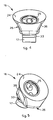
fig. 4 is a medial lateral view of a part of the humeral prosthesis infig. 1 ; -
fig. 5 is a perspective view of the part infig. 3 ; -
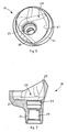
fig. 6 is a perspective view of another part of the humeral prosthesis infig. 1 ; -
fig. 7 is a front section of the part infig. 6 ; -
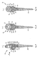
fig. 8 is a front section of the humeral prosthesis infig. 1 ; -
fig. 9 is a first medial lateral section of the humeral prosthesis infig. 1 in the direction indicated by the arrow G infig. 8 ; -
fig. 10 is a second medial lateral section of the humeral prosthesis infig. 1 in the direction indicated by the arrow G infig. 8 ; -
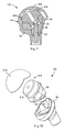
fig. 11 is a front section of a variant of the prosthesis infig. 1 ; and -
fig. 12 is a perspective view in separate parts of a variant of the prosthesis infig. 1 . - With reference to
fig. 1 , an inversehumeral prosthesis 10 comprises anarticulation device 15 which is able to articulate with acorresponding glenosphere 12 made of polyethylene, fixed in the glenoid cavity, and to be fixed to the meta-epiphysary part of the humerus. - In the following description we shall refer mainly to an inverse prosthesis, but without excluding the application to an anatomical or normal prosthesis.
- The
articulation device 15 comprises aninsert 16, made of polyethylene, pivoted around a pivoting axis Y to ahumeral body 18, made of a cobalt-based alloy. - The
device 15 also typically contains a connectingshaft 20 made of a titanium-based alloy, coaxial with the axis Y and fixed to the lower part of thehumeral body 18. In particular, theshaft 20 has anend 19 with a determinate taper, for conical coupling with thehumeral body 18. - In a known manner, the
shaft 20 is able to be connected to the meta-epiphysary part of the humerus, so as to connect thearticulation device 15 with the humerus. - The axis Y thus represents the axis around which the movements of intra-rotation and extra-rotation of the humerus take place.
- A
rotation pin 22 is provided which functions as a rotation guide between theinsert 16 and thehumeral body 18, so that the whole is aligned with the axis Y, and which prevents the deformation of the polyethylene which makes up theinsert 16. Thepin 22 is able to be screwed into aseating 23 made on theend 19 of theshaft 20. - The
insert 16 and thehumeral body 18 have reciprocally complementary or congruent shapes, so as to be able to be coupled rotationally. - The
insert 16 and thehumeral body 18 are represented individually respectively infigs. 4 and 5 and infigs. 6 and 7 . - In the solution shown, both the
insert 16 and thehumeral body 18 have the shape of a flared cup, one of a size slightly different from the other, which develop around the axis Y. - In particular, the
humeral body 18 haslateral walls 38 which delimit internally aconcave seating 28 to locate theinsert 16. Thewalls 38 are suitably shaped so as to have a curvilinear development around the axis Y and so as to be, axially, substantially vertical or slightly inclined and flared. - The
humeral body 18 is provided at the lower part with aprotuberance 31, in which a longitudinal throughcavity 29 is made. In the throughcavity 29 the conical coupling with theend 19 of theshaft 20 occurs. - The particular solution shown of the
humeral body 18 is a cup cut transversely along an inclined plane as can be seen infig. 7 , and with a barrier element, or containingedge 21, which has the function of at least partly covering the polyethylene and prevent or reduce the filling by fibrous tissue of the cavities and interstices of thedevice 15, once theprosthesis 10 has been implanted. - The
insert 16, on an upper side, has a concave seating, orhumeral seating 24, in which anarticulation platelet 14 is housed and fixed (figs. 3 ,8 and 9 ), made of an alloy based on cobalt, or titanium or ceramic, which during the normal use of theprosthesis 10 is interposed between theinsert 16 and theglenosphere 12. - The
platelet 14 mainly functions as an articulation interface between thedevice 15 and theglenosphere 12. - In particular, the
platelet 14 has a concave external surface 39 (figs. 3 ,8, 9 and 10 ) suitably shaped, for articulation with theglenosphere 12. - At the lower part, the
platelet 14 hascylindrical pins 35, with a stabilizing function under load, inserted freely or with interference into the holes of theinsert 16, to prevent accidental dis-assembly. - The presence of the
platelet 14 is advantageous since, being made of metal, it determines a metal-plastic contact which allows the correct articulation of thepolyethylene glenosphere 12 which otherwise would have to articulate on theinsert 16, also made of polyethylene, with dangerous results for the articulation itself. - Advantageously, therefore, the
platelet 14 is made of a material suitable for articulation with theglenosphere 12. - The
platelet 14 also has the function, known for example from the patent application UD2004A000194 in the name of the present Applicant, of preventing or at least limiting the phenomenon of scapular notch, thanks to the anti-wear properties of the material of which it is made. - At the bottom, on the contrary, the
insert 16 has aconvex portion 26, suitable to be inserted rotatably into theconcave seating 28 of thehumeral body 18. - The
convex portion 26 has alateral surface 36, shaped so as to have a curvilinear development around the axis Y, coherent with the shaping of thewalls 38 of theseating 28 and, on the side opposite theseating 24, has aprotuberance 17 which is inserted into the throughcavity 29 of thehumeral body 18. - The
protuberance 17 has anannular attachment tooth 33 able to cooperate with acorresponding attachment portion 34 of thecavity 29, to achieve a snap-in attachment and prevent an unwanted axial uncoupling of theinsert 16 and thehumeral body 18. - The
protuberance 17 of theconvex portion 26 has a throughhole 25, through which saidrotation pin 22 is inserted. - Once the
humeral body 18 is coupled conically with theshaft 20, thepin 22 is inserted into the throughcavity 29 and screwed into theseating 23 of theshaft 20. Thepin 22 thus abuts axially with anabutment portion 32, on the bottom of theseating 28. - Subsequently, the
insert 16 is housed rotatably in theseating 28 of thehumeral body 18, taking care that thepin 22 also passes through thehole 25 made along theprotuberance 17 of theinsert 16. Above, thepin 22 does not interfere in rotation with theinsert 16 or with theplatelet 14. Therefore, theshaft 20, thepin 22 and thehumeral body 18 are solidly associated with each other and are rotatable around the axis Y, with respect to theinsert 16, in movements of intra-rotation and extra-rotation, as indicated by the arrow R infigs. 1 and 2 . - In the solution shown, the rotation of the
insert 16 and thehumeral body 18 is limited to a determinateangular sector 27. - To this purpose, the
lateral surface 36 and thewalls 38 are suitably shaped in a complementary manner with respect to each other. - In particular, the
lateral surface 36 of theinsert 16 is axially flared, in a manner congruent with thewalls 38 of thehumeral body 18, with a slightly variable thickness or cross section. - In a variant, the
surface 36 is substantially vertical with a constant section. - In the solution shown, the development in cross section, that is, around the axis Y, of the
surface 36 and thewalls 38 is substantially defined by two convergent segments, which can be rectilinear, concave or convex according to needs, and connected by a central curvilinear segment, as can be seen infigs. 5 and6 . - Both the
surfaces 36 and thewalls 38 are suitably beveled and joined, so as not to cause points of discontinuity or steps, which could impede the fluidity and naturalness of rotation. - According to the invention, when the
humeral body 18 is driven rotationally, in the movements of intra-rotation and extra-rotation, thewalls 38 abut on thecorresponding surface 36 of theinsert 16, limiting the rotation. - The
surface 36 of theinsert 16 thus constitutes an abutment portion and an impediment to the further rotation of thehumeral body 18. - As can be seen from
fig. 6 , and fromfigs. 9 and 10 , which show sections relating to two parallel and offset planes, the section or thickness of thewalls 38 is variable, increasing from the center towards the periphery, following the greater transverse inclination of thehumeral body 18. - In this way, a geometry of the
seating 28 is defined which delimits the determinateangular sector 27, as can be seen infig. 6 . - The coupling of the
protuberance 17 of theinsert 16 and thehole 29 of thehumeral body 18, and hence thepin 22, and the relative pivoting axis Y, are thus more displaced towards the periphery of thehumeral body 18 with the larger inclination, making available for rotation the surface of theangular sector 27 towards the periphery of thehumeral body 18 with lesser inclination. - The
humeral body 18 is thus free to rotate, in a clockwise or anti-clockwise direction, in this determinateangular sector 27 which, in this case, has an amplitude of about 60°, that is, between +30° and -30°. - With a rotation of the humerus beyond the determinate
angular sector 27, thewalls 38 abut on themating surface 36 and a further rotation in said direction causes the rotation, as a single body, of thehumeral body 18 together with theinsert 16, with therelative platelet 14. - Therefore, in cases of intra-rotation and extra-rotation of the humerus greater than about 30°, the traditional articulation of the
articulation device 15 occurs with respect to theglenosphere 12. -
Figs. 11 and 12 show as a variant the application of the present invention to a normal oranatomical prosthesis 110, in which the same reference numbers are used for parts equal to those of the solution shown infigs. 1 to 10 . Theprosthesis 110, unlike theprosthesis 10, provides that an artificial concave glenoid seating made of polyethylene, not shown here, is mounted on the glenoid cavity, whereas thearticulation device 15 shown above is mounted on the humerus, in which, however, instead of thearticulation platelet 14 anarticulation member 114 is provided, at least partly convex. - The
member 114 is formed by an at least partlyspherical head 214, of shape and size coherent with the artificial glenoid seating for articulation therewith, and by asupport element 314 by means of which thehead 214 is connected to theinsert 16. Thesupport element 314 is coupled with theinsert 16 substantially in the same way as theplatelet 14 and theinsert 16 are coupled, as already described. On the contrary, thesupport element 314 is connected to thehead 214 by conical coupling of a conical part thereof with amating cavity 414 of thehead 214. - At least the
head 214 is preferably made of cobalt-based alloy, for an effective articulation with the artificial glenoid seating. - Advantageously, the prosthesis according to the present invention can be configured both as an
inverse prosthesis 10 and also as anormal prosthesis 110, simply by changing thearticulation platelet 14 with thearticulation member 114. - It is clear that modifications and/or additions of parts may be made to the
humeral prosthesis - For example, the
platelet 14, thearticulation member 114 and thehumeral body 18 can be made, at least partly, of a metal alloy based on titanium subjected to surface treatments of hardening, such as nitriding. - It is also clear that, although the present invention has been described with reference to some specific examples, a person of skill in the articulation shall certainly be able to achieve many other equivalent forms of humeral prosthesis, having the characteristics as set forth in the claims and hence all coming within the field of protection defined thereby.
Claims (15)
- Humeral prosthesis for the articulation of a humerus in a scapula of a shoulder having a glenoid cavity, comprising an articulation device, an articulation element (12) and attachment means (20), the articulation element (15) being (15) able to be associated both with the articulation element (12) mounted on the glenoid cavity, and also at the top of said humerus by means of the attachment means (20), wherein the articulation device (15) comprises an insert (16) made of polyethylene based material and able to articulate with the articulation element (12), further comprising a humeral body (18) associated with said attachment means (20), characterized in that the insert (16) and the humeral body (18) are pivotable to each other around a pivoting axis (Y) to allow a free but limited movement of intra-rotation and extra-rotation thereof around the pivoting axis (Y).
- Prosthesis as in claim 1, wherein the articulation device (15) comprises a first limiting element (36) and a second limiting element (38) which are able to cooperate with each other in order to define an angular sector (27) that limits the reciprocal rotation of the insert (16) and the humeral body (18).
- Prosthesis as in claim 1, wherein the insert (16) comprises a convex portion (26) and the humeral body (18) comprises a concave portion (28) in which the convex portion (26) of the insert (16) is able to be rotatably accommodated.
- Prosthesis as in claim 3, wherein the convex portion (26) of the insert (16) has a curvilinear shaped surface and the concave portion (28) of the humeral body (18) has a wall shaped in a manner at least partly mating with the curvilinear shaped wall.
- Prosthesis as in claims 2 and 4, wherein the first limiting element comprises the curvilinear shaped surface (36) and the second limiting element comprises the wall (38).
- Prosthesis as in claim 2, wherein the angular sector (27) has an amplitude comprised between about 30° and 90°, advantageously between 50° and 70°.
- Prosthesis as in any claim from 4 to 6, wherein the curvilinear shaped surface (36) and the wall (38) are axially inclined and flared.
- Prosthesis as in any claim from 4 to 6, wherein the curvilinear shaped surface (36) and the wall (38) are substantially vertical.
- Prosthesis as in any claim hereinbefore, wherein it comprises pivoting means (22) to pivot the insert (16) to the humeral body (18).
- Prosthesis as in any claim hereinbefore, wherein the articulation element (12) is at least partly convex and the insert (16) is at least partly concave.
- Prosthesis as in any claim hereinbefore, wherein the articulation device (15) comprises an articulation platelet (14) mounted on the first element (16) and able to be disposed during use between the insert (16) and the articulation element (12), the articulation platelet (14) having a concave shape for articulation with the articulation element (12).
- Prosthesis as in any claim from 1 to 9, wherein the articulation element (12) is at least partly concave and the insert (16) is at least partly convex and wherein the articulation device (15) comprises an articulation member (114) disposed during use between the insert (16) and the articulation element (12), which is formed by an articulation head (214), convex in shape, for the articulation of the articulation element (12) and mounted on a support element (314), in turn mounted on the insert (16).
- Prosthesis as in claim 11, wherein the articulation platelet (14) is made of a different material from the material of which the insert (16) is made.
- Prosthesis as in claim 12, wherein the support element (314) is made of a different material from the material of which the articulation element (12) is made.
- Prosthesis as in any claim hereinbefore, wherein the attachment means consists of a shaft (20) fixed to the humeral body (18) and which is able to be connected to the humerus.
Applications Claiming Priority (2)
| Application Number | Priority Date | Filing Date | Title |
|---|---|---|---|
| IT000122A ITUD20070122A1 (en) | 2007-07-03 | 2007-07-03 | HOMERAL PROSTHESIS |
| PCT/IB2008/001744 WO2009004469A1 (en) | 2007-07-03 | 2008-07-02 | Humeral prosthesis |
Publications (2)
| Publication Number | Publication Date |
|---|---|
| EP2175807A1 EP2175807A1 (en) | 2010-04-21 |
| EP2175807B1 true EP2175807B1 (en) | 2013-01-16 |
Family
ID=38863437
Family Applications (1)
| Application Number | Title | Priority Date | Filing Date |
|---|---|---|---|
| EP08776320A Active EP2175807B1 (en) | 2007-07-03 | 2008-07-02 | Humeral prosthesis |
Country Status (5)
| Country | Link |
|---|---|
| US (1) | US8343226B2 (en) |
| EP (1) | EP2175807B1 (en) |
| AU (1) | AU2008272605B2 (en) |
| IT (1) | ITUD20070122A1 (en) |
| WO (1) | WO2009004469A1 (en) |
Families Citing this family (16)
| Publication number | Priority date | Publication date | Assignee | Title |
|---|---|---|---|---|
| KR101146215B1 (en) | 2004-02-04 | 2012-05-11 | 엘디알 메디칼 | Intervertebral disc prosthesis |
| FR2891135B1 (en) | 2005-09-23 | 2008-09-12 | Ldr Medical Sarl | INTERVERTEBRAL DISC PROSTHESIS |
| NZ594917A (en) * | 2009-03-11 | 2014-02-28 | Exactech Inc | Motion inducing reverse shoulder assembly |
| US9421106B2 (en) | 2011-12-07 | 2016-08-23 | Howmedica Osteonics Corp. | Reverse shoulder baseplate with alignment guide for glenosphere |
| US8906102B2 (en) * | 2012-05-31 | 2014-12-09 | Howmedica Osteonics Corp. | Lateral entry insert for cup trial |
| US8663334B2 (en) * | 2012-05-31 | 2014-03-04 | Howmedica Osteonics Corp. | Lateral entry insert for cup trial |
| WO2015051471A1 (en) * | 2013-10-13 | 2015-04-16 | Startech Engineering Ag | Joint implant |
| EP2873392B1 (en) * | 2013-11-14 | 2016-03-30 | Arthrex, Inc. | Shoulder implant with stem |
| US20150342743A1 (en) * | 2014-05-28 | 2015-12-03 | Kareem Sobky | Shoulder endoprosthesis |
| US20160296336A1 (en) | 2015-04-07 | 2016-10-13 | Gerhard E. Maale | Torsionally Stabilized Endoprosthetic Device |
| US9861493B2 (en) | 2015-08-14 | 2018-01-09 | Gerhard E. Maale | Glenoid fossa prosthesis |
| US10485670B2 (en) | 2015-08-14 | 2019-11-26 | Gerhard E. Maale | Glenoid fossa prosthesis |
| US10390972B2 (en) | 2016-01-15 | 2019-08-27 | Howmedica Osteonics Corp. | Humeral trial adaptor |
| GB201601159D0 (en) * | 2016-01-21 | 2016-03-09 | Univ Hospitals Coventry & Warwickshire Nhs Trust | Prosthesis |
| US11419680B2 (en) | 2016-10-07 | 2022-08-23 | New York Society For The Relief Of The Ruptured And Crippled, Maintaining The Hospital For Special Surgery | Patient specific 3-D interactive total joint model and surgical planning system |
| KR102788656B1 (en) * | 2017-06-29 | 2025-03-28 | 앙코르 메디컬, 엘.피.(디/비/에이 디제이오 서지컬) | Glenosphere with inserts for augmented fixation and related methods |
Family Cites Families (8)
| Publication number | Priority date | Publication date | Assignee | Title |
|---|---|---|---|---|
| FR2652498B1 (en) | 1989-10-04 | 1997-12-26 | Medinov | MODULAR ASSEMBLY FOR SHOULDER PROSTHESIS. |
| FR2841768B1 (en) * | 2002-07-05 | 2005-05-06 | Tornier Sa | SHOULDER OR HIP PROSTHESIS FACILITATING ABDUCTION |
| US7011686B2 (en) * | 2002-09-30 | 2006-03-14 | Depuy Products, Inc. | Reverse-type humeral prosthesis |
| GB0320287D0 (en) | 2003-08-29 | 2003-10-01 | Stanmore Implants Worldwide | Shoulder joint prosthetic system |
| FR2863865B1 (en) * | 2003-12-19 | 2006-10-06 | Tornier Sa | SHOULDER OR HIP PROSTHESIS AND METHOD OF MOUNTING |
| FR2872025B1 (en) | 2004-06-28 | 2006-08-25 | Tornier Sas | PROSTHESIS OF SHOULDER OR HIP |
| ITUD20040194A1 (en) | 2004-10-19 | 2005-01-19 | Lima Lto Spa | REVERSE PROSTHESIS FOR THE ARTICULATION OF THE SHOULDER |
| FR2900045B1 (en) | 2006-04-21 | 2009-01-16 | Tornier Sas | PROSTHESIS OF SHOULDER OR HIP |
-
2007
- 2007-07-03 IT IT000122A patent/ITUD20070122A1/en unknown
-
2008
- 2008-07-02 US US12/666,567 patent/US8343226B2/en active Active
- 2008-07-02 AU AU2008272605A patent/AU2008272605B2/en not_active Ceased
- 2008-07-02 WO PCT/IB2008/001744 patent/WO2009004469A1/en not_active Ceased
- 2008-07-02 EP EP08776320A patent/EP2175807B1/en active Active
Also Published As
| Publication number | Publication date |
|---|---|
| US20100211178A1 (en) | 2010-08-19 |
| ITUD20070122A1 (en) | 2009-01-04 |
| WO2009004469A1 (en) | 2009-01-08 |
| AU2008272605A2 (en) | 2010-03-25 |
| EP2175807A1 (en) | 2010-04-21 |
| US8343226B2 (en) | 2013-01-01 |
| AU2008272605B2 (en) | 2013-12-19 |
| AU2008272605A1 (en) | 2009-01-08 |
Similar Documents
| Publication | Publication Date | Title |
|---|---|---|
| US8343226B2 (en) | Humeral prosthesis | |
| US11464643B2 (en) | Shoulder arthroplasty systems and configurations for components thereof | |
| CA1070452A (en) | Trispherical prosthetic shoulder device | |
| CN106456334B (en) | Knee Endoprosthesis | |
| KR101340861B1 (en) | Humeral component of a shoulder joint prosthesis | |
| CA1115454A (en) | Prosthetic joint | |
| JP6434037B2 (en) | Joint implant | |
| JP2011528236A (en) | Total replacement artificial knee joint with higher-order NURBS curved surface | |
| EP3838231A1 (en) | Component for a joint replacement | |
| EP3104813B1 (en) | Artificial knee joint | |
| US20260102255A1 (en) | Reverse shoulder prosthesis and related methods | |
| EP3332749B1 (en) | Shoulder prosthesis comprising a glenohumeral component | |
| US20250017737A1 (en) | Reverse shoulder prosthesis and related methods | |
| JP4356842B2 (en) | Knee prosthesis | |
| KR20260072595A (en) | Reverse shoulder prosthesis and related methods | |
| WO2025059049A1 (en) | Reverse shoulder prosthesis and related methods |
Legal Events
| Date | Code | Title | Description |
|---|---|---|---|
| PUAI | Public reference made under article 153(3) epc to a published international application that has entered the european phase |
Free format text: ORIGINAL CODE: 0009012 |
|
| 17P | Request for examination filed |
Effective date: 20100202 |
|
| AK | Designated contracting states |
Kind code of ref document: A1 Designated state(s): AT BE BG CH CY CZ DE DK EE ES FI FR GB GR HR HU IE IS IT LI LT LU LV MC MT NL NO PL PT RO SE SI SK TR |
|
| AX | Request for extension of the european patent |
Extension state: AL BA MK RS |
|
| DAX | Request for extension of the european patent (deleted) | ||
| GRAP | Despatch of communication of intention to grant a patent |
Free format text: ORIGINAL CODE: EPIDOSNIGR1 |
|
| RAP1 | Party data changed (applicant data changed or rights of an application transferred) |
Owner name: LIMACORPORATE S.P.A. |
|
| GRAS | Grant fee paid |
Free format text: ORIGINAL CODE: EPIDOSNIGR3 |
|
| GRAA | (expected) grant |
Free format text: ORIGINAL CODE: 0009210 |
|
| AK | Designated contracting states |
Kind code of ref document: B1 Designated state(s): AT BE BG CH CY CZ DE DK EE ES FI FR GB GR HR HU IE IS IT LI LT LU LV MC MT NL NO PL PT RO SE SI SK TR |
|
| REG | Reference to a national code |
Ref country code: GB Ref legal event code: FG4D |
|
| REG | Reference to a national code |
Ref country code: CH Ref legal event code: EP |
|
| REG | Reference to a national code |
Ref country code: IE Ref legal event code: FG4D |
|
| REG | Reference to a national code |
Ref country code: AT Ref legal event code: REF Ref document number: 593452 Country of ref document: AT Kind code of ref document: T Effective date: 20130215 Ref country code: CH Ref legal event code: EP |
|
| REG | Reference to a national code |
Ref country code: DE Ref legal event code: R096 Ref document number: 602008021726 Country of ref document: DE Effective date: 20130314 |
|
| REG | Reference to a national code |
Ref country code: CH Ref legal event code: NV Representative=s name: DS-PAT, DANIEL STONA, CH |
|
| REG | Reference to a national code |
Ref country code: AT Ref legal event code: MK05 Ref document number: 593452 Country of ref document: AT Kind code of ref document: T Effective date: 20130116 |
|
| REG | Reference to a national code |
Ref country code: NL Ref legal event code: VDEP Effective date: 20130116 |
|
| REG | Reference to a national code |
Ref country code: LT Ref legal event code: MG4D |
|
| PG25 | Lapsed in a contracting state [announced via postgrant information from national office to epo] |
Ref country code: SE Free format text: LAPSE BECAUSE OF FAILURE TO SUBMIT A TRANSLATION OF THE DESCRIPTION OR TO PAY THE FEE WITHIN THE PRESCRIBED TIME-LIMIT Effective date: 20130116 Ref country code: NO Free format text: LAPSE BECAUSE OF FAILURE TO SUBMIT A TRANSLATION OF THE DESCRIPTION OR TO PAY THE FEE WITHIN THE PRESCRIBED TIME-LIMIT Effective date: 20130416 Ref country code: AT Free format text: LAPSE BECAUSE OF FAILURE TO SUBMIT A TRANSLATION OF THE DESCRIPTION OR TO PAY THE FEE WITHIN THE PRESCRIBED TIME-LIMIT Effective date: 20130116 Ref country code: IS Free format text: LAPSE BECAUSE OF FAILURE TO SUBMIT A TRANSLATION OF THE DESCRIPTION OR TO PAY THE FEE WITHIN THE PRESCRIBED TIME-LIMIT Effective date: 20130516 Ref country code: ES Free format text: LAPSE BECAUSE OF FAILURE TO SUBMIT A TRANSLATION OF THE DESCRIPTION OR TO PAY THE FEE WITHIN THE PRESCRIBED TIME-LIMIT Effective date: 20130427 Ref country code: BE Free format text: LAPSE BECAUSE OF FAILURE TO SUBMIT A TRANSLATION OF THE DESCRIPTION OR TO PAY THE FEE WITHIN THE PRESCRIBED TIME-LIMIT Effective date: 20130116 Ref country code: BG Free format text: LAPSE BECAUSE OF FAILURE TO SUBMIT A TRANSLATION OF THE DESCRIPTION OR TO PAY THE FEE WITHIN THE PRESCRIBED TIME-LIMIT Effective date: 20130416 Ref country code: LT Free format text: LAPSE BECAUSE OF FAILURE TO SUBMIT A TRANSLATION OF THE DESCRIPTION OR TO PAY THE FEE WITHIN THE PRESCRIBED TIME-LIMIT Effective date: 20130116 |
|
| PG25 | Lapsed in a contracting state [announced via postgrant information from national office to epo] |
Ref country code: PL Free format text: LAPSE BECAUSE OF FAILURE TO SUBMIT A TRANSLATION OF THE DESCRIPTION OR TO PAY THE FEE WITHIN THE PRESCRIBED TIME-LIMIT Effective date: 20130116 Ref country code: GR Free format text: LAPSE BECAUSE OF FAILURE TO SUBMIT A TRANSLATION OF THE DESCRIPTION OR TO PAY THE FEE WITHIN THE PRESCRIBED TIME-LIMIT Effective date: 20130417 Ref country code: SI Free format text: LAPSE BECAUSE OF FAILURE TO SUBMIT A TRANSLATION OF THE DESCRIPTION OR TO PAY THE FEE WITHIN THE PRESCRIBED TIME-LIMIT Effective date: 20130116 Ref country code: FI Free format text: LAPSE BECAUSE OF FAILURE TO SUBMIT A TRANSLATION OF THE DESCRIPTION OR TO PAY THE FEE WITHIN THE PRESCRIBED TIME-LIMIT Effective date: 20130116 Ref country code: LV Free format text: LAPSE BECAUSE OF FAILURE TO SUBMIT A TRANSLATION OF THE DESCRIPTION OR TO PAY THE FEE WITHIN THE PRESCRIBED TIME-LIMIT Effective date: 20130116 Ref country code: PT Free format text: LAPSE BECAUSE OF FAILURE TO SUBMIT A TRANSLATION OF THE DESCRIPTION OR TO PAY THE FEE WITHIN THE PRESCRIBED TIME-LIMIT Effective date: 20130516 Ref country code: NL Free format text: LAPSE BECAUSE OF FAILURE TO SUBMIT A TRANSLATION OF THE DESCRIPTION OR TO PAY THE FEE WITHIN THE PRESCRIBED TIME-LIMIT Effective date: 20130116 |
|
| PG25 | Lapsed in a contracting state [announced via postgrant information from national office to epo] |
Ref country code: HR Free format text: LAPSE BECAUSE OF FAILURE TO SUBMIT A TRANSLATION OF THE DESCRIPTION OR TO PAY THE FEE WITHIN THE PRESCRIBED TIME-LIMIT Effective date: 20130116 |
|
| PG25 | Lapsed in a contracting state [announced via postgrant information from national office to epo] |
Ref country code: EE Free format text: LAPSE BECAUSE OF FAILURE TO SUBMIT A TRANSLATION OF THE DESCRIPTION OR TO PAY THE FEE WITHIN THE PRESCRIBED TIME-LIMIT Effective date: 20130116 Ref country code: SK Free format text: LAPSE BECAUSE OF FAILURE TO SUBMIT A TRANSLATION OF THE DESCRIPTION OR TO PAY THE FEE WITHIN THE PRESCRIBED TIME-LIMIT Effective date: 20130116 Ref country code: RO Free format text: LAPSE BECAUSE OF FAILURE TO SUBMIT A TRANSLATION OF THE DESCRIPTION OR TO PAY THE FEE WITHIN THE PRESCRIBED TIME-LIMIT Effective date: 20130116 Ref country code: DK Free format text: LAPSE BECAUSE OF FAILURE TO SUBMIT A TRANSLATION OF THE DESCRIPTION OR TO PAY THE FEE WITHIN THE PRESCRIBED TIME-LIMIT Effective date: 20130116 Ref country code: CZ Free format text: LAPSE BECAUSE OF FAILURE TO SUBMIT A TRANSLATION OF THE DESCRIPTION OR TO PAY THE FEE WITHIN THE PRESCRIBED TIME-LIMIT Effective date: 20130116 |
|
| PLBE | No opposition filed within time limit |
Free format text: ORIGINAL CODE: 0009261 |
|
| STAA | Information on the status of an ep patent application or granted ep patent |
Free format text: STATUS: NO OPPOSITION FILED WITHIN TIME LIMIT |
|
| PG25 | Lapsed in a contracting state [announced via postgrant information from national office to epo] |
Ref country code: CY Free format text: LAPSE BECAUSE OF FAILURE TO SUBMIT A TRANSLATION OF THE DESCRIPTION OR TO PAY THE FEE WITHIN THE PRESCRIBED TIME-LIMIT Effective date: 20130116 |
|
| 26N | No opposition filed |
Effective date: 20131017 |
|
| REG | Reference to a national code |
Ref country code: DE Ref legal event code: R097 Ref document number: 602008021726 Country of ref document: DE Effective date: 20131017 |
|
| PG25 | Lapsed in a contracting state [announced via postgrant information from national office to epo] |
Ref country code: MC Free format text: LAPSE BECAUSE OF FAILURE TO SUBMIT A TRANSLATION OF THE DESCRIPTION OR TO PAY THE FEE WITHIN THE PRESCRIBED TIME-LIMIT Effective date: 20130116 |
|
| REG | Reference to a national code |
Ref country code: IE Ref legal event code: MM4A |
|
| PG25 | Lapsed in a contracting state [announced via postgrant information from national office to epo] |
Ref country code: IE Free format text: LAPSE BECAUSE OF NON-PAYMENT OF DUE FEES Effective date: 20130702 |
|
| PG25 | Lapsed in a contracting state [announced via postgrant information from national office to epo] |
Ref country code: TR Free format text: LAPSE BECAUSE OF FAILURE TO SUBMIT A TRANSLATION OF THE DESCRIPTION OR TO PAY THE FEE WITHIN THE PRESCRIBED TIME-LIMIT Effective date: 20130116 Ref country code: MT Free format text: LAPSE BECAUSE OF FAILURE TO SUBMIT A TRANSLATION OF THE DESCRIPTION OR TO PAY THE FEE WITHIN THE PRESCRIBED TIME-LIMIT Effective date: 20130116 |
|
| PG25 | Lapsed in a contracting state [announced via postgrant information from national office to epo] |
Ref country code: LU Free format text: LAPSE BECAUSE OF NON-PAYMENT OF DUE FEES Effective date: 20130702 Ref country code: HU Free format text: LAPSE BECAUSE OF FAILURE TO SUBMIT A TRANSLATION OF THE DESCRIPTION OR TO PAY THE FEE WITHIN THE PRESCRIBED TIME-LIMIT; INVALID AB INITIO Effective date: 20080702 |
|
| REG | Reference to a national code |
Ref country code: FR Ref legal event code: PLFP Year of fee payment: 9 |
|
| REG | Reference to a national code |
Ref country code: FR Ref legal event code: PLFP Year of fee payment: 10 |
|
| REG | Reference to a national code |
Ref country code: FR Ref legal event code: PLFP Year of fee payment: 11 |
|
| REG | Reference to a national code |
Ref country code: CH Ref legal event code: PFA Owner name: LIMACORPORATE S.P.A., IT Free format text: FORMER OWNER: LIMACORPORATE S.P.A., IT |
|
| PGFP | Annual fee paid to national office [announced via postgrant information from national office to epo] |
Ref country code: IT Payment date: 20220707 Year of fee payment: 15 Ref country code: GB Payment date: 20220711 Year of fee payment: 15 Ref country code: DE Payment date: 20220729 Year of fee payment: 15 |
|
| PGFP | Annual fee paid to national office [announced via postgrant information from national office to epo] |
Ref country code: FR Payment date: 20220708 Year of fee payment: 15 |
|
| PGFP | Annual fee paid to national office [announced via postgrant information from national office to epo] |
Ref country code: CH Payment date: 20220715 Year of fee payment: 15 |
|
| P01 | Opt-out of the competence of the unified patent court (upc) registered |
Effective date: 20230520 |
|
| REG | Reference to a national code |
Ref country code: DE Ref legal event code: R119 Ref document number: 602008021726 Country of ref document: DE |
|
| REG | Reference to a national code |
Ref country code: CH Ref legal event code: PL |
|
| GBPC | Gb: european patent ceased through non-payment of renewal fee |
Effective date: 20230702 |
|
| PG25 | Lapsed in a contracting state [announced via postgrant information from national office to epo] |
Ref country code: DE Free format text: LAPSE BECAUSE OF NON-PAYMENT OF DUE FEES Effective date: 20240201 Ref country code: CH Free format text: LAPSE BECAUSE OF NON-PAYMENT OF DUE FEES Effective date: 20230731 Ref country code: GB Free format text: LAPSE BECAUSE OF NON-PAYMENT OF DUE FEES Effective date: 20230702 |
|
| PG25 | Lapsed in a contracting state [announced via postgrant information from national office to epo] |
Ref country code: FR Free format text: LAPSE BECAUSE OF NON-PAYMENT OF DUE FEES Effective date: 20230731 |
|
| PG25 | Lapsed in a contracting state [announced via postgrant information from national office to epo] |
Ref country code: IT Free format text: LAPSE BECAUSE OF NON-PAYMENT OF DUE FEES Effective date: 20230702 |