EP2175336A1 - Adaptive Performance Model and Methods for System Maintenance - Google Patents
Adaptive Performance Model and Methods for System Maintenance Download PDFInfo
- Publication number
- EP2175336A1 EP2175336A1 EP09172062A EP09172062A EP2175336A1 EP 2175336 A1 EP2175336 A1 EP 2175336A1 EP 09172062 A EP09172062 A EP 09172062A EP 09172062 A EP09172062 A EP 09172062A EP 2175336 A1 EP2175336 A1 EP 2175336A1
- Authority
- EP
- European Patent Office
- Prior art keywords
- data
- correction value
- modeled
- measured data
- gas turbine
- Prior art date
- Legal status (The legal status is an assumption and is not a legal conclusion. Google has not performed a legal analysis and makes no representation as to the accuracy of the status listed.)
- Withdrawn
Links
- 238000000034 method Methods 0.000 title claims description 24
- 230000003044 adaptive effect Effects 0.000 title description 2
- 238000012423 maintenance Methods 0.000 title description 2
- 238000012544 monitoring process Methods 0.000 claims abstract description 19
- 238000004088 simulation Methods 0.000 claims abstract description 17
- 239000000446 fuel Substances 0.000 description 10
- 239000003570 air Substances 0.000 description 3
- 238000010586 diagram Methods 0.000 description 2
- 230000004075 alteration Effects 0.000 description 1
- 239000012080 ambient air Substances 0.000 description 1
- 230000015556 catabolic process Effects 0.000 description 1
- 238000005094 computer simulation Methods 0.000 description 1
- 238000006731 degradation reaction Methods 0.000 description 1
- 238000002347 injection Methods 0.000 description 1
- 239000007924 injection Substances 0.000 description 1
- 238000007689 inspection Methods 0.000 description 1
- 239000000203 mixture Substances 0.000 description 1
- 238000006467 substitution reaction Methods 0.000 description 1
Images
Classifications
-
- G—PHYSICS
- G05—CONTROLLING; REGULATING
- G05B—CONTROL OR REGULATING SYSTEMS IN GENERAL; FUNCTIONAL ELEMENTS OF SUCH SYSTEMS; MONITORING OR TESTING ARRANGEMENTS FOR SUCH SYSTEMS OR ELEMENTS
- G05B23/00—Testing or monitoring of control systems or parts thereof
- G05B23/02—Electric testing or monitoring
- G05B23/0205—Electric testing or monitoring by means of a monitoring system capable of detecting and responding to faults
- G05B23/0218—Electric testing or monitoring by means of a monitoring system capable of detecting and responding to faults characterised by the fault detection method dealing with either existing or incipient faults
- G05B23/0243—Electric testing or monitoring by means of a monitoring system capable of detecting and responding to faults characterised by the fault detection method dealing with either existing or incipient faults model based detection method, e.g. first-principles knowledge model
- G05B23/0254—Electric testing or monitoring by means of a monitoring system capable of detecting and responding to faults characterised by the fault detection method dealing with either existing or incipient faults model based detection method, e.g. first-principles knowledge model based on a quantitative model, e.g. mathematical relationships between inputs and outputs; functions: observer, Kalman filter, residual calculation, Neural Networks
Definitions
- the subject matter disclosed herein relates to systems and methods for monitoring the performance of gas turbine engines.
- Gas turbine engines are used, for example, as a source of power in planes, trains, ships, electrical generators, and tanks.
- Gas turbine engines typically include three main components, a compressor, a combustor, and a turbine.
- Control systems monitor conditions of the gas turbine engine and control one or more actuators of the components to achieve a desired power output.
- the performance of one or more of the components may degrade. For example, flow capacities and other operating conditions may vary from the original assumed conditions. Because of the degradation, the control of the gas turbine engine becomes increasingly out of tune. This may cause the gas turbine engine to operate at states that diverge from desired operational states. In some cases, the operation of the gas turbine engine at less than desirable operational states can cause durability concerns regarding its components.
- a system includes a correction factor module that receives modeled data generated from a simulation model and measured data, that determines a difference between the modeled data and the measured data, and that applies a filter to the difference to determine a correction value; and a performance monitoring module that analyzes the correction value, and that generates a component alert based on the analysis.
- a system for monitoring the performance of a gas turbine engine includes a correction factor module that receives modeled data generated from a real-time gas turbine engine simulation model and measured data sensed from the gas turbine engine in real-time, that determines a difference between the modeled data and the measured data, and that applies a filter to the difference to determine a correction value; and a performance monitoring module that analyzes the correction value, and that generates a component alert based on the analysis.
- a method for monitoring the performance of a gas turbine engine includes: receiving measured data sensed from the gas turbine engine in real-time; determining a difference between the measured data and modeled data generated from a real-time gas turbine engine simulation model; applying a filter to the difference to determine a correction value; performing an analysis of the correction value; and generating a component alert based on the analysis.
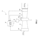
- a gas turbine engine system 10 that includes a real-time component performance monitoring system in accordance with an exemplary embodiment.
- the gas turbine engine system 10 includes a compressor 12, a combustor 14, and a turbine 16.
- the turbine 16 is coupled to the compressor 12 via a compressor shaft (not shown).
- the combustor 14 is disposed between the compressor 12 and the turbine 16.
- Ambient air is drawn into the compressor 12 and compressed therein.
- the compressed air is supplied to the combustor 14.
- a fuel injection system 18 supplies fuel to the compressed air within the combustor 14.
- the air/fuel mixture is combusted within the combustor 14 to increase the energy content of the compressed gas.
- the high-energy gas passes over a first set of blades of the turbine 16, causing the turbine 16 to spin.
- the turbine spin mechanically powers the compressor 12 via the compressor shaft.
- the resulting high-pressure, high-velocity exhaust gas passes through a nozzle (not shown), thereby generating thrust by accelerating the hot exhaust, by expansion, back to atmospheric pressure.
- the resulting exhaust gas passes over a second set of turbine blades (not shown), thereby causing an output shaft (not shown) coupled to the turbine 16 to spin.
- the output shaft is coupled to a generator (not shown). The generator converts the mechanical energy of the output shaft to electrical energy.
- the operation of the exemplary gas turbine engine system 10 is monitored by one or more sensors 30a-30n.
- the sensors 30a-30n detect and measure various observable conditions of the gas turbine engine system 10, the generator, and/or the ambient environment.
- the sensors 30a-30n include, temperature sensors, pressures sensors, humidity sensors, fuel flow sensors, speed sensors, flame detector sensors, valve position sensors, guide vane angle sensors, or the like that measure the various parameters at various locations in the gas turbine engine system 10.
- One or more redundant sensors 31 similarly detect and measure various observable conditions of the gas turbine engine system 10.
- a control module 32 receives the signals generated by the one or more sensors 30a-30n. Based on the signals, the control module 32 controls one or more components of the gas turbine engine system 10. The control module 32 further monitors the real-time performance of the components to determine a current status of the components in accordance with the present disclosure.
- the control module 32 includes one or more sub-modules and datastores.
- module and sub-module refer to an application specific integrated circuit (ASIC), an electronic circuit, a processor (shared, dedicated, or group) and memory that executes one or more software or firmware programs, a combinational logic circuit, and/or other suitable components that provide the described functionality.
- ASIC application specific integrated circuit
- processor shared, dedicated, or group
- memory that executes one or more software or firmware programs, a combinational logic circuit, and/or other suitable components that provide the described functionality.
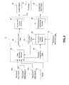
- control module 32 includes a data modeling module 34, a correction factor module 36, a performance monitoring module 38, and a component control module 40.
- the data modeling module 34 receives as input one or more measured data signals 40a-40n that are generated by the one or more sensors 30a-30n ( FIG. 1 ) of the gas turbine engine system 10 ( FIG. 1 ), and a predefined simulation model 42. Based on the measured data signals, the data modeling module 34 performs operations of the predefined simulation model 42.
- the simulation model 42 can be, for example, a physics-based aero-thermodynamic computer model, a regression-fit model, a neural-net model, and/or other suitable models for simulating one or more features of the gas turbine engine system 10 ( FIG. 1 ). Based on the execution of the operations of the predefined simulation model 42, the data modeling module 34 generates modeled comparison data 44 and modeled control data 46 that correspond to the gas turbine engine system 10 ( FIG. 1 ).
- the model 42 includes a simulation of the gas turbine engine system 10 ( FIG. 1 ).
- the measured data signals 40a-40n include, ambient conditions, an angle of inlet guide vanes, an amount of fuel, and a rotational speed of the turbine.
- the data modeling module 34 executes the operations of the turbine model 42 based on these measured data signals 40a-40n and generates the modeled comparison data 44 and the modeled control data 46.
- the modeled comparison data 44 can include a modeled power output, a modeled turbine exhaust temperature, and/or a modeled compressor condition.
- the modeled control data 46 can include desired values, for example, a desired fuel flow rate.
- the component control module 40 receives as input the modeled control data 46 and, optionally, other measured data signals (inputs not shown). Based on the inputs, the component control module 40 controls the operation of one or more component of the gas turbine engine system 10 ( FIG. 1 ) via a control signal 48 and/or generates a prediction 50 of the operation of one or more component.
- the component control module 40 receives as input a desired fuel rate and controls an actual fuel flow rate of the fuel system 18 ( FIG. 1 ) to the combustor 12 ( FIG. 1 ) to be at or near the desired fuel flow rate.
- the correction factor module 36 receives as input the modeled comparison data 44 and a measured data signal 52 relating to the modeled comparison data 44.
- the measured data signal 52 is a redundant measured signal generated by one of the redundant sensors 31.
- the correction factor module 36 normalizes the modeled comparison data 44 and the data of the measured data signal 52 and compares the normalized modeled comparison data to the normalized measured data to determine a difference.
- the correction factor module 36 then applies a filter to the difference to determine a correction factor 54.
- the filter is a Kalman filter.
- the correction factor 54 includes a data match multiplier (DMM) that has a value of 1.0 when the difference is zero or near zero (e.g., less than a predetermined value). As the performance of the related component degrades and the difference increases (or decrease), the value of the DMM adjusts to be less than or greater than 1.0.
- DMM data match multiplier
- the simulation model 42 is a real-time adaptive model that includes adjustable parameters.
- the adjustable parameters can be automatically adjusted in real-time to adapt the model 42 to meet varying conditions.
- the data modeling module 34 further receives as input the correction factor 54.
- the data modeling module 34 adjusts the adjustable parameters based on the correction factor 54 to conform the simulation model 42 to the degraded component.
- the performance monitoring module 38 receives as input the correction factor 54.
- the performance monitoring module 38 tracks the changes in the correction factor 54 for the respective component.
- the performance monitoring module 38 By analyzing the changes or the correction factor 54 directly, the performance monitoring module 38 generates a component alert signal 56.
- the performance monitoring module 38 analyzes the changes or the correction factor 54 by at least one of: performing a comparison of the correction factor 54 with a pre-determined condition; performing a comparison of the correction factor 54 or changes with a historical correction value of the gas turbine engine system 10; and comparing a rate-of-change of the correction value to a pre-determined threshold.
- the component alert signal 56 sets a status of a predefined diagnostic code relating to the component.
- the component alert signal 56 includes the diagnostic code.
- the diagnostic code can then be retrieved by a service tool directly or wirelessly connected to the control module 32 ( FIG.1 ) and/or transmitted to a remote location, for example, via a telematics system.
- the component alert signal 56 illuminates an indicator lamp indicating the alert status of the component.
- the component alert signal 56 includes an audio warning signal that activates an audio device that, when sounded, indicates the alert status of the component.
- the component alert signal 56 can be accessible to a technician, and/or an operator of the gas turbine engine system 10 ( FIG. 1 ). Based on the component alert signal 56, the technician and/or operator can: determine and schedule maintenance of the component; perform an inspection of the component for foreign objects, foreign object damage, or other hardware failures before a next operation; or cease operation of the gas turbine engine prior to the occurrence of damage to the component.
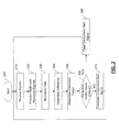
- FIG. 3 a flowchart illustrates a component performance monitoring method that can be performed by the control module 32 of FIG. 2 in accordance with an exemplary embodiment.
- the order of operation within the method is not limited to the sequential execution as illustrated in FIG. 3 , but may be performed in one or more varying orders as applicable and in accordance with the present disclosure.
- one or more steps of the method can be added or deleted from the method shown in FIG. 3 without altering the spirit of the method.
- the method is scheduled to run based on predetermined events, and/or at a selected time. In various other embodiments, the method is scheduled to run continually during the operation of the gas turbine engine system 10 ( FIG. 1 ).
- the method may begin at 200.
- the measured data signals 40a-40n are received at 210.
- the operations of the model 42 are performed and the modeled comparison data 44 is generated at 220.
- the modeled comparison data 44 and the corresponding redundant measured data 52 are normalized at 230.
- the normalized data values are compared to determine a difference at 240.
- a filter is applied to the difference (as discussed earlier) at 250 to determine the correction factor 54.
- the correction factor 54 is evaluated at 260. If the correction factor 54 does not meet predetermined criteria (e.g., not within a predetermined range, not equal to a predetermined value, greater than or less than a predetermined value, etc.) at 260, then the component alert signal 56 is generated at 270 and the method continues at 210 by receiving the measured inputs. Otherwise, if the correction factor 54 does meet the predetermined criteria at 260, the component alert signal 56 is cleared at 280 and the method continues at 210 by receiving the measured inputs.
- predetermined criteria e.g., not within a predetermined range, not equal to a predetermined value, greater than or less than a predetermined value, etc.
- the method can be applied to each component of the gas turbine engine system 10 ( FIG. 1 ), and/or to sub-components of the components of the gas turbine engine system 10 ( FIG. 1 ) individually, or collectively.
Landscapes
- Physics & Mathematics (AREA)
- Engineering & Computer Science (AREA)
- Artificial Intelligence (AREA)
- Evolutionary Computation (AREA)
- Mathematical Physics (AREA)
- General Physics & Mathematics (AREA)
- Automation & Control Theory (AREA)
- Testing And Monitoring For Control Systems (AREA)
Abstract
A system includes a correction factor module (36) that receives modeled data (44) generated from a simulation model (42) and measured data (52), that determines a difference between the modeled data (44) and the measured data (52), and that applies a filter to the difference to determine a correction value (54); and a performance monitoring module (38) that analyzes the correction value, and that generates a component alert (56) based on the analysis.
Description
- The subject matter disclosed herein relates to systems and methods for monitoring the performance of gas turbine engines.
- Gas turbine engines are used, for example, as a source of power in planes, trains, ships, electrical generators, and tanks. Gas turbine engines typically include three main components, a compressor, a combustor, and a turbine. Control systems monitor conditions of the gas turbine engine and control one or more actuators of the components to achieve a desired power output.
- As the gas turbine engine operates over an extended period of time, the performance of one or more of the components may degrade. For example, flow capacities and other operating conditions may vary from the original assumed conditions. Because of the degradation, the control of the gas turbine engine becomes increasingly out of tune. This may cause the gas turbine engine to operate at states that diverge from desired operational states. In some cases, the operation of the gas turbine engine at less than desirable operational states can cause durability concerns regarding its components.
- According to one aspect of the invention, a system includes a correction factor module that receives modeled data generated from a simulation model and measured data, that determines a difference between the modeled data and the measured data, and that applies a filter to the difference to determine a correction value; and a performance monitoring module that analyzes the correction value, and that generates a component alert based on the analysis.
- According to a second aspect of the invention, a system for monitoring the performance of a gas turbine engine is provided. The system includes a correction factor module that receives modeled data generated from a real-time gas turbine engine simulation model and measured data sensed from the gas turbine engine in real-time, that determines a difference between the modeled data and the measured data, and that applies a filter to the difference to determine a correction value; and a performance monitoring module that analyzes the correction value, and that generates a component alert based on the analysis.
- According to a third aspect of the invention, a method for monitoring the performance of a gas turbine engine is provided. The method includes: receiving measured data sensed from the gas turbine engine in real-time; determining a difference between the measured data and modeled data generated from a real-time gas turbine engine simulation model; applying a filter to the difference to determine a correction value; performing an analysis of the correction value; and generating a component alert based on the analysis.
- These and other advantages and features will become more apparent from the following description taken in conjunction with the drawings.
- There follows a detailed description of embodiments of the invention by way of example only with reference to the accompanying drawings, in which:
-
FIG. 1 is a functional block diagram illustrating a gas turbine engine system that includes a component performance monitoring system in accordance with an exemplary embodiment; -
FIG. 2 is a dataflow diagram illustrating a control module of the gas turbine engine system ofFIG. 1 in accordance with an exemplary embodiment; and -
FIG. 3 is a flowchart illustrating a component performance monitoring method that can be performed by the control module ofFIG. 2 in accordance with an exemplary embodiment. - Referring to
FIG. 1 , a gasturbine engine system 10 is provided that includes a real-time component performance monitoring system in accordance with an exemplary embodiment. In various embodiments, the gasturbine engine system 10 includes acompressor 12, acombustor 14, and aturbine 16. Theturbine 16 is coupled to thecompressor 12 via a compressor shaft (not shown). Thecombustor 14 is disposed between thecompressor 12 and theturbine 16. - Ambient air is drawn into the
compressor 12 and compressed therein. The compressed air is supplied to thecombustor 14. A fuel injection system 18 supplies fuel to the compressed air within thecombustor 14. The air/fuel mixture is combusted within thecombustor 14 to increase the energy content of the compressed gas. The high-energy gas passes over a first set of blades of theturbine 16, causing theturbine 16 to spin. The turbine spin mechanically powers thecompressor 12 via the compressor shaft. - In various embodiments, the resulting high-pressure, high-velocity exhaust gas passes through a nozzle (not shown), thereby generating thrust by accelerating the hot exhaust, by expansion, back to atmospheric pressure. In various other embodiments, the resulting exhaust gas passes over a second set of turbine blades (not shown), thereby causing an output shaft (not shown) coupled to the
turbine 16 to spin. In various embodiments, the output shaft is coupled to a generator (not shown). The generator converts the mechanical energy of the output shaft to electrical energy. - The operation of the exemplary gas
turbine engine system 10 is monitored by one ormore sensors 30a-30n. Thesensors 30a-30n detect and measure various observable conditions of the gasturbine engine system 10, the generator, and/or the ambient environment. In one example, thesensors 30a-30n include, temperature sensors, pressures sensors, humidity sensors, fuel flow sensors, speed sensors, flame detector sensors, valve position sensors, guide vane angle sensors, or the like that measure the various parameters at various locations in the gasturbine engine system 10. One or moreredundant sensors 31 similarly detect and measure various observable conditions of the gasturbine engine system 10. - A
control module 32 receives the signals generated by the one ormore sensors 30a-30n. Based on the signals, thecontrol module 32 controls one or more components of the gasturbine engine system 10. Thecontrol module 32 further monitors the real-time performance of the components to determine a current status of the components in accordance with the present disclosure. - Turning now to
FIG. 2 , thecontrol module 32 is shown in more detail in accordance with an exemplary embodiment. Thecontrol module 32 includes one or more sub-modules and datastores. As used herein the terms module and sub-module refer to an application specific integrated circuit (ASIC), an electronic circuit, a processor (shared, dedicated, or group) and memory that executes one or more software or firmware programs, a combinational logic circuit, and/or other suitable components that provide the described functionality. - As can be appreciated, the sub-modules shown in
FIG. 2 can be combined and/or further partitioned to similarly control the gas turbine engine system 10 (FIG. 1 ) and/or to monitor the performance of the gas turbine engine system 10 (FIG. 1 ). In this example, thecontrol module 32 includes adata modeling module 34, acorrection factor module 36, aperformance monitoring module 38, and acomponent control module 40. - The
data modeling module 34 receives as input one or more measureddata signals 40a-40n that are generated by the one ormore sensors 30a-30n (FIG. 1 ) of the gas turbine engine system 10 (FIG. 1 ), and apredefined simulation model 42. Based on the measured data signals, thedata modeling module 34 performs operations of thepredefined simulation model 42. Thesimulation model 42 can be, for example, a physics-based aero-thermodynamic computer model, a regression-fit model, a neural-net model, and/or other suitable models for simulating one or more features of the gas turbine engine system 10 (FIG. 1 ). Based on the execution of the operations of thepredefined simulation model 42, thedata modeling module 34 generates modeledcomparison data 44 and modeledcontrol data 46 that correspond to the gas turbine engine system 10 (FIG. 1 ). - In one example, the
model 42 includes a simulation of the gas turbine engine system 10 (FIG. 1 ). In this example, the measureddata signals 40a-40n include, ambient conditions, an angle of inlet guide vanes, an amount of fuel, and a rotational speed of the turbine. Thedata modeling module 34 executes the operations of theturbine model 42 based on these measureddata signals 40a-40n and generates the modeledcomparison data 44 and the modeledcontrol data 46. In this example, the modeledcomparison data 44 can include a modeled power output, a modeled turbine exhaust temperature, and/or a modeled compressor condition. The modeledcontrol data 46 can include desired values, for example, a desired fuel flow rate. - The
component control module 40 receives as input the modeledcontrol data 46 and, optionally, other measured data signals (inputs not shown). Based on the inputs, thecomponent control module 40 controls the operation of one or more component of the gas turbine engine system 10 (FIG. 1 ) via acontrol signal 48 and/or generates aprediction 50 of the operation of one or more component. - In one example, the
component control module 40 receives as input a desired fuel rate and controls an actual fuel flow rate of the fuel system 18 (FIG. 1 ) to the combustor 12 (FIG. 1 ) to be at or near the desired fuel flow rate. - The
correction factor module 36 receives as input the modeledcomparison data 44 and a measureddata signal 52 relating to the modeledcomparison data 44. In one example, the measureddata signal 52 is a redundant measured signal generated by one of theredundant sensors 31. - The
correction factor module 36 normalizes the modeledcomparison data 44 and the data of the measureddata signal 52 and compares the normalized modeled comparison data to the normalized measured data to determine a difference. Thecorrection factor module 36 then applies a filter to the difference to determine acorrection factor 54. In one example the filter is a Kalman filter. - In various embodiments, the
correction factor 54 includes a data match multiplier (DMM) that has a value of 1.0 when the difference is zero or near zero (e.g., less than a predetermined value). As the performance of the related component degrades and the difference increases (or decrease), the value of the DMM adjusts to be less than or greater than 1.0. - In various embodiments, the
simulation model 42 is a real-time adaptive model that includes adjustable parameters. The adjustable parameters can be automatically adjusted in real-time to adapt themodel 42 to meet varying conditions. In this case, thedata modeling module 34 further receives as input thecorrection factor 54. Thedata modeling module 34 adjusts the adjustable parameters based on thecorrection factor 54 to conform thesimulation model 42 to the degraded component. - The
performance monitoring module 38 receives as input thecorrection factor 54. Theperformance monitoring module 38 tracks the changes in thecorrection factor 54 for the respective component. By analyzing the changes or thecorrection factor 54 directly, theperformance monitoring module 38 generates acomponent alert signal 56. In one example, theperformance monitoring module 38 analyzes the changes or thecorrection factor 54 by at least one of: performing a comparison of thecorrection factor 54 with a pre-determined condition; performing a comparison of thecorrection factor 54 or changes with a historical correction value of the gasturbine engine system 10; and comparing a rate-of-change of the correction value to a pre-determined threshold. - In various embodiments, the
component alert signal 56 sets a status of a predefined diagnostic code relating to the component. In various embodiments, thecomponent alert signal 56 includes the diagnostic code. The diagnostic code can then be retrieved by a service tool directly or wirelessly connected to the control module 32 (FIG.1 ) and/or transmitted to a remote location, for example, via a telematics system. In various other embodiments, thecomponent alert signal 56 illuminates an indicator lamp indicating the alert status of the component. In various other embodiments, thecomponent alert signal 56 includes an audio warning signal that activates an audio device that, when sounded, indicates the alert status of the component. - As can be appreciated, the
component alert signal 56 can be accessible to a technician, and/or an operator of the gas turbine engine system 10 (FIG. 1 ). Based on thecomponent alert signal 56, the technician and/or operator can: determine and schedule maintenance of the component; perform an inspection of the component for foreign objects, foreign object damage, or other hardware failures before a next operation; or cease operation of the gas turbine engine prior to the occurrence of damage to the component. - Turning now to
FIG. 3 and with continued reference toFIG. 2 , a flowchart illustrates a component performance monitoring method that can be performed by thecontrol module 32 ofFIG. 2 in accordance with an exemplary embodiment. As can be appreciated in light of the disclosure, the order of operation within the method is not limited to the sequential execution as illustrated inFIG. 3 , but may be performed in one or more varying orders as applicable and in accordance with the present disclosure. As can be appreciated, one or more steps of the method can be added or deleted from the method shown inFIG. 3 without altering the spirit of the method. - In various embodiments, the method is scheduled to run based on predetermined events, and/or at a selected time. In various other embodiments, the method is scheduled to run continually during the operation of the gas turbine engine system 10 (
FIG. 1 ). - In one example, the method may begin at 200. The measured data signals 40a-40n are received at 210. Based on the measured data signals 40a-40n, the operations of the
model 42 are performed and the modeledcomparison data 44 is generated at 220. The modeledcomparison data 44 and the corresponding redundant measureddata 52 are normalized at 230. The normalized data values are compared to determine a difference at 240. A filter is applied to the difference (as discussed earlier) at 250 to determine thecorrection factor 54. - The
correction factor 54 is evaluated at 260. If thecorrection factor 54 does not meet predetermined criteria (e.g., not within a predetermined range, not equal to a predetermined value, greater than or less than a predetermined value, etc.) at 260, then thecomponent alert signal 56 is generated at 270 and the method continues at 210 by receiving the measured inputs. Otherwise, if thecorrection factor 54 does meet the predetermined criteria at 260, thecomponent alert signal 56 is cleared at 280 and the method continues at 210 by receiving the measured inputs. - As can be appreciated, the method can be applied to each component of the gas turbine engine system 10 (
FIG. 1 ), and/or to sub-components of the components of the gas turbine engine system 10 (FIG. 1 ) individually, or collectively. - While the invention has been described in detail in connection with only a limited number of embodiments, it should be readily understood that the invention is not limited to such disclosed embodiments. Rather, the invention can be modified to incorporate any number of variations, alterations, substitutions or equivalent arrangements not heretofore described, but which are commensurate with the spirit and scope of the invention. Additionally, while various embodiments of the invention have been described, it is to be understood that aspects of the invention may include only some of the described embodiments. Accordingly, the invention is not to be seen as limited by the foregoing description, but is only limited by the scope of the appended claims.
Claims (15)
- A system, comprising:a correction factor module (36) that receives modeled data (44) generated from a simulation model (42) and measured data (52), that determines a difference between the modeled data (44) and the measured data (52), and that applies a filter to the difference to determine a correction value (54); anda performance monitoring module (38) that analyzes the correction value (54), and that generates a component alert (56) based on the analysis.
- The system of claim 1, further comprising a data modeling module (34) that receives other measured data (40a-40n), and that generates the modeled data (44) based on the other measured data (40a-40n) and the simulation model (42).
- The system of claim 2, wherein the data modeling module (34) further generates modeled control data (46) based on the simulation model (42).
- The system of any of the preceding claims, wherein the correction factor module (54) normalizes at least one of the modeled data (44) and the measured data (52) and wherein the difference between the modeled data (44) and the measured data (52) is determined based on the normalized at least one of modeled data (44) and measured data (52).
- The system of any of the preceding claims, wherein the analysis of the correction value (54) includes at least one of a comparison to one or more pre-determined conditions and a comparison to a historical correction value.
- The system of claim 5 wherein the comparison to the historical correction value includes comparing a rate-of-change of the correction value to a pre-determined threshold.
- A system for monitoring the performance of a gas turbine engine (10), the system comprising:a correction factor module (36) that receives modeled data (44) generated from a real-time gas turbine engine simulation model (42) and measured data (52) sensed from the gas turbine engine (10) in real-time, that determines a difference between the modeled data (44) and the measured data (52), and that applies a filter to the difference to determine a correction value (54); anda performance monitoring module (38) that analyzes the correction value (54), and that generates a component alert (56) based on the analysis.
- The system of claim 7 further comprising a data modeling module (34) that receives other measured data (40a-40n) sensed from the gas turbine engine (10) in real-time, and that generates the modeled data (44) a based on the simulation model (42) and the other measured data (40a-40n).
- A method for monitoring the performance of a gas turbine engine, the method comprising:receiving measured data sensed from the gas turbine engine in real-time;determining a difference between the measured data and modeled data generated from a real-time gas turbine engine simulation model;applying a filter to the difference to determine a correction value;performing an analysis of the correction value; andgenerating a component alert based on the analysis.
- The method of claim 9, further comprising generating modeled control data based on a predefined model and measured data.
- The method of claim 10, further comprising controlling at least one of a component and a sub-component of the gas turbine engine based on the modeled control data.
- The method of any of claims 9 to 11, further comprising normalizing at least one of the modeled data and the measured data and wherein the determining the difference between the modeled data and the measured data is based on the normalized at least one of modeled data and measured data.
- The method of any of claims 9 to 12, wherein performing the analysis of the correction value includes performing a comparison of the correction value with a pre-determined condition.
- The method of any of claims 9 to 12, wherein the performing the analysis of the correction value includes performing a comparison of the correction value to with a historical correction value of the gas turbine engine.
- The method of claim 14, wherein the performing the comparison of the correction value with the historical correction value includes comparing a rate-of-change of the correction value to a pre-determined threshold.
Applications Claiming Priority (1)
| Application Number | Priority Date | Filing Date | Title |
|---|---|---|---|
| US12/249,176 US20100089067A1 (en) | 2008-10-10 | 2008-10-10 | Adaptive performance model and methods for system maintenance |
Publications (1)
| Publication Number | Publication Date |
|---|---|
| EP2175336A1 true EP2175336A1 (en) | 2010-04-14 |
Family
ID=41395102
Family Applications (1)
| Application Number | Title | Priority Date | Filing Date |
|---|---|---|---|
| EP09172062A Withdrawn EP2175336A1 (en) | 2008-10-10 | 2009-10-02 | Adaptive Performance Model and Methods for System Maintenance |
Country Status (4)
| Country | Link |
|---|---|
| US (1) | US20100089067A1 (en) |
| EP (1) | EP2175336A1 (en) |
| JP (1) | JP2010090896A (en) |
| CN (1) | CN101726416A (en) |
Cited By (12)
| Publication number | Priority date | Publication date | Assignee | Title |
|---|---|---|---|---|
| WO2011134708A1 (en) * | 2010-04-28 | 2011-11-03 | Siemens Aktiengesellschaft | Method for the thermodynamic online diagnosis of a large industrial plant |
| EP2388672A1 (en) * | 2010-05-18 | 2011-11-23 | United Technologies Corporation | Identifying of turbomachine faults |
| WO2011160943A1 (en) * | 2010-06-21 | 2011-12-29 | Optimized Systems And Solutions Limited | Asset health monitoring using stable distributions for heavy-tailed data |
| EP2570880A3 (en) * | 2011-09-19 | 2013-09-11 | The Boeing Company | A method for real-time model based structural anomaly detection |
| EP2562611A3 (en) * | 2011-08-23 | 2013-11-13 | General Electric Company | Process for adaptive modeling of performance degradation |
| EP2762852A1 (en) * | 2013-02-05 | 2014-08-06 | Siemens Aktiengesellschaft | Automatic Testing System for a Gas Turbine |
| FR3036798A1 (en) * | 2015-06-01 | 2016-12-02 | Turbomeca | METHOD FOR DETECTING A MECHANICAL FAULT OF A GAS GENERATOR OF A TURBOMACHINE OF AN AIRCRAFT AND CORRESPONDING IMPLEMENTATION DEVICE |
| WO2017140286A1 (en) * | 2016-02-17 | 2017-08-24 | MTU Aero Engines AG | Method for determining the influence of an inner test stand on a gas turbine operated in the inner test stand |
| EP2570616A3 (en) * | 2011-09-15 | 2017-10-04 | General Electric Company | System and method for simulating a gas turbine compressor |
| CN110262381A (en) * | 2019-07-06 | 2019-09-20 | 精华电子(苏州)有限公司 | A kind of industrial control unit (ICU) |
| EP3719721A1 (en) * | 2019-04-05 | 2020-10-07 | United Technologies Corporation | Aircraft component repair scheduling system and process |
| CN112987700A (en) * | 2021-04-27 | 2021-06-18 | 湖南中车时代通信信号有限公司 | Integrated test system of magnetic suspension traffic operation control system |
Families Citing this family (21)
| Publication number | Priority date | Publication date | Assignee | Title |
|---|---|---|---|---|
| US8290631B2 (en) * | 2009-03-12 | 2012-10-16 | Emerson Process Management Power & Water Solutions, Inc. | Methods and apparatus to arbitrate valve position sensor redundancy |
| JP5634907B2 (en) | 2011-02-10 | 2014-12-03 | 株式会社日立製作所 | Compressor control device and control method |
| US20120283963A1 (en) * | 2011-05-05 | 2012-11-08 | Mitchell David J | Method for predicting a remaining useful life of an engine and components thereof |
| JP5845705B2 (en) * | 2011-08-11 | 2016-01-20 | 株式会社Ihi | Gas turbine performance estimation device |
| US8710976B2 (en) * | 2012-01-13 | 2014-04-29 | General Electric Company | Automated incorporation of expert feedback into a monitoring system |
| FR2993375B1 (en) * | 2012-07-10 | 2014-07-18 | Snecma | METHOD FOR DETECTING A DEGRADATION OF A TURBOMACHINE BY MONITORING THE PERFORMANCE OF THE TURBOMACHINE |
| US9255525B2 (en) * | 2012-11-30 | 2016-02-09 | General Electric Company | System and method for gas turbine operation |
| JP6604939B2 (en) | 2013-03-15 | 2019-11-13 | ユナイテッド テクノロジーズ コーポレイション | Control system, control method and gas turbine engine |
| US9605559B2 (en) | 2015-02-02 | 2017-03-28 | General Electric Company | Wash timing based on turbine operating parameters |
| JP6522445B2 (en) | 2015-06-30 | 2019-05-29 | 三菱日立パワーシステムズ株式会社 | Control parameter optimization system and operation control optimization apparatus having the same |
| US9897013B2 (en) | 2015-09-02 | 2018-02-20 | General Electric Company | Systems and methods for determining gas turbine operating space |
| EP3206093A1 (en) * | 2016-02-09 | 2017-08-16 | Siemens Aktiengesellschaft | Detection of temperature sensor failure in turbine systems |
| US20170307460A1 (en) * | 2016-04-25 | 2017-10-26 | Pratt & Whitney Canada Corp. | Correction of pressure measurements in engines |
| US10401881B2 (en) * | 2017-02-14 | 2019-09-03 | General Electric Company | Systems and methods for quantification of a gas turbine inlet filter blockage |
| WO2019173702A1 (en) * | 2018-03-08 | 2019-09-12 | Public Utility District No. 1 of Chelan County, WA | Machine modeling system and method |
| US11755791B2 (en) * | 2018-07-03 | 2023-09-12 | Rtx Corporation | Aircraft component qualification system and process |
| CN109458563A (en) * | 2018-10-23 | 2019-03-12 | 青岛理工大学 | Dynamic self-adaptive simulation modeling method for open local water supply pipe network |
| CN110080886B (en) * | 2019-04-16 | 2020-09-04 | 新奥能源动力科技(上海)有限公司 | Method and device for controlling fuel pressurization system |
| US11149654B2 (en) | 2020-03-04 | 2021-10-19 | General Electric Company | Systems, program products, and methods for adjusting operating limit (OL) threshold for compressors of gas turbine systems based on mass flow loss |
| US12117823B1 (en) * | 2020-06-10 | 2024-10-15 | United Services Automobile Association (Usaa) | Monitoring systems and methods for assessing risk |
| CN115492691B (en) * | 2022-09-07 | 2025-08-29 | 中国联合重型燃气轮机技术有限公司 | Gas turbine control method, device and system |
Citations (2)
| Publication number | Priority date | Publication date | Assignee | Title |
|---|---|---|---|---|
| GB2363211A (en) * | 2000-06-08 | 2001-12-12 | Fisher Rosemount Systems Inc | Adaptive predictive model for a process control system |
| EP1204076A2 (en) * | 2000-11-02 | 2002-05-08 | General Electric Company | Methods and apparatus for monitoring gas turbine engine operation |
Family Cites Families (9)
| Publication number | Priority date | Publication date | Assignee | Title |
|---|---|---|---|---|
| US3731070A (en) * | 1971-04-27 | 1973-05-01 | United Aircraft Corp | Gas turbine engine analyzer |
| US4208550A (en) * | 1978-03-03 | 1980-06-17 | General Electric Company | Magnetic parallel-to-serial converter for gas turbine engine parameter sensor |
| US4249238A (en) * | 1978-05-24 | 1981-02-03 | The United States Of America As Represented By The Administrator Of The National Aeronautics And Space Administration | Apparatus for sensor failure detection and correction in a gas turbine engine control system |
| US4215412A (en) * | 1978-07-13 | 1980-07-29 | The Boeing Company | Real time performance monitoring of gas turbine engines |
| US6343251B1 (en) * | 2000-10-20 | 2002-01-29 | General Electric Company | Method and system for monitoring the operation of and predicting part life consumption for turbomachinery |
| US6823675B2 (en) * | 2002-11-13 | 2004-11-30 | General Electric Company | Adaptive model-based control systems and methods for controlling a gas turbine |
| FR2849387B1 (en) * | 2002-12-26 | 2005-02-25 | Ela Medical Sa | ACTIVE IMPLANTABLE MEDICAL DEVICE SUCH AS A CARDIAC STIMULATOR, DEFIBRILLATOR, CARDIOVERTER OR MULTISITE DEVICE, DETECTION OF POST-STIMULATING EVOLVING POTENTIALS, IN PARTICULAR AURICULAR |
| US6962043B2 (en) * | 2003-01-30 | 2005-11-08 | General Electric Company | Method and apparatus for monitoring the performance of a gas turbine system |
| US7742904B2 (en) * | 2005-09-27 | 2010-06-22 | General Electric Company | Method and system for gas turbine engine simulation using adaptive Kalman filter |
-
2008
- 2008-10-10 US US12/249,176 patent/US20100089067A1/en not_active Abandoned
-
2009
- 2009-10-02 EP EP09172062A patent/EP2175336A1/en not_active Withdrawn
- 2009-10-07 JP JP2009232926A patent/JP2010090896A/en not_active Withdrawn
- 2009-10-10 CN CN200910206868A patent/CN101726416A/en active Pending
Patent Citations (2)
| Publication number | Priority date | Publication date | Assignee | Title |
|---|---|---|---|---|
| GB2363211A (en) * | 2000-06-08 | 2001-12-12 | Fisher Rosemount Systems Inc | Adaptive predictive model for a process control system |
| EP1204076A2 (en) * | 2000-11-02 | 2002-05-08 | General Electric Company | Methods and apparatus for monitoring gas turbine engine operation |
Cited By (21)
| Publication number | Priority date | Publication date | Assignee | Title |
|---|---|---|---|---|
| WO2011134708A1 (en) * | 2010-04-28 | 2011-11-03 | Siemens Aktiengesellschaft | Method for the thermodynamic online diagnosis of a large industrial plant |
| EP2388672A1 (en) * | 2010-05-18 | 2011-11-23 | United Technologies Corporation | Identifying of turbomachine faults |
| US8862433B2 (en) | 2010-05-18 | 2014-10-14 | United Technologies Corporation | Partitioning of turbomachine faults |
| WO2011160943A1 (en) * | 2010-06-21 | 2011-12-29 | Optimized Systems And Solutions Limited | Asset health monitoring using stable distributions for heavy-tailed data |
| EP2562611A3 (en) * | 2011-08-23 | 2013-11-13 | General Electric Company | Process for adaptive modeling of performance degradation |
| EP2570616A3 (en) * | 2011-09-15 | 2017-10-04 | General Electric Company | System and method for simulating a gas turbine compressor |
| US9020689B2 (en) | 2011-09-19 | 2015-04-28 | The Boeing Company | Method for real-time model based structural anomaly detection |
| EP2570880A3 (en) * | 2011-09-19 | 2013-09-11 | The Boeing Company | A method for real-time model based structural anomaly detection |
| EP2762852A1 (en) * | 2013-02-05 | 2014-08-06 | Siemens Aktiengesellschaft | Automatic Testing System for a Gas Turbine |
| JP2016513202A (en) * | 2013-02-05 | 2016-05-12 | シーメンス アクチエンゲゼルシヤフトSiemens Aktiengesellschaft | Automatic test system for gas turbine |
| RU2627617C2 (en) * | 2013-02-05 | 2017-08-09 | Сименс Акциенгезелльшафт | Automatic testing system for gas turbine |
| KR20170109087A (en) * | 2013-02-05 | 2017-09-27 | 지멘스 악티엔게젤샤프트 | Auto testing system for a gas turbine |
| WO2014122013A1 (en) | 2013-02-05 | 2014-08-14 | Siemens Aktiengesellschaft | Auto testing system for a gas turbine |
| US10067035B2 (en) | 2013-02-05 | 2018-09-04 | Siemens Aktiengesellschaft | Auto testing system for a gas turbine |
| FR3036798A1 (en) * | 2015-06-01 | 2016-12-02 | Turbomeca | METHOD FOR DETECTING A MECHANICAL FAULT OF A GAS GENERATOR OF A TURBOMACHINE OF AN AIRCRAFT AND CORRESPONDING IMPLEMENTATION DEVICE |
| WO2016193603A1 (en) * | 2015-06-01 | 2016-12-08 | Safran Helicopter Engines | Method for detecting a mechanical defect in an aircraft turbine engine gas generator, and corresponding device for implementing said method |
| WO2017140286A1 (en) * | 2016-02-17 | 2017-08-24 | MTU Aero Engines AG | Method for determining the influence of an inner test stand on a gas turbine operated in the inner test stand |
| EP3719721A1 (en) * | 2019-04-05 | 2020-10-07 | United Technologies Corporation | Aircraft component repair scheduling system and process |
| US11447271B2 (en) | 2019-04-05 | 2022-09-20 | Raytheon Technologies Corporation | Aircraft component repair scheduling system and process |
| CN110262381A (en) * | 2019-07-06 | 2019-09-20 | 精华电子(苏州)有限公司 | A kind of industrial control unit (ICU) |
| CN112987700A (en) * | 2021-04-27 | 2021-06-18 | 湖南中车时代通信信号有限公司 | Integrated test system of magnetic suspension traffic operation control system |
Also Published As
| Publication number | Publication date |
|---|---|
| JP2010090896A (en) | 2010-04-22 |
| US20100089067A1 (en) | 2010-04-15 |
| CN101726416A (en) | 2010-06-09 |
Similar Documents
| Publication | Publication Date | Title |
|---|---|---|
| EP2175336A1 (en) | Adaptive Performance Model and Methods for System Maintenance | |
| US6892127B2 (en) | Methods and apparatus for assessing gas turbine engine damage | |
| US6868325B2 (en) | Transient fault detection system and method using Hidden Markov Models | |
| US7742904B2 (en) | Method and system for gas turbine engine simulation using adaptive Kalman filter | |
| EP1452936B1 (en) | Method for detecting an impending sensor failure | |
| US7603222B2 (en) | Sensor diagnostics using embedded model quality parameters | |
| US9317249B2 (en) | Operations support systems and methods for calculating and evaluating turbine temperatures and health | |
| US9091616B2 (en) | Engine operations support systems and methods for reducing fuel flow | |
| EP3757356A1 (en) | Control of power generation system by visually monitoring gauge during operation | |
| EP3757696A1 (en) | Control of power generation system by visually monitoring valve during operation | |
| JP2022022126A (en) | Control on power generating system under online maintenance using multiple maintenance modes | |
| EP3757357A1 (en) | Control of power generation system by visually monitoring component during operation | |
| US12252995B2 (en) | Acoustical health monitoring of gas turbine engines | |
| Palmé et al. | Similarity based modeling for turbine exit temperature spread monitoring on gas turbines | |
| Goebel | Decision forgetting and decision smoothing for diagnostic decision fusion in systems with redundant information | |
| Borguet et al. | Assessment of an anomaly detector for jet engine health monitoring | |
| Xia | Engine health monitoring based on remote diagnostics |
Legal Events
| Date | Code | Title | Description |
|---|---|---|---|
| PUAI | Public reference made under article 153(3) epc to a published international application that has entered the european phase |
Free format text: ORIGINAL CODE: 0009012 |
|
| AK | Designated contracting states |
Kind code of ref document: A1 Designated state(s): AT BE BG CH CY CZ DE DK EE ES FI FR GB GR HR HU IE IS IT LI LT LU LV MC MK MT NL NO PL PT RO SE SI SK SM TR |
|
| 17P | Request for examination filed |
Effective date: 20101014 |
|
| 17Q | First examination report despatched |
Effective date: 20101109 |
|
| STAA | Information on the status of an ep patent application or granted ep patent |
Free format text: STATUS: THE APPLICATION IS DEEMED TO BE WITHDRAWN |
|
| 18D | Application deemed to be withdrawn |
Effective date: 20130503 |