EP2175297A2 - Methods and apparatus for automation of the testing and measurement of optical fiber - Google Patents
Methods and apparatus for automation of the testing and measurement of optical fiber Download PDFInfo
- Publication number
- EP2175297A2 EP2175297A2 EP08161753A EP08161753A EP2175297A2 EP 2175297 A2 EP2175297 A2 EP 2175297A2 EP 08161753 A EP08161753 A EP 08161753A EP 08161753 A EP08161753 A EP 08161753A EP 2175297 A2 EP2175297 A2 EP 2175297A2
- Authority
- EP
- European Patent Office
- Prior art keywords
- optical fiber
- spool
- pallet
- fiber
- holding
- Prior art date
- Legal status (The legal status is an assumption and is not a legal conclusion. Google has not performed a legal analysis and makes no representation as to the accuracy of the status listed.)
- Withdrawn
Links
Images







Classifications
-
- G—PHYSICS
- G01—MEASURING; TESTING
- G01M—TESTING STATIC OR DYNAMIC BALANCE OF MACHINES OR STRUCTURES; TESTING OF STRUCTURES OR APPARATUS, NOT OTHERWISE PROVIDED FOR
- G01M11/00—Testing of optical apparatus; Testing structures by optical methods not otherwise provided for
-
- B—PERFORMING OPERATIONS; TRANSPORTING
- B65—CONVEYING; PACKING; STORING; HANDLING THIN OR FILAMENTARY MATERIAL
- B65H—HANDLING THIN OR FILAMENTARY MATERIAL, e.g. SHEETS, WEBS, CABLES
- B65H75/00—Storing webs, tapes, or filamentary material, e.g. on reels
- B65H75/02—Cores, formers, supports, or holders for coiled, wound, or folded material, e.g. reels, spindles, bobbins, cop tubes, cans, mandrels or chucks
- B65H75/18—Constructional details
- B65H75/182—Identification means
-
- B—PERFORMING OPERATIONS; TRANSPORTING
- B65—CONVEYING; PACKING; STORING; HANDLING THIN OR FILAMENTARY MATERIAL
- B65H—HANDLING THIN OR FILAMENTARY MATERIAL, e.g. SHEETS, WEBS, CABLES
- B65H49/00—Unwinding or paying-out filamentary material; Supporting, storing or transporting packages from which filamentary material is to be withdrawn or paid-out
- B65H49/18—Methods or apparatus in which packages rotate
- B65H49/20—Package-supporting devices
-
- B—PERFORMING OPERATIONS; TRANSPORTING
- B65—CONVEYING; PACKING; STORING; HANDLING THIN OR FILAMENTARY MATERIAL
- B65H—HANDLING THIN OR FILAMENTARY MATERIAL, e.g. SHEETS, WEBS, CABLES
- B65H49/00—Unwinding or paying-out filamentary material; Supporting, storing or transporting packages from which filamentary material is to be withdrawn or paid-out
- B65H49/38—Skips, cages, racks, or containers, adapted solely for the transport or storage of bobbins, cops, or the like
-
- G—PHYSICS
- G01—MEASURING; TESTING
- G01M—TESTING STATIC OR DYNAMIC BALANCE OF MACHINES OR STRUCTURES; TESTING OF STRUCTURES OR APPARATUS, NOT OTHERWISE PROVIDED FOR
- G01M11/00—Testing of optical apparatus; Testing structures by optical methods not otherwise provided for
- G01M11/30—Testing of optical devices, constituted by fibre optics or optical waveguides
-
- B—PERFORMING OPERATIONS; TRANSPORTING
- B65—CONVEYING; PACKING; STORING; HANDLING THIN OR FILAMENTARY MATERIAL
- B65H—HANDLING THIN OR FILAMENTARY MATERIAL, e.g. SHEETS, WEBS, CABLES
- B65H2701/00—Handled material; Storage means
- B65H2701/30—Handled filamentary material
- B65H2701/32—Optical fibres or optical cables
-
- G—PHYSICS
- G02—OPTICS
- G02B—OPTICAL ELEMENTS, SYSTEMS OR APPARATUS
- G02B6/00—Light guides; Structural details of arrangements comprising light guides and other optical elements, e.g. couplings
- G02B6/44—Mechanical structures for providing tensile strength and external protection for fibres, e.g. optical transmission cables
- G02B6/4439—Auxiliary devices
- G02B6/4457—Bobbins; Reels
Definitions
- the present invention relates generally to improvements in the manufacture of optical fiber. More specifically, the present invention relates to methods and apparatus for automating the testing of optical fiber wound onto a spool.
- optical fiber In the current manufacturing process for optical fiber, optical fiber is typically wound onto a spool for measurement and testing, shipping to a customer, and subsequent processing at the customer's facility.
- the measurement and testing of optical fiber is currently performed manually by multiple technicians, with carts carrying a number of spools being manually moved from test station to test station.
- a technician removes a spool from the cart and places the spool on a measurement rack.
- the technician then strips and removes the plastic fiber coating from both ends of the optical fiber, cleaning off excess coating and any remaining debris.
- the fiber ends are manipulated by the technician into a cleaver and cut.
- the technician loads the fiber ends into a computer controlled measurement system and initiates a measurement sequence to test at least one characteristic of the optical fiber, e.g., fiber cutoff wavelength, attenuation, fiber curl, cladding diameter, or coating diameter.
- the fiber is then removed from the testing system and the spool returned to the cart. All of the spools on the cart or only selected spools may be tested as desired.
- the cart is then manually moved to the next test station for another series of tests. The amount of manual labor involved results in high labor costs and higher manufacturing costs for optical fiber.
- the present invention provides advantageous methods and apparatus for the automation of the testing of optical fiber.
- the present invention includes an automated conveyor system which moves spools of optical fiber contained on pallets from testing station to testing station.
- a single spool is carried by a specially designed pallet which has a number of advantageous features described further below.
- an apparatus automatically strips, cleans, and cleaves the fiber ends once the spool reaches the apparatus. The fiber ends are then automatically manipulated into the appropriate location for a predetermined test to be performed.
- an apparatus automatically acquires a sample length of the optical fiber and strips, cleans, and cleaves the fiber ends of the sample. The sample length of the optical fiber is then manipulated into the appropriate location for a second predetermined test to be performed.
- Fig. 1 shows a top view of a spool 10 which may be advantageously used in conjunction with the present invention.
- the spool 10 comprises a primary barrel 14 and a lead meter barrel 15 separated from each other by an outboard flange 16.
- a length of optical fiber 12 has been wound onto the primary barrel 14 and the lead meter barrel 15 during the manufacturing process.
- spool 10 may be, for example, a "single" spool, having 25 km of optical fiber wound onto the primary barrel 14, or a "double” spool containing 50 km of optical fiber wound onto the primary barrel 14.
- a short length of the optical fiber 12 has been wound onto the lead meter barrel 15.
- the outboard flange 16 has a slot 17 providing a path for the optical fiber 12 between the lead meter barrel 15 and the primary barrel 14.
- an outer end 12a of the optical fiber 12 extends from the underside of the primary barrel 14 and an inner end 12b extends from the underside of the lead meter barrel 15.
- the optical fiber 12 also typically includes a plastic coating 13. Further details of a presently preferred spool 10 for use in conjunction with the present invention are provided in U.S. Patent Application Serial No. 60/115,540, filed on January 12, 1999 , entitled "System And Methods For Providing Under-Wrap Access To Optical Fiber Wound Onto Spools" which is incorporated by reference herein in its entirety.
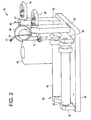
- Fig. 2 shows an isometric view of a pallet 50 in accordance with a first embodiment of the present invention.
- the pallet 50 is adapted to carry the spool 10 of optical fiber 12 such that the fiber ends 12a and 12b are available to the testing equipment of automated fiber measurement system 100 described below.
- the pallet 50 includes a roller assembly 52 mounted on a base 54 adapted for carrying the spool 10.
- the roller assembly 52 includes a pair of rollers 56 and a pair of base plates 58.
- Also mounted on the base 54 are vertical brackets 60 and 62, and an upright guide roller 64.
- a guide bar 66 is mounted to the base 54.
- a feed finger assembly 68, a pickoff assembly 70, and a clutch assembly 71 are rotationally mounted on the vertical bracket 60.
- a fiber guide 72 which includes an eyelet 74.
- a feed finger assembly 76, a guide roller 80, and a fiberguide 81 including an eyelet 83 are mounted on the vertical bracket 62.
- a center hole 84 extends through the rotational center of the feed finger assembly 68, the pickoff assembly 70, and the vertical bracket 60.
- a radio frequency (RF) identification tag 82 identifying the spool 10 is attached to the vertical bracket 60.
- the RF tag 82 is capable of storing information which has been written to it, allowing the RF tag 82 to provide a travelling database for the spool 10 as it passes through the system 100.
- the RF tag 82 provides processing instructions for individual test stations and stores the data of the test results. As each spool 10 is processed by the individual test stations of the system 100, the results of each of the tests are written to the RF tag 82. Thus, when the spool 10 has been processed by each of the appropriate test stations, the RF tag 82 contains the test results of all the tests performed. Additionally, the RF tag 82 also contains the routing instructions for the spool 10, indicating which test stations need to process the spool 10.
- Fig. 4 shows a view of the pallet 50 carrying the spool 10.
- an operator manually places the spool 10 on the rollers 56 and feeds the inner end 12b of the optical fiber from lead meter barrel 15 through the eyelet 74, center hole 84 and feed finger assembly 68 such that the end 12b extends outward from the feed finger assembly 68.
- the outer end 12a of the optical fiber from primary barrel 14 is first fed around the guide roller 64, over guide roller 80, and then fed through the eyelet 83 and feed finger assembly 76 such that the outer end 12a extends outward from the feed finger assembly 76.
- the pallet 50 provides convenient access to the ends 12a and 12b of the optical fiber for both automated and manual test equipment.
- the spool 10 and pallet 50 advantageously allow the optical fiber 12 to be unwound from either the inner end 12b or the outer end 12a individually, or both the inner end 12b and outer end 12a simultaneously, without causing the opposite end to be disturbed.
- This allows both automated and manual test equipment to readily acquire samples of optical fiber from either or both of the fiber ends 12a and 12b.
- the fiber ends 12a and 12b may also be readily engaged and pulled or directed to test stations, allowing the optical fiber 12 to be tested while wound onto the spool 10.
- the clutch mechanism 71 includes at least a single wheel 150 that is forced into contact with the spool 10.
- the wheel 150 on clutch mechanism 71 rotates in a single direction which enables fiber to be pulled from fiber end 12b, in this case the direction indicated by arrow 151.
- the spool 10 rotates in a counter-clockwise direction (as indicated by arrow 85 in Fig. 4 ), dispensing the optical fiber 12.
- the clutch assembly 71, the pickoff assembly 70 and the feed finger assembly 68 rotate counter-clockwise (as indicated by the arrow 85), causing wheel 150 to rotate in the direction indicated by arrow 151, to thereby remove optical fiber 12 from the lead meter barrel 15 while the spool 10 remains fixed, preventing optical fiber 12 from unwinding from the spool 10 on the outer end 12a.
- the weight of the spool 10 prevents the spool 10 from rotating as the fiber 12 is unwound from the inner end 12b.
- fiber can be removed from spool 10 simultaneously by simply pulling on both ends of fiber at the same time.
- Fig. 5 shows an isometric view of a pallet 90 in accordance with a second embodiment of the present invention. Since many components are arranged in the same manner as the first embodiment, like reference numerals are used to designate elements common to the two embodiments.
- the pallet 90 is adapted to carry the spool 10 of optical fiber 12 such that the fiber ends 12a and 12b are available to the testing equipment of system 20 described above.
- the pallet 90 includes a roller assembly 52 mounted on a base 54 adapted for carrying the spool 10.
- the roller assembly 52 includes a pair of rollers 56 and a pair of base plates 58.
- Mounted on the base 54 are vertical brackets 60 and 62.
- a vertical bracket 92 is also mounted on the base 54.
- a feed finger assembly 68, a pickoff assembly 70, and a clutch assembly 71 are rotationally mounted on the vertical bracket 60.
- a fiber guide 72 which includes an eyelet 74.
- a feed finger assembly 76 and a fiber guide 81 including an eyelet 83 are mounted on the vertical bracket 62.
- a fiber guide 94 including an eyelet 95 and a fiber guide 96 including an eyelet 97 are mounted on the vertical bracket 92.
- a center hole 84 extends through the rotational center of the feed finger assembly 68, the pickoff assembly 70, and the vertical bracket 60.
- a radio frequency (RF) identification tag 82 identifying the spool 10 is attached to the vertical bracket 60.
- the RF tag 82 is capable of storing information which has been written to it, allowing the RF tag 82 to provide a traveling database for the spool 10 as it passes through the system 20.
- the RF tag 82 provides processing instructions for individual test stations and stores the data of the test results. As each spool 10 is processed by the individual test stations of the system 20, the results of the tests are written to the RF tag 82.
- the RF tag 82 also contains the routing instructions for the spool 10, indicating which test stations need to process the spool 10.
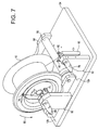
- Fig. 7 shows a view of the pallet 90 carrying the spool 10.
- an operator manually places the spool 10 on the rollers 56 and feeds the inner end 12b of the optical fiber through the eyelet 74, center hole 84 and feed finger assembly 68 such that the end 12b extends outward from the feed finger assembly 68.
- the outer end 12a of the optical fiber is fed through the eyelets 97, 95 and 83, in respective order, and then fed through the feed finger assembly 76 such that the end 12a extends outward from the feed finger assembly 76.
- the pallet 90 provides convenient access to the fiber ends 12a and 12b of the optical fiber for both automated and manual test equipment.
- the spool 10 and pallet 90 advantageously allow the optical fiber 12 to be unwound from either the inner end 12b or the outer end 12a, or both the inner end 12b and the outer end 12a simultaneously, without causing the opposite end to be disturbed.
- the spool rotates in a counter-clockwise direction (as indicated by arrow 85 in Fig. 7 ), dispensing the optical fiber. While the spool is rotating counter-clockwise, the clutch assembly 71, the pickoff assembly 70 and the feed finger assembly 68 also rotate counter-clockwise, preventing optical fiber 12 from pulling out of the feed finger assembly 68.
- the tension on the inner end 12b of the optical fiber 12 held by the fiber guide 74 exerts a counter-clockwise force on the fiber guide 74, causing the clutch assembly 71, the pickoff assembly 70, and the feed finger assembly 68 to rotate in synchronization with the spool 10.
- the optical fiber 12 extending from the spool 10 through the fiber guide 74 pulls the clutch assembly 71, the pickoff assembly 70, and the feed finger assembly 68 along with the rotating spool 10.
- the clutch assembly 71, the pickoff assembly 70 and the feed finger assembly 68 rotate counter-clockwise to remove optical fiber 12 from the lead meter barrel 15 while the spool 10 remains fixed, preventing optical fiber 12 from unwinding from the spool 10 on the outer end 12a.
- the tension on the optical fiber 12 held by the fiber guide 74 exerts a counter-clockwise (as indicated by the arrow 85) force on the clutch assembly 71, the pickoff assembly 70, and the feed finger assembly 68, causing these elements to rotate counter-clockwise as the optical fiber 12 is pulled through the feed finger assembly 68.
- the weight of the spool 10 prevents the spool 10 from rotating as the fiber 12 is unwound from the inner end 12b.
- Fig. 8 shows an overall view of an automated optical fiber measurement system 100 in accordance with the present invention.
- the system 100 may suitably include a load station 102 and an automated preparation station 104 for preparing the two ends of a length of optical fiber while is stored on a fiber storage spool.
- a spool could be, for example, a bulk storage spool or an actual fiber shipping spool.
- Shipping spool as used herein means a spool or reel containing a length of fiber and which is to be shipped to a customer.
- the system 100 may also include an optical time domain reflectrometer (OTDR) and optical dispersion test station 106, a glass geometry measurement and fiber cutoff wavelength test station 108, a fiber deflection and optical fiber coating geometry test station 110, a polarization modal dispersion (PMD) test station 112, a visual inspection station 114, and an unload station 116. While presently preferred optical fiber tests and test stations are disclosed herein, one skilled in the art will appreciate that the present invention may be utilized with fewer or additional tests and test stations, and should not be construed as limited to the tests and test stations shown and described herein.
- the automated measurement system 100 includes a conveyor system 118 for transporting the pallets 50 or 90 carrying spools 10 of optical fiber 12 from test station to test station.
- a local programmable logic controller (PLC) 121 controls the operation of the load station 102, the preparation stations 104, the visual inspection station 114, and the unload station 116. As described further below, additional local PLCs may be employed to control the operation of the other stations.
- PLC programmable logic controller
- a plurality of RF devices discussed further below, adapted to read from and/or write to the RF tag 82 attached to the pallet 50 or 90, are located in a plurality of locations adjacent to the conveyor system 118. Instructions read from the RF tag 82 control the progress of the pallet 50 or 90 through the conveyor system 118 via the local PLCs.
- the spool 10 is loaded onto the pallet 50 or 90 with the fiber ends 12a and 12b positioned such they are readily accessible to the individual test stations of system 100, as described above. As shown in Fig. 8 , the spool is loaded onto the pallet 50 or 90 of the conveyor system 118 at the load station 102. The conveyor system 118 then moves the pallet 50 or 90 to the preparation station 104.
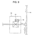
- the preparation station 104 includes a stripping device 130 for stripping the protective coating off of the optical fiber, and a cleaning device 132 for cleaning the fiber after the fiber coating has been stripped from the optical fiber.
- Both the stripping device and the cleaning device are preferably operated by pneumatic control techniques, and preferably the operation of these devices is under control of the local PLC 121 (shown in Fig. 8 ).
- the PLC 121 controls the movement of the pallet 50 or 90 while the pallet 50 or 90 is being processed by preparation station 104. After the PLC 121 has positioned the pallet 50 or 90 such that the end 12a is adjacent to the device 130, the stripping device 130 operates by initially moving below the end 12a and then rising up and positioning itself around end 12a.
- An auxiliary fiber clip engages and securely holds the end 12a between the striping device 130 and the pallet 50 or 90.
- the stripping device 130 then closes around the end 12a and retracts in a direction away from the pallet to remove the coating 13 from the end 12a
- the stripping device also includes a fiber cutting device capable of performing a rough cut on the fiber to achieve a desired length of fiber extending from the feed finger assemblies. For example, in one embodiment, about 10 cm of fiber extends from the feed finger assemblies, about 5 cm of which is fiber whose protective coating has been removed. A vacuum nozzle then removes the coating debris into a central vacuum system.
- the fiber stripping devices employed herein to remove the protective polymeric can be conventional fiber stripping devices, for example such as are available from the Miller Ripley Company, Miller Division, Cromwell, Conn, USA.
- the stripping devices employed herein are connected to pneumatic valves which may be computer controlled to control operation of the stripping devices.
- Fiber cutting can be achieved using conventional shears which are capable of performing a rough cut on the fiber.
- the pallet 50 or 90 is then moved forward so that end 12a is adjacent to the cleaning device 132.
- the cleaning device 132 operates to remove any debris from the fiber end 12a.
- the device 132 includes a cleaning head, which may be, which includes a gripper mechanism having two arms with felt or sponge pads or alternatively, a polyurethane based open cell foam material.
- a needle squirts alcohol on to the pads to moisten them.
- the gripper advances forward onto the fiber end 12a and the alcohol dampened pads close onto the fiber end 12a.
- the gripper then pulls back away from the pallet 50 or 90, thereby cleaning the fiber end 12a.
- the gripper is then rotated 90 degrees and the cleaning cycle is performed again.
- the PLC 121 then positions the pallet 50 or 90 such that the end 12b is adjacent to the stripping device 130.
- the stripping, cutting, and cleaning process is then repeated for the end 12b.
- the coating 13 could be removed and the optical fiber cleaned by manual techniques.
- the stripping and cutting device 130 and the cleaning device 132 are positioned so that, when one end of fiber is being stripped and cut to a desired length, the another end of fiber may be being cleaned.
- the automatic stripping, cutting and cleaning station is significant in that, for the first time, a fiber may be automatically prepared for testing, including removal of the protective polymeric coating and cutting of the end of the fiber, without any manual interaction from an operator.
- the pallet 50 or 90 is transported to test station 106.
- the pallet could be transported to an alternative test station if desired.
- the OTDR and optical dispersion test station 106 includes cutting devices 140, a cleaving device 142, fiber aligners 144, and fiber discarding devices 146.
- One fiber aligner 144 suitable for use with the present invention is the Model 1100 Single Fiber Aligner (PK Technology Inc., Beaverton, Oregon 97008).
- the test station 106 includes an OTDR test machine 148 and an optical dispersion test machine 150, both optically coupled to the fiber aligners 144 and controlled by one or more computers 154.
- the test station 106 also includes a local PLC 152 communicatively connected to the computer 154, an RF tag reading device 160, and an RF tag writing device 162.
- a pair of fiber clips 156 are mounted on a servo slide 158 and controlled by the local PLC 152. Operation of the test station 106, including the computer 154, is controlled by the local PLC 152.
- Fig. 10B illustrates aspects of a method 170 of automating the performance of the OTDR and optical dispersion tests utilizing the test station 106 shown in Fig. 10A .
- the RF tag reading device 160 reads the RF identification tag 52, determining routing instructions and processing instructions for the spool 10.
- the PLC determines if the routing instructions indicate that the spool 10 should be processed by the test station 106. If the local PLC 152 determines that the spool is not to be processed by the test station 106, the pallet 50 or 90 is moved to the next test station in step 173. If the local PLC 152 determines the spool is to be processed by the test station 106, the pallet 50 or 90 is moved into position adjacent to the servo slide 158 in step 174, as shown in Fig. 10A . Clips 156 are provided to grip the ends of the fiber.
- Suitable clips for use as clips 156 can be so called Optical Fiber Clips which are available from EG&G Fiber Optics, Wokingham, Berge, United Kingdom, or Optical Fiber Clips which are also available from PK Technologies Inc., Beaverton Oregon, USA.
- the fiber clips 156 preferably have a V-shaped groove therein parallel to the direction the fiber will be inserted into the clip, and into which the fiber is grasped by the clip.
- the opening and closing of the clips is preferably controlled using pneumatic control methods.
- the clips 156 are moved by the servo slide 158 to the ends 12a and 12b where the clips 156 engage and hold the optical fiber ends 12a and 12b.
- the servo slide 158 moves the clips 156 holding the fiber ends to the cleaving device 142 where the fiber ends 12a, 12b may be cleaved, or precision cut, leaving a predetermined length of optical fiber 12 protruding from each clip 156.
- the cleaving device preferably is capable of cleaving the fiber in a manner which results in a cleaved surface suitable for optical coupling, for example to one of the testing apparatus described herein. Such cleaving can be accomplished using optical fiber cleaving devices such as are available from Seimens in Germany. These fiber cutting devices are preferably also adapted to be controllable by pneumatic computer controlled devices.
- the servo slide 158 moves the clips 156 toward the fiber aligners 144, inserting an appropriate length of the fiber ends 12a, 12b into the fiber aligners 144.
- step 178 the computer 154 commands the OTDR test machine 148, which is optically connected to the fiber aligners 144 as described above, to test the optical fiber 12.
- the OTDR test machine 148 provides a measure of the fiber attenuation of the optical fiber 12 over a selected wavelength range. OTDR attenuation measurements are made at a plurality of wavelengths which are within a predetermined selected range. The measured attenuations are analyzed to produce a curve representing attenuation, i.e., spectral attenuation, for the wavelengths of the selected range.
- step 180 the computer 154 commands the optical dispersion test machine 150, which is also optically connected to the fiber aligners 144 as described above, to test the optical fiber 12.
- the optical dispersion test provides a measure of the distortion of optical signals as they propagate down optical fiber 12.
- step 182 the fiber discarding devices 146 engage and grasp the ends 12a and 12b of the optical fiber, the cutting devices 156 cut the stripped ends 12a and 12b of the optical fiber 12, and the fiber discarding devices 146 remove the pieces of optical fiber which were severed from the testing area.
- the fiber discarding devices 146 utilize a gripper mounted on a rod to grip the severed pieces of optical fiber and move them into a scrap trough.
- the scrap fiber can be removed via a vacuum which is mounted or movable to a position which is close enough to remove the scrap fiber.
- the RF tag writing device 162 preferably writes the results of the OTDR and optical dispersion tests to the RF identification tag 52.
- the conveyor 118 then transports the pallet 50 or 90 to the next test station.
- the glass geometry measurement and cutoff wavelength test station 108 includes a fiber clip 200 attached to a deployment slide 202, a cutting device 204, and a fiber discarding device 206.
- the test station 108 also includes mandrels 208a, 208b, 208c, 208d rotatably mounted on a dial plate 210.
- Mounted on each mandrel 208a, 208b, 208c, 208d are fiber gripping clips 212, 213 located at the ends of extension arms 215(a) and 215 (b).
- a stripping device 214, a cleaning device 216, and cleaving device 218 are mounted on a slide 220.
- a cutoff wavelength tester 222 and a glass measurement tester 224 are communicatively connected to a vision alignment system 226.
- the test station 108 also includes an RF tag reading device 232 and an RF tag writing device 234. Operation of the test station 108, including one or more computers 230, is controlled by a local PLC 228.
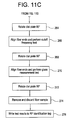
- Figs. 11B and 11C show a method 250 for automating the performance of the glass measurement and cutoff wavelength tests utilizing the test station 108 shown in Fig. 11A .
- the RF tag reading device 232 reads the RF identification tag 52, determining routing instructions and processing instructions for the spool 10.
- the local PLC 228 determines if the routing instructions indicate that the spool 10 should be processed by the test station 108. If the local PLC 228 determines that the spool 10 is not to be processed by the test station 108, the pallet 50 or 90 is moved to the next test station in step 253.
- the pallet 50 or 90 is moved into position adjacent to the slide 202 in step 254, as shown in Fig. 11A .
- the fiber clip 200 is moved by the deployment slide toward the spool 10, where the fiber clip 200 engages and grabs the fiber end 12a.
- the deployment slide 202 then moves the clip 200 away from the pallet 50 or 90, deploying a length of the optical fiber 12.
- the fiber clip 200 passes the fiber end 12a to the fiber clip 212 mounted on the mandrel 208a.
- the fiber clip 200 moves laterally outward from slide 202 towards and into communication with clip 212 on mandrel extension arm 215(a).
- step 256 the mandrel 208a rotates counter-clockwise 1.5 rotations, wrapping approximately two meters of optical fiber 12 around the mandrel 208a, which is basically a cylinder having a diameter of about 11 inches, or 280 cm.
- a fiber guide ensures proper containment of the optical fiber 12 around mandrel 208(a) while the fiber is being wound onto the mandrel.
- step 258 the clip 213 attached to the mandrel 208a engages the optical fiber 12 and the cutting device 204 performs a cut on the optical fiber 12, leaving about two inches of fiber end exposed for testing.
- test station 108 has acquired a sample length of the optical fiber 12 which is wrapped around the mandrel 208 and held by the clips 212 and 213.
- this technique is not limited to use with an 11 inch diameter mandrel, and could be employed instead on mandrels having a different diameter, e.g. 3 inches.
- step 260 the dial plate 210 rotates 90° counter-clockwise, bringing the mandrel 208a adjacent to the slide 220.
- step 262 the fiber ends held by the clips 212, 213 are stripped of their plastic coating by stripping device 214, cleaned of excess debris by cleaning device 216, and cleaved by cleaving device 218, much the same as was described above with respect the stripping, cleaving, and cleaning station illustrated in Fig. 9 .
- the stripping device 214, the cleaning device 216, and the cleaving device are movably mounted along the slide 220, and also are provided with transverse slides (not shown) which enable movement of these devices transverse to slide 220 to facilitate the stripping, cutting, and cleaning operations to the ends 12a and 12b.
- the dial plate 210 rotates 90° counter-clockwise, bringing the mandrel to face the cutoff wavelength tester 222, as illustrated by mandrel 208(c).
- Each of the rotatable mandrels are mounted on a slide located under the mandrel, which enables movement of the mandrel in the directions indicated by arrow 217.
- the entire mandrel 208(c) is moved towards cut-off tester to insert the fiber ends 12a and 112b into cut-off tester 222.
- step 266 the PLC 228 commands the computer 230 to run the cutoff wavelength tester 222 to test the sample of optical fiber.
- the computer 230 directs the vision device 226 to align the lenses of the cutoff wavelength tester 222 with the fiber ends held by the clips 212 and 213.
- the computer 230 then directs the cutoff wavelength tester 222 to test the sample of optical fiber.
- the cutoff wavelength test determines the cutoff wavelength at which the optical fiber begins to operate like a single mode optical fiber.
- step 268 the mandrel retracts back, pulling the fiber ends 12a and 12b out of cut-off tester, and dial plate 210 rotates 90° counter-clockwise, bringing the mandrel 208a adjacent to the glass measurement tester 224.
- step 270 the PLC 228 commands the computer 230 to test the sample of optical fiber.
- the vision device 226 aligns the lenses of the glass measurement tester 224 with the fiber ends and the glass measurement tester 224 tests the optical fiber.
- the glass measurement tester 224 determines relative geometrical parameters of the core and clad portions of the optical fiber sample. Additionally, the glass measurement tester 224 may measure the core and clad concentricity.
- the dial plate 210 rotates 90° counter-clockwise, bringing the mandrel 208a to face the pallet 50 or 90.
- the fiber discarding device 206 grips one of the fiber ends, the fiber clips 212, 213 release the fiber ends, and the fiber discarding device 206 removes and discards the optical fiber sample.
- the RF tag writing device 234 writes the results of cutoff wavelength and glass measurement tests to the RF identification tag 52.
- the conveyor 118 then transports the pallet 50 or 90 to the preparation station 104 before passing the pallet 50 or 90 to the next test station.
- the four mandrels 208a, 208b, 208c, 208d advantageously allow four samples of optical fiber to be processed simultaneously, reducing equipment cost and improving throughput. While a first fiber sample is being acquired and wrapped around mandrel 208a, a second fiber sample wrapped around mandrel 208b may be being stripped, cleaned, and cleaved, a third fiber sample wrapped around mandrel 208c may be undergoing cutoff wavelength testing, and a fourth fiber sample wrapped around mandrel 208d may be undergoing glass measurement testing.
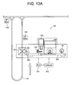
- the fiber deflection and coating geometry test station 110 includes a fiber clip 300 attached to a deployment slide 302, a cutting device 304, a fiber discarding device 306, and a coating geometry tester 308.
- An optical fiber deflection tester 310 includes a spin drive 312.
- the test station 110 also includes an RF tag identification read device 318 and an RF tag identification write device 320. Operation of the test station 110, including one or more computers 316, is controlled by a local PLC 314. According to a preferred embodiment of the present invention, two samples from each spool are processed simultaneously.
- Fig. 12B shows a method 350 for automating the performance of the fiber curl and coating geometry tests utilizing the test station 110 shown in Fig. 12A .
- the RF tag reading device 318 reads the RF identification tag 52, determining routing instructions and processing instructions for the spool 10.
- the local PLC 314 determines if the routing instructions indicate that the spool 10 should be processed by the test station 110. If the local PLC 314 determines that the spool 10 is not to be processed by the test station 110, the pallet 50 or 90 is moved to the next test station in step 353.
- the pallet 50 or 90 is moved into position adjacent to the slide 302 in step 354, as shown in Fig. 12A .
- the fiber clip 300 is moved by the deployment slide 302 toward the spool 10 where the clip 300 engages and holds the fiber end 12a.
- the deployment slide 302 moves the clip 300 away from the pallet 50 or 90, deploying a length (e.g., 8 inches) of the optical fiber.
- the cutting device 304 cuts the optical fiber, leaving a sample of the optical fiber held by the clip 300.
- the fiber clip 300 moves along the slide 302 and passes the optical fiber sample to the spin drive 312 which holds the fiber sample by an end.
- step 358 the PLC 314 commands the computer 316 to run the fiber curl tester 310.
- the optical fiber sample is rotated about its axis by the spin drive 312 while measurements of deflection versus a reference are periodically taken. From this data, a measurement of fiber curl is determined.
- the clip 300 reacquires the sample from the spin drive 312 and slides the sample along the slide 302 to the coating geometry tester 308.
- the fiber sample passes to a clamp or fiber gripping device which then rotates the sample of optical fiber into a vertical orientation and inserts it into the coating geometry tester 308.
- the PLC 314 commands the computer 316 to run the coating geometry tester 308.
- the fiber sample is placed vertically and rotated about its axis by the coating geometry tester 308 while data relative to coating and glass fiber geometry is measured. From this data, various parameters about the placement of the fiber within the coating are determined.
- step 364 the fiber sample is removed from the coating geometry tester 308 by the clamp and passed to the clip 300.
- the clip 300 moves the sample along the deployment slide 302 to the fiber discarding device 306 which acquires and discards the fiber sample.
- the RF tag writing device 320 writes the results of coating geometry and fiber deflection tests to the RF identification tag 52.
- the conveyor 118 then transports the pallet 50 or 90 to the next test station.
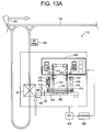
- the PMD test station 112 includes a fiber clip 400 and a gripper 401 attached to a deployment slide 402, a cutting device 404, and a PMD tester 408.
- a V-groove tool 410 with clips 414 is located adjacent to the deployment slide 402.
- the test station 112 also includes a transfer slide 412 with fiber clips 413. Stripping devices 416, cleaning devices 418, cleaving devices 420 are located adjacent to the transfer slide 412.
- the PMD tester 408 includes clips 421.
- the test station 112 also includes an RF tag identification reading device 424 and an RF tag identification writing device 426. Operation of the test station 112, including one or more computers 428, is controlled by a local PLC 430.
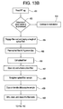
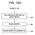
- Figs. 13B and 13C show a method 450 for automating the performance of the fiber PMD test utilizing the test station 112 shown in Fig. 13A .
- the RF tag read device 424 reads the RF identification tag 52, determining routing instructions and processing instructions for the spool 10.
- the local PLC 430 determines if the routing instructions indicate the spool 10 should be processed by the test station 112. If the local PLC 430 determines that the spool 10 is not to be processed by the test station 112, the pallet 50 or 90 is moved to the next station in a step 453.
- the pallet 50 or 90 is moved into position adjacent to the slide 402 in step 454, as shown in Fig. 13A .
- the fiber clip 400 is moved by the slide 402 toward the spool 10 where the clip 400 engages and holds the fiber end 12a and the deployment slide 402 moves the clip 400 away from the pallet 50 or 90, deploying a length (e.g., 12 inches) of the optical fiber 12 above the V-groove of the V-groove tool 410.
- the clips 414 of the V-groove tool 410 elevate and acquire the optical fiber as the clip 400 releases it.
- step 456 the cutting device 404 cuts the optical fiber, leaving a sample of the optical fiber held by the clips 414.
- the clips 414 lower the optical fiber sample to the bottom of the V-groove and the clip 414 closest to the conveyor 118 is released. Also in the step 457, air is forced through holes in the bottom of the V-groove, creating a bed of air which will allow the optical fiber sample to use its own torsional flex to unwind to an untwisted state.
- step 458 the felt-tipped gripper 401 attached to the slide 402 lowers and clamps the fiber sample at the end held by the clip 414. The gripper 401 then moves along the length of the sample to straighten it.
- the clip 414 which had previously released the optical fiber sample in the step 457 reacquires the sample.
- step 459 the clips 413 move along slide 412 to the V-groove and acquire the fiber sample from the clips 414. After acquiring the sample, the clips move slightly towards each other, allowing a small amount of sag to develop in the optical fiber sample.
- step 460 the clips 413 move the sample along the slide 412 where the ends of the optical fiber sample are stripped by stripping devices 416, cleaned by the cleaning devices 418, and cleaved by the cleaving devices 420.
- step 461 the clips 413 move along slide 412 and pass the sample to the clips 421 of the PMD tester 408 which tests the optical fiber sample.
- step 464 the sample of optical fiber is discarded by the discarding device 406.
- step 466 the RF tag writing device 426 writes the results of PMD test to the RF identification tag 52.
- the conveyor 118 then transports the pallet 50 or 90 to the next station.
- an operator manually inspects the spool 10 at the visual inspection station 114.
- the local PLC 121 routes the pallet 50 or 90 to the inspection station 114 after the spool 10 has passed all of the tests described above.
- the operator tapes the optical fiber ends 12a, 12b to the spool 10.
- an RF tag reading device 115 reads the RF identification 52 and transmits the test results to the manufacturing line, allowing the manufacturing process to be adjusted with timely feedback from the system 100.
- the conveyor 118 the transports the pallet 50 or 90 to the unload station 116.
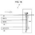
- the unload station 116 includes an unload device 500, a reject queue 502, a rework queue 504, and a passed queue 506.
- the local PLC 121 routes the pallet 50 or 90 to the unload station 116 after the spool 10 has been manually inspected or has failed one of the tests described above.
- the PLC 121 directs the unload device 500 to remove the spool 10 from the pallet 50 or 90 and place the spool in the appropriate queue.
- the empty pallet 50 or 90 then proceeds to the load station where another spool is loaded.
Landscapes
- Physics & Mathematics (AREA)
- Chemical & Material Sciences (AREA)
- Analytical Chemistry (AREA)
- General Physics & Mathematics (AREA)
- Optics & Photonics (AREA)
- Mechanical Coupling Of Light Guides (AREA)
- Testing Of Optical Devices Or Fibers (AREA)
- Light Guides In General And Applications Therefor (AREA)
- Sampling And Sample Adjustment (AREA)
Abstract
Description
- The present invention relates generally to improvements in the manufacture of optical fiber. More specifically, the present invention relates to methods and apparatus for automating the testing of optical fiber wound onto a spool.
- In the current manufacturing process for optical fiber, optical fiber is typically wound onto a spool for measurement and testing, shipping to a customer, and subsequent processing at the customer's facility. The measurement and testing of optical fiber is currently performed manually by multiple technicians, with carts carrying a number of spools being manually moved from test station to test station. At a test station a technician removes a spool from the cart and places the spool on a measurement rack. The technician then strips and removes the plastic fiber coating from both ends of the optical fiber, cleaning off excess coating and any remaining debris. The fiber ends are manipulated by the technician into a cleaver and cut. Next, the technician loads the fiber ends into a computer controlled measurement system and initiates a measurement sequence to test at least one characteristic of the optical fiber, e.g., fiber cutoff wavelength, attenuation, fiber curl, cladding diameter, or coating diameter. The fiber is then removed from the testing system and the spool returned to the cart. All of the spools on the cart or only selected spools may be tested as desired. The cart is then manually moved to the next test station for another series of tests. The amount of manual labor involved results in high labor costs and higher manufacturing costs for optical fiber.
- Accordingly, it would be highly advantageous to further automate the manual steps of optical fiber measurement and testing, reducing the time required in the measurement and testing area and thus reducing the cost of manufacturing optical fiber and providing faster feedback on the manufacturing process. Additionally, it would be highly advantageous to provide methods and apparatus for the automated testing of optical fiber which reduces the opportunity for human error and provides a more repeatable process.
- The present invention provides advantageous methods and apparatus for the automation of the testing of optical fiber. The present invention includes an automated conveyor system which moves spools of optical fiber contained on pallets from testing station to testing station. According to one aspect of the present invention, a single spool is carried by a specially designed pallet which has a number of advantageous features described further below. According to another aspect of present invention, an apparatus automatically strips, cleans, and cleaves the fiber ends once the spool reaches the apparatus. The fiber ends are then automatically manipulated into the appropriate location for a predetermined test to be performed. According to another aspect of the invention, an apparatus automatically acquires a sample length of the optical fiber and strips, cleans, and cleaves the fiber ends of the sample. The sample length of the optical fiber is then manipulated into the appropriate location for a second predetermined test to be performed.
- These and other features, aspects and advantages of the invention will be apparent to those skilled in the art from the following detailed description taken together with the accompanying drawings.
-
-
Fig. 1 shows a view of a spool which may suitably be used in conjunction with the present invention; -
Fig. 2 shows an isometric view of a pallet in accordance with the present invention; -
Figs. 3A, 3B, 3C, and 3D show, respectively, top, front, side, and isometric views of a pallet in accordance with the present invention; -
Fig. 4 shows an isometric view of the pallet ofFig. 2 carrying the spool ofFig. 1 ; -
Fig. 5 shows an isometric view of a pallet in accordance with another aspect of the present invention carrying the spool ofFig. 1 ; -
Figs. 6A, 6B, 6C, and 6D show, respectively, top, front, side, and isometric views of the pallet ofFig. 5 ; -
Fig. 7 shows an isometric view of the pallet ofFig. 5 carrying the spool ofFig. 1 . -
Fig. 8 is an overall view of an automated optical fiber testing system in accordance with the present invention; -
Fig. 9 shows a detailed view of a preparation station suitable for use in conjunction with the system ofFig. 8 ; -
Fig. 10A shows a detailed view of an optical time domain reflectrometry and optical dispersion test station suitable for use in conjunction with the system ofFig. 8 ; -
Fig. 10B is a flowchart of a method for automating the performance of the optical time domain reflectrometry and the optical dispersion tests ofFig. 10A in accordance with the present invention; -
Fig. 11A shows a detailed view of a glass measurement and cutoff wavelength test station suitable for use in conjunction with the system ofFig. 8 ; -
Figs. 11B and11C are a flowchart of a method for automating the performance of the glass measurement and cutoff frequency tests ofFig. 11A in accordance with the present invention; -
Fig. 12A shows a detailed view of a fiber deflection test station and coating geometry test station suitable for use in conjunction with the system ofFig. 8 ; -
Fig. 12B is a flowchart of a method for automating the performance of the optical fiber deflection and coating geometry tests ofFig. 12A in accordance with the present invention; -
Fig. 13A shows a detailed view of a polarization modal dispersion test station suitable for use in conjunction with the system ofFig. 8 ; -
Figs. 13B and13C are a flowchart of a method for automating the performance of the polarization modal dispersion test ofFig. 13A in accordance with the present invention; and -
Fig. 14 shows a detailed view of an unload station suitable for use in conjunction with the system ofFig. 8 . - The present invention now will be described more fully with reference to the accompanying drawings, in which several currently preferred embodiments of the invention are shown. However, this invention may be embodied in various forms and should not be construed as limited to the exemplary embodiments set forth herein. Rather, these representative embodiments are described in detail so that this disclosure will be thorough and complete, and will fully convey the scope, structure, operation, functionality, and potential of applicability of the invention to those skilled in the art.
- Referring to the drawings,
Fig. 1 shows a top view of aspool 10 which may be advantageously used in conjunction with the present invention. Thespool 10 comprises aprimary barrel 14 and alead meter barrel 15 separated from each other by anoutboard flange 16. A length ofoptical fiber 12 has been wound onto theprimary barrel 14 and thelead meter barrel 15 during the manufacturing process. In a presently preferred embodiment,spool 10 may be, for example, a "single" spool, having 25 km of optical fiber wound onto theprimary barrel 14, or a "double" spool containing 50 km of optical fiber wound onto theprimary barrel 14. A short length of theoptical fiber 12 has been wound onto thelead meter barrel 15. Theoutboard flange 16 has aslot 17 providing a path for theoptical fiber 12 between thelead meter barrel 15 and theprimary barrel 14. As seen from the top view ofFig. 1 , anouter end 12a of theoptical fiber 12 extends from the underside of theprimary barrel 14 and aninner end 12b extends from the underside of thelead meter barrel 15. Theoptical fiber 12 also typically includes aplastic coating 13. Further details of a presently preferredspool 10 for use in conjunction with the present invention are provided inU.S. Patent Application Serial No. 60/115,540, filed on January 12, 1999 -
Fig. 2 shows an isometric view of apallet 50 in accordance with a first embodiment of the present invention. Thepallet 50 is adapted to carry thespool 10 ofoptical fiber 12 such that the fiber ends 12a and 12b are available to the testing equipment of automatedfiber measurement system 100 described below. Thepallet 50 includes aroller assembly 52 mounted on a base 54 adapted for carrying thespool 10. Theroller assembly 52 includes a pair ofrollers 56 and a pair ofbase plates 58. Also mounted on thebase 54 arevertical brackets upright guide roller 64. As shown inFigs. 3A and 3C , aguide bar 66 is mounted to thebase 54. Afeed finger assembly 68, apickoff assembly 70, and aclutch assembly 71 are rotationally mounted on thevertical bracket 60. Mounted to thepickoff assembly 70 is afiber guide 72 which includes aneyelet 74. Afeed finger assembly 76, aguide roller 80, and afiberguide 81 including aneyelet 83 are mounted on thevertical bracket 62. As best seen inFig. 4 , acenter hole 84 extends through the rotational center of thefeed finger assembly 68, thepickoff assembly 70, and thevertical bracket 60. - As shown in
Fig. 3D , a radio frequency (RF)identification tag 82 identifying thespool 10 is attached to thevertical bracket 60. In addition to identifying thespool 10, theRF tag 82 is capable of storing information which has been written to it, allowing theRF tag 82 to provide a travelling database for thespool 10 as it passes through thesystem 100. TheRF tag 82 provides processing instructions for individual test stations and stores the data of the test results. As eachspool 10 is processed by the individual test stations of thesystem 100, the results of each of the tests are written to theRF tag 82. Thus, when thespool 10 has been processed by each of the appropriate test stations, theRF tag 82 contains the test results of all the tests performed. Additionally, theRF tag 82 also contains the routing instructions for thespool 10, indicating which test stations need to process thespool 10. -
Fig. 4 shows a view of thepallet 50 carrying thespool 10. To load thespool 10 onto thepallet 50, an operator manually places thespool 10 on therollers 56 and feeds theinner end 12b of the optical fiber fromlead meter barrel 15 through theeyelet 74,center hole 84 and feedfinger assembly 68 such that theend 12b extends outward from thefeed finger assembly 68. Theouter end 12a of the optical fiber fromprimary barrel 14 is first fed around theguide roller 64, overguide roller 80, and then fed through theeyelet 83 and feedfinger assembly 76 such that theouter end 12a extends outward from thefeed finger assembly 76. Thus, as shown inFig. 4 , thepallet 50 provides convenient access to theends - Furthermore, the
spool 10 andpallet 50 advantageously allow theoptical fiber 12 to be unwound from either theinner end 12b or theouter end 12a individually, or both theinner end 12b andouter end 12a simultaneously, without causing the opposite end to be disturbed. This allows both automated and manual test equipment to readily acquire samples of optical fiber from either or both of the fiber ends 12a and 12b. The fiber ends 12a and 12b may also be readily engaged and pulled or directed to test stations, allowing theoptical fiber 12 to be tested while wound onto thespool 10. - The
clutch mechanism 71 includes at least asingle wheel 150 that is forced into contact with thespool 10. Thewheel 150 onclutch mechanism 71 rotates in a single direction which enables fiber to be pulled fromfiber end 12b, in this case the direction indicated by arrow 151. Asoptical fiber 12 is unwound from theouter end 12a, thespool 10 rotates in a counter-clockwise direction (as indicated byarrow 85 inFig. 4 ), dispensing theoptical fiber 12. Because thewheel 150 ofclutch assembly 71 does not rotate in a direction which is counter to the direction indicated by arrow 151, the force caused by the counterclockwise rotation ofspool 10 causes the entireclutch assembly 71,pickoff assembly 70, and feedfinger assembly 68 to rotate counter-clockwise around the axis ofcenter hole 84 offeed finger assembly 68. This rotation keeps theinner end 12b ofoptical fiber 12 from being removed from thespool 10.
As theouter end 12a ofoptical fiber 12 is unwound from the spool, the tension on theinner end 12b of theoptical fiber 12 held by thefiber guide eyelet 74 exerts a counter-clockwise force on thefiber guide 74, causing theclutch assembly 71, thepickoff assembly 70, and thefeed finger assembly 68 to rotate in synchronization with thespool 10. In other words, as thespool 10 is rotated counter-clockwise byoptical fiber 12 being unwound from theouter end 12a, theoptical fiber 12 extending from thespool 10 through theeyelet 74 offiber guide 72 pulls theclutch assembly 71, thepickoff assembly 70, and thefeed finger assembly 68 along with the rotatingspool 10. - As
optical fiber 12 is unwound from theinner end 12b, theclutch assembly 71, thepickoff assembly 70 and thefeed finger assembly 68 rotate counter-clockwise (as indicated by the arrow 85), causingwheel 150 to rotate in the direction indicated by arrow 151, to thereby removeoptical fiber 12 from thelead meter barrel 15 while thespool 10 remains fixed, preventingoptical fiber 12 from unwinding from thespool 10 on theouter end 12a. The weight of thespool 10 prevents thespool 10 from rotating as thefiber 12 is unwound from theinner end 12b. The tension caused by theoptical fiber 12 being pulled throughfiber guide eyelet 74 exerts a counter-clockwise force onfiber guide 72, and thusclutch assembly 71, thepickoff assembly 70, and thefeed finger assembly 68, causing these elements to rotate in a counterclockwise direction as theoptical fiber 12 is pulled through thefeed finger assembly 68. - Alternatively, fiber can be removed from
spool 10 simultaneously by simply pulling on both ends of fiber at the same time. -
Fig. 5 shows an isometric view of apallet 90 in accordance with a second embodiment of the present invention. Since many components are arranged in the same manner as the first embodiment, like reference numerals are used to designate elements common to the two embodiments. Thepallet 90 is adapted to carry thespool 10 ofoptical fiber 12 such that the fiber ends 12a and 12b are available to the testing equipment ofsystem 20 described above. Thepallet 90 includes aroller assembly 52 mounted on a base 54 adapted for carrying thespool 10. Theroller assembly 52 includes a pair ofrollers 56 and a pair ofbase plates 58. Mounted on thebase 54 arevertical brackets Figs. 6A and 6C , avertical bracket 92 is also mounted on thebase 54. As shown inFig. 5 , afeed finger assembly 68, apickoff assembly 70, and aclutch assembly 71 are rotationally mounted on thevertical bracket 60. Mounted to thepickoff assembly 70 is afiber guide 72 which includes aneyelet 74. Afeed finger assembly 76 and afiber guide 81 including aneyelet 83 are mounted on thevertical bracket 62. As best seen inFig. 6B , afiber guide 94 including aneyelet 95 and afiber guide 96 including aneyelet 97 are mounted on thevertical bracket 92. Acenter hole 84 extends through the rotational center of thefeed finger assembly 68, thepickoff assembly 70, and thevertical bracket 60. - As shown in
Fig. 6D , a radio frequency (RF)identification tag 82 identifying thespool 10 is attached to thevertical bracket 60. In addition to identifying thespool 10, theRF tag 82 is capable of storing information which has been written to it, allowing theRF tag 82 to provide a traveling database for thespool 10 as it passes through thesystem 20. TheRF tag 82 provides processing instructions for individual test stations and stores the data of the test results. As eachspool 10 is processed by the individual test stations of thesystem 20, the results of the tests are written to theRF tag 82. TheRF tag 82 also contains the routing instructions for thespool 10, indicating which test stations need to process thespool 10. -
Fig. 7 shows a view of thepallet 90 carrying thespool 10. To load thespool 10 onto thepallet 90, an operator manually places thespool 10 on therollers 56 and feeds theinner end 12b of the optical fiber through theeyelet 74,center hole 84 and feedfinger assembly 68 such that theend 12b extends outward from thefeed finger assembly 68. Theouter end 12a of the optical fiber is fed through theeyelets feed finger assembly 76 such that theend 12a extends outward from thefeed finger assembly 76. Thus, as shown inFigs. 5 and7 , thepallet 90 provides convenient access to the fiber ends 12a and 12b of the optical fiber for both automated and manual test equipment. - Furthermore, the
spool 10 andpallet 90 advantageously allow theoptical fiber 12 to be unwound from either theinner end 12b or theouter end 12a, or both theinner end 12b and theouter end 12a simultaneously, without causing the opposite end to be disturbed. As optical fiber is unwound from theouter end 12a, the spool rotates in a counter-clockwise direction (as indicated byarrow 85 inFig. 7 ), dispensing the optical fiber. While the spool is rotating counter-clockwise, theclutch assembly 71, thepickoff assembly 70 and thefeed finger assembly 68 also rotate counter-clockwise, preventingoptical fiber 12 from pulling out of thefeed finger assembly 68. As theoptical fiber 12 is unwound from theouter end 12a, the tension on theinner end 12b of theoptical fiber 12 held by thefiber guide 74 exerts a counter-clockwise force on thefiber guide 74, causing theclutch assembly 71, thepickoff assembly 70, and thefeed finger assembly 68 to rotate in synchronization with thespool 10. In other words, as thespool 10 is rotated counter-clockwise byoptical fiber 12 being unwound from theouter end 12a, theoptical fiber 12 extending from thespool 10 through thefiber guide 74 pulls theclutch assembly 71, thepickoff assembly 70, and thefeed finger assembly 68 along with the rotatingspool 10. - As
optical fiber 12 is unwound from theinner end 12b, theclutch assembly 71, thepickoff assembly 70 and thefeed finger assembly 68 rotate counter-clockwise to removeoptical fiber 12 from thelead meter barrel 15 while thespool 10 remains fixed, preventingoptical fiber 12 from unwinding from thespool 10 on theouter end 12a.
The tension on theoptical fiber 12 held by thefiber guide 74 exerts a counter-clockwise (as indicated by the arrow 85) force on theclutch assembly 71, thepickoff assembly 70, and thefeed finger assembly 68, causing these elements to rotate counter-clockwise as theoptical fiber 12 is pulled through thefeed finger assembly 68. The weight of thespool 10 prevents thespool 10 from rotating as thefiber 12 is unwound from theinner end 12b. -
Fig. 8 shows an overall view of an automated opticalfiber measurement system 100 in accordance with the present invention. Thesystem 100 may suitably include aload station 102 and anautomated preparation station 104 for preparing the two ends of a length of optical fiber while is stored on a fiber storage spool. Such a spool could be, for example, a bulk storage spool or an actual fiber shipping spool. Shipping spool as used herein means a spool or reel containing a length of fiber and which is to be shipped to a customer. Thesystem 100 may also include an optical time domain reflectrometer (OTDR) and opticaldispersion test station 106, a glass geometry measurement and fiber cutoffwavelength test station 108, a fiber deflection and optical fiber coatinggeometry test station 110, a polarization modal dispersion (PMD)test station 112, avisual inspection station 114, and an unloadstation 116. While presently preferred optical fiber tests and test stations are disclosed herein, one skilled in the art will appreciate that the present invention may be utilized with fewer or additional tests and test stations, and should not be construed as limited to the tests and test stations shown and described herein. Theautomated measurement system 100 includes aconveyor system 118 for transporting thepallets spools 10 ofoptical fiber 12 from test station to test station. A local programmable logic controller (PLC) 121 controls the operation of theload station 102, thepreparation stations 104, thevisual inspection station 114, and the unloadstation 116. As described further below, additional local PLCs may be employed to control the operation of the other stations. A plurality of RF devices, discussed further below, adapted to read from and/or write to theRF tag 82 attached to thepallet conveyor system 118. Instructions read from theRF tag 82 control the progress of thepallet conveyor system 118 via the local PLCs. - To begin processing, the
spool 10 is loaded onto thepallet system 100, as described above. As shown inFig. 8 , the spool is loaded onto thepallet conveyor system 118 at theload station 102. Theconveyor system 118 then moves thepallet preparation station 104. - As seen in
Fig. 9 , thepreparation station 104 includes a strippingdevice 130 for stripping the protective coating off of the optical fiber, and acleaning device 132 for cleaning the fiber after the fiber coating has been stripped from the optical fiber. Both the stripping device and the cleaning device are preferably operated by pneumatic control techniques, and preferably the operation of these devices is under control of the local PLC 121 (shown inFig. 8 ). Additionally, thePLC 121 controls the movement of thepallet pallet preparation station 104. After thePLC 121 has positioned thepallet end 12a is adjacent to thedevice 130, the strippingdevice 130 operates by initially moving below theend 12a and then rising up and positioning itself aroundend 12a. An auxiliary fiber clip (not shown) engages and securely holds theend 12a between thestriping device 130 and thepallet device 130 then closes around theend 12a and retracts in a direction away from the pallet to remove thecoating 13 from theend 12a The stripping device also includes a fiber cutting device capable of performing a rough cut on the fiber to achieve a desired length of fiber extending from the feed finger assemblies. For example, in one embodiment, about 10 cm of fiber extends from the feed finger assemblies, about 5 cm of which is fiber whose protective coating has been removed. A vacuum nozzle then removes the coating debris into a central vacuum system. - The fiber stripping devices employed herein to remove the protective polymeric can be conventional fiber stripping devices, for example such as are available from the Miller Ripley Company, Miller Division, Cromwell, Conn, USA. Preferably the stripping devices employed herein are connected to pneumatic valves which may be computer controlled to control operation of the stripping devices. Fiber cutting can be achieved using conventional shears which are capable of performing a rough cut on the fiber.
- The
pallet end 12a is adjacent to thecleaning device 132. Thecleaning device 132 operates to remove any debris from thefiber end 12a. Thedevice 132 includes a cleaning head, which may be, which includes a gripper mechanism having two arms with felt or sponge pads or alternatively, a polyurethane based open cell foam material. First, a needle squirts alcohol on to the pads to moisten them. Then the gripper advances forward onto thefiber end 12a and the alcohol dampened pads close onto thefiber end 12a. The gripper then pulls back away from thepallet fiber end 12a. Preferably, the gripper is then rotated 90 degrees and the cleaning cycle is performed again. - The
PLC 121 then positions thepallet end 12b is adjacent to the strippingdevice 130. The stripping, cutting, and cleaning process is then repeated for theend 12b. Alternatively, thecoating 13 could be removed and the optical fiber cleaned by manual techniques. Preferably, the stripping and cuttingdevice 130 and thecleaning device 132 are positioned so that, when one end of fiber is being stripped and cut to a desired length, the another end of fiber may be being cleaned. The automatic stripping, cutting and cleaning station is significant in that, for the first time, a fiber may be automatically prepared for testing, including removal of the protective polymeric coating and cutting of the end of the fiber, without any manual interaction from an operator. - In the embodiment illustrated in
Fig. 8 , after an appropriate length of eachfiber end 12A and 12b has been stripped, cut, and cleaned, thepallet station 106. Alternatively, however, the pallet could be transported to an alternative test station if desired. As shown inFig. 10A , the OTDR and opticaldispersion test station 106 includes cuttingdevices 140, acleaving device 142,fiber aligners 144, andfiber discarding devices 146. Onefiber aligner 144 suitable for use with the present invention is the Model 1100 Single Fiber Aligner (PK Technology Inc., Beaverton, Oregon 97008). Thetest station 106 includes anOTDR test machine 148 and an opticaldispersion test machine 150, both optically coupled to thefiber aligners 144 and controlled by one ormore computers 154. Thetest station 106 also includes alocal PLC 152 communicatively connected to thecomputer 154, an RFtag reading device 160, and an RFtag writing device 162. A pair offiber clips 156 are mounted on aservo slide 158 and controlled by thelocal PLC 152. Operation of thetest station 106, including thecomputer 154, is controlled by thelocal PLC 152.
Fig. 10B illustrates aspects of amethod 170 of automating the performance of the OTDR and optical dispersion tests utilizing thetest station 106 shown inFig. 10A . In afirst step 171, the RFtag reading device 160 reads theRF identification tag 52, determining routing instructions and processing instructions for thespool 10. In asecond step 172, the PLC determines if the routing instructions indicate that thespool 10 should be processed by thetest station 106. If thelocal PLC 152 determines that the spool is not to be processed by thetest station 106, thepallet step 173. If thelocal PLC 152 determines the spool is to be processed by thetest station 106, thepallet servo slide 158 instep 174, as shown inFig. 10A .Clips 156 are provided to grip the ends of the fiber. Suitable clips for use asclips 156 can be so called Optical Fiber Clips which are available from EG&G Fiber Optics, Wokingham, Berge, United Kingdom, or Optical Fiber Clips which are also available from PK Technologies Inc., Beaverton Oregon, USA. The fiber clips 156 preferably have a V-shaped groove therein parallel to the direction the fiber will be inserted into the clip, and into which the fiber is grasped by the clip. The opening and closing of the clips is preferably controlled using pneumatic control methods. Theclips 156 are moved by theservo slide 158 to theends clips 156 engage and hold the optical fiber ends 12a and 12b. Instep 175, theservo slide 158 moves theclips 156 holding the fiber ends to thecleaving device 142 where the fiber ends 12a, 12b may be cleaved, or precision cut, leaving a predetermined length ofoptical fiber 12 protruding from eachclip 156. The cleaving device preferably is capable of cleaving the fiber in a manner which results in a cleaved surface suitable for optical coupling, for example to one of the testing apparatus described herein. Such cleaving can be accomplished using optical fiber cleaving devices such as are available from Seimens in Germany. These fiber cutting devices are preferably also adapted to be controllable by pneumatic computer controlled devices. After an optical quality cleave has been made, instep 176 theservo slide 158 moves theclips 156 toward thefiber aligners 144, inserting an appropriate length of the fiber ends 12a, 12b into thefiber aligners 144. - Next, in
step 178, thecomputer 154 commands theOTDR test machine 148, which is optically connected to thefiber aligners 144 as described above, to test theoptical fiber 12. TheOTDR test machine 148 provides a measure of the fiber attenuation of theoptical fiber 12 over a selected wavelength range. OTDR attenuation measurements are made at a plurality of wavelengths which are within a predetermined selected range. The measured attenuations are analyzed to produce a curve representing attenuation, i.e., spectral attenuation, for the wavelengths of the selected range. - Next, in
step 180, thecomputer 154 commands the opticaldispersion test machine 150, which is also optically connected to thefiber aligners 144 as described above, to test theoptical fiber 12. The optical dispersion test provides a measure of the distortion of optical signals as they propagate downoptical fiber 12. Next, instep 182, thefiber discarding devices 146 engage and grasp theends devices 156 cut the stripped ends 12a and 12b of theoptical fiber 12, and thefiber discarding devices 146 remove the pieces of optical fiber which were severed from the testing area. Thefiber discarding devices 146 utilize a gripper mounted on a rod to grip the severed pieces of optical fiber and move them into a scrap trough. Alternatively, the scrap fiber can be removed via a vacuum which is mounted or movable to a position which is close enough to remove the scrap fiber. Next, instep 184, the RFtag writing device 162 preferably writes the results of the OTDR and optical dispersion tests to theRF identification tag 52. Theconveyor 118 then transports thepallet - As shown in
Fig. 11A , the glass geometry measurement and cutoffwavelength test station 108 includes afiber clip 200 attached to adeployment slide 202, acutting device 204, and afiber discarding device 206. Thetest station 108 also includesmandrels dial plate 210. Mounted on eachmandrel fiber gripping clips device 214, acleaning device 216, and cleavingdevice 218 are mounted on aslide 220. Acutoff wavelength tester 222 and aglass measurement tester 224 are communicatively connected to avision alignment system 226. Thetest station 108 also includes an RF tag reading device 232 and an RFtag writing device 234. Operation of thetest station 108, including one ormore computers 230, is controlled by alocal PLC 228. -
Figs. 11B and11C show amethod 250 for automating the performance of the glass measurement and cutoff wavelength tests utilizing thetest station 108 shown inFig. 11A . In afirst step 251, the RF tag reading device 232 reads theRF identification tag 52, determining routing instructions and processing instructions for thespool 10. In asecond step 252, thelocal PLC 228 determines if the routing instructions indicate that thespool 10 should be processed by thetest station 108. If thelocal PLC 228 determines that thespool 10 is not to be processed by thetest station 108, thepallet step 253. If thelocal PLC 228 determines that thespool 10 is to be processed by thetest station 108, thepallet slide 202 instep 254, as shown inFig. 11A . Thefiber clip 200 is moved by the deployment slide toward thespool 10, where thefiber clip 200 engages and grabs thefiber end 12a. Thedeployment slide 202 then moves theclip 200 away from thepallet optical fiber 12. Instep 255, thefiber clip 200 passes thefiber end 12a to thefiber clip 212 mounted on themandrel 208a. During this step, thefiber clip 200 moves laterally outward fromslide 202 towards and into communication withclip 212 on mandrel extension arm 215(a).
Next, instep 256, themandrel 208a rotates counter-clockwise 1.5 rotations, wrapping approximately two meters ofoptical fiber 12 around themandrel 208a, which is basically a cylinder having a diameter of about 11 inches, or 280 cm. During this step, a fiber guide ensures proper containment of theoptical fiber 12 around mandrel 208(a) while the fiber is being wound onto the mandrel. Next, instep 258, theclip 213 attached to themandrel 208a engages theoptical fiber 12 and thecutting device 204 performs a cut on theoptical fiber 12, leaving about two inches of fiber end exposed for testing. Thus,test station 108 has acquired a sample length of theoptical fiber 12 which is wrapped around the mandrel 208 and held by theclips - In
step 260, thedial plate 210 rotates 90° counter-clockwise, bringing themandrel 208a adjacent to theslide 220. Innext step 262, the fiber ends held by theclips device 214, cleaned of excess debris by cleaningdevice 216, and cleaved by cleavingdevice 218, much the same as was described above with respect the stripping, cleaving, and cleaning station illustrated inFig. 9 . The strippingdevice 214, thecleaning device 216, and the cleaving device are movably mounted along theslide 220, and also are provided with transverse slides (not shown) which enable movement of these devices transverse to slide 220 to facilitate the stripping, cutting, and cleaning operations to theends step 264, thedial plate 210 rotates 90° counter-clockwise, bringing the mandrel to face thecutoff wavelength tester 222, as illustrated by mandrel 208(c). Each of the rotatable mandrels are mounted on a slide located under the mandrel, which enables movement of the mandrel in the directions indicated byarrow 217. To interface the fiber ends 12a and 12b with cut-offtester 222, the entire mandrel 208(c) is moved towards cut-off tester to insert the fiber ends 12a and 112b into cut-offtester 222. - Next, in
step 266, thePLC 228 commands thecomputer 230 to run thecutoff wavelength tester 222 to test the sample of optical fiber. In thisstep 266, thecomputer 230 directs thevision device 226 to align the lenses of thecutoff wavelength tester 222 with the fiber ends held by theclips computer 230 then directs thecutoff wavelength tester 222 to test the sample of optical fiber. The cutoff wavelength test determines the cutoff wavelength at which the optical fiber begins to operate like a single mode optical fiber. - Then, in
step 268, the mandrel retracts back, pulling the fiber ends 12a and 12b out of cut-off tester, anddial plate 210 rotates 90° counter-clockwise, bringing themandrel 208a adjacent to theglass measurement tester 224. Instep 270, thePLC 228 commands thecomputer 230 to test the sample of optical fiber. In thisstep 270, thevision device 226 aligns the lenses of theglass measurement tester 224 with the fiber ends and theglass measurement tester 224 tests the optical fiber. Theglass measurement tester 224 determines relative geometrical parameters of the core and clad portions of the optical fiber sample. Additionally, theglass measurement tester 224 may measure the core and clad concentricity. - As shown in
step 272, thedial plate 210 rotates 90° counter-clockwise, bringing themandrel 208a to face thepallet step 274, thefiber discarding device 206 grips one of the fiber ends, the fiber clips 212, 213 release the fiber ends, and thefiber discarding device 206 removes and discards the optical fiber sample.
Next, instep 276, the RFtag writing device 234 writes the results of cutoff wavelength and glass measurement tests to theRF identification tag 52. Theconveyor 118 then transports thepallet preparation station 104 before passing thepallet - The four
mandrels mandrel 208a, a second fiber sample wrapped aroundmandrel 208b may be being stripped, cleaned, and cleaved, a third fiber sample wrapped aroundmandrel 208c may be undergoing cutoff wavelength testing, and a fourth fiber sample wrapped aroundmandrel 208d may be undergoing glass measurement testing. - As shown in
Fig. 12A , the fiber deflection and coatinggeometry test station 110 includes afiber clip 300 attached to adeployment slide 302, acutting device 304, a fiber discarding device 306, and acoating geometry tester 308. An opticalfiber deflection tester 310 includes aspin drive 312. Thetest station 110 also includes an RF tag identification readdevice 318 and an RF tagidentification write device 320. Operation of thetest station 110, including one ormore computers 316, is controlled by alocal PLC 314. According to a preferred embodiment of the present invention, two samples from each spool are processed simultaneously. -
Fig. 12B shows amethod 350 for automating the performance of the fiber curl and coating geometry tests utilizing thetest station 110 shown inFig. 12A . Infirst step 351, the RFtag reading device 318 reads theRF identification tag 52, determining routing instructions and processing instructions for thespool 10. In asecond step 352, thelocal PLC 314 determines if the routing instructions indicate that thespool 10 should be processed by thetest station 110. If thelocal PLC 314 determines that thespool 10 is not to be processed by thetest station 110, thepallet step 353. If thelocal PLC 314 determines thespool 10 is to be processed by thetest station 110, thepallet slide 302 instep 354, as shown inFig. 12A . Thefiber clip 300 is moved by thedeployment slide 302 toward thespool 10 where theclip 300 engages and holds thefiber end 12a. Thedeployment slide 302 moves theclip 300 away from thepallet step 355, thecutting device 304 cuts the optical fiber, leaving a sample of the optical fiber held by theclip 300. In step 356, thefiber clip 300 moves along theslide 302 and passes the optical fiber sample to the spin drive 312 which holds the fiber sample by an end. - Next, in
step 358, thePLC 314 commands thecomputer 316 to run thefiber curl tester 310. The optical fiber sample is rotated about its axis by the spin drive 312 while measurements of deflection versus a reference are periodically taken. From this data, a measurement of fiber curl is determined. Instep 360, theclip 300 reacquires the sample from thespin drive 312 and slides the sample along theslide 302 to thecoating geometry tester 308. Instep 362, the fiber sample passes to a clamp or fiber gripping device which then rotates the sample of optical fiber into a vertical orientation and inserts it into thecoating geometry tester 308. ThePLC 314 commands thecomputer 316 to run thecoating geometry tester 308. In this test, the fiber sample is placed vertically and rotated about its axis by thecoating geometry tester 308 while data relative to coating and glass fiber geometry is measured. From this data, various parameters about the placement of the fiber within the coating are determined. Next, instep 364, the fiber sample is removed from thecoating geometry tester 308 by the clamp and passed to theclip 300. Theclip 300 moves the sample along thedeployment slide 302 to the fiber discarding device 306 which acquires and discards the fiber sample. Instep 366, the RFtag writing device 320 writes the results of coating geometry and fiber deflection tests to theRF identification tag 52. Theconveyor 118 then transports thepallet - As shown in
Fig. 13A , thePMD test station 112 includes afiber clip 400 and agripper 401 attached to adeployment slide 402, acutting device 404, and aPMD tester 408. A V-groove tool 410 withclips 414 is located adjacent to thedeployment slide 402. Thetest station 112 also includes atransfer slide 412 with fiber clips 413. Strippingdevices 416, cleaningdevices 418, cleavingdevices 420 are located adjacent to thetransfer slide 412. ThePMD tester 408 includesclips 421. Thetest station 112 also includes an RF tagidentification reading device 424 and an RF tagidentification writing device 426. Operation of thetest station 112, including one ormore computers 428, is controlled by alocal PLC 430. - One exemplary type of PMD tester suitable for use with the present invention is described in
U.S. Provisional Patent Application Serial No. 60/127107, filed on March 31, 1999 -
Figs. 13B and13C show a method 450 for automating the performance of the fiber PMD test utilizing thetest station 112 shown inFig. 13A . In afirst step 451, the RF tag readdevice 424 reads theRF identification tag 52, determining routing instructions and processing instructions for thespool 10. In asecond step 452, thelocal PLC 430 determines if the routing instructions indicate thespool 10 should be processed by thetest station 112. If thelocal PLC 430 determines that thespool 10 is not to be processed by thetest station 112, thepallet step 453. If thelocal PLC 430 determines thespool 10 is to be processed by thetest station 112, thepallet slide 402 instep 454, as shown inFig. 13A . Thefiber clip 400 is moved by theslide 402 toward thespool 10 where theclip 400 engages and holds thefiber end 12a and thedeployment slide 402 moves theclip 400 away from thepallet optical fiber 12 above the V-groove of the V-groove tool 410. Instep 455, theclips 414 of the V-groove tool 410 elevate and acquire the optical fiber as theclip 400 releases it. Instep 456, thecutting device 404 cuts the optical fiber, leaving a sample of the optical fiber held by theclips 414. Instep 457, theclips 414 lower the optical fiber sample to the bottom of the V-groove and theclip 414 closest to theconveyor 118 is released. Also in thestep 457, air is forced through holes in the bottom of the V-groove, creating a bed of air which will allow the optical fiber sample to use its own torsional flex to unwind to an untwisted state. Instep 458, the felt-tippedgripper 401 attached to theslide 402 lowers and clamps the fiber sample at the end held by theclip 414. Thegripper 401 then moves along the length of the sample to straighten it. Theclip 414 which had previously released the optical fiber sample in thestep 457 reacquires the sample. - Next, in
step 459, theclips 413 move alongslide 412 to the V-groove and acquire the fiber sample from theclips 414. After acquiring the sample, the clips move slightly towards each other, allowing a small amount of sag to develop in the optical fiber sample. Instep 460, theclips 413 move the sample along theslide 412 where the ends of the optical fiber sample are stripped by strippingdevices 416, cleaned by thecleaning devices 418, and cleaved by the cleavingdevices 420. In step 461, theclips 413 move alongslide 412 and pass the sample to theclips 421 of thePMD tester 408 which tests the optical fiber sample. Instep 464, the sample of optical fiber is discarded by the discarding device 406. Instep 466, the RFtag writing device 426 writes the results of PMD test to theRF identification tag 52. Theconveyor 118 then transports thepallet - At the
visual inspection station 114 shown inFig. 8 , an operator manually inspects thespool 10 at thevisual inspection station 114. Thelocal PLC 121 routes thepallet inspection station 114 after thespool 10 has passed all of the tests described above. In addition to inspecting thespool 10, the operator tapes the optical fiber ends 12a, 12b to thespool 10. When thepallet visual inspection station 114, an RFtag reading device 115 reads theRF identification 52 and transmits the test results to the manufacturing line, allowing the manufacturing process to be adjusted with timely feedback from thesystem 100. Theconveyor 118 the transports thepallet station 116. - As shown in
Fig. 14 , the unloadstation 116 includes an unloaddevice 500, areject queue 502, arework queue 504, and a passedqueue 506. Thelocal PLC 121 routes thepallet station 116 after thespool 10 has been manually inspected or has failed one of the tests described above. When thepallet station 116, thePLC 121 directs the unloaddevice 500 to remove thespool 10 from thepallet empty pallet - It will be apparent to those skilled in the art that various modifications and variations can be made in the present invention without departing from the spirit and scope of the present invention. Thus, it is intended that the present invention cover the modifications and variations of this invention provided they come within the scope of the appended claims and their equivalents.
Claims (20)
- A pallet adapted for carrying a spool of optical fiber comprising:a mounting device adapted for holding a spool of optical fiber; anda first structure adapted for holding a first end of the optical fiber such that the first end of the optical fiber extends outward in a such a manner as to provide easy access to the first end.
- The pallet of claim 1 further comprising:a second structure adapted for holding a second end of the optical fiber such that the second end of the optical fiber extends outward in a such a manner as to provide easy access to the second end.
- The pallet of claim 2 wherein:the first structure is further adapted to allow optical fiber to be unwound from the first end without disturbing the second end of the optical fiber; andthe second structure is further adapted to allow optical fiber to be unwound from the second end without disturbing the first end.
- The pallet of claim 3 wherein:the first structure and the second structure are further adapted to allow optical fiber to be unwound from both the first end and the second end simultaneously.
- The pallet of claim 1 wherein the pallet is further adapted for carrying the spool of optical fiber to an optical fiber test station.
- The pallet of claim 1 wherein the pallet is further adapted for use with an automated optical fiber test system.
- The pallet of claim 1 wherein the pallet is further adapted for use with a conveyor system to carry the spool of optical fiber from a first automated test station to second automated test station.
- The pallet of claim 1 further comprising:a data storage device attached to the pallet adapted to be read from and written to.
- The pallet of claim 8 wherein the data storage device identifies the spool of optical fiber and provides a database of at least one test result.
- A pallet adapted for carrying a spool of optical fiber comprising:a base;a spool holding apparatus mounted on the base adapted for holding the spool of optical fiber;a first feed finger assembly attached to the base adapted for holding a first end of the optical fiber;a second feed finger assembly attached to the base adapted for holding the second end of the optical fiber;wherein the pallet is adapted to allow optical fiber to be unwound from the first end without disturbing a second end of the optical fiber, and to allow optical fiber to be unwound from the second end without disturbing the first end.
- A pallet adapted for carrying a spool of optical fiber comprising:a base;a spool holding apparatus mounted on the base adapted for holding the spool of optical fiber;a first vertical bracket mounted to the base;a second vertical bracket mounted to the base;a first feed finger assembly rotationally mounted to the first vertical bracket adapted for holding a first end of the optical fiber and allowing optical fiber to be unwound from the first end without disturbing a second end of the optical fiber; anda second feed finger assembly mounted to the second vertical bracket adapted for holding the second end of the optical fiber and allowing optical fiber to be unwound from the second end without disturbing the first end.
- The pallet of claim 11 wherein the spool carrying apparatus comprises a roller assembly including a pair of rollers.
- The pallet of claim 11 further comprising:a pickoff assembly rotationally mounted on the first vertical bracket;a first lead meter including an eyelet extending from the pickoff assembly adapted to contain the optical fiber;a clutch assembly mounted on the pickoff assembly adapted to engage the spool such that when optical fiber is unwound from the second end, the pickoff assembly, the first lead meter, and the clutch assembly rotate in synchronization with the spool, and when optical fiber is unwound from the second end, the spool remains substantially stationary and the pickoff assembly, the first lead meter, and the clutch assembly rotate.
- The pallet of claim 13 further comprising:an upright guide roller mounted on the base adapted to guide the optical fiber;a secondary roller attached to the second vertical bracket adapted to guide the optical fiber; anda second lead meter including a second eyelet extending from the second vertical bracket adapted to contain the optical fiber.
- A spool and pallet system comprising:a spool of optical fiber having a first end and a second end; anda pallet holding the spool of optical fiber such that the first end of the optical fiber extends outward in such a manner as to provide easy access to the first end, and such that the second end of the optical fiber extends outward in such a manner as to provide easy access to the second end.
- The system of claim 15 wherein:the pallet is adapted to allow optical fiber to be unwound from the first end without disturbing the second end of the optical fiber and to allow optical fiber to be unwound from the second end without disturbing the first end.
- The system of claim 16 wherein the pallet is further adapted to allow optical fiber to be unwound from both the first end and the second end simultaneously.
- The system of claim 15 further comprising:a data storage device attached to the pallet adapted to be read from and written to.
- The system of claim 15 wherein the spool further comprises:a primary barrel;a lead meter barrel; andan outboard flange separating said primary barrel and said lead meter barrel,said outboard flange including a slot adapted to provide a path for the optical fiber between said primary barrel and said lead meter barrel.
- A method of loading a spool of optical fiber onto a pallet adapted for carrying the spool comprising the steps of:placing the spool of optical fiber onto the pallet;threading a first end of the optical fiber through a first structure adapted for holding the first end such that the first ends extends outward in such a manner as to provide easy access to the first end; andthreading a second end of the optical fiber through a second structure adapted for holding the second end such that the second end extends outward in such a manner as to provide easy access to the second end.
Applications Claiming Priority (3)
| Application Number | Priority Date | Filing Date | Title |
|---|---|---|---|
| US16601599P | 1999-11-17 | 1999-11-17 | |
| US16811199P | 1999-11-30 | 1999-11-30 | |
| EP00976630A EP1230533B1 (en) | 1999-11-17 | 2000-10-24 | Methods and apparatus for automation of the testing and measurement of optical fiber |
Related Parent Applications (2)
| Application Number | Title | Priority Date | Filing Date |
|---|---|---|---|
| EP00976630 Previously-Filed-Application | 2000-10-24 | ||
| EP00976630.4 Division | 2000-10-24 |
Publications (2)
| Publication Number | Publication Date |
|---|---|
| EP2175297A2 true EP2175297A2 (en) | 2010-04-14 |
| EP2175297A3 EP2175297A3 (en) | 2010-06-02 |
Family
ID=26861880
Family Applications (2)
| Application Number | Title | Priority Date | Filing Date |
|---|---|---|---|
| EP00976630A Expired - Lifetime EP1230533B1 (en) | 1999-11-17 | 2000-10-24 | Methods and apparatus for automation of the testing and measurement of optical fiber |
| EP08161753A Withdrawn EP2175297A3 (en) | 1999-11-17 | 2000-10-24 | Methods and apparatus for automation of the testing and measurement of optical fiber |
Family Applications Before (1)
| Application Number | Title | Priority Date | Filing Date |
|---|---|---|---|
| EP00976630A Expired - Lifetime EP1230533B1 (en) | 1999-11-17 | 2000-10-24 | Methods and apparatus for automation of the testing and measurement of optical fiber |
Country Status (8)
| Country | Link |
|---|---|
| EP (2) | EP1230533B1 (en) |
| JP (1) | JP4759196B2 (en) |
| KR (1) | KR20020065522A (en) |
| CN (1) | CN1390299A (en) |
| AU (1) | AU1437501A (en) |
| CA (1) | CA2392089A1 (en) |
| DE (1) | DE60039778D1 (en) |
| WO (1) | WO2001037009A2 (en) |
Families Citing this family (14)
| Publication number | Priority date | Publication date | Assignee | Title |
|---|---|---|---|---|
| SE520556C2 (en) * | 2001-09-28 | 2003-07-22 | Ericsson Telefon Ab L M | Method and apparatus for manufacturing optical fiber assemblies |
| CN101556207B (en) * | 2009-04-30 | 2011-09-14 | 浙江大学 | Device for automatically testing optical waveguide devices in batches |
| DE202013103148U1 (en) | 2013-07-15 | 2014-10-16 | Walo - Tl Gmbh | Apparatus for testing an optical fiber |
| TWI499764B (en) * | 2014-05-08 | 2015-09-11 | Mas Automation Corp | Optical fiber detection device |
| CN104142224B (en) * | 2014-07-22 | 2015-05-20 | 河海大学 | Multi-target multi-degree-of-freedom static and dynamic testing device and method for distributed sensing optical fiber |
| JP6390354B2 (en) * | 2014-11-06 | 2018-09-19 | オムロン株式会社 | Terminal fixing device and terminal fixing method |
| CN105173916B (en) * | 2015-09-30 | 2017-12-29 | 江苏亨通光纤科技有限公司 | A kind of optical fiber collecting device for being used to detect and method |
| CN105720520A (en) * | 2016-04-25 | 2016-06-29 | 邹平县供电公司 | Auxiliary construction tool for power supply station |
| US10837865B2 (en) | 2016-06-20 | 2020-11-17 | Sumitomo Electric Industries, Ltd. | Wiring method of optical fiber, wiring device of optical fiber, and transmission characteristic measurement system of optical fiber |
| CN106153298B (en) * | 2016-08-30 | 2018-10-19 | 浙江蓝客智能科技有限公司 | A kind of linkage mechanism for test optical fiber instrument |
| CN114174206B (en) * | 2019-09-30 | 2024-02-02 | 株式会社藤仓 | Optical fiber extraction device, optical fiber extraction method, and optical fiber inspection method |
| CN111552041B (en) * | 2020-04-21 | 2022-08-02 | 江苏亨通光纤科技有限公司 | Optical fiber loosening device |
| CN114436067A (en) * | 2020-10-31 | 2022-05-06 | 国网河南省电力公司永城市供电公司 | Optical fiber storage mechanism |
| WO2024165137A1 (en) * | 2023-02-06 | 2024-08-15 | Applied Materials, Inc. | Method of testing one or more optical devices, testing arrangement for testing one or more optical devices, and module for testing one or more optical devices |
Family Cites Families (15)
| Publication number | Priority date | Publication date | Assignee | Title |
|---|---|---|---|---|
| JPS60225044A (en) * | 1984-04-24 | 1985-11-09 | Sumitomo Electric Ind Ltd | Apparatus for measuring characteristic of optical fiber |
| JPS6147534A (en) * | 1984-08-13 | 1986-03-08 | Nippon Telegr & Teleph Corp <Ntt> | Method and apparatus for measuring light loss characteristic of optical fiber |
| JPS61102534A (en) * | 1984-10-25 | 1986-05-21 | Sumitomo Electric Ind Ltd | Optical fiber characteristic measuring device |
| JPS62197740A (en) * | 1986-02-25 | 1987-09-01 | Sumitomo Electric Ind Ltd | Measuring device for optical fiber characteristics |
| DE3910503C2 (en) * | 1989-04-01 | 1995-01-26 | Philips Patentverwaltung | Optical calibration standard |
| GB9005189D0 (en) * | 1990-03-08 | 1990-05-02 | British Telecomm | Optical fibre handling |
| JPH04314006A (en) * | 1991-04-12 | 1992-11-05 | Furukawa Electric Co Ltd:The | Automatic measuring instrument for optical fiber |
| US5253035A (en) * | 1991-04-12 | 1993-10-12 | The Furukawa Electric Co., Ltd. | Automatic optical measuring apparatus for optical fibers |
| US5322228A (en) * | 1991-05-20 | 1994-06-21 | Sumitomo Electric Industries, Inc. | Method for screening optical fiber and apparatus for carrying out method |
| US5301884A (en) * | 1991-12-16 | 1994-04-12 | Litton Systems, Inc. | Automatic fiber optic quadrupole coil winding machine |
| US5258613A (en) * | 1992-10-29 | 1993-11-02 | Hirose Electric Co., Ltd. | Apparatus for mounting optical fiber in ferrule |
| JP2586781Y2 (en) * | 1993-01-26 | 1998-12-09 | 旭光学工業株式会社 | Fiber end face inspection equipment |
| JPH08105828A (en) * | 1994-10-04 | 1996-04-23 | Fujikura Ltd | Optical fiber tensile tester |
| US5529186A (en) * | 1994-12-09 | 1996-06-25 | At&T Corp. | Boxed pay-out reel for optic fiber cable or wire or the like, with smooth pay-out, high-impact and cable end holding features |
| JPH09119885A (en) * | 1995-10-26 | 1997-05-06 | Furukawa Electric Co Ltd:The | Method of measuring thickness deviation of optical fiber strands |
-
2000
- 2000-10-24 DE DE60039778T patent/DE60039778D1/en not_active Expired - Lifetime
- 2000-10-24 CA CA002392089A patent/CA2392089A1/en not_active Abandoned
- 2000-10-24 EP EP00976630A patent/EP1230533B1/en not_active Expired - Lifetime
- 2000-10-24 AU AU14375/01A patent/AU1437501A/en not_active Abandoned
- 2000-10-24 CN CN00815808A patent/CN1390299A/en active Pending
- 2000-10-24 KR KR1020027006310A patent/KR20020065522A/en not_active Ceased
- 2000-10-24 JP JP2001538842A patent/JP4759196B2/en not_active Expired - Fee Related
- 2000-10-24 EP EP08161753A patent/EP2175297A3/en not_active Withdrawn
- 2000-10-24 WO PCT/US2000/029317 patent/WO2001037009A2/en not_active Ceased
Also Published As
| Publication number | Publication date |
|---|---|
| DE60039778D1 (en) | 2008-09-18 |
| CA2392089A1 (en) | 2001-05-25 |
| WO2001037009A3 (en) | 2002-01-10 |
| WO2001037009A2 (en) | 2001-05-25 |
| EP2175297A3 (en) | 2010-06-02 |
| JP4759196B2 (en) | 2011-08-31 |
| EP1230533A2 (en) | 2002-08-14 |
| EP1230533B1 (en) | 2008-08-06 |
| JP2003515143A (en) | 2003-04-22 |
| AU1437501A (en) | 2001-05-30 |
| CN1390299A (en) | 2003-01-08 |
| KR20020065522A (en) | 2002-08-13 |
Similar Documents
| Publication | Publication Date | Title |
|---|---|---|
| EP1230533B1 (en) | Methods and apparatus for automation of the testing and measurement of optical fiber | |
| US6003341A (en) | Device for making fiber couplers automatically | |
| KR100761194B1 (en) | Method and apparatus for tensile testing and rethreading optical fiber during fiber draw | |
| JP3842734B2 (en) | Automated optical fiber manufacturing method and apparatus | |
| US7206065B2 (en) | Methods and apparatus for automation of the testing and measurement of optical fiber | |
| US5253035A (en) | Automatic optical measuring apparatus for optical fibers | |
| US6934459B2 (en) | Reel to reel manufacturing line | |
| US4996420A (en) | Measurement of optical attenuation along the length of bent optical fibers | |
| JP2003515143A5 (en) | ||
| WO1991013837A1 (en) | Optical fibre handling | |
| US5069519A (en) | Optical fibre handling apparatus and method of using same | |
| TW482896B (en) | Methods and apparatus for automation of the testing and measurement of optical fiber | |
| JPH01281410A (en) | Device for butting end faces of optical fibers | |
| JPH0599789A (en) | Device for automatically measuring optical fiber | |
| JPH04314006A (en) | Automatic measuring instrument for optical fiber | |
| JP2001356216A (en) | Method for cutting optical fiber | |
| WO2025094040A1 (en) | System for feeding web material, manipulator head for system for feeding web material and method for feeding web material | |
| CS250989B1 (en) | A method for classifying and adjusting sheet materials, particularly textiles, and apparatus for performing the method | |
| Neilson | Development of automated production techniques for the fabrication of fiber optic pigtails | |
| JPS5998354A (en) | Tape inserting device |
Legal Events
| Date | Code | Title | Description |
|---|---|---|---|
| PUAI | Public reference made under article 153(3) epc to a published international application that has entered the european phase |
Free format text: ORIGINAL CODE: 0009012 |
|
| AC | Divisional application: reference to earlier application |
Ref document number: 1230533 Country of ref document: EP Kind code of ref document: P |
|
| AK | Designated contracting states |
Kind code of ref document: A2 Designated state(s): DE FR GB IT NL |
|
| PUAL | Search report despatched |
Free format text: ORIGINAL CODE: 0009013 |
|
| AK | Designated contracting states |
Kind code of ref document: A3 Designated state(s): DE FR GB IT NL |
|
| RIC1 | Information provided on ipc code assigned before grant |
Ipc: G02B 6/44 20060101AFI20100311BHEP Ipc: B65D 19/00 20060101ALI20100428BHEP Ipc: B65H 75/18 20060101ALI20100428BHEP |
|
| AKY | No designation fees paid | ||
| STAA | Information on the status of an ep patent application or granted ep patent |
Free format text: STATUS: THE APPLICATION IS DEEMED TO BE WITHDRAWN |
|
| 18D | Application deemed to be withdrawn |
Effective date: 20101203 |
|
| REG | Reference to a national code |
Ref country code: DE Ref legal event code: R108 Effective date: 20110510 |