EP2175228A1 - Resonator length measurement - Google Patents
Resonator length measurement Download PDFInfo
- Publication number
- EP2175228A1 EP2175228A1 EP08166344A EP08166344A EP2175228A1 EP 2175228 A1 EP2175228 A1 EP 2175228A1 EP 08166344 A EP08166344 A EP 08166344A EP 08166344 A EP08166344 A EP 08166344A EP 2175228 A1 EP2175228 A1 EP 2175228A1
- Authority
- EP
- European Patent Office
- Prior art keywords
- resonator
- spectrum
- est
- length
- radiation
- Prior art date
- Legal status (The legal status is an assumption and is not a legal conclusion. Google has not performed a legal analysis and makes no representation as to the accuracy of the status listed.)
- Withdrawn
Links
Images


Classifications
-
- G—PHYSICS
- G01—MEASURING; TESTING
- G01B—MEASURING LENGTH, THICKNESS OR SIMILAR LINEAR DIMENSIONS; MEASURING ANGLES; MEASURING AREAS; MEASURING IRREGULARITIES OF SURFACES OR CONTOURS
- G01B9/00—Measuring instruments characterised by the use of optical techniques
- G01B9/02—Interferometers
- G01B9/02041—Interferometers characterised by particular imaging or detection techniques
- G01B9/02044—Imaging in the frequency domain, e.g. by using a spectrometer
-
- G—PHYSICS
- G01—MEASURING; TESTING
- G01B—MEASURING LENGTH, THICKNESS OR SIMILAR LINEAR DIMENSIONS; MEASURING ANGLES; MEASURING AREAS; MEASURING IRREGULARITIES OF SURFACES OR CONTOURS
- G01B9/00—Measuring instruments characterised by the use of optical techniques
- G01B9/02—Interferometers
- G01B9/02015—Interferometers characterised by the beam path configuration
- G01B9/02027—Two or more interferometric channels or interferometers
- G01B9/02028—Two or more reference or object arms in one interferometer
-
- G—PHYSICS
- G01—MEASURING; TESTING
- G01B—MEASURING LENGTH, THICKNESS OR SIMILAR LINEAR DIMENSIONS; MEASURING ANGLES; MEASURING AREAS; MEASURING IRREGULARITIES OF SURFACES OR CONTOURS
- G01B9/00—Measuring instruments characterised by the use of optical techniques
- G01B9/02—Interferometers
- G01B9/0209—Low-coherence interferometers
Definitions
- the present invention relates to a method of determining the length of a resonator, an arrangement for determining the length of a resonator as well as a computer program for measuring the length of a resonator.
- the measurement is based on an analysis of a recorded electromagnetic spectrum received from said resonator.
- the measuring process should preferably be fast, such that it can be used for continuous controlling of e.g. a milling machine or an EDM (electrical discharge machine).
- EDM electric discharge machine
- EDM electro Discharge Machining
- mould making by EDM:ing as the last step.
- high precisions moulds which are used for production of e.g. optical lenses with very high accuracy and very accurate micro parts.
- the position accuracy for the coupling must then be on sub-micron level (e.g.
- the chuck is subjected to wear, which depends on the number of clampings, the process forces and particles from the process.
- the wear affects the position accuracy and must be monitored to replace the chuck in time before it has been worn down. Normally, the loss of accuracy due to wear is today measured in a separate process, often manual, in stead of at each clamping.
- US 6 078 706 discloses a quasi-static fiber pressure sensor using self-referenced interferometry based on a broadband semiconductor source which probes the pressure plate deflection within a Fabry-Perot cavity where phase is demodulated with a dual grating spectrometer providing real-time, high resolution remote measurement of pressure using optical interrogation of a deflecting pressure plate.
- This technique yields absolute gap measurement in real time over a wide range of gap lengths with nanometre resolution.
- pressure sensing with psi resolution can be obtained in a kpsig pressure range.
- US 7 099 015 B2 describes a further fiber optic sensing device, which uses a Fabry-Perot cavity to sense a physical parameter.
- the cavity modulates the incident polychromatic light.
- the modulated light is recorded by an optical spectrometer means.
- the spectrum is analyzed in a signal processing unit which normalizes the spectrum and determines the phase of the modulated signal.
- the phase accumulated over whole range of wavelengths, has been used for identification of the physical parameter using a look-up-table.
- the cavity, the polychromatic light source and the spectroscope means are connected by fiber optic means.
- the chuck presented therein has embedded position sensors for measuring six degrees of freedom (X, Y, Z, Xrot, Yrot and Zrot).
- the location of the sensors and the cross like beam structure of the holder allows the position deviations to be transformed to e.g. forces and moments in all directions (Fx, Fy, Fz, Mx, My, Mz).
- the position and load information may be used for monitoring and adaptive control purposes.
- EP 1 849 556 refers to DE 195 28 676 , which describes an optical system and a method of absolute distance measurements using two lasers of different frequencies.
- an interferometer is used, wherein the light from one of the lasers is sent in one leg of the interferometer and reflected towards the object surface, the distance to which is to be determined.
- the light from the other laser is sent in the other leg of the interferometer and reflected towards a reference surface, the distance to which is known.
- the two reflected light beams are super positioned, and by continuously changing the frequency of one of the lasers a varying intermediate frequency is formed. This intermediate frequency contains all of the necessary phase information required for distance measurements.
- the periodic signals are proportional to the change in frequency of the laser, as well as to the path difference of the interferometer.
- a disadvantage of the above described method is that the optical signals received from the reference object must be continuously compared to the signals from the reference interferometer in order to enable a determination of the distance to the object. Hence, an age variation in the reference interferometer may cause a change in the measurement results. Further, due to the rather large number of components the system is space consuming. Additionally, as the measurement result is partially determined by the path difference between the two legs of the interferometer, the device is sensitive to misalignments.
- the present invention provides new methods and arrangements for determining the length of a resonator having two end surfaces which reflects electromagnetic radiation.
- the drawbacks and limitations associated with the prior art are effectively eliminated or at least alleviated by a method, an arrangement and a computer program of the general kind set forth in the accompanying claims.
- It is a general object of the present invention to provide an improved method for determining the distance between two end surfaces in a resonator which is fast, may be implemented by means of basic algorithms and which may be performed without the use of a reference interferometer.
- the invention relates to a method of determining the length of a resonator or cavity or interferometer comprising:
- This method has the advantage of representing a fast and efficient way to improve the accuracy or precision of a determination of the resonator length, by utilizing mathematical functions which are already available in high level programming languages. That it may be implemented with already available mathematical functions increases the ease of programming, an normally also the execution time of the program. Additionally, the method is fast as there are relatively few mathematical operation that are performed in order to determine the cavity length.
- the accuracy of the determination is preferably better than +/- 1 ⁇ m, more preferably better than +/- 0.5 ⁇ m, even more preferred better than +/- 100 nm, and most preferred better than +/- 50 nm.
- the accuracy of the measurement is not dependent on the condition of the reference interferometer.
- it is also advantageous in that it provides an absolute measurement of the cavity length. I.e. there is normally no need for a reference surface, or a moving surface in order to be able to determine the length of the cavity. Instead for most applications the information contained in one spectrum emitted from the resonator is sufficient in order to determine the length of the cavity with sufficient accuracy. Further, the method is also advantageous as it allows a measurement of the cavity length, also when the cavity has a low visibility.
- the invention relates to a system for determining the length of a resonator, which system comprises:
- the invention relates to a computer program comprising computer program instructions to program a programmable processing apparatus to become operable to perform a method comprising the steps of:
- Both said second and third aspect of the invention involves the same advantages as were discussed in relation to said first aspect thereof. Additionally, as the length of the cavity is determined by the emitted spectrum, the system is less sensitive to misalignments due e.g. to harsh environmental conditions and rough handling, compared to the prior art discussed above.
- the invention provides a method, system and computer program for determining or measuring the length of a reflective resonator, by analyzing an electromagnetic spectrum emitted therefrom.
- the emitted spectrum is used for estimating a first cavity length.
- This estimation is thereafter improved, by first computing at least one interference number for the spectrum, adjust this value to a possible interference number e.g. a integer or half-integer depending on the configuration of the resonator, and thereafter re-calculating the length of the resonator using the adjusted or corrected value of the interference number.
- the above steps provide an efficient way of improving the accuracy in the determination of a physical property of a resonator.
- the method and system may for e.g. be used to determine the length of many types of resonators or interferometers, such as e.g. Fabry-Perot interferometers, Fizeau interferometers, Gires-Tournois etalons, Michelson interferometers, circular resonators etc.
- resonators or interferometers such as e.g. Fabry-Perot interferometers, Fizeau interferometers, Gires-Tournois etalons, Michelson interferometers, circular resonators etc.
- the term radiation emitting means refers to any radiation source capable of emitting electromagnetic radiation having a suitable wavelength range.
- said radiation source is a light source which emits radiation in one or more spectra selected from a group comprising the visible spectra, the near infrared spectra, the infrared spectra, the near UV-spectra, the UV-spectra, the X-ray spectra and the microwave-spectra.
- said electromagnetic radiation may be radiation in the optical domain or light or visible light.
- the term resonator refers to an arrangement comprising two end surfaces, between which standing waves or resonant waves may form. I.e. at least one of the surfaces must reflect at least a portion of the incident radiation.
- the optical path of the resonator may be straight or bent.
- a resonator having a bent optical path preferably comprises reflective means for forwarding the radiation.
- the walls of a resonator having a straight optical path are preferably substantially parallel. In other words, the inclination of one surface as compared to the other is less than 10°, preferably less than 5°, even more preferred less than 3°, still more preferred less than 1° and most preferred less than 0.5°.
- the resonator may be open or closed.
- the closed resonator has one or several walls arranged between said side surfaces.
- said resonator comprises two reflecting, substantially parallel walls for forming standing waves of said radiation inside said resonator.
- said resonator is a Fabry-Perot cavity, and preferably an asymmetric Fabry-Perot cavity. In an asymmetric Fabry-Perot cavity, there is a substantial difference in reflectivity between of the respective endwalls of the resonator.
- the words resonator, cavity and interferometer are used interchangeably.
- band width refers to a wavelength or frequency interval, either as continuously emitted, from e.g. a LED, or as emitted over time, from e.g. a tunable laser.
- band width and tunable range is used interchangeably.
- a fundamental frequency which corresponds to the standing wave having the lowest frequency, and overtones which are multiples of the fundamental frequency.
- predetermined values which the interference number may assume these values are also referred to as possible interference numbers.
- the fundamental frequency has the lowest interference number
- the first overtone has the second lowest interference number etc.
- an estimation of the interference number for a certain local maximum or minimum point may be computed using e.g. 2L/ ⁇ R , depending on the configuration of the cavity, and thereafter adjust this value to the closest possible interference number.
- the group of possible interference numbers may be determined theoretically, based on the configuration of the resonator and the radiation source.
- the skilled man may determine the possible interference numbers of a certain resonator by e.g. emitting radiation having a well known wavelength with a very narrow band width into the resonator and analyzing the intensity of the radiation emitted therefrom, for at least a portion of the wavelength range of the light source, which light source is later used at the length determination.
- the intensity emitted therefrom may also be analysed through out the whole bandwidth of the light source, which is to be used at the length determination.
- the term possible interference number relate to the interference numbers which can be assumed for a certain cavity.
- the group of possible interference numbers for a certain cavity is defined by the cavity design or the properties of the cavity, such as selected materials for the cavity walls and their reflectivity as well as the refractive index inside said cavity. More specifically, the group of possible interference numbers may be determined by the properties of the cavity in combination with the properties of the light source, such as band width and coupling into the cavity.
- wave guide refers to a device, which is capable of transmitting radiation emitted from the radiation source to the resonator.
- Waveguides used at optical frequencies are preferably dielectric waveguides, i.e. structures in which a dielectric material with high permittivity, and thus high index of refraction, is surrounded by a material with lower permittivity. This structure guides optical waves by total internal reflection.
- the most common optical waveguide is an optical fibre.
- Other types of optical waveguide include photonic-crystal fibre, which guides waves by any of several distinct mechanisms.
- Further guides in the form of a hollow tube with a highly reflective inner surface, which may be of polished metal or may be covered with a multilayer film that guides light by Bragg reflection, may also be used.
- the end of the wave guide may be arranged in the wall of the resonator. If an optical fibre is used it may be grind at the same time as the resonator wall, such that a substantially flat surface is achieved.
- length L normally refers to the optical length or e.g. a resonator for a certain wavelength.
- L( ⁇ ) L GEO *n( ⁇ )
- L is the optical path length
- L GEO the corresponding geometrical length
- n the refractive index inside the resonator as dependent on wavelength.
- further properties or physical parameters of the system may be determined such as a pressure force or strain acting on the resonator, the temperature of the resonator, the refractive index inside the resonator.
- the term spectrometer refers to any device which is capable of converting an electromagnetic spectrum to a digital one, such that the intensity of the radiation as dependent on the frequency and/or wave length may be determined.
- the spectrometer may comprise storing means for holding the digital spectrum.
- the spectrometer may e.g. be a grating-based spectrometer e.g. equipped with a CCD-detector, but many other types of spectrometers are possible.
- the spectrometer When converting the optical spectrum to a digital one, the spectrometer normally has a predetermined sample rate during which light is recorded. In other words, the digital spectrum of the spectrometer is normally an averaged spectrum from the light source, which is averaged over one sample interval.
- the spectrum received from the resonator is normalized, preferably by comparing it to a reference spectrum, even more preferred by comparing it to a reference spectrum of said radiation source, and most preferred by subtracting said reference spectrum from said resonator spectrum S r .
- This is advantageous as it enables a more accurate measurement result to be achieved, as some wavelength dependent variations of the radiation source may be compensated for.
- the recorded spectrum from said resonator is Fourier transformed before the length of the resonator is determined.
- the determination of said resonator length comprises the step of determining the centre of location of the resonant part, i.e. a pulse, of said transformed spectrum.
- the use of a function for determining the centre of location of the resonant part is advantageous as it normally is a stable method, which is available as a standard function.
- the recorded spectrum from the resonator is first provided in the frequency domain, before said Fourier transform is preformed.
- window functions e.g. Hanning, Hamming, Blackman and zero-padding techniques may be used to further improve the accuracy of the determination.
- the band width of said radiation is preferably chosen such that that the recorded spectrum comprises at least two interference minima or at least two interference maxima, even more preferred the interference spectrum comprises at least five interference minima or at least five interference maxima. This is advantageous as improves the accuracy of the determination of the cavity length.
- a first and a second mark wavelength are selected by determining a mark wavelength for one maximum and one minimum, or for two different maxima or two different minima of said spectrum. This is advantageous as it improves the accuracy of the determination of the cavity length.
- a respective interference number is determined using e.g. a ratio of said value of the cavity length and said first or second mark wavelength.
- only a first interference number corresponding to said first mark wavelength is computed, and said second interference number is determined based on the relation between the mark wavelengths, i.e. the number of maxima or minima present in the spectrum between said first mark wavelength and said second wavelength.
- a second resonator length is computed by performing the same steps for said second mark wavelength as were described for the mark wavelength in relation to the independent claims.
- the algorithm or method may be arranged to to chose an interference number from a pre-selected list of possible interference numbers, e.g. 1,2,3... or 0.5,1.5,2.5..., corresponding to the known interference number. In the latter case, the algorithm or method may be arranged to choose both list and interference number.
- a polychromatic light source is used, i.e. the radiation source is operative to emit polychromatic light.
- the radiation source is operative to emit polychromatic light.
- light sources are: a halogen lamp, a LED, an SLED or a tuneable laser.
- radiation sources based on radio frequencies, micro-wave signals and X-ray might also be used.
- the light source is preferably selected such that ⁇ ⁇ 3 ⁇ ⁇ C 2 L , where ⁇ is the bandwidth or tunable range of the radiation source, ⁇ c is the centre wavelength of the radiation source, L the optical length of the resonator.
- the intensity of the radiation source is substantially equal over ⁇ .
- said light source is a swept light source, such as a tuneable laser.
- said wave guide is an optical fibre, as an optical fibre normally is stable also in harsh environments.
- said recording unit comprises spectrometer means for determine the intensity of the radiation at different wave-lengths.
- the wavelength band of the recorded spectrum is ⁇ ⁇ 3 ⁇ ⁇ C 2 L where ⁇ is the bandwidth of the recorded spectrum, ⁇ c is the centre wavelength of the recorded spectrum and L the optical length of the resonator.
- the resonator is formed by a first and a second surface of a work-head unit, and said work-head unit preferably comprises a first and a second part, which are separable, wherein said first surface is a surface of said first part and said second surface is a surface of said second part.
- the first and a second part may for example be a chuck and a work piece holder for insertion in said chuck, respectively, as is discussed in EP 1 849 556 .
- the resonator is an optical resonator, i.e. resonant light waves may be formed inside the resonator.
- the medium inside the resonator may be a solid such as glass or plastic, gas or liquid or a combination of these, the medium may also comprise small particles.
- the resonator is arranged to contain a fluid. More specifically the medium in the resonator may be cutting fluid as discussed in EP 1 849 556 .
- the cavity is flushed just before the measurement is preformed, or at regular intervals, in order to clean the cavity from e.g. dust and particles, in order to further increase the accuracy of the measurements.
- a suitable liquid for cleaning the cavity is water mixed with isopropanol.
- Flushing may be preformed through the holes having the reference numeral 11 in EP 1 849 556 .
- One general way of calibrating a system, method or program according to the invention is by replacing one or several of the resonators which are normally used with a master resonator, having a known accurately determined length.
- the length of the master resonator is determined using the method according to the invention.
- the parameters of the measuring system are adjusted, e.g. calibration factors may be adjusted, such that the computed length of the master resonator corresponds to the previously determined length thereof. Calibration may be needed due to wear of the resonator, or because a property of the resonator has been changed.
- the master resonator is provided with the second cutting liquid, the length of the master resonator is determined and a calibration parameter is adjusted if needed.
- the interference numbers may only assume certain values as is explained in more detail below.
- the invention is based on the realisation that this nature of the interference numbers may be used, for improving the accuracy of an interference number dependent parameter, e.g. L EST .
- a first parameter e.g. L EST
- I EST an interference number dependent parameter
- Figure 1 illustrates one example of a resonator, the length of which may be measured with the method described herein.
- Light ⁇ LS is emitted into a resonator 10 having, at least momentary, a length L GEO , wherein said light has a first spectral distribution S LS .
- the resonator illustrated in Figure 1 comprises of a first medium 1, having a first refractive index n 1 , arranged between a first and second end wall 2,3.
- the resonator has two surfaces 3, 4, which face each other, for reflecting light inside the resonator.
- the resonator also comprises means for emitting modified light ⁇ R out of said resonator, wherein said modified light has a second spectral distribution S R , an example of which is illustrated in Figure 2a .
- the radiation is emitted from the resonator in a direction parallel with the direction by which it was emitted into the resonator.
- the radiation is emitted into and out of the resonator at different walls, an in this example in two opposing wall, i.e. two walls arranged opposite each other.(2).
- the second spectral distribution of the radiation emitted out of said resonator comprises peaks at wavelengths corresponding to resonating wavelengths of said resonator.
- the resonating wavelengths of the resonator are determined by the optical length of the resonator L between said end surfaces.
- Metal means that the respective end surface 3, 4 of the resonator has metallic properties with respect to reflectance of the current wave-length.
- Lower index means that the refractive index of the respective end surface is lower compared to the refractive index of the medium 1 between said end surfaces 3,4.
- Higher index means that the refractive index of the respective end surface 3,4 is higher compared to the refractive index of the medium 1 between said end surfaces.
- r 1 , r 2 are the reflectivities for the first and second surface respectively, L the cavity length and ⁇ the wavelength.
- the diagonal cells in Table 1 are of importance and hence the interference numbers are always of integer type.
- a group of possible interference numbers is determined, e.g. defined by the expression N or (2N-1)/2, depending on the properties of the cavity. Thereafter, a first estimation of the interference number is determined L EST , which is later rounded off to the closest value contained in said group of possible interference numbers.
- the radiation spectrum emitted from the resonator is transmitted to and recorded by recording means.
- the spectrum is preferably transmitted by means of a wave guide.
- a first estimation of the cavity length L EST is determined, e.g. by providing a stored value or by computing it from the stored spectrum using a known method. According to one example the estimation is computed by localising fundamental frequency of the interference spectrum. This may be done by performing a Fourier transform of the stored spectrum either in the wavelength or the frequency domain. Normally, it is preferred to perform the Fourier transform in the frequency domain of the spectrum as this generally gives a better accuracy.
- Figure 2b illustrates the spectrum in the frequency domain S R (f), and a Fourier transform of this spectrum is found in Figure 2c .
- the Fourier transformed spectrum comprises at least 5 fringes, i.e. for a resonator length of 20-100 ⁇ m the band width of the radiation source is preferably about 50-100 nm, depending on the desired number of fringes.
- Figure 3 illustrates an example of the steps, which may be performed in order to determine the length of the resonator.
- a recorded wavelength spectrum S R and a first estimation of the cavity length L EST is provided to an analyzing unit.
- a first mark wavelength ⁇ M1 corresponding to a resonation wavelength of said spectrum is selected or determined.
- the greater number of mark wavelengths j that are selected and used of computing the length of the resonator the more accurate the result.
- ⁇ Mi may be determined by identifying the position of a turning point or a local maximum or minimum of S R using either the wavelength or the frequency domain.
- L EST may be used to compute an approximation of ⁇ M , which indicates the approximate location for the inflexion point.
- an algorithm involving parabolic curve fitting may be used to determine the maximum or minimum of the curve.
- a first estimation of the interference number I EST is determined by computing the ratio between e.g. 2*L / ⁇ M and, in step IV , the value of I EST is rounded off or set to the closest possible interference number, as defined by the predetermined properties of the resonator and in accordance with the table above.
- the possible interference numbers are determined or a group of possible interference numbers is provided, e.g. based on the properties of the resonator, and thereafter the first interference number I EST is rounded off to the closest one of these interference numbers.
- the refractive index of the medium (1) inside the cavity is unknown.
- the interference number I EST is rounded off or set to the closest one of those.
- the correct interference number I CORR may be determined by rounding off said interference number to the closest one of the integer and the half-integer.
- a more accurate or correct value of the cavity length L CORR is computed by determining the product of I CORR * ⁇ M /2, in other words by determining I CORR * ⁇ M /2.
- b may be set to have any value, except 0, as long as the same value is used for computing L CORR , as was used for computing I EST ; and as long as the possible interference numbers are adjusted accordingly.
- I EST is set to one off these values.
- a value of I CORRi a value of I CORRi , and L CORRi is determined as described above. Thereafter, a mean value of L CORR is computed based on L CORRi , with due adjustment for the variation of the refractive index with different wave-lengths.
- L GEOi n* ⁇ Mi is computed for each ⁇ Mi , thereafter a mean value for L GEO is computed based on L GEOi .
- the resonator is arranged as described above, with the exception that the light is emitted into and out of the resonator at the same reflective surface 1.
- the length of the resonator is determined in the same way as was described above. Please note, that changing the position of the exit surface for the radiation with respect to the entrance surface in most cases results in a different set of possible interference numbers.
- Figure 4 is a schematic illustration of one example of a resonator, arranged as described in relation to Figure 1 , with the exception that the entrance surface 4 for the radiation into the cavity, is the same as the exit surface 4.
- the resonator comprises a first end surface 4, wherein an optical fibre 10 is arranged, and a second end surface 5 of metal.
- the second end surface is the interface between the air in the resonator and a metal surface, r 2 .
- the distance between said first and second end interfaces represent the length of the resonator L.
- the possible interference numbers are positive integers when the refractive index is greater than the refractive index of the optical fiber, and positive half integers as when the refractive index is lower than the refractive index of the optical fiber.
- L is the optical length of the resonator
- r 1 and r 2 are the reflectivities as explained above
- ⁇ is the wavelength at which the optical length is determined.
- the resonator in a work head which comprises two walls (4,5), the distance between which is adjustable, e.g. by applying an increased direct or indirect pressure to one of the surfaces by means of a processing tool.
- Said walls are preferably substantially parallel and made of a reflective material.
- the optical waveguide is e.g. an optical fibre, the end of which is provided in one of the end surfaces, preferably substantially in the same plane as the reflecting wall surface inside the resonator.
- the surface of the optical fibre is comprised in one of the resonator walls and is one of the surfaces against which the light is reflected.
- the end surface of the resonator may comprise two or more different material such as, in this case, metal and glass.
- the optical fibre is preferably used both for transmitting light from the light source to the resonator, and for transmitting light or the modified spectrum from the resonator to the recording means.
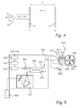
- Figure 5 illustrates one embodiment of the invention, having several resonators comprised in a work head.
- the pair of squares in the figure illustrate contacts, e.g. APC:s (angled physical contacts), for connecting one fiber end to another.
- the system comprises a power source, to power an SLED 200.
- the power source comprises a power supply unit 100 and a driver 101. Downstream of the light source or SLED, there is an optional optical isolator 300 and thereafter an optional beam splitter 350. The light emitted from the SLED is received by the isolator 300 before it is passed to the beam splitter on its way to the resonators 400.
- the resonators 400 are e.g. arranged as described in EP 1 849 556
- optical fibres 410 are permanently arranged in the work head 600, and each arranged with a contact 412, e.g. an APC contact, such that the light from the light source 200 is easily connected to a particular resonator 400 by means of feeding light from the beam splitter 350 to the corresponding optical fibre contact 412 of the work-head 600.
- the system may also comprise an optional reference resonator 500, e.g.
- the reference resonator may be used for determining e.g. the stability of the system.
- the dashed lines indicate that the optical fibre 360 optically coupled to and the beam splitter 350 and the light source 200, may be connected to the reference resonator 500 and any of the work head resonators 400 one at a time. Alternatively, the light can be emitted into several resonators 400 at the same time, wherein the measuring system comprises means for separating the light emitted out of each cavity 400 such that it can be stored by the recording means as separate entities.
- a spectrograph or interferometer 700 e.g. a grating-based spectrograph using a CCD-array, preferably comprising storing means for saving a measured spectrum sample.
- the storing means may also be arranged in a separate processing unit.
- the sampling frequency of the interferometer 700 is one of the factors which determine the time span over which the instantaneous or momentary length of the resonator L is averaged. In other words the determined length of said resonator, L or L GEO , corresponds to a length as averaged during one sampling period.
- the saved spectrum is thereafter provided to computing means 800, e.g. a computer or a logical circuit, which determines the optical length of the resonator L based on the spectrum, according to the method described above.
- computing means 800 e.g. a computer or a logical circuit, which determines the optical length of the resonator L based on the spectrum, according to the method described above.
- computing means 800 e.g. a computer or a logical circuit, which determines the optical length of the resonator L based on the spectrum, according to the method described above.
- an Ocean Optic Spectrometer HR 4000 is used.
- the interference numbers above has been determined for a straight resonator having substantially parallel end surfaces.
- the interference numbers may be determined for any resonator, and thereafter the optical length of the resonator may be determined by the above described method. Thereafter the geometrical length may be computed.
- the wave guide is arranged in relation to the object surface, the distance to which is to be measured, such that resonating waves from the radiation source may be formed between the wave guide and the object surface; and a suitable a portion of the spectrum resulting from the resonating waves is recorded as discussed above - the method for determining a resonator length, or the distance between the wave guide and the object surface, as described herein, is not limited to any particular field of technology. In other words, the method and system described herein may be used as a general distance measuring sensor.
- a frequency swept laser may be used instead of an SLED
- a closed metallic wave guide may be used instead of the optical fibre
- wireless communication may be used for transmitting the digital spectrum to the analyzing unit.
Abstract
The invention provides a method and system for measuring the length of a reflective resonator, by analyzing an electromagnetic spectrum emitted therefrom. The emitted spectrum is used for estimating a first cavity length. This estimation is thereafter improved, by first computing at least one interference number for the spectrum, adjust this value to e.g. an integer or half-integer depending on the configuration of the resonator, and thereafter re-calculating the length of the resonator using the adjusted value of the interference number. The above is an efficient way of improving the accuracy in the determination of a physical property of a resonator.
Description
- The present invention relates to a method of determining the length of a resonator, an arrangement for determining the length of a resonator as well as a computer program for measuring the length of a resonator. The measurement is based on an analysis of a recorded electromagnetic spectrum received from said resonator.
- In recent year there has evolved a demand for in process high precision measurements. For many applications, the measuring process should preferably be fast, such that it can be used for continuous controlling of e.g. a milling machine or an EDM (electrical discharge machine).
- The above is illustrated by the following example. In an EDM, a chuck and a holder is normally used to clamp the work piece that is to be machined. The position accuracy in the plane of the chuck is normally about +/- 2 µm, and this is sufficient for most application. However, a major application area is manufacturing of electrodes for EDM:ing (Electrical Discharge Machining) and mould making by EDM:ing, as the last step. In recent years there has been an upcoming need for high precisions moulds, which are used for production of e.g. optical lenses with very high accuracy and very accurate micro parts. Further, there is also a need for extremely accurate machining of micro parts. The position accuracy for the coupling must then be on sub-micron level (e.g. +/- 0.2 µm). This is not possible to achieve with conventional couplings and especially not in the environment of an electrode and mould production process, as conventional system often are space needing and sensitive to traces of liquids, such as dielectricum and cooling liquids, fog, smoke, dust and particles from the process. Moreover, the sub-micron position of the holder is affected by the process forces and temperature gradients. Continuous position measurements with sub-micron accuracy are therefore preferably used.
- Further, the chuck is subjected to wear, which depends on the number of clampings, the process forces and particles from the process. The wear affects the position accuracy and must be monitored to replace the chuck in time before it has been worn down. Normally, the loss of accuracy due to wear is today measured in a separate process, often manual, in stead of at each clamping.
-
US 6 078 706 discloses a quasi-static fiber pressure sensor using self-referenced interferometry based on a broadband semiconductor source which probes the pressure plate deflection within a Fabry-Perot cavity where phase is demodulated with a dual grating spectrometer providing real-time, high resolution remote measurement of pressure using optical interrogation of a deflecting pressure plate. This technique yields absolute gap measurement in real time over a wide range of gap lengths with nanometre resolution. By tailoring the pressure plate design to cover the range of gaps and deflection that can be resolved, pressure sensing with psi resolution can be obtained in a kpsig pressure range. -
US 7 099 015 B2 describes a further fiber optic sensing device, which uses a Fabry-Perot cavity to sense a physical parameter. The cavity modulates the incident polychromatic light. The modulated light is recorded by an optical spectrometer means. The spectrum is analyzed in a signal processing unit which normalizes the spectrum and determines the phase of the modulated signal. The phase accumulated over whole range of wavelengths, has been used for identification of the physical parameter using a look-up-table. The cavity, the polychromatic light source and the spectroscope means are connected by fiber optic means. - Recently, an optical setup has been presented which enables position measurements with improved accuracy. The setup is described in
EP 1 849 556 -
EP 1 849 556DE 195 28 676 , which describes an optical system and a method of absolute distance measurements using two lasers of different frequencies. According to the measurement principle ofDE 195 28 676 an interferometer is used, wherein the light from one of the lasers is sent in one leg of the interferometer and reflected towards the object surface, the distance to which is to be determined. The light from the other laser is sent in the other leg of the interferometer and reflected towards a reference surface, the distance to which is known. The two reflected light beams are super positioned, and by continuously changing the frequency of one of the lasers a varying intermediate frequency is formed. This intermediate frequency contains all of the necessary phase information required for distance measurements. The periodic signals are proportional to the change in frequency of the laser, as well as to the path difference of the interferometer. - A disadvantage of the above described method is that the optical signals received from the reference object must be continuously compared to the signals from the reference interferometer in order to enable a determination of the distance to the object. Hence, an age variation in the reference interferometer may cause a change in the measurement results. Further, due to the rather large number of components the system is space consuming. Additionally, as the measurement result is partially determined by the path difference between the two legs of the interferometer, the device is sensitive to misalignments.
- The present invention provides new methods and arrangements for determining the length of a resonator having two end surfaces which reflects electromagnetic radiation. The drawbacks and limitations associated with the prior art are effectively eliminated or at least alleviated by a method, an arrangement and a computer program of the general kind set forth in the accompanying claims.
- The present invention has further advantages, which will be apparent from the detailed description as set forth below.
- It is a general object of the present invention to provide an improved method for determining the distance between two end surfaces in a resonator which is fast, may be implemented by means of basic algorithms and which may be performed without the use of a reference interferometer.
- According to a first aspect thereof, the invention relates to a method of determining the length of a resonator or cavity or interferometer comprising:
- providing a resonator or cavity or interferometer having a first and a second reflective end surface;
- transmitting electromagnetic radiation in a waveguide, and emitting said radiation into said resonator or cavity or interferometer, wherein said radiation comprises at least one resonance wavelength;
- forming at least one resonant wave inside said resonator or cavity or interferometer by means of said radiation;
- transmitting a spectrum of said radiation, emitted out of said resonator or cavity or interferometer, in a waveguide to a recording unit;
- recording said emitted spectrum by said recording unit, and providing said recorded spectrum to an analyzing unit;
- determining, at said analyzing unit, at least one value of the resonator or cavity or interferometer length using said recorded spectrum;
- selecting, at said analyzing unit, at least one mark wavelength of said spectrum by determining a maximum, a minimum or an inflexion point of said recorded spectrum;
- computing an estimated interference number, based on a ratio of said at least one value of the resonator or cavity or interferometer length and said working wavelength;
- determining an actual interference number as the closest possible interference number to said estimated interference number;
- computing a second value of the resonator or cavity or interferometer length based on a product of said second interference number and said working wavelength.
- It is to be noted that the measures or steps described above may be executed in any suitable order, as long as the desired result is achieved.
- This method has the advantage of representing a fast and efficient way to improve the accuracy or precision of a determination of the resonator length, by utilizing mathematical functions which are already available in high level programming languages. That it may be implemented with already available mathematical functions increases the ease of programming, an normally also the execution time of the program. Additionally, the method is fast as there are relatively few mathematical operation that are performed in order to determine the cavity length. For a centre wavelength of the light source equal to e.g. about 800 nm, the accuracy of the determination is preferably better than +/- 1 µm, more preferably better than +/- 0.5 µm, even more preferred better than +/- 100 nm, and most preferred better than +/- 50 nm. Further, as it is independent of a continuous measurement of a reference interferometer, the accuracy of the measurement is not dependent on the condition of the reference interferometer. Additionally, according to most instances of the method it is also advantageous in that it provides an absolute measurement of the cavity length. I.e. there is normally no need for a reference surface, or a moving surface in order to be able to determine the length of the cavity. Instead for most applications the information contained in one spectrum emitted from the resonator is sufficient in order to determine the length of the cavity with sufficient accuracy. Further, the method is also advantageous as it allows a measurement of the cavity length, also when the cavity has a low visibility.
- According to a second aspect thereof, the invention relates to a system for determining the length of a resonator, which system comprises:
- a resonator;
- a first set of radiation transmitting means arranged to transmit electromagnetic radiation to said resonator;
- recording means operative to record an electromagnetic spectrum;
- a second set of radiation transmitting means arranged to transmit radiation from said resonator to said recording means; and
- analyzer operative to determine a length of said resonator by:
- determining at least one value of the resonator length using said recorded spectrum;
- selecting at least one mark wavelength of said spectrum by estimating a maxima, minima or an inflexion point of said recorded spectrum;
- computing an estimated interference number, based on a ratio of said at least one value of the resonator length and said working wavelength;
- determining an actual interference number as the closest possible interference number (I) to said estimated interference number;
- computing a second value of the resonator length based on a product of said second interference number and said working wavelength.
- According to a third aspect thereof, the invention relates to a computer program comprising computer program instructions to program a programmable processing apparatus to become operable to perform a method comprising the steps of:
- receiving a recorded electromagnetic spectrum modified by a resonator;
- determining at least one value of the resonator length using said recorded spectrum;
- selecting a mark wavelength of said spectrum by determining a maxima, minima or an inflexion point of said recorded spectrum;
- computing an estimated interference number, based on a ratio of said at least one value of the resonator length and said mark wavelength;
- determining an actual interference number as the closest possible interference number to said estimated interference number;
- computing a second value of the resonator length using a product of said second interference number and said mark wavelength.
- Both said second and third aspect of the invention involves the same advantages as were discussed in relation to said first aspect thereof. Additionally, as the length of the cavity is determined by the emitted spectrum, the system is less sensitive to misalignments due e.g. to harsh environmental conditions and rough handling, compared to the prior art discussed above.
- Basically, the invention provides a method, system and computer program for determining or measuring the length of a reflective resonator, by analyzing an electromagnetic spectrum emitted therefrom. The emitted spectrum is used for estimating a first cavity length. This estimation is thereafter improved, by first computing at least one interference number for the spectrum, adjust this value to a possible interference number e.g. a integer or half-integer depending on the configuration of the resonator, and thereafter re-calculating the length of the resonator using the adjusted or corrected value of the interference number. The above steps provide an efficient way of improving the accuracy in the determination of a physical property of a resonator.
- The method and system may for e.g. be used to determine the length of many types of resonators or interferometers, such as e.g. Fabry-Perot interferometers, Fizeau interferometers, Gires-Tournois etalons, Michelson interferometers, circular resonators etc.
- In relation to this invention the term radiation emitting means refers to any radiation source capable of emitting electromagnetic radiation having a suitable wavelength range. According to one embodiment, said radiation source is a light source which emits radiation in one or more spectra selected from a group comprising the visible spectra, the near infrared spectra, the infrared spectra, the near UV-spectra, the UV-spectra, the X-ray spectra and the microwave-spectra. In other words said electromagnetic radiation may be radiation in the optical domain or light or visible light.
- In relation to this invention the term resonator refers to an arrangement comprising two end surfaces, between which standing waves or resonant waves may form. I.e. at least one of the surfaces must reflect at least a portion of the incident radiation. The optical path of the resonator may be straight or bent. A resonator having a bent optical path preferably comprises reflective means for forwarding the radiation. The walls of a resonator having a straight optical path are preferably substantially parallel. In other words, the inclination of one surface as compared to the other is less than 10°, preferably less than 5°, even more preferred less than 3°, still more preferred less than 1° and most preferred less than 0.5°. The resonator may be open or closed. The difference between an open or closed resonator is that the closed resonator has one or several walls arranged between said side surfaces. According to one embodiment of the invention said resonator comprises two reflecting, substantially parallel walls for forming standing waves of said radiation inside said resonator. According to one example said resonator is a Fabry-Perot cavity, and preferably an asymmetric Fabry-Perot cavity. In an asymmetric Fabry-Perot cavity, there is a substantial difference in reflectivity between of the respective endwalls of the resonator. In this document the words resonator, cavity and interferometer are used interchangeably.
- In relation to this invention the term band width refers to a wavelength or frequency interval, either as continuously emitted, from e.g. a LED, or as emitted over time, from e.g. a tunable laser. Through out this description band width and tunable range is used interchangeably.
- In relation to this invention the term interference number, I, is e.g. I=2L/λR and determines the order of the resonant wave. For each resonator there is a fundamental frequency, which corresponds to the standing wave having the lowest frequency, and overtones which are multiples of the fundamental frequency. For each resonator there are predetermined values which the interference number may assume, these values are also referred to as possible interference numbers. For a two-wall cavity or resonator where the radiation is emitted in at one of the end-walls, there are generally two types of resonances, a first type where the resonating waves fulfils the expression λR1=2L/N, N=1,2,3...; and a second type where the resonating waves fulfils the expression λR2=4L/(2N-1), N=1,2,3.... In other words, for a resonator of the first type the possible interference numbers equals I=2L/λR1=N=1,2,3, i.e. any positive integer value. For a resonator of the second type the possible interference numbers equals I=2L/λR2=(2N-1)/2=0.5, 1.5, 2.5, i.e. any positive half-integer value. The fundamental frequency has the lowest interference number, the first overtone has the second lowest interference number etc. When a wavelength or frequency spectrum of the resonator is analysed, normally only a portion of the resonant wavelengths or resonant frequencies are distinguishable at the centre of the spectrum. Despite this an estimation of the interference number for a certain local maximum or minimum point, may be computed using e.g. 2L/λR, depending on the configuration of the cavity, and thereafter adjust this value to the closest possible interference number. The group of possible interference numbers may be determined theoretically, based on the configuration of the resonator and the radiation source. Alternatively, the skilled man may determine the possible interference numbers of a certain resonator by e.g. emitting radiation having a well known wavelength with a very narrow band width into the resonator and analyzing the intensity of the radiation emitted therefrom, for at least a portion of the wavelength range of the light source, which light source is later used at the length determination. The intensity emitted therefrom may also be analysed through out the whole bandwidth of the light source, which is to be used at the length determination.
- If two consecutive interference wavelengths λ1 and λ2 have been obtained, following equation system can be used for estimating the resonator length L

where I is the interference number, n the refractive index inside the cavity, and L the optical length of the cavity or resonator. - In relation to this invention the term possible interference number, relate to the interference numbers which can be assumed for a certain cavity. As explained above the group of possible interference numbers for a certain cavity is defined by the cavity design or the properties of the cavity, such as selected materials for the cavity walls and their reflectivity as well as the refractive index inside said cavity. More specifically, the group of possible interference numbers may be determined by the properties of the cavity in combination with the properties of the light source, such as band width and coupling into the cavity.
- In relation to this invention the term wave guide refers to a device, which is capable of transmitting radiation emitted from the radiation source to the resonator. Waveguides used at optical frequencies are preferably dielectric waveguides, i.e. structures in which a dielectric material with high permittivity, and thus high index of refraction, is surrounded by a material with lower permittivity. This structure guides optical waves by total internal reflection. The most common optical waveguide is an optical fibre. Other types of optical waveguide include photonic-crystal fibre, which guides waves by any of several distinct mechanisms. Further guides in the form of a hollow tube with a highly reflective inner surface, which may be of polished metal or may be covered with a multilayer film that guides light by Bragg reflection, may also be used. One can also use small prisms around the pipe which reflect light via total internal reflection. The end of the wave guide may be arranged in the wall of the resonator. If an optical fibre is used it may be grind at the same time as the resonator wall, such that a substantially flat surface is achieved.
- In relation to this invention length L normally refers to the optical length or e.g. a resonator for a certain wavelength. In order to convert this value to the geometrical length following expression may be used: L(λ) = LGEO*n(λ), wherein L is the optical path length, LGEO the corresponding geometrical length and n the refractive index inside the resonator as dependent on wavelength. Based on the length or the geometrical length of the resonator, further properties or physical parameters of the system may be determined such as a pressure force or strain acting on the resonator, the temperature of the resonator, the refractive index inside the resonator.
- In relation to this invention the term spectrometer refers to any device which is capable of converting an electromagnetic spectrum to a digital one, such that the intensity of the radiation as dependent on the frequency and/or wave length may be determined. The spectrometer may comprise storing means for holding the digital spectrum. The spectrometer may e.g. be a grating-based spectrometer e.g. equipped with a CCD-detector, but many other types of spectrometers are possible. When converting the optical spectrum to a digital one, the spectrometer normally has a predetermined sample rate during which light is recorded. In other words, the digital spectrum of the spectrometer is normally an averaged spectrum from the light source, which is averaged over one sample interval.
- Advantageously, the spectrum received from the resonator is normalized, preferably by comparing it to a reference spectrum, even more preferred by comparing it to a reference spectrum of said radiation source, and most preferred by subtracting said reference spectrum from said resonator spectrum Sr. This is advantageous as it enables a more accurate measurement result to be achieved, as some wavelength dependent variations of the radiation source may be compensated for. The smaller the difference between the refractive index inside the resonator and the index of the reflecting resonator wall, the more important to clear the spectrum from e.g. noise and disturbances, e.g. by use of a reference spectrum according to known method, in order achieve a more accurate result of the determination.
- Preferably, the recorded spectrum from said resonator is Fourier transformed before the length of the resonator is determined. This is advantageous as it increases the accuracy of the determination. Optionally, the determination of said resonator length comprises the step of determining the centre of location of the resonant part, i.e. a pulse, of said transformed spectrum. The use of a function for determining the centre of location of the resonant part is advantageous as it normally is a stable method, which is available as a standard function.
- According to one embodiment, the recorded spectrum from the resonator is first provided in the frequency domain, before said Fourier transform is preformed. This is advantageous as it increases the accuracy of the determination. Further, window functions e.g. Hanning, Hamming, Blackman and zero-padding techniques may be used to further improve the accuracy of the determination.
- The band width of said radiation is preferably chosen such that that the recorded spectrum comprises at least two interference minima or at least two interference maxima, even more preferred the interference spectrum comprises at least five interference minima or at least five interference maxima. This is advantageous as improves the accuracy of the determination of the cavity length.
- According to one embodiment a first and a second mark wavelength are selected by determining a mark wavelength for one maximum and one minimum, or for two different maxima or two different minima of said spectrum. This is advantageous as it improves the accuracy of the determination of the cavity length. Moreover, a respective interference number is determined using e.g. a ratio of said value of the cavity length and said first or second mark wavelength. Alternatively, only a first interference number corresponding to said first mark wavelength is computed, and said second interference number is determined based on the relation between the mark wavelengths, i.e. the number of maxima or minima present in the spectrum between said first mark wavelength and said second wavelength. According to one embodiment a second resonator length is computed by performing the same steps for said second mark wavelength as were described for the mark wavelength in relation to the independent claims.
- When the interference number is calculated, one may distinguish between the cases where the index in the cavity is known to be higher or lower compared to the index of the optical fibre and when the index is completely unknown. In the former case, the algorithm or method may be arranged to to chose an interference number from a pre-selected list of possible interference numbers, e.g. 1,2,3... or 0.5,1.5,2.5..., corresponding to the known interference number. In the latter case, the algorithm or method may be arranged to choose both list and interference number.
- According to one example a polychromatic light source is used, i.e. the radiation source is operative to emit polychromatic light. Examples of such light sources are: a halogen lamp, a LED, an SLED or a tuneable laser. Depending on the length of the cavity, radiation sources based on radio frequencies, micro-wave signals and X-ray might also be used. The light source is preferably selected such that

- According to one example said light source is a swept light source, such as a tuneable laser. Preferably, said wave guide is an optical fibre, as an optical fibre normally is stable also in harsh environments.
- According to one embodiment said recording unit comprises spectrometer means for determine the intensity of the radiation at different wave-lengths. Advantageously, the wavelength band of the recorded spectrum is

where Δλ is the bandwidth of the recorded spectrum, λc is the centre wavelength of the recorded spectrum and L the optical length of the resonator. - According to one example the resonator is formed by a first and a second surface of a work-head unit, and said work-head unit preferably comprises a first and a second part, which are separable, wherein said first surface is a surface of said first part and said second surface is a surface of said second part. The first and a second part may for example be a chuck and a work piece holder for insertion in said chuck, respectively, as is discussed in
EP 1 849 556 - According to one example the resonator is an optical resonator, i.e. resonant light waves may be formed inside the resonator.
- The medium inside the resonator may be a solid such as glass or plastic, gas or liquid or a combination of these, the medium may also comprise small particles. In other words, according to one embodiment the resonator is arranged to contain a fluid. More specifically the medium in the resonator may be cutting fluid as discussed in
EP 1 849 556 - Flushing may be preformed through the holes having the reference numeral 11 in
EP 1 849 556 - One general way of calibrating a system, method or program according to the invention is by replacing one or several of the resonators which are normally used with a master resonator, having a known accurately determined length. The length of the master resonator is determined using the method according to the invention. Thereafter, the parameters of the measuring system are adjusted, e.g. calibration factors may be adjusted, such that the computed length of the master resonator corresponds to the previously determined length thereof. Calibration may be needed due to wear of the resonator, or because a property of the resonator has been changed. According to one example each time the cutting liquid used in the machine is changed from a first cutting liquid to a second cutting liquid, the master resonator is provided with the second cutting liquid, the length of the master resonator is determined and a calibration parameter is adjusted if needed.
- Basically, for a given resonator and its resulting electromagnetic spectrum, the interference numbers may only assume certain values as is explained in more detail below. In essence, the invention is based on the realisation that this nature of the interference numbers may be used, for improving the accuracy of an interference number dependent parameter, e.g. LEST. Thus, by using an estimation of a first parameter, e.g. LEST, for computing an interference number, IEST, replacing the calculated interference number with the closest one in a series of known or predetermined interference numbers ICORR, and thereafter re-calculating said first parameter, e.g. LEST, using the new interference number, ICORR, - the accuracy of the determination of said first parameter, LEST, may be improved.
- These and other aspects of the invention will be apparent from and elucidated with reference to the embodiment(s) described hereinafter.
- In the following detailed description, reference is made to the drawings, on which:
-
Figure 1 schematically illustrates one example of a resonator according to the invention; -
Figure 2a schematically illustrates one example of a wavelength spectrum from said resonator; -
Figure 2b schematically illustrates the corresponding frequency spectrum to the wavelength spectrum shownfigure 2a ; -
Figure 2c schematically illustrates the resulting spectrum after a Fourier transform has been performed of the wavelength spectrum shown inFigure 2a ; -
Figure 3 is a block diagram illustrating one example of steps to be performed in order to determine the length of the resonator; -
Figure 4 schematically illustrates a resonator, wherein the light is fed by means of an optical fibre; and -
Figure 5 schematically illustrates an optical setup for determining the distances between several pair of surfaces in a work head. -
Figure 1 illustrates one example of a resonator, the length of which may be measured with the method described herein. Light λLS is emitted into aresonator 10 having, at least momentary, a length LGEO, wherein said light has a first spectral distribution SLS. The resonator illustrated inFigure 1 comprises of afirst medium 1, having a first refractive index n1, arranged between a first andsecond end wall 2,3. In other words, the resonator has twosurfaces Figure 2a . According to this example the radiation is emitted from the resonator in a direction parallel with the direction by which it was emitted into the resonator. In other words the radiation is emitted into and out of the resonator at different walls, an in this example in two opposing wall, i.e. two walls arranged opposite each other.(2). - The second spectral distribution of the radiation emitted out of said resonator comprises peaks at wavelengths corresponding to resonating wavelengths of said resonator. The resonating wavelengths of the resonator are determined by the optical length of the resonator L between said end surfaces.
- For this type of resonator or cavity the interference number is described by the following table:

- In the table above Metal means that the
respective end surface respective end surface - According to one example the
medium 1 inside said cavity is air (n1 = 1.0) and the end surfaces 3, 4 are made of highly reflecting metal. In this case the resonating wavelengths λR=2L/N, N = 1, 2, 3..., and the interference number or possible interference number I=2L/λR= N = 1, 2, 3.... i.e. an integer value. - According to another example the medium inside the cavity is glass e.g. flint glass (n1 > 1.52) and one of the end surfaces is made of reflecting metal and the other of crown glass (n = 1.52). In this case the resonation wavelengths λR=4L/(2N-1), N = 1, 2, 3..., and the interference number I=2L/λR= (2N-1)/2 = 0.5, 1.5, 2.5..., i.e. a half integer value.
- According to yet another example, the resonator is a symmetric Fabry-Perot, i.e. r1=r2, and the transmitted signal can be expressed as:

where r1 2 =r2 2=R, and r1, r2 are the reflectivities for the first and second surface respectively, L the cavity length and λ the wavelength. In this case, only the diagonal cells in Table 1 are of importance and hence the interference numbers are always of integer type. - According to one method a first step a group of possible interference numbers is determined, e.g. defined by the expression N or (2N-1)/2, depending on the properties of the cavity. Thereafter, a first estimation of the interference number is determined LEST, which is later rounded off to the closest value contained in said group of possible interference numbers.
- The radiation spectrum emitted from the resonator is transmitted to and recorded by recording means. The spectrum is preferably transmitted by means of a wave guide. A first estimation of the cavity length LEST is determined, e.g. by providing a stored value or by computing it from the stored spectrum using a known method. According to one example the estimation is computed by localising fundamental frequency of the interference spectrum. This may be done by performing a Fourier transform of the stored spectrum either in the wavelength or the frequency domain. Normally, it is preferred to perform the Fourier transform in the frequency domain of the spectrum as this generally gives a better accuracy.
Figure 2b illustrates the spectrum in the frequency domain SR(f), and a Fourier transform of this spectrum is found inFigure 2c . In the Fourier spectrum one can identify two pulses, the left most of these is the DC-contribution of the light source, the other corresponds to the fundamental frequency fR of the spectrum. The resonance frequency fR may be determined by using mathematical function which identifies the centre of location of the peak. In order to improve the accuracy of the mathematical functions, window functions can be used to prepare the spectrum. According to one example zero-padding techniques are used. Preferably, the Fourier transformed spectrum comprises at least 5 fringes, i.e. for a resonator length of 20-100 µm the band width of the radiation source is preferably about 50-100 nm, depending on the desired number of fringes. -
Figure 3 illustrates an example of the steps, which may be performed in order to determine the length of the resonator. In a first step Ia a recorded wavelength spectrum SR, and a first estimation of the cavity length LEST is provided to an analyzing unit. In another step Ib the number of different mark wavelengths j that are to be selected is determined, and the current number is set to i=1. In a second step II a first mark wavelength λM1 corresponding to a resonation wavelength of said spectrum is selected or determined. Generally, the greater number of mark wavelengths j that are selected and used of computing the length of the resonator, the more accurate the result. λMi may be determined by identifying the position of a turning point or a local maximum or minimum of SR using either the wavelength or the frequency domain. Alternatively, LEST may be used to compute an approximation of λM, which indicates the approximate location for the inflexion point. When an approximation of λM has been determined, an algorithm involving parabolic curve fitting may be used to determine the maximum or minimum of the curve. - Thereafter, in a third step III a first estimation of the interference number IEST is determined by computing the ratio between e.g. 2*L / λM and, in step IV, the value of IEST is rounded off or set to the closest possible interference number, as defined by the predetermined properties of the resonator and in accordance with the table above. In other words, first the possible interference numbers are determined or a group of possible interference numbers is provided, e.g. based on the properties of the resonator, and thereafter the first interference number IEST is rounded off to the closest one of these interference numbers. According to another example, the refractive index of the medium (1) inside the cavity is unknown. In this case all possible interference numbers (corresponding to the current resonator but independent on refractive index) is determined, i.e. corresponding to a group comprising e.g. both half integer and integers. Provided that the estimated interference number is considerably closer to one of a half integer and an integer, the interference number IEST is rounded off or set to the closest one of those. E.g. for an estimated interference number, which differ from the closest integer or half-integer by less than e.g. 0.2, the correct interference number ICORR may be determined by rounding off said interference number to the closest one of the integer and the half-integer. In other words, there are instances for which the improved interference number ICORR can be identified, without any previous knowledge of the properties of the resonator. In step V, a more accurate or correct value of the cavity length LCORR is computed by determining the product of ICORR*λM/2, in other words by determining ICORR* λM/2.
- Above, in step V the equations IEST = 2*L / λM (= b*L/λM) and LCORR = ICORR*λM /2 (= ICORR*λM/b) are used. According to one embodiment, as b is used in both equations, b may be set to have any value, except 0, as long as the same value is used for computing LCORR, as was used for computing IEST; and as long as the possible interference numbers are adjusted accordingly. For example, b=1 and I = N/b = 1/b, 2/b, 3/b ..., or I = N/(2*b) = 1/(2*b), 2/(2*b), 3/(2*b) ..., and IEST is set to one off these values. I.e. for determining the interference number it is sufficient to compute a ratio of LEST / λM = IEST', choose the closest ICORR'-value, from a group comprising e.g. 0.5, 1, 1.5, 2... or 0.25, 0.5, 0.75, 1 depending on the configuration of the resonator, and calculate the product of ICORR'*λM = LCORR.
- According to one embodiment the number of mark wavelengths to be selected is set to three j=3, and three consecutive maxima or minima of the spectrum are determined λM1, λM2, λM3. For each of these wavelengths a corresponding vale of IESTi is determined, using the relation IESTi =2*LEST / λMi, i= 1,2,3. For each value of IESTi a value of ICORRi, and LCORRi is determined as described above. Thereafter, a mean value of LCORR is computed based on LCORRi, with due adjustment for the variation of the refractive index with different wave-lengths. According to one example, LGEOi = n*λMi is computed for each λMi, thereafter a mean value for LGEO is computed based on LGEOi.
- Alternatively, only one value of IEST and ICORR is computed. Thereafter e.g. two more values of ICORR are determined based on the knowledge of the properties of the resonator. In other words, if ICORR1 = 34, ICORR2 and ICORR3 are taken to be 33 and 35, respectively. Thereafter, the inflexion points in SR corresponding to λM2 and λM3 is determined. Finally, LCORRi is determined based on ICORRi*λMi/2 i= 1,2,3 and a mean value of L is computed as described above.
- According to another example the resonator is arranged as described above, with the exception that the light is emitted into and out of the resonator at the same
reflective surface 1. The length of the resonator is determined in the same way as was described above. Please note, that changing the position of the exit surface for the radiation with respect to the entrance surface in most cases results in a different set of possible interference numbers. -
Figure 4 is a schematic illustration of one example of a resonator, arranged as described in relation toFigure 1 , with the exception that theentrance surface 4 for the radiation into the cavity, is the same as theexit surface 4. According to a specific example the resonator comprises afirst end surface 4, wherein anoptical fibre 10 is arranged, and asecond end surface 5 of metal. Thefirst end surface 4 is the interface between air (n=1) in the resonator and the optical fibre (n=1.46), the reflectivity for this surface is expressed r1. The second end surface is the interface between the air in the resonator and a metal surface, r2. Light travelling inside the interferometer is non-collimated since the light injected into the interferometer origins from a plane fibre-facet with NA=0.13. The distance between said first and second end interfaces represent the length of the resonator L. - For a cavity having this configuration the possible interference numbers are positive integers when the refractive index is greater than the refractive index of the optical fiber, and positive half integers as when the refractive index is lower than the refractive index of the optical fiber.
- For this example the reflected field strength corresponds to:

where L is the optical length of the resonator, r1 and r2 are the reflectivities as explained above, λ is the wavelength at which the optical length is determined. This corresponds to a reflected intensity corresponding to:
From this equation an estimation of e.g. the length of the cavity LEST may be computed. - The above expression corresponds to a modulation depth of:

From equation (5) it can be proven that provided that r2 is larger than 1/√3 ≈ 0.58, a maximum modulation depth is obtained, independent of the value of r1 . However, the method may be used even if the modulation depth is not maximised. - According to one embodiment the resonator in a work head, which comprises two walls (4,5), the distance between which is adjustable, e.g. by applying an increased direct or indirect pressure to one of the surfaces by means of a processing tool. Said walls are preferably substantially parallel and made of a reflective material. By measuring the instantaneous distance between the surfaces, the pressuring force of the tool may be determined. The optical waveguide is e.g. an optical fibre, the end of which is provided in one of the end surfaces, preferably substantially in the same plane as the reflecting wall surface inside the resonator. In other words, in this arrangement the surface of the optical fibre is comprised in one of the resonator walls and is one of the surfaces against which the light is reflected. In yet other words, the end surface of the resonator may comprise two or more different material such as, in this case, metal and glass. In this embodiment the optical fibre is preferably used both for transmitting light from the light source to the resonator, and for transmitting light or the modified spectrum from the resonator to the recording means.
-
Figure 5 illustrates one embodiment of the invention, having several resonators comprised in a work head. The pair of squares in the figure illustrate contacts, e.g. APC:s (angled physical contacts), for connecting one fiber end to another. The system comprises a power source, to power anSLED 200. The power source comprises apower supply unit 100 and adriver 101. Downstream of the light source or SLED, there is an optionaloptical isolator 300 and thereafter anoptional beam splitter 350. The light emitted from the SLED is received by theisolator 300 before it is passed to the beam splitter on its way to theresonators 400. Onelight path 370 from thebeam splitter 350 is led to theresonators 400, and the other 380 is preferably absorbed or transmitted out of the system, such that reflection from the second path do not interfere with the measurements. Theresonators 400 are e.g. arranged as described inEP 1 849 556optical fibres 410 are permanently arranged in thework head 600, and each arranged with acontact 412, e.g. an APC contact, such that the light from thelight source 200 is easily connected to aparticular resonator 400 by means of feeding light from thebeam splitter 350 to the correspondingoptical fibre contact 412 of the work-head 600. The system may also comprise anoptional reference resonator 500, e.g. an ultra stable Fabry-Perot cavity, for calibration or verification of the system. The reference resonator may be used for determining e.g. the stability of the system. The dashed lines indicate that theoptical fibre 360 optically coupled to and thebeam splitter 350 and thelight source 200, may be connected to thereference resonator 500 and any of thework head resonators 400 one at a time. Alternatively, the light can be emitted intoseveral resonators 400 at the same time, wherein the measuring system comprises means for separating the light emitted out of eachcavity 400 such that it can be stored by the recording means as separate entities. - After the light has been reflected within a
resonator 400 of thework head 600, it is returned to via theoptical fibre beam splitter 350 and thereafter to a spectrograph orinterferometer 700, e.g. a grating-based spectrograph using a CCD-array, preferably comprising storing means for saving a measured spectrum sample. The storing means may also be arranged in a separate processing unit. The sampling frequency of theinterferometer 700 is one of the factors which determine the time span over which the instantaneous or momentary length of the resonator L is averaged. In other words the determined length of said resonator, L or LGEO, corresponds to a length as averaged during one sampling period. - The saved spectrum is thereafter provided to computing means 800, e.g. a computer or a logical circuit, which determines the optical length of the resonator L based on the spectrum, according to the method described above. According to one example an Ocean Optic Spectrometer HR 4000 is used.
- Although, the interference numbers above has been determined for a straight resonator having substantially parallel end surfaces. The interference numbers may be determined for any resonator, and thereafter the optical length of the resonator may be determined by the above described method. Thereafter the geometrical length may be computed.
- Even if the measuring principle is partly described with reference to milling machines etc, it is to be understood that as long as a suitable radiation source is selected; the wave guide is arranged in relation to the object surface, the distance to which is to be measured, such that resonating waves from the radiation source may be formed between the wave guide and the object surface; and a suitable a portion of the spectrum resulting from the resonating waves is recorded as discussed above - the method for determining a resonator length, or the distance between the wave guide and the object surface, as described herein, is not limited to any particular field of technology. In other words, the method and system described herein may be used as a general distance measuring sensor.
- A person skilled in the art will given the above described conditions be able to select a suitable radiation source, interferometer and recording means or recorder. He also realizes that the present invention by no means is limited to the preferred embodiments described above. On the contrary, many modifications and variations are possible within the scope of the appended claims. For example, a frequency swept laser may be used instead of an SLED, a closed metallic wave guide may be used instead of the optical fibre, wireless communication may be used for transmitting the digital spectrum to the analyzing unit.
- In the claims, the word "comprising" does not exclude other elements or steps, and the indefinite article "a" or "an" does not exclude a plurality. A single processor or other unit may fulfill the functions of several items recited in the claims. The mere fact that certain measures are recited in mutually different dependent claims does not indicate that a combination of these measured cannot be used to advantage. A computer program may be stored and/or distributed on a suitable medium, such as an optical storage medium or a solid-state medium supplied together with or as part of other hardware, but may also be distributed in other forms, such as via the Internet or other wired or wireless telecommunication systems. Any reference signs in the claims should not be construed as limiting the scope.
Claims (14)
- A method of determining the length (L) of a resonator (1) comprising:- providing a resonator having a first and a second reflective end surface (4,5);- transmitting electromagnetic radiation (λLS) in a waveguide, and emitting said radiation into said resonator, wherein said radiation comprises at least one resonance wavelength;- forming at least one resonant wave inside said resonator by means of said radiation (λLS);- transmitting a spectrum of said radiation (SR), emitted out of said resonator, in a waveguide to a recording unit (700, 800);- recording said emitted spectrum (SR) by said recording unit, and providing said recorded spectrum to an analyzing unit;- determining, at said analyzing unit, at least one value of the resonator length (L) using said recorded spectrum;- selecting, at said analyzing unit, at least one mark wavelength (λM) of said spectrum by determining a maximum, a minimum or an inflexion point of said recorded spectrum;- computing an estimated interference number (IEST), based on a ratio (LEST/λM) of said at least one value of the resonator length (LEST) and said working wavelength (λM);- determining an actual interference number (ICORR) as the closest possible interference number (I) to said estimated interference number (IEST);- computing a second value of the resonator length (LCORR) based on a product (IEST*λM) of said second interference number (IEST) and said working wavelength (λM).
- A method according to any one the preceding claims, further comprising:- receiving said radiation from a radiation source, before said radiation is transmitted and emitted into said resonator; and- normalizing said recorded wavelength spectrum by comparing it to a reference spectrum, and preferably to a reference spectrum of said radiation source.
- A method according to any one of the preceding claims, wherein said determining of at least one value of the resonator length (L) further comprises performing a Fourier transform of at least a portion of said recorded spectrum before said resonator length is determined, and wherein said determining of said resonator length preferably comprises determining the centre of location of the resonant part.
- A method according to claim 3, wherein said determining of at least one value of the resonator length (L) further comprises converting at least a portion of said wavelength spectrum to the frequency domain, before said Fourier transform is performed.
- A method according to any one of the preceding claims wherein the band with of said radiation (λLS) is chosen such that that said recorded spectrum comprises at least two interference minima or at least two interference maxima.
- A method according to any one of the preceding claims, wherein said selecting of at least one mark wavelength (λM) comprises selecting further mark wavelengths by determining further different maxima and/or a minima of said spectrum.
- A method according to any one of the preceding claims, wherein said determining of a second interference number (ICORR) further comprises providing a group of pre-determined possible interference numbers.
- A system for determining the length of a resonator (1, 400) comprising:- a resonator (1, 400);- a first set of radiation transmitting means (360, 410, 412) arranged to transmit electromagnetic radiation (λLS) to said resonator;- recording means operative to record an electromagnetic spectrum (SR);- a second set of radiation transmitting means arranged to transmit radiation from said resonator (1) to said recording means (700, 800); and- analyzer (800) operative to determine a length (L) of said resonator by:- determining at least one value of the resonator length (LEST) using said recorded spectrum;- selecting at least one mark wavelength (λM) of said spectrum by estimating a maxima, minima or an inflexion point of said recorded spectrum;- computing an estimated interference number (IEST), based on a ratio (LEST/λM) of said at least one value of the resonator length (LEST) and said working wavelength (λM);- determining an actual interference number (ICORR) as the closest possible interference number (I) to said estimated interference number (IEST);- computing a second value of the resonator length (LCORR) based on a product (IEST*λM) of said second interference number (IEST) and said working wavelength (λM).
- A system according to claim 8, wherein the resonator is formed by a first and a second surface of a work-head unit (600), wherein said work-head unit preferably comprises a first and a second part, which are separable, wherein said first surface is a surface of said first part and said second surface is a surface of said second part.
- A system according to claim 8 or 9, wherein said resonator comprises two reflecting, substantially parallel surfaces for forming resonating waves of said radiation.
- A system according to any one of claims 8-10, wherein said resonator is a resonator selected from a group comprising Fabry-Perot interferometers, Fizeau interferometers, Gires-Tournois etalons, Michelson interferometers and circular resonators.
- A system according to any one of claims 8-11, wherein said radiation transmitting means comprises a waveguide and preferably an optical fibre (360).
- A system according to any one of claims 8-12, wherein said resonator is arranged to contain a fluid.
- A computer program comprising computer program instructions to program a programmable processing apparatus to become operable to perform a method comprising:- receiving a recorded electromagnetic spectrum (SR) modified by a resonator (1);- determining at least one value of the resonator length (LEST) using said recorded spectrum;- selecting a mark wavelength (λM) of said spectrum by determining a maxima, minima or an inflexion point of said recorded spectrum;- computing an estimated interference number (IEST), based on a ratio (LEST/λM) of said at least one value of the resonator length (LEST) and said mark wavelength (λM);- determining an actual interference number (ICORR) as the closest possible interference number to said estimated interference number (IEST);- computing a second value of the resonator length using a product (IEST*λM) of said second interference number (IEST) and said mark wavelength (λM).
Priority Applications (6)
| Application Number | Priority Date | Filing Date | Title |
|---|---|---|---|
| EP08166344A EP2175228A1 (en) | 2008-10-10 | 2008-10-10 | Resonator length measurement |
| PCT/EP2009/063208 WO2010040838A1 (en) | 2008-10-10 | 2009-10-09 | Resonator length measurement |
| EP09783912.0A EP2335013B1 (en) | 2008-10-10 | 2009-10-09 | Resonator length measurement |
| JP2011530501A JP5538406B2 (en) | 2008-10-10 | 2009-10-09 | Cavity length measurement method |
| CN200980140143.XA CN102177409B (en) | 2008-10-10 | 2009-10-09 | Resonator length measurement |
| US13/121,043 US8134714B2 (en) | 2008-10-10 | 2009-10-09 | Resonator length measurement |
Applications Claiming Priority (1)
| Application Number | Priority Date | Filing Date | Title |
|---|---|---|---|
| EP08166344A EP2175228A1 (en) | 2008-10-10 | 2008-10-10 | Resonator length measurement |
Publications (1)
| Publication Number | Publication Date |
|---|---|
| EP2175228A1 true EP2175228A1 (en) | 2010-04-14 |
Family
ID=40301781
Family Applications (2)
| Application Number | Title | Priority Date | Filing Date |
|---|---|---|---|
| EP08166344A Withdrawn EP2175228A1 (en) | 2008-10-10 | 2008-10-10 | Resonator length measurement |
| EP09783912.0A Active EP2335013B1 (en) | 2008-10-10 | 2009-10-09 | Resonator length measurement |
Family Applications After (1)
| Application Number | Title | Priority Date | Filing Date |
|---|---|---|---|
| EP09783912.0A Active EP2335013B1 (en) | 2008-10-10 | 2009-10-09 | Resonator length measurement |
Country Status (5)
| Country | Link |
|---|---|
| US (1) | US8134714B2 (en) |
| EP (2) | EP2175228A1 (en) |
| JP (1) | JP5538406B2 (en) |
| CN (1) | CN102177409B (en) |
| WO (1) | WO2010040838A1 (en) |
Cited By (1)
| Publication number | Priority date | Publication date | Assignee | Title |
|---|---|---|---|---|
| WO2017144567A1 (en) * | 2016-02-23 | 2017-08-31 | Björn Habrich | Measuring a cavity by means of interference spectroscopy |
Families Citing this family (6)
| Publication number | Priority date | Publication date | Assignee | Title |
|---|---|---|---|---|
| CN102288103B (en) * | 2011-06-27 | 2013-07-03 | 清华大学 | Folding-fabry-perot-cavity-based cavity length measurement method and device |
| DE102015009595A1 (en) * | 2015-07-24 | 2017-01-26 | Universität Heidelberg | Method and apparatus for calibrating an optical resonator, use of the apparatus, use of an optical modulator and computer program product |
| NL2017595A (en) * | 2015-11-10 | 2017-05-26 | Asml Netherlands Bv | Proximity sensor, lithographic apparatus and device manufacturing method |
| CN106898942A (en) * | 2017-02-28 | 2017-06-27 | 中国科学院光电研究院 | The adjusting method of multi beam pulse phototiming |
| CN107961986A (en) * | 2017-11-22 | 2018-04-27 | 铜陵日兴电子有限公司 | A kind of unpowered high harmony resonator thickness category filter device |
| CN111122610B (en) * | 2019-11-22 | 2021-09-03 | 上海大学 | Active sensor based on half-integer order resonance mode |
Citations (6)
| Publication number | Priority date | Publication date | Assignee | Title |
|---|---|---|---|---|
| US4593368A (en) * | 1984-06-04 | 1986-06-03 | Kollmorgen Technologies Corporation | Technique for measuring very small spacings |
| DE19528676A1 (en) | 1995-08-04 | 1997-02-06 | Zeiss Carl Jena Gmbh | Interferometer arrangement for absolute distance measurement |
| WO2000017604A1 (en) * | 1998-09-22 | 2000-03-30 | The Government Of The United States Of America, As Represented By The Secretary Of The Navy | Quasi-static fiber pressure sensor |
| US7099015B2 (en) | 2003-08-25 | 2006-08-29 | Ivan Melnyk | Fiber optic sensing device for measuring a physical parameter |
| US20070086018A1 (en) * | 2005-10-14 | 2007-04-19 | Board Of Regents, The University Of Texas System | Broadband cavity spectrometer apparatus and method for determining the path length of an optical structure |
| EP1849556A1 (en) | 2006-04-27 | 2007-10-31 | System 3R International AB | Clamping apparatus with device for measuring the distance between a chuck and a worktool or workpiece holder |
Family Cites Families (14)
| Publication number | Priority date | Publication date | Assignee | Title |
|---|---|---|---|---|
| DE3044183A1 (en) * | 1980-11-24 | 1982-06-24 | Reinhard Dipl.-Phys. Dr. 7250 Leonberg Ulrich | METHOD FOR OPTICALLY MEASURING LENGTHS AND LENGTH CHANGES AND ARRANGEMENT FOR IMPLEMENTING THE METHOD |
| US5555089A (en) * | 1994-11-30 | 1996-09-10 | Anvik Corporation | Absolute distance measuring interferometry using multi-pass resonant cavity referenced to a stabilized laser source |
| JPH1183457A (en) * | 1997-09-12 | 1999-03-26 | Yazaki Corp | Spectral interference microscope and surface shape measuring method using it |
| US7057732B2 (en) * | 1999-01-25 | 2006-06-06 | Amnis Corporation | Imaging platform for nanoparticle detection applied to SPR biomolecular interaction analysis |
| US6449048B1 (en) * | 2000-05-11 | 2002-09-10 | Veeco Instruments, Inc. | Lateral-scanning interferometer with tilted optical axis |
| US6510256B1 (en) * | 2000-06-29 | 2003-01-21 | Proximion Fiber Optics Ab | Method and arrangement in connection with optical bragg-reflectors |
| CN1137369C (en) * | 2001-08-23 | 2004-02-04 | 四川大学 | Trackless large-part measuring device and method |
| US7483598B2 (en) * | 2004-03-15 | 2009-01-27 | Queen's University At Kingston | Phase shift optical loop spectroscopy |
| US7305158B2 (en) * | 2004-04-15 | 2007-12-04 | Davidson Instruments Inc. | Interferometric signal conditioner for measurement of absolute static displacements and dynamic displacements of a Fabry-Perot interferometer |
| EP1586854A3 (en) * | 2004-04-15 | 2006-02-08 | Davidson Instruments | Interferometric signal conditioner for measurement of the absolute length of gaps in a fiber optic Fabry-Pérot interferometer |
| JP4027352B2 (en) * | 2004-09-17 | 2007-12-26 | アンリツ株式会社 | Optical fiber probe device |
| TWI278682B (en) * | 2004-11-23 | 2007-04-11 | Ind Tech Res Inst | Fiber optic interferometric position sensor and measuring method thereof |
| EP1744119A1 (en) * | 2005-07-15 | 2007-01-17 | Proximion Fiber Systems AB | Swept-source optical coherence tomography |
| CN101126629A (en) * | 2007-09-25 | 2008-02-20 | 北京交通大学 | On-line measuring system using optical fiber grating synthetic wave for interfering step height |
-
2008
- 2008-10-10 EP EP08166344A patent/EP2175228A1/en not_active Withdrawn
-
2009
- 2009-10-09 JP JP2011530501A patent/JP5538406B2/en active Active
- 2009-10-09 CN CN200980140143.XA patent/CN102177409B/en active Active
- 2009-10-09 US US13/121,043 patent/US8134714B2/en not_active Expired - Fee Related
- 2009-10-09 EP EP09783912.0A patent/EP2335013B1/en active Active
- 2009-10-09 WO PCT/EP2009/063208 patent/WO2010040838A1/en active Application Filing
Patent Citations (7)
| Publication number | Priority date | Publication date | Assignee | Title |
|---|---|---|---|---|
| US4593368A (en) * | 1984-06-04 | 1986-06-03 | Kollmorgen Technologies Corporation | Technique for measuring very small spacings |
| DE19528676A1 (en) | 1995-08-04 | 1997-02-06 | Zeiss Carl Jena Gmbh | Interferometer arrangement for absolute distance measurement |
| WO2000017604A1 (en) * | 1998-09-22 | 2000-03-30 | The Government Of The United States Of America, As Represented By The Secretary Of The Navy | Quasi-static fiber pressure sensor |
| US6078706A (en) | 1998-09-22 | 2000-06-20 | The United States Of America As Represented By The Secretary Of The Navy | Quasi-static fiber pressure sensor |
| US7099015B2 (en) | 2003-08-25 | 2006-08-29 | Ivan Melnyk | Fiber optic sensing device for measuring a physical parameter |
| US20070086018A1 (en) * | 2005-10-14 | 2007-04-19 | Board Of Regents, The University Of Texas System | Broadband cavity spectrometer apparatus and method for determining the path length of an optical structure |
| EP1849556A1 (en) | 2006-04-27 | 2007-10-31 | System 3R International AB | Clamping apparatus with device for measuring the distance between a chuck and a worktool or workpiece holder |
Non-Patent Citations (1)
| Title |
|---|
| EGOROV S A ET AL: "Spectral signal processing in intrinsic interferometric sensors based on birefringent polarization-maintaining optical fibers", JOURNAL OF LIGHTWAVE TECHNOLOGY USA, vol. 13, no. 7, July 1995 (1995-07-01), pages 1231 - 1236, XP002515162, ISSN: 0733-8724 * |
Cited By (2)
| Publication number | Priority date | Publication date | Assignee | Title |
|---|---|---|---|---|
| WO2017144567A1 (en) * | 2016-02-23 | 2017-08-31 | Björn Habrich | Measuring a cavity by means of interference spectroscopy |
| US10627210B2 (en) | 2016-02-23 | 2020-04-21 | Björn Habrich | Measuring a cavity by means of interference spectroscopy |
Also Published As
| Publication number | Publication date |
|---|---|
| EP2335013A1 (en) | 2011-06-22 |
| JP2012505393A (en) | 2012-03-01 |
| US20110176143A1 (en) | 2011-07-21 |
| CN102177409B (en) | 2014-03-26 |
| US8134714B2 (en) | 2012-03-13 |
| JP5538406B2 (en) | 2014-07-02 |
| CN102177409A (en) | 2011-09-07 |
| WO2010040838A1 (en) | 2010-04-15 |
| EP2335013B1 (en) | 2014-04-23 |
Similar Documents
| Publication | Publication Date | Title |
|---|---|---|
| EP2335013B1 (en) | Resonator length measurement | |
| US6778307B2 (en) | Method and system for performing swept-wavelength measurements within an optical system | |
| EP1586867B1 (en) | Method and apparatus for continuous readout and fabry-perot fiber optic sensor | |
| US7679750B2 (en) | Cavity ring-down apparatus and method for measuring reflectivity of highly reflective mirrors | |
| US11346770B2 (en) | Optical fiber sensor for salinity and temperature measurement | |
| CN101762566B (en) | Optical crystal microcavity defect mode gas sensing method | |
| JP2008180736A (en) | Method and apparatus for measuring optical and physical thickness of optically transparent target | |
| US7271916B2 (en) | Characterization of optical fiber using Fourier domain optical coherence tomography | |
| US8154715B2 (en) | Method for monitoring and measuring optical properties of device in polarization maintaining fibers by using reference fiber bragg grating and fiber components manufactured thereby | |
| KR100721783B1 (en) | Process and device for measuring the thickness of a transparent material | |
| Mohammed et al. | Design and implementation tunable band pass filter based on PCF-air micro-cavity FBG fabry-perot resonator | |
| Yu et al. | Fiber-tip air cavity sealed by cutting-free inwardly concave silica diaphragm cascaded to fiber Bragg grating for gas pressure sensing | |
| CN112985478B (en) | High-temperature-resistant Fabry-Perot cavity sensing structure and system with micro-nano structure | |
| Imran et al. | Measurement of the group-delay dispersion of femtosecond optics using white-light interferometry | |
| CN113945542B (en) | Optical fiber sensor, detection device based on optical fiber sensor and application of detection device | |
| Marzejon et al. | Fibre-optic sensor for simultaneous measurement of thickness and refractive index of liquid layers | |
| JP5177566B2 (en) | Refractive index measuring method and refractive index measuring apparatus | |
| Michihata et al. | Accuracy improvement in diameter measurement of micro-sphere based on whispering gallery mode | |
| Waagaard et al. | Spatial characterization of FBGs using layer peeling | |
| Hirai et al. | Low-coherence tandem interferometer for remote calibration of gauge blocks | |
| CN114414085A (en) | Optical fiber temperature sensor | |
| Ivanov et al. | Remote gauging with fiber optic low-coherence tandem interferometry: new industrial applications | |
| Diaz-Herrera et al. | Fibre Bragg gratings as interrogation elements for surface plasmon resonance sensors | |
| Cip et al. | Frequency measurement of refraction index of air for high-resolution laser interferometry | |
| Esteban Martínez et al. | Surface plasmon resonance sensors based on uniform-waist tapered fibers in a reflective configuration |
Legal Events
| Date | Code | Title | Description |
|---|---|---|---|
| PUAI | Public reference made under article 153(3) epc to a published international application that has entered the european phase |
Free format text: ORIGINAL CODE: 0009012 |
|
| AK | Designated contracting states |
Kind code of ref document: A1 Designated state(s): AT BE BG CH CY CZ DE DK EE ES FI FR GB GR HR HU IE IS IT LI LT LU LV MC MT NL NO PL PT RO SE SI SK TR |
|
| AX | Request for extension of the european patent |
Extension state: AL BA MK RS |
|
| AKY | No designation fees paid | ||
| REG | Reference to a national code |
Ref country code: DE Ref legal event code: 8566 |
|
| STAA | Information on the status of an ep patent application or granted ep patent |
Free format text: STATUS: THE APPLICATION IS DEEMED TO BE WITHDRAWN |
|
| 18D | Application deemed to be withdrawn |
Effective date: 20101016 |