EP2175186A2 - Display screen turning apparatus - Google Patents
Display screen turning apparatus Download PDFInfo
- Publication number
- EP2175186A2 EP2175186A2 EP09252187A EP09252187A EP2175186A2 EP 2175186 A2 EP2175186 A2 EP 2175186A2 EP 09252187 A EP09252187 A EP 09252187A EP 09252187 A EP09252187 A EP 09252187A EP 2175186 A2 EP2175186 A2 EP 2175186A2
- Authority
- EP
- European Patent Office
- Prior art keywords
- slide member
- display screen
- base
- support
- respect
- Prior art date
- Legal status (The legal status is an assumption and is not a legal conclusion. Google has not performed a legal analysis and makes no representation as to the accuracy of the status listed.)
- Withdrawn
Links
- 239000002184 metal Substances 0.000 description 26
- 238000005299 abrasion Methods 0.000 description 2
- 239000004973 liquid crystal related substance Substances 0.000 description 2
- 239000004809 Teflon Substances 0.000 description 1
- 229920006362 Teflon® Polymers 0.000 description 1
- 230000000694 effects Effects 0.000 description 1
- 230000002401 inhibitory effect Effects 0.000 description 1
- 230000004048 modification Effects 0.000 description 1
- 238000012986 modification Methods 0.000 description 1
Images





Classifications
-
- F—MECHANICAL ENGINEERING; LIGHTING; HEATING; WEAPONS; BLASTING
- F16—ENGINEERING ELEMENTS AND UNITS; GENERAL MEASURES FOR PRODUCING AND MAINTAINING EFFECTIVE FUNCTIONING OF MACHINES OR INSTALLATIONS; THERMAL INSULATION IN GENERAL
- F16M—FRAMES, CASINGS OR BEDS OF ENGINES, MACHINES OR APPARATUS, NOT SPECIFIC TO ENGINES, MACHINES OR APPARATUS PROVIDED FOR ELSEWHERE; STANDS; SUPPORTS
- F16M11/00—Stands or trestles as supports for apparatus or articles placed thereon ; Stands for scientific apparatus such as gravitational force meters
- F16M11/20—Undercarriages with or without wheels
- F16M11/2007—Undercarriages with or without wheels comprising means allowing pivoting adjustment
- F16M11/2014—Undercarriages with or without wheels comprising means allowing pivoting adjustment around a vertical axis
-
- F—MECHANICAL ENGINEERING; LIGHTING; HEATING; WEAPONS; BLASTING
- F16—ENGINEERING ELEMENTS AND UNITS; GENERAL MEASURES FOR PRODUCING AND MAINTAINING EFFECTIVE FUNCTIONING OF MACHINES OR INSTALLATIONS; THERMAL INSULATION IN GENERAL
- F16M—FRAMES, CASINGS OR BEDS OF ENGINES, MACHINES OR APPARATUS, NOT SPECIFIC TO ENGINES, MACHINES OR APPARATUS PROVIDED FOR ELSEWHERE; STANDS; SUPPORTS
- F16M11/00—Stands or trestles as supports for apparatus or articles placed thereon ; Stands for scientific apparatus such as gravitational force meters
- F16M11/02—Heads
- F16M11/04—Means for attachment of apparatus; Means allowing adjustment of the apparatus relatively to the stand
- F16M11/06—Means for attachment of apparatus; Means allowing adjustment of the apparatus relatively to the stand allowing pivoting
- F16M11/10—Means for attachment of apparatus; Means allowing adjustment of the apparatus relatively to the stand allowing pivoting around a horizontal axis
Definitions
- the present invention relates to a display screen turning apparatus, and more particularly, it relates to a display screen turning apparatus having a display screen portion formed to be horizontally rotatable.
- a display screen turning apparatus having a display screen portion formed to be horizontally rotatable is known in general.
- Such a display screen turning apparatus is disclosed in each of Japanese Patent Laying-Open Nos. 2008-51830 , 2005-284087 , 10-131944 (1998 ), 7-240890 (1995 ) and 2000-184314 , for example.
- the aforementioned Japanese Patent Laying-Open No. 2008-51830 discloses a display screen turning apparatus including a base having an upright portion (shaft) formed to extend in the vertical direction and a rotational member supporting a display screen portion.
- the rotational member is formed to horizontally rotate with respect to the base around the upright portion serving as the center of rotation.
- the display screen portion is horizontally rotatable around the upright portion serving as the center of rotation.
- the aforementioned Japanese Patent Laying-Open No. 2005-284087 discloses a turning apparatus for a thin display screen (display screen turning apparatus) including a base member (base), a bracket member (rotational member) mounted with the thin display screen and a main shaft extending in the vertical direction to pass through the base member and the bracket member.
- the bracket member is formed to horizontally rotate with respect to the base member around the main shaft serving as the center of rotation.
- the thin display screen is horizontally rotatable around the main shaft serving as the center of rotation.
- the aforementioned Japanese Patent Laying-Open No. 10-131944 discloses a rotation support mechanism (display screen turning apparatus) including a rotational base (rotational member) receiving a display and a fixed base (base) having a rotation support protrusion formed to extend in the vertical direction.
- the rotational base is formed to horizontally rotate with respect to the fixed base around the rotation support protrusion serving as the center of rotation.
- the display is horizontally rotatable around the rotation support protrusion serving as the center of rotation.
- the aforementioned Japanese Patent Laying-Open No. 7-240890 discloses a cabinet rotating apparatus (display screen turning apparatus) including a cabinet (rotational member) storing a display screen and a base supporting the cabinet.
- the cabinet has a plurality of arcuate ribs forming an arc centering on a prescribed axis on the bottom surface thereof, and the base has arcuate grooves engaging with the plurality of arcuate ribs of the cabinet respectively.
- the arcuate ribs are so guided into the arcuate grooves that the cabinet horizontally rotates with respect to the base around the central axis, serving as the center of rotation, of the arc.
- the display screen is horizontally rotatable around the central axis, serving as the center of rotation, of the arc formed by the arcuate ribs.
- the aforementioned Japanese Patent Laying-Open No. 2000-184314 discloses a rotating apparatus (display screen turning apparatus) including a receiver body having a display screen and a rotation stand (base) receiving the receiver body.
- the receiver body has a pair of downwardly protruding rotating shafts on the bottom surface thereof, while the rotation stand has a pair of arcuate movement guide grooves formed to receive the pair of rotating shafts of the receiver body in a slidable manner respectively when the receiver body is placed on the upper surface thereof.
- the receiver body is so formed that, when the first rotating shaft is positioned on an end of the first movement guide groove, the second rotating shaft horizontally rotates with respect to the rotation stand along the second arcuate movement guide groove around the first rotating shaft.
- the display screen is horizontally rotatable around the first rotating shaft serving as the center of rotation.
- the display screen is also horizontally rotatable around the second rotating shaft serving as the center of rotation, similarly to the above.
- the receiver body is directly placed on the rotation stand, and no support portion is provided for supporting the receiver body.
- the display screen portion is horizontally rotatable around the upright portion, the main shaft, the rotation support protrusion or the central axis of the arc formed by the arcuate ribs serving as the center of rotation in each of the display screen turning apparatuses described in the aforementioned Japanese Patent Laying-Open Nos. 2008-51830 , 2005-284087 , 10-131944 and 7-240890
- the display screen portion rotated around the upright portion, the main shaft, the rotation support protrusion or the central axis of the arc formed by the arcuate ribs can be rotated only along a single rotational track, and the degree of freedom in arrangement of the display screen portion is disadvantageously reduced.
- the display screen can be rotated around both of the rotating shafts serving as the centers of rotation, and hence the degree of freedom in arrangement of the display screen is improved as compared with the display screen turning apparatuses described in the aforementioned Japanese Patent Laying-Open Nos. 2008-51830 , 2005-284087 , 10-131944 and 7-240890 .
- the rotating apparatus is provided with no support portion supporting the receiver body, and hence the receiver body must be self-supported on the rotation stand.
- the receiver body is formed by a thin display or the like having a long and narrow bottom surface, therefore, the receiver body cannot be stably placed on the rotation stand.
- the present invention has been proposed in the light of the aforementioned problems, and a preferred aim of the present invention is to provide a display screen turning apparatus having a high degree of freedom in arrangement of a display screen portion and capable of stably supporting the display screen portion regardless of the shape thereof.
- a display screen turning apparatus includes a base, a first rotation support portion provided separately from the base for supporting a display screen portion and formed to be horizontally rotatable with respect to the base and a second rotation support portion provided separately from the base for supporting the display screen portion and formed to be horizontally rotatable with respect to the base independently of the first rotation support portion, for horizontally rotating the display screen portion by rotating at least either the first rotation support portion or the second rotation support portion.
- the display screen turning apparatus is provided with the first rotation support portion formed to be horizontally rotatable with respect to the base and the second rotation support portion formed to be horizontally rotatable with respect to the base independently of the first rotation support portion for horizontally rotating the display screen portion by rotating at least either the first rotation support portion or the second rotation support portion so that the display screen portion is rotated along different rotational tracks when only the first rotation support portion is rotated, only the second rotation support portion is rotated and both of the first and second rotation support portions are rotated respectively, whereby the degree of freedom in arrangement (direction and position) of the display screen portion can be increased.
- the display screen portion is so supported by the first and second rotation support portions that the same may not be self-supported on the base. Therefore, the display screen portion can be stably supported by the first and second rotation support portions also when the same is thinly formed.
- the first rotation support portion or the second rotation support portion preferably includes a slide member formed to horizontally slide with respect to the base and a support member, supporting the display screen portion, formed to be horizontally rotatable with respect to the slide member.
- the display screen portion can be smoothly horizontally rotated by horizontally rotating the support member provided on either the first rotation support portion or the second rotation support portion with respect to the slide member when either the second rotation support portion or the first rotation support portion slides with respect to the base.
- the slide member preferably includes a first slide member, constituting the first rotation support portion, formed to horizontally slide with respect to the base and a second slide member, constituting the second rotation support portion, formed to horizontally slide with respect to the base
- the support member preferably includes a first support member, constituting the first rotation support portion along with the first slide member, formed to be horizontally rotatable with respect to the first slide member and a second support member, constituting the second rotation support portion along with the second slide member, formed to be horizontally rotatable with respect to the second slide member.
- the second support member (first support member) can be horizontally rotated with respect to the second slide member (first slide member) when the first slide member (second slide member) slides with respect to the base, whereby the display screen portion can be more smoothly horizontally rotated.
- the first support member is preferably formed to support a first horizontal side of the display screen portion as viewed from the front side and to horizontally rotate with respect to the first slide member following movement of the second slide member
- the second support member is preferably formed to support a second horizontal side of the display screen portion as viewed from the front side and to horizontally rotate with respect to the second slide member following movement of the first slide member.
- the second support member (first support member) supporting the second horizontal side (first horizontal side) is also rotated when the first slide member (second slide member) of the first horizontal side (second horizontal side) is rotated, whereby the display screen portion can be more smoothly rotated.
- the base preferably includes a guide portion guiding rotation of the first slide member and the second slide member when the first slide member and the second slide member horizontally rotate respectively. According to this structure, the display screen portion can be more smoothly rotated by rotating the first slide member and the second slide member along the guide portion.
- the first slide member preferably has a first rotation control portion controlling rotation of the first slide member by coming into contact with the guide portion when the first slide member rotates with respect to the base portion
- the second slide member preferably has a second rotation control portion controlling rotation of the second slide member by coming into contact with the guide portion when the second slide member rotates with respect to the base.
- the first rotation control portion and the second rotation control portion are preferably integrally provided on both ends of side portions of the first slide member and the second slide member guided by the guide portion respectively. According to this structure, the display screen portion can be easily prevented from rotation in excess of the prescribed angle regardless of the rotational direction of the first slide member (second slide member), while increase in the number of components is suppressed due to the first rotation control portion (second rotation control portion) integrally provided on each end of the corresponding side portion.
- the guide portion of the base is preferably formed to inhibit the first slide member and the second slide member from floating up from the base respectively. According to this structure, the first and second slide members can be inhibited from floating up from the base when the display screen portion is horizontally rotated.
- the guide portion is preferably integrally formed on the base. According to this structure, increase in the number of components can be suppressed.
- the first slide member and the second slide member preferably have projecting portions on surfaces coming into contact with the base respectively, and are formed to horizontally rotate when the projecting portions slide with respect to the base. According to this structure, the first slide member and the second slide member rotate while only the projecting portions are in contact with the base, whereby the range of abrasions caused on the members due to friction in rotation can be restricted.
- the base preferably includes a disengagement preventing portion preventing disengagement of the first slide member and the second slide member. According to this structure, the first slide member and the second slide member can be prevented from disengaging from the base respectively, whereby the display screen portion can be more stably supported by the first rotation support portion and the second rotation support portion.
- the disengagement preventing portion is preferably provided on the base to vertically protrude upward from the upper surface of the base and formed to prevent disengagement of the first slide member by coming into contact with the first slide member when the first slide member rotates and to prevent disengagement of the second slide member by coming into contact with the second slide member when the second slide member rotates.
- the first slide member and the second slide member can be easily prevented from disengaging from the base respectively by the disengagement preventing portion having the simple structure vertically protruding upward from the upper surface of the base.
- the disengagement preventing portion is preferably integrally provided on the base. According to this structure, increase in the number of components can be suppressed.
- the first slide member and the second slide member preferably have side portions vertically folded upward respectively. According to this structure, rigidity of the first slide member (second slide member) can be improved due to the folded side portion.
- the first support member and the second support member are preferably formed to support the display screen portion to be anteroposteriorly rotatable respectively.
- the display screen portion can be rotated also in the anteroposterior direction in addition to the horizontal direction, whereby the degree of freedom in arrangement of the display screen portion can be further improved.
- the display screen turning apparatus 1 includes a right rotation support portion 2, a left rotation support portion 3 and a base 4 of sheet metal, as shown in Figs. 1 to 3 .
- the right rotation support portion 2 is an example of the "first rotation support portion” in the present invention
- the left rotation support portion 3 is an example of the "second rotation support portion” in the present invention.
- the right rotation support portion 2 is formed to support the right side (along arrow X2) of a display screen portion 50 as viewed from the front side and to rotate in the horizontal direction (along arrows A1 and A2) with respect to the base 4 independently of the left rotation support portion 3. More specifically, the right rotation support portion 2 includes a slide member 21 of sheet metal in the form of a horizontal plane and a support member 22 of sheet metal. The slide member 21 is formed to horizontally rotate with respect to the base 4, while the support member 22 is formed to support the right side (along arrow X2) of the display screen portion 50 as viewed from the front side.
- the slide member 21 is an example of the "first slide member” in the present invention
- the support member 22 is an example of the "first support member” in the present invention.
- the slide member 21 is arranged on a side of the base 4 along arrow X2 in plan view, as shown in Fig. 4 .
- an outer side portion 21a (along arrow X2) is in the form of an arc, having a radius r , centering on a shaft portion 33 (described later) of the left rotation support portion 3 in the state (shown in Fig. 4 ) where the display screen portion 50 is not rotated.
- Protrusions 21b protruding in the radial direction of the arc formed by the side portion 21a are integrally formed on both ends of the arcuate side portion 21a respectively.
- the protrusions 21b have functions of controlling rotation of the slide member 21 by coming into contact with guide portions 41 (described later) of the base 4 when the slide member 21 rotates with respect to the base 4.
- the protrusions 21b are examples of the "first rotation control portion" in the present invention.
- An inner side portion 21c (along arrow X1) of the slide member 21 is in the form of a straight line extending in the anteroposterior direction (along arrows Y1 and Y2) in the state (shown in Fig. 4 ) where the display screen portion 50 is not rotated.
- the linear side portion 21c is vertically folded upward (along arrow Z1), as shown in Figs. 1 to 3 , 5 and 6 .
- rigidity (mechanical strength) of the slide member 21 is improved.
- a substantially central portion of the slide member 21 is drawn to protrude upward as shown in Figs. 3 to 6 , and a crest portion 21d circular in plan view is integrally formed on the slide member 21.
- the upper surface of the crest portion 21d is substantially in the form of a horizontal plane.
- a circular through-hole 21e capable of receiving a shaft portion 23 is formed in a substantially central portion of the crest portion 21d in plan view, as shown in Figs. 3 and 6 .
- a head portion 23a of the shaft portion 23 is arranged under the lower surface of the crest portion 21d concaved by the drawing as shown in Fig. 6 , and a body portion 23b of the shaft portion 23 is inserted into the through-hole 21e.
- the slide member 21 has downwardly protruding projecting portions 21f on a surface (along arrow Z2) coming into contact with the base 4, as shown in Fig. 6 .
- Three pairs of such projecting portions 21f are formed in the vicinity of the central portion, the front end (along arrow Y1) and the rear end (along arrow Y2) of the slide member 21 in plan view respectively, as shown in Figs. 3 and 4 .
- the projecting portions 21f are circular in plan view, and surfaces thereof coming into contact with the base 4 are in the form of horizontal planes.
- the six projecting portions 21f are formed to protrude from the lower surface (along arrow Z2) of the slide member 21 in the same height respectively.
- the slide member 21 can be placed on the base 4 in a horizontal state while separating portions of the lower surface of the slide member 21 other than the projecting portions 21f from the base 4.
- the slide member 21 is formed to horizontally rotate when the six projecting portions 21f slide with respect to the base 4.
- the support member 22 has a platelike upright portion 22a formed to extend in the vertical direction (along arrows Z1 and Z2) as shown in Figs. 1 to 3 , and the platelike upright portion 22a is so arranged that the thickness direction thereof is along the anteroposterior direction (along arrows Y1 and Y2) in the state (shown in Fig. 4 ) where the display screen portion 50 is not rotated.
- a platelike set portion 22b folded along arrow X2 is integrally formed on the lower end of the upright portion 22a.
- the platelike set portion 22b is in the form of a horizontal plane, as shown in Figs. 5 and 6 .
- the set portion 22b has a circular through-hole 22d formed to receive the body portion 23b of the shaft portion 23, as shown in Figs. 3 and 6 .
- the support member 22 is arranged on the slide member 21 through a washer 24 and mounted on the slide member 21 by fitting a nut 25 with a screw portion 23c of the shaft portion 23, as shown in Fig. 6 .
- the support member 22 is horizontally rotatable with respect to the slide member 21.
- the support member 22 is formed to horizontally rotate with respect to the slide member 21 following rotation of a slide member 31 (described later) of the left rotation support portion 3.
- a platelike mounting portion 22c folded along arrow X1 is integrally formed on the front side (along arrow Y1) of the upright portion 22a of the support member 22.
- the platelike mounting portion 22c is so arranged that the thickness direction thereof is along the anteroposterior direction (along arrows Y1 and Y2) in the state (shown in Fig. 4 ) where the display screen portion 50 is not rotated.
- the lower end of the mounting portion 22c is arranged on a position higher than the folded side portion 21c of the slide member 21, as shown in Figs. 5 and 6 .
- the mounting portion 22c is not brought into contact with the side portion 21c of the slide member 21, whereby the support member 22 is smoothly horizontally rotatable.
- Two threaded holes 22e are formed in the upper portion of the mounting portion 22c at a prescribed distance from each other in the vertical direction.
- the back surface of the right side (along arrow X2) of the display screen portion 50 as viewed from the front side is mounted on the support member 22 with screws (not shown) inserted into the threaded holes 22e, as shown in Fig. 1 .
- the support member 22 is coupled to the left rotation support portion 3 through the display screen portion 50, as described later.
- the left rotation support portion 3 is horizontally rotated with respect to the base 4, therefore, the support member 22 is horizontally rotated with respect to the slide member 21 following the rotation of the left rotation support portion 3.
- the left rotation support portion 3 is formed to support the left side (along arrow X1) of the display screen portion 50 as viewed from the front side and to horizontally rotate (along arrows B1 and B2) with respect to the base 4 independently of the right rotation support portion 2. More specifically, the left rotation support portion 3 includes the slide member 31 of sheet metal and a support member 32 of sheet metal. The slide member 31 is formed to horizontally rotate with respect to the base 4, while the support member 32 is formed to support the left side (along arrow X1) of the display screen portion 50 as viewed from the front side.
- the slide member 31 is an example of the "second slide member” in the present invention
- the support member 32 is an example of the "second support member” in the present invention.
- the slide member 31 and the support member 32 of the left rotation support portion 3 are similar in structure to the slide member 21 and the support member 22 of the right rotation support portion 2 respectively, and bilaterally symmetrical to the slide member 21 and the support member 22 of the right rotation support portion 2 respectively. Therefore, redundant description of the slide member 31 and the support member 32 of the left rotation support portion 3 is omitted. As shown in Fig.
- an arcuate side portion 31a, protrusions 31b, a linear side portion 31c, a crest portion 31d, a through-hole 31e and projecting portions 31f of the slide member 31 of the left rotation support portion 3 correspond to the arcuate side portion 21a, the projecting portions 21b, the linear side portion 21c, the crest portion 21d, the through-hole 21e and the projecting portions 21f of the slide member 21 of the right rotation support portion 2 respectively.
- an upright portion 32a, a set portion 32b, a mounting portion 32c, a through-hole 32d and threaded holes 32e of the support member 32 of the left rotation support portion 3 correspond to the upright portion 22a, the set portion 22b, the mounting portion 22c, the through-hole 22d and the threaded holes 22e of the support member 22 of the right rotation support portion 2 respectively, while the shaft portion 33, a head portion 33a, a body portion 33b, a screw portion 33c, a washer 34 and a nut 35 of the left rotation support portion 3 correspond to the shaft portion 23, the head portion 23a, the body portion 23b, the screw portion 23c, the washer 24 and the nut 25 of the right rotation support portion 2 respectively.
- the projecting portions 31b are examples of the "second rotation control portion" in the present invention.
- the right rotation support portion 2 and the left rotation support portion 3 are horizontally rotatable with respect to the base portion 4 independently of each other, and the display screen turning apparatus 1 according to the first embodiment is formed to be capable of horizontally rotating the display screen portion 50 by rotating at least either the right rotation support portion 2 or the left rotation support portion 3.
- the display screen portion 50 can also be rotated by rotating both of the right rotation support portion 2 and the left rotation support portion 3.
- the base 4 is in the form of a platelike horizontal plane, as shown in Figs. 1 to 4 . Further, the base 4 is substantially in the form of a rectangle having arcuate corner portions in plan view, and is arranged to be longitudinal in the horizontal direction (along arrows X1 and X2).
- the base 4 has the guide portions 41 integrally formed thereon by partially uprighting the base 4 to be along the arcuate side portions 21a and 31a of the slide members 21 and 31 in the state where the display screen portion 50 is not rotated, as shown in Fig. 4 .
- Two pairs of such guide portions 41 are provided on the slide members 21 and 31 respectively.
- the guide portions 41 guide the rotation of the slide members 21 and 31 along the side portions 21a and 31a thereof.
- Base portions of the guide portions 41 are raised up to a height slightly larger than the thickness of the slide members 21 and 31, while the remaining portions of the guide portions 41 are formed to horizontally extend inward from the outer side of the base 4. Further, the guide portions 41 are arranged to overlap with parts of the slide members 21 and 31 in plan view, to inhibit the slide members 21 and 31 from floating up from the base 4.
- the base 4 On substantially central portions in the anteroposterior direction (along arrows Y1 and Y2), the base 4 has two first disengagement preventing portions 42 integrally formed thereon by drawing to vertically protrude upward on positions inward beyond the side portions 21c and 31c of the slide members 21 and 31 respectively in the state where the display screen portion 50 is not rotated, as shown in Fig. 4 .
- the base 4 further has two second disengagement preventing portions 43 arranged inward beyond the two first disengagement preventing portions 42 in front of the slide members 21 and 31 (along arrow Y1) in the state where the display screen portion 50 is not rotated.
- the second disengagement preventing portions 43 are integrally formed on the base 4 by drawing to vertically protrude upward, similarly to the first disengagement preventing portions 42.
- the first disengagement preventing portions 42 and the second disengagement preventing portions 43 are examples of the "disengagement preventing portion" in the present invention respectively.
- the first disengagement preventing portion 42 and the second disengagement preventing portion 43 provided along arrow X2 are formed to prevent the slide member 21 from disengaging inward (along arrow X1) beyond the first disengagement preventing portion 42 and the second disengagement preventing portion 43 upon rotation of the slide member 21 respectively.
- the first disengagement preventing portion 42 and the second disengagement preventing portion 43 provided along arrow X1 are formed to prevent the slide member 31 from disengaging inward (along arrow X2) beyond the first disengagement preventing portion 42 and the second disengagement preventing portion 43 upon rotation of the slide member 31 respectively.
- the first disengagement preventing portions 42 and the second disengagement preventing portions 43 are arranged on opposed sides of the slide members 21 and 31 respectively.
- the slide members 21 and 31 are brought into contact with the first and second disengagement preventing portions 42 and 43 and prevented from disengaging from the base 4 upon rotation, whereby the display screen portion 50 can be stably supported by the right rotation support portion 2 and the left rotation support portion 3.
- the first disengagement preventing portions 42 and the second disengagement preventing portions 43 are circularly formed in plan view respectively, to be smoothly brought into contact with the slide members 21 and 31 respectively.
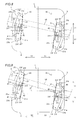
- the display screen portion 50 can be rotated clockwise by ⁇ ° in plan view, similarly to the case of rotating only the slide member 31 of the left rotation support portion 3 as shown in Fig. 7 .
- the positions of the display screen portion 50 in the anteroposterior direction are different from each other, while the rotation angle thereof remains at ⁇ °. More specifically, the display screen portion 50 shown in Fig. 10 is arranged on a position frontward beyond that shown in Fig. 7 .
- the display screen turning apparatus 1 can horizontally rotate the display screen portion 50 along a plurality of different rotational tracks, and has a higher degree of freedom in arrangement of the display screen portion 50 as compared with a case of rotating the display screen portion 50 along a single rotational track.
- the display screen turning apparatus 1 is provided with the right rotation support portion 2 formed to be horizontally rotatable with respect to the base 4 and the left rotation support portion 3 formed to be horizontally rotatable with respect to the base 4 independently of the right rotation support portion 2 and formed to horizontally rotate the display screen portion 50 by rotating at least either the right rotation support portion 2 or the left rotation support portion 3 so that the display screen portion 50 is rotated along different rotational tracks when only the right rotation support portion 2 is rotated, only the left rotation support portion 3 is rotated and both of the right and left rotation support portions 2 and 3 are rotated respectively, whereby the degree of freedom in arrangement (direction and position) of the display screen portion 50 can be improved.
- the display screen portion 50 is so supported by the right and left rotation support portions 2 and 3 that the same may not be self-supported on the base 4. Therefore, the display screen portion 50 can be stably supported by the right and left rotation support portions 2 and 3 also when the same is thinly formed.
- the support member 22 is formed to support the right side of the display screen portion 50 as viewed from the front side and to horizontally rotate with respect to the slide member 21 following movement of the slide member 31 while the support member 32 is formed to support the left side of the display screen portion 50 as viewed from the front side and to horizontally rotate with respect to the slide member 31 following movement of the slide member 21 so that the support member 32 (support member 22) supporting a second side (first side) is also rotated when the slide member 21 (slide member 31) supporting the first side (second side) is rotated, whereby the display screen portion 50 can be smoothly rotated.
- the base 4 is provided with the guide portions 41 guiding rotation of the slide members 21 and 31 upon horizontal rotation of the slide members 21 and 31, whereby the display screen portion 50 can be smoothly rotated by rotating the slide members 21 and 31 along the guide portions 41.
- the slide member 21 (slide member 31) is provided with the protrusions 21b (31b) coming into contact with the guide portions 41 thereby controlling rotation of the slide member 21 (slide member 31) with respect to the base 4, whereby the display screen portion 50 can be easily prevented from rotation in excess of a prescribed angle with the protrusions 21b (31b).
- the guide portions 41 of the base 4 are formed to inhibit the slide members 21 and 31 from floating up from the base 4 respectively, whereby the slide members 21 and 31 can be inhibited from floating up from the base 4 when horizontally rotating the display screen portion 50.
- the projecting portions 21f (31f) are provided on the surface of the slide member 21 (slide member 31) coming into contact with the base 4 and the slide member 21 (slide member 31) is formed to horizontally rotate when the projecting portions 21f (31f) slide with respect to the base 4 so that the slide member 21 (slide member 31) rotates while only the projecting portions 21f (31f) are in contact with the base 4, whereby the range of abrasions caused on the members 21 and 31 due to friction in rotation can be restricted.
- the protrusions 21b are integrally provided on both ends of the side portion 21a of the slide member 21 (side portion 31a of the slide member 31), whereby the display screen portion 50 can be easily prevented from rotation in excess of the prescribed angle regardless of the rotational direction of the slide member 21 (slide member 31), while increase in the number of components is suppressed due to the protrusions 21b (protrusions 31b) integrally provided on both ends of the side portion 21a (31a).
- the guided side portion 21a (31a) of the slide member 21 (slide member 31) is arcuately formed, whereby the display screen portion 50 can be smoothly rotated by rotating the slide member 21 (slide member 31) so that the arcuate side portion 21a (31a) is along the guide portions 41.
- the protrusions 21b are formed to protrude in the radial direction of the arc formed by the side portion 21a of the slide member 21 while the protrusions 31b are formed to protrude in the radial direction of the arc formed by the side portion 31a of the slide member 31, whereby the display screen portion 50 can be easily prevented from rotation in excess of the prescribed angle due to the protrusions 21b (protrusions 31b) having the simple shapes protruding in the radial direction of the arc formed by the side portion 21a (31a) of the slide member 21 (slide member 31).
- the guide portions 41 are integrally formed on the base 4, whereby increase in the number of components can be suppressed.
- the first disengagement preventing portions 42 (second disengagement preventing portions 43) are provided on the base 4 to vertically protrude upward from the upper surface of the base 4 to prevent the slide member 21 from disengagement by coming into contact with the slide member 21 upon rotation of the slide member 21 while preventing the slide member 31 from disengagement by coming into contact with the slide member 31 upon rotation of the slide member 31, whereby the slide members 21 and 31 can be easily prevented from disengaging from the base 4 respectively due to the first disengagement preventing portions 42 (second disengagement preventing portions 43) having the simple structure vertically protruding upward from the upper surface of the base 4.
- the first disengagement preventing portions 42 (second disengagement preventing portions 43) are integrally formed on the base 4, whereby increase in the number of components can be suppressed.
- a display screen turning apparatus 100 according to a second embodiment of the present invention is now described with reference to Figs. 11 to 15 .
- a display screen portion 50 can be rotated also in the anteroposterior direction in addition to the horizontal direction, dissimilarly to the aforementioned first embodiment.
- the display screen turning apparatus 100 includes a right rotation support portion 102, a left rotation support portion 103 and a base 4 of sheet metal, as shown in Figs. 11 to 14 .
- the right rotation support portion 102 is an example of the "first rotation support portion” in the present invention
- the left rotation support portion 103 is an example of the "second rotation support portion” in the present invention.
- the right rotation support portion 102 is formed to support the right side (along arrow X2) of the display screen portion 50 as viewed from the front side and to rotate in the horizontal direction (along arrows A1 and A2) with respect to the base 4 independently of the left rotation support portion 103. More specifically, the right rotation support portion 102 includes a slide member 21 of sheet metal and a support member 122, and the slide member 21 is formed to horizontally rotate with respect to the base 4, while the support member 122 is formed to support the right side (along arrow X2) of the display screen portion 50 as viewed from the front side.
- the support member 122 is an example of the "first support member" in the present invention.
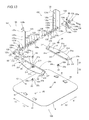
- the support member 122 includes a display screen support member 123, a base-side support member 124, a platelike support shaft 125 of sheet metal, a stop member 126 of sheet metal, two disc springs 127 of metal, two pressure plates 128 of sheet metal and a plate member 129 coming into contact with the two disc springs 127 of metal, as shown in Fig. 13 .
- the display screen support member 123 has a platelike upright portion 123a formed to extend in the vertical direction (along arrows Z1 and Z2) as shown in Figs. 11 to 13 , and the platelike upright portion 123 is so arranged that the thickness direction thereof is along the horizontal direction (along arrows X1 and X2) in a state where the display screen portion 50 is not rotated.
- a platelike mounting portion 123b folded along arrow X1 is integrally formed on the front side (along arrow Y1) of the upright portion 123a.
- the platelike mounting portion 123b is so arranged that the thickness direction thereof is along the anteroposterior direction (along arrows Y1 and Y2) in the state where the display screen portion 50 is not rotated.
- the lower end of the mounting portion 123b is arranged on a position higher than a folded side portion 21c of the slide member 21, as shown in Fig. 15 .
- Two threaded holes 123c are formed in the upper portion of the mounting portion 123b at a prescribed distance from each other in the vertical direction.
- the back surface of the right side (along arrow X2) of the display screen portion 50 as viewed from the front side is mounted on the support member 122 with screws (not shown) inserted into the threaded holes 123c.
- a sectorial first hole 123d is formed in the vicinity of the lower end of the upright portion 123a, as shown in Fig. 13 .
- the sectorial first hole 123d is provided for receiving the platelike support shaft 125.
- the sectorial first hole 123d is so arranged that the base closer to the center of a hole is positioned on the upper side and brought into contact with the upper surface of the support shaft 125.
- the display screen support member 123 is formed to be rotatable with respect to the platelike support shaft 125 in a sectorial angular range around the base of the sectorial firs hole 123d supported by the platelike support shaft 125.
- the platelike support shaft 125 of sheet metal functions as the rotating shaft of the display screen support member 123.
- the base-side support member 124 has an arcuate portion 124a provided with an arcuately formed upper portion, and the arcuate portion 124a is so arranged that the thickness direction thereof is along the horizontal direction (along arrows X1 and X2).
- a platelike set portion 124b horizontally folded along arrow X2 is integrally formed on the lower side of the arcuate portion 124a.
- the platelike set portion 124b is in the form of a horizontal plane, as shown in Fig. 15 .
- the set portion 124b has a circular through-hole 124c formed to receive a body portion 23b of a shaft portion 23, as shown in Fig. 13 .
- the support member 122 is arranged on the slide member 21 through a washer 24, and mounted on the slide member 21 by fitting a nut 25 with a screw portion 23c of the shaft portion 23.
- the support member 122 is horizontally rotatable with respect to the slide member 21.
- the support member 122 is formed to horizontally rotate with respect to the slide member 21 following rotation of a slide member 31 of the left rotation support portion 103.
- a sectorial second hole 124d is provided in the arcuate portion 124a of the base-side support member 124, as shown in Fig. 13 .
- the sectorial second hole 124d is provided for receiving the platelike support shaft 125.
- the sectorial second hole 124d is so arranged that the base closer to the center of a hole is positioned on the upper side and brought into contact with the lower surface of the support shaft 125.
- the support shaft 125 is formed to be rotatable with respect to the base-side support member 124 in a sectorial angular range around the base of the sectorial second hole 124d of the base-side support member 124.
- the platelike support shaft 125 of sheet metal is formed substantially in a T-shaped manner, as shown in Fig. 13 .
- a rectangular hole 125a is formed in the vicinity of an end of the support shaft 125 along arrow X2, for receiving the stop member 126.
- the stop member 126 of sheet metal is in the form of a wedge. When inserted into the rectangular hole 125a provided in the platelike support shaft 125, therefore, the stop member 126 can be easily inhibited from coming off the hole 125a.
- the two disc springs 127 of metal are arranged on the inner side of one of the pressure plates 128 arranged inside the display screen support member 123 in a state overlapped to be convexed toward each other.
- the two pressure plates 128 are provided with rectangular holes 128a for receiving the support shaft 125 respectively.
- the two pressure plates 128 are arranged on the inner side of the display screen support member 123 and on the outer side of the base-side support member 124 respectively.
- the plate member 129 is provided with a rectangular hole 129a for receiving the support shaft 125. Further, the plate member 129 is arranged on the inner side of the disc springs 127.
- the support member 122 can be anteroposteriorly rotated around the platelike support shaft 125 of sheet metal serving as the rotating shaft due to the aforementioned structure, whereby the display screen portion 50 can also be anteroposteriorly rotated as a result.
- the display screen support member 123 and the base-side support member 124 are pressed against each other due to urging force of the two disc springs 127, whereby frictional force of a prescribed magnitude acts therebetween.
- the display screen portion 50 is anteroposteriorly inclined, the inclined state can be maintained due to the frictional force.
- the left rotation support portion 103 is formed to support the left side (along arrow X1) of the display screen portion 50 as viewed from the front side, and to horizontally rotate (along arrows B1 and B2) with respect to the base 4 independently of the right rotation support portion 102. More specifically, the left rotation support portion 103 includes the slide member 31 of sheet metal and a support member 132, and the slide member 31 is formed to horizontally rotate with respect to the base 4, while the support member 132 is formed to support the left side (along arrow X1) of the display screen portion 50 as viewed from the front side.
- the support member 132 is an example of the "second support member" in the present invention.
- the support member 132 of the left rotation support portion 103 is similar in structure to the support member 122 of the right rotation support member 102, and bilaterally symmetrical to the support member 122 of the right rotation support member 102. Therefore, redundant description of the support member 132 of the left rotation support portion 103 is omitted.
- a display screen support member 133, a base-side support member 134, a platelike support shaft 135 of sheet metal, a stop member 136 of sheet metal 136, two disc springs 137 of metal, two pressure plates 138 of sheet metal and a plate member 139 of the support member 132 of the left rotation support portion 103 correspond to the display screen support member 123, the base-side support member 124, the platelike support shaft 125 of sheet metal, the stop member 126 of sheet metal, the two disc springs 127 of metal, the two pressure plates 128 of sheet metal and the plate member 129 of the support member 122 of the right rotation support portion 102 respectively.
- an upright portion 133a, a mounting portion 133b, threaded holes 133c and a first hole 133d of the display screen support member 133 of the left rotation support portion 103 correspond to the upright portion 123a, the mounting portion 123b, the threaded holes 123c and the first hole 123d of the display screen support member 123 of the right rotation support portion 102 respectively, while an arcuate portion 134a, a set portion 134b, a through-hole 134c and a second hole 134d of the base-side support member 134 of the left rotation support portion 103 correspond to the arcuate portion 124a, the set portion 124b, the through-hole 124c and the second hole 124d of the base-side support member 124 of the right rotation support portion 102 respectively.
- holes 135a, 138a and 139a of the support shaft 135, the pressure plate 138 and the plate member 139 of the left rotation support portion 103 correspond to the holes 125a, 128a and 129a of the support shaft 125, the pressure plate 128 and the plate member 129 of the right rotation support portion 102 respectively.
- the remaining structure of the second embodiment is similar to that of the aforementioned first embodiment.
- the display screen portion 50 is formed to be anteroposteriorly rotatable so that the same can be rotated also in the anteroposterior direction in addition to the horizontal direction, whereby the degree of freedom in arrangement of the display screen portion 50 can be further improved.
- first and second support members are formed to be horizontally rotatable with respect to the first and second slide members respectively in each of the aforementioned first and second embodiments
- the present invention is not restricted to this, but the first and second support members may alternatively be unrotational with respect to the first and second slide members respectively.
- each slide member slide with respect to the base in each of the aforementioned first and second embodiments
- the present invention is not restricted to this, but the overall surface of the slide member closer to the base may alternatively be rendered slidable, or a sheet of Teflon (registered trademark) or the like for reducing frictional resistance may be provided between the slide member and the base.
- disengagement preventing portions formed by drawing are shown as the examples of the disengagement preventing portion in each of the aforementioned first and second embodiments, the present invention is not restricted to this, but disengagement preventing portions 142 and 143 formed by burring may alternatively be employed, as shown in Fig. 16 .
- the present invention is not restricted to this, but a single or at least three guide portions may alternatively be provided on each of the slide members 21 and 31. Further alternatively, the numbers of the guide portions provided on the slide members 21 and 31 may be different from each other.
- first and second rotation control portions may alternatively be formed to extend upward from both ends of the slide members or convexly formed on the slide members, so far as the same come into contact with the guide portions.
- slide members having the folded inner side portions are shown as the examples of the slide members in each of the aforementioned first and second embodiments, the present invention is not restricted to this, but both anteroposterior ends (along arrows Y1 and Y2) of the slide members may alternatively be folded, or the slide members may have no folded portions at all.
Landscapes
- Engineering & Computer Science (AREA)
- General Engineering & Computer Science (AREA)
- Mechanical Engineering (AREA)
- Devices For Indicating Variable Information By Combining Individual Elements (AREA)
Abstract
Description
- The present invention relates to a display screen turning apparatus, and more particularly, it relates to a display screen turning apparatus having a display screen portion formed to be horizontally rotatable.
- A display screen turning apparatus having a display screen portion formed to be horizontally rotatable is known in general. Such a display screen turning apparatus is disclosed in each of Japanese Patent Laying-Open Nos.
2008-51830 2005-284087 10-131944 (1998 7-240890 (1995 2000-184314 - The aforementioned Japanese Patent Laying-Open No.
2008-51830 - The aforementioned Japanese Patent Laying-Open No.
2005-284087 - The aforementioned Japanese Patent Laying-Open No.
10-131944 - The aforementioned Japanese Patent Laying-Open No.
7-240890 - The aforementioned Japanese Patent Laying-Open No.
2000-184314 2000-184314 - However, while the display screen portion is horizontally rotatable around the upright portion, the main shaft, the rotation support protrusion or the central axis of the arc formed by the arcuate ribs serving as the center of rotation in each of the display screen turning apparatuses described in the aforementioned Japanese Patent Laying-Open Nos.
2008-51830 2005-284087 10-131944 7-240890 - In the rotating apparatus described in the aforementioned Japanese Patent Laying-Open No.
2000-184314 2008-51830 2005-284087 10-131944 7-240890 2000-184314 - The present invention has been proposed in the light of the aforementioned problems, and a preferred aim of the present invention is to provide a display screen turning apparatus having a high degree of freedom in arrangement of a display screen portion and capable of stably supporting the display screen portion regardless of the shape thereof.
- A display screen turning apparatus according to an aspect of the present invention includes a base, a first rotation support portion provided separately from the base for supporting a display screen portion and formed to be horizontally rotatable with respect to the base and a second rotation support portion provided separately from the base for supporting the display screen portion and formed to be horizontally rotatable with respect to the base independently of the first rotation support portion, for horizontally rotating the display screen portion by rotating at least either the first rotation support portion or the second rotation support portion.
- As hereinabove described, the display screen turning apparatus according to this aspect of the present invention is provided with the first rotation support portion formed to be horizontally rotatable with respect to the base and the second rotation support portion formed to be horizontally rotatable with respect to the base independently of the first rotation support portion for horizontally rotating the display screen portion by rotating at least either the first rotation support portion or the second rotation support portion so that the display screen portion is rotated along different rotational tracks when only the first rotation support portion is rotated, only the second rotation support portion is rotated and both of the first and second rotation support portions are rotated respectively, whereby the degree of freedom in arrangement (direction and position) of the display screen portion can be increased. Further, the display screen portion is so supported by the first and second rotation support portions that the same may not be self-supported on the base. Therefore, the display screen portion can be stably supported by the first and second rotation support portions also when the same is thinly formed.
- In the display screen turning apparatus according to the aforementioned aspect, at least either the first rotation support portion or the second rotation support portion preferably includes a slide member formed to horizontally slide with respect to the base and a support member, supporting the display screen portion, formed to be horizontally rotatable with respect to the slide member. According to this structure, the display screen portion can be smoothly horizontally rotated by horizontally rotating the support member provided on either the first rotation support portion or the second rotation support portion with respect to the slide member when either the second rotation support portion or the first rotation support portion slides with respect to the base.
- In this case, the slide member preferably includes a first slide member, constituting the first rotation support portion, formed to horizontally slide with respect to the base and a second slide member, constituting the second rotation support portion, formed to horizontally slide with respect to the base, and the support member preferably includes a first support member, constituting the first rotation support portion along with the first slide member, formed to be horizontally rotatable with respect to the first slide member and a second support member, constituting the second rotation support portion along with the second slide member, formed to be horizontally rotatable with respect to the second slide member. According to this structure, the second support member (first support member) can be horizontally rotated with respect to the second slide member (first slide member) when the first slide member (second slide member) slides with respect to the base, whereby the display screen portion can be more smoothly horizontally rotated.
- In the aforementioned structure including the first support member and the second support member, the first support member is preferably formed to support a first horizontal side of the display screen portion as viewed from the front side and to horizontally rotate with respect to the first slide member following movement of the second slide member, and the second support member is preferably formed to support a second horizontal side of the display screen portion as viewed from the front side and to horizontally rotate with respect to the second slide member following movement of the first slide member. According to this structure, the second support member (first support member) supporting the second horizontal side (first horizontal side) is also rotated when the first slide member (second slide member) of the first horizontal side (second horizontal side) is rotated, whereby the display screen portion can be more smoothly rotated.
- In the aforementioned structure including the first slide member and the second slide member, the base preferably includes a guide portion guiding rotation of the first slide member and the second slide member when the first slide member and the second slide member horizontally rotate respectively. According to this structure, the display screen portion can be more smoothly rotated by rotating the first slide member and the second slide member along the guide portion.
- In the aforementioned structure having the base including the guide portion, the first slide member preferably has a first rotation control portion controlling rotation of the first slide member by coming into contact with the guide portion when the first slide member rotates with respect to the base portion, and the second slide member preferably has a second rotation control portion controlling rotation of the second slide member by coming into contact with the guide portion when the second slide member rotates with respect to the base. According to this structure, the display screen portion can be easily prevented from rotation in excess of a prescribed angle with the first and second rotation control portions.
- In the aforementioned structure including the first rotation control member and the second rotation control member, the first rotation control portion and the second rotation control portion are preferably integrally provided on both ends of side portions of the first slide member and the second slide member guided by the guide portion respectively. According to this structure, the display screen portion can be easily prevented from rotation in excess of the prescribed angle regardless of the rotational direction of the first slide member (second slide member), while increase in the number of components is suppressed due to the first rotation control portion (second rotation control portion) integrally provided on each end of the corresponding side portion.
- In the aforementioned structure having the base including the guide portion, the guide portion of the base is preferably formed to inhibit the first slide member and the second slide member from floating up from the base respectively. According to this structure, the first and second slide members can be inhibited from floating up from the base when the display screen portion is horizontally rotated.
- In the aforementioned structure having the base including the guide portion, the guide portion is preferably integrally formed on the base. According to this structure, increase in the number of components can be suppressed.
- In the aforementioned structure including the first slide member and the second slide member, the first slide member and the second slide member preferably have projecting portions on surfaces coming into contact with the base respectively, and are formed to horizontally rotate when the projecting portions slide with respect to the base. According to this structure, the first slide member and the second slide member rotate while only the projecting portions are in contact with the base, whereby the range of abrasions caused on the members due to friction in rotation can be restricted.
- In the aforementioned structure including the first slide member and the second slide member, the base preferably includes a disengagement preventing portion preventing disengagement of the first slide member and the second slide member. According to this structure, the first slide member and the second slide member can be prevented from disengaging from the base respectively, whereby the display screen portion can be more stably supported by the first rotation support portion and the second rotation support portion.
- In the aforementioned structure including the disengagement preventing portion, the disengagement preventing portion is preferably provided on the base to vertically protrude upward from the upper surface of the base and formed to prevent disengagement of the first slide member by coming into contact with the first slide member when the first slide member rotates and to prevent disengagement of the second slide member by coming into contact with the second slide member when the second slide member rotates. According to this structure, the first slide member and the second slide member can be easily prevented from disengaging from the base respectively by the disengagement preventing portion having the simple structure vertically protruding upward from the upper surface of the base.
- In the aforementioned structure including the disengagement preventing portion, the disengagement preventing portion is preferably integrally provided on the base. According to this structure, increase in the number of components can be suppressed.
- In the aforementioned structure including the first slide member and the second slide member, the first slide member and the second slide member preferably have side portions vertically folded upward respectively. According to this structure, rigidity of the first slide member (second slide member) can be improved due to the folded side portion.
- In the aforementioned structure including the first support member and the second support member, the first support member and the second support member are preferably formed to support the display screen portion to be anteroposteriorly rotatable respectively. According to this structure, the display screen portion can be rotated also in the anteroposterior direction in addition to the horizontal direction, whereby the degree of freedom in arrangement of the display screen portion can be further improved.
- The foregoing and other objects, features, aspects and advantages of the present invention will become more apparent from the following detailed description of the present invention when taken in conjunction with the accompanying drawings.
-
-
Fig. 1 is a perspective view showing the overall structure of a liquid crystal display provided with a display screen turning apparatus according to a first embodiment of the present invention; -
Fig. 2 is a perspective view showing the overall structure of the display screen turning apparatus according to the first embodiment of the present invention shown inFig. 1 ; -
Fig. 3 is an exploded perspective view showing the overall structure of the display screen turning apparatus according to the first embodiment of the present invention shown inFig. 1 ; -
Fig. 4 is a plan view showing the overall structure of the display screen turning apparatus according to the first embodiment of the present invention shown inFig. 1 ; -
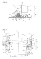
Fig. 5 is a rear elevational view showing the overall structure of the display screen turning apparatus according to the first embodiment of the present invention shown inFig. 1 ; -
Fig. 6 is a sectional view taken along the line 100-100 inFig. 4 ; -
Figs. 7 to 10 are plan views for illustrating a rotating operation of the display screen turning apparatus according to the first embodiment of the present invention shown inFig. 1 ; -
Fig. 11 is a perspective view showing the overall structure of a liquid crystal display provided with a display screen turning apparatus according to a second embodiment of the present invention; -
Fig. 12 is a perspective view showing the overall structure of the display screen turning apparatus according to the second embodiment of the present invention shown inFig. 11 ; -
Fig. 13 is an exploded perspective view showing the overall structure of the display screen turning apparatus according to the second embodiment of the present invention shown inFig. 11 ; -
Fig. 14 is a plan view showing the overall structure of the display screen turning apparatus according to the second embodiment of the present invention shown inFig. 11 ; -
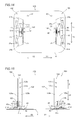
Fig. 15 is a rear elevational view showing the overall structure of the display screen turning apparatus according to the second embodiment of the present invention shown inFig. 11 ; and -
Fig. 16 is a plan view showing a modification of the display screen turning apparatus according to each of the first and second embodiments of the present invention.
Embodiments of the present invention are now described with reference to the drawings. - The structure of a display
screen turning apparatus 1 according to a first embodiment of the present invention is described with reference toFigs. 1 to 6 . - The display
screen turning apparatus 1 according to the first embodiment of the present invention includes a rightrotation support portion 2, a leftrotation support portion 3 and abase 4 of sheet metal, as shown inFigs. 1 to 3 . The rightrotation support portion 2 is an example of the "first rotation support portion" in the present invention, and the leftrotation support portion 3 is an example of the "second rotation support portion" in the present invention. - The right
rotation support portion 2 is formed to support the right side (along arrow X2) of adisplay screen portion 50 as viewed from the front side and to rotate in the horizontal direction (along arrows A1 and A2) with respect to thebase 4 independently of the leftrotation support portion 3. More specifically, the rightrotation support portion 2 includes aslide member 21 of sheet metal in the form of a horizontal plane and asupport member 22 of sheet metal. Theslide member 21 is formed to horizontally rotate with respect to thebase 4, while thesupport member 22 is formed to support the right side (along arrow X2) of thedisplay screen portion 50 as viewed from the front side. Theslide member 21 is an example of the "first slide member" in the present invention, and thesupport member 22 is an example of the "first support member" in the present invention. - According to the first embodiment, the
slide member 21 is arranged on a side of thebase 4 along arrow X2 in plan view, as shown inFig. 4 . In theslide member 21, anouter side portion 21a (along arrow X2) is in the form of an arc, having a radius r, centering on a shaft portion 33 (described later) of the leftrotation support portion 3 in the state (shown inFig. 4 ) where thedisplay screen portion 50 is not rotated.Protrusions 21b protruding in the radial direction of the arc formed by theside portion 21a are integrally formed on both ends of thearcuate side portion 21a respectively. Theprotrusions 21b have functions of controlling rotation of theslide member 21 by coming into contact with guide portions 41 (described later) of thebase 4 when theslide member 21 rotates with respect to thebase 4. Theprotrusions 21b are examples of the "first rotation control portion" in the present invention. - An
inner side portion 21c (along arrow X1) of theslide member 21 is in the form of a straight line extending in the anteroposterior direction (along arrows Y1 and Y2) in the state (shown inFig. 4 ) where thedisplay screen portion 50 is not rotated. Thelinear side portion 21c is vertically folded upward (along arrow Z1), as shown inFigs. 1 to 3 ,5 and6 . Thus, rigidity (mechanical strength) of theslide member 21 is improved. - A substantially central portion of the
slide member 21 is drawn to protrude upward as shown inFigs. 3 to 6 , and acrest portion 21d circular in plan view is integrally formed on theslide member 21. The upper surface of thecrest portion 21d is substantially in the form of a horizontal plane. A circular through-hole 21e capable of receiving ashaft portion 23 is formed in a substantially central portion of thecrest portion 21d in plan view, as shown inFigs. 3 and6 . Ahead portion 23a of theshaft portion 23 is arranged under the lower surface of thecrest portion 21d concaved by the drawing as shown inFig. 6 , and abody portion 23b of theshaft portion 23 is inserted into the through-hole 21e. - The
slide member 21 has downwardly protruding projectingportions 21f on a surface (along arrow Z2) coming into contact with thebase 4, as shown inFig. 6 . Three pairs of such projectingportions 21f are formed in the vicinity of the central portion, the front end (along arrow Y1) and the rear end (along arrow Y2) of theslide member 21 in plan view respectively, as shown inFigs. 3 and4 . The projectingportions 21f are circular in plan view, and surfaces thereof coming into contact with thebase 4 are in the form of horizontal planes. The six projectingportions 21f are formed to protrude from the lower surface (along arrow Z2) of theslide member 21 in the same height respectively. Thus, theslide member 21 can be placed on thebase 4 in a horizontal state while separating portions of the lower surface of theslide member 21 other than the projectingportions 21f from thebase 4. Theslide member 21 is formed to horizontally rotate when the six projectingportions 21f slide with respect to thebase 4. - The
support member 22 has a platelikeupright portion 22a formed to extend in the vertical direction (along arrows Z1 and Z2) as shown inFigs. 1 to 3 , and the platelikeupright portion 22a is so arranged that the thickness direction thereof is along the anteroposterior direction (along arrows Y1 and Y2) in the state (shown inFig. 4 ) where thedisplay screen portion 50 is not rotated. Aplatelike set portion 22b folded along arrow X2 is integrally formed on the lower end of theupright portion 22a. Theplatelike set portion 22b is in the form of a horizontal plane, as shown inFigs. 5 and6 . Theset portion 22b has a circular through-hole 22d formed to receive thebody portion 23b of theshaft portion 23, as shown inFigs. 3 and6 . Thesupport member 22 is arranged on theslide member 21 through awasher 24 and mounted on theslide member 21 by fitting anut 25 with ascrew portion 23c of theshaft portion 23, as shown inFig. 6 . Thus, thesupport member 22 is horizontally rotatable with respect to theslide member 21. Thesupport member 22 is formed to horizontally rotate with respect to theslide member 21 following rotation of a slide member 31 (described later) of the leftrotation support portion 3. - As shown in
Figs. 1 to 3 , aplatelike mounting portion 22c folded along arrow X1 is integrally formed on the front side (along arrow Y1) of theupright portion 22a of thesupport member 22. Theplatelike mounting portion 22c is so arranged that the thickness direction thereof is along the anteroposterior direction (along arrows Y1 and Y2) in the state (shown inFig. 4 ) where thedisplay screen portion 50 is not rotated. The lower end of the mountingportion 22c is arranged on a position higher than the foldedside portion 21c of theslide member 21, as shown inFigs. 5 and6 . Thus, the mountingportion 22c is not brought into contact with theside portion 21c of theslide member 21, whereby thesupport member 22 is smoothly horizontally rotatable. Two threadedholes 22e are formed in the upper portion of the mountingportion 22c at a prescribed distance from each other in the vertical direction. The back surface of the right side (along arrow X2) of thedisplay screen portion 50 as viewed from the front side is mounted on thesupport member 22 with screws (not shown) inserted into the threadedholes 22e, as shown inFig. 1 . Thus, thesupport member 22 is coupled to the leftrotation support portion 3 through thedisplay screen portion 50, as described later. When the leftrotation support portion 3 is horizontally rotated with respect to thebase 4, therefore, thesupport member 22 is horizontally rotated with respect to theslide member 21 following the rotation of the leftrotation support portion 3. - The left
rotation support portion 3 is formed to support the left side (along arrow X1) of thedisplay screen portion 50 as viewed from the front side and to horizontally rotate (along arrows B1 and B2) with respect to thebase 4 independently of the rightrotation support portion 2. More specifically, the leftrotation support portion 3 includes theslide member 31 of sheet metal and asupport member 32 of sheet metal. Theslide member 31 is formed to horizontally rotate with respect to thebase 4, while thesupport member 32 is formed to support the left side (along arrow X1) of thedisplay screen portion 50 as viewed from the front side. Theslide member 31 is an example of the "second slide member" in the present invention, and thesupport member 32 is an example of the "second support member" in the present invention. - The
slide member 31 and thesupport member 32 of the leftrotation support portion 3 are similar in structure to theslide member 21 and thesupport member 22 of the rightrotation support portion 2 respectively, and bilaterally symmetrical to theslide member 21 and thesupport member 22 of the rightrotation support portion 2 respectively. Therefore, redundant description of theslide member 31 and thesupport member 32 of the leftrotation support portion 3 is omitted. As shown inFig. 3 , anarcuate side portion 31a,protrusions 31b, alinear side portion 31c, acrest portion 31d, a through-hole 31e and projectingportions 31f of theslide member 31 of the leftrotation support portion 3 correspond to thearcuate side portion 21a, the projectingportions 21b, thelinear side portion 21c, thecrest portion 21d, the through-hole 21e and the projectingportions 21f of theslide member 21 of the rightrotation support portion 2 respectively. Further, anupright portion 32a, aset portion 32b, a mountingportion 32c, a through-hole 32d and threadedholes 32e of thesupport member 32 of the leftrotation support portion 3 correspond to theupright portion 22a, theset portion 22b, the mountingportion 22c, the through-hole 22d and the threadedholes 22e of thesupport member 22 of the rightrotation support portion 2 respectively, while theshaft portion 33, ahead portion 33a, abody portion 33b, ascrew portion 33c, awasher 34 and anut 35 of the leftrotation support portion 3 correspond to theshaft portion 23, thehead portion 23a, thebody portion 23b, thescrew portion 23c, thewasher 24 and thenut 25 of the rightrotation support portion 2 respectively. The projectingportions 31b are examples of the "second rotation control portion" in the present invention. - As hereinabove described, the right
rotation support portion 2 and the leftrotation support portion 3 are horizontally rotatable with respect to thebase portion 4 independently of each other, and the displayscreen turning apparatus 1 according to the first embodiment is formed to be capable of horizontally rotating thedisplay screen portion 50 by rotating at least either the rightrotation support portion 2 or the leftrotation support portion 3. Thedisplay screen portion 50 can also be rotated by rotating both of the rightrotation support portion 2 and the leftrotation support portion 3. - The
base 4 is in the form of a platelike horizontal plane, as shown inFigs. 1 to 4 . Further, thebase 4 is substantially in the form of a rectangle having arcuate corner portions in plan view, and is arranged to be longitudinal in the horizontal direction (along arrows X1 and X2). Thebase 4 has theguide portions 41 integrally formed thereon by partially uprighting thebase 4 to be along thearcuate side portions slide members display screen portion 50 is not rotated, as shown inFig. 4 . - Two pairs of
such guide portions 41 are provided on theslide members slide members guide portions 41 guide the rotation of theslide members side portions guide portions 41 are raised up to a height slightly larger than the thickness of theslide members guide portions 41 are formed to horizontally extend inward from the outer side of thebase 4. Further, theguide portions 41 are arranged to overlap with parts of theslide members slide members base 4. - On substantially central portions in the anteroposterior direction (along arrows Y1 and Y2), the
base 4 has two firstdisengagement preventing portions 42 integrally formed thereon by drawing to vertically protrude upward on positions inward beyond theside portions slide members display screen portion 50 is not rotated, as shown inFig. 4 . Thebase 4 further has two seconddisengagement preventing portions 43 arranged inward beyond the two firstdisengagement preventing portions 42 in front of theslide members 21 and 31 (along arrow Y1) in the state where thedisplay screen portion 50 is not rotated. The seconddisengagement preventing portions 43 are integrally formed on thebase 4 by drawing to vertically protrude upward, similarly to the firstdisengagement preventing portions 42. The firstdisengagement preventing portions 42 and the seconddisengagement preventing portions 43 are examples of the "disengagement preventing portion" in the present invention respectively. - The first
disengagement preventing portion 42 and the seconddisengagement preventing portion 43 provided along arrow X2 are formed to prevent theslide member 21 from disengaging inward (along arrow X1) beyond the firstdisengagement preventing portion 42 and the seconddisengagement preventing portion 43 upon rotation of theslide member 21 respectively. On the other hand, the firstdisengagement preventing portion 42 and the seconddisengagement preventing portion 43 provided along arrow X1 are formed to prevent theslide member 31 from disengaging inward (along arrow X2) beyond the firstdisengagement preventing portion 42 and the seconddisengagement preventing portion 43 upon rotation of theslide member 31 respectively. In other words, the firstdisengagement preventing portions 42 and the seconddisengagement preventing portions 43 are arranged on opposed sides of theslide members slide members disengagement preventing portions base 4 upon rotation, whereby thedisplay screen portion 50 can be stably supported by the rightrotation support portion 2 and the leftrotation support portion 3. The firstdisengagement preventing portions 42 and the seconddisengagement preventing portions 43 are circularly formed in plan view respectively, to be smoothly brought into contact with theslide members - A rotating operation of the display
screen turning apparatus 1 according to the first embodiment of the present invention is now described with reference toFigs. 4 and7 to10 . - When the
slide member 31 of the leftrotation support portion 3 is rotated along theguide portions 41 along arrow B2 as shown inFig. 7 from the state where thedisplay screen portion 50 is not rotated as shown inFig. 4 , thesupport member 22 of the rightrotation support portion 2 is horizontally rotated with respect to theslide member 21 following the rotation of theslide member 31. When theslide member 31 is rotated by a prescribed angle, thefront projecting portion 31b (along arrow Y1) of theslide member 31 is brought into contact with thecorresponding guide portion 41, to control the rotation of theslide member 31. Thus, thedisplay screen portion 50 is rotated clockwise by α° in plan view. - When the
slide member 21 of the rightrotation support portion 2 is thereafter rotated along arrow A1 as shown inFig. 8 , thesupport member 32 of the leftrotation support portion 3 is horizontally rotated with respect to theslide member 31 following the rotation of theslide member 21. When theslide member 21 is further rotated as shown inFig. 9 , therear projecting portion 21b (along arrow Y2) of theslide member 21 is brought into contact with thecorresponding guide portion 41, to control the rotation of theslide member 21. Thus, thedisplay screen portion 50 is rotated clockwise by β° in plan view. At this time, thelinear side portion 21c of theslide member 21 is brought into contact with the first and seconddisengagement preventing portions slide member 21 from deviating inward beyond the first and seconddisengagement preventing portions 42 and 43 (along arrow X1). - Also when both of the
slide members rotation support portions Fig. 10 , thedisplay screen portion 50 can be rotated clockwise by α° in plan view, similarly to the case of rotating only theslide member 31 of the leftrotation support portion 3 as shown inFig. 7 . In the states shown inFigs. 7 and10 , the positions of thedisplay screen portion 50 in the anteroposterior direction (along arrows Y1 and Y2) are different from each other, while the rotation angle thereof remains at α°. More specifically, thedisplay screen portion 50 shown inFig. 10 is arranged on a position frontward beyond that shown inFig. 7 . In other words, the displayscreen turning apparatus 1 according to the first embodiment can horizontally rotate thedisplay screen portion 50 along a plurality of different rotational tracks, and has a higher degree of freedom in arrangement of thedisplay screen portion 50 as compared with a case of rotating thedisplay screen portion 50 along a single rotational track. - According to the first embodiment, as hereinabove described, the display
screen turning apparatus 1 is provided with the rightrotation support portion 2 formed to be horizontally rotatable with respect to thebase 4 and the leftrotation support portion 3 formed to be horizontally rotatable with respect to thebase 4 independently of the rightrotation support portion 2 and formed to horizontally rotate thedisplay screen portion 50 by rotating at least either the rightrotation support portion 2 or the leftrotation support portion 3 so that thedisplay screen portion 50 is rotated along different rotational tracks when only the rightrotation support portion 2 is rotated, only the leftrotation support portion 3 is rotated and both of the right and leftrotation support portions display screen portion 50 can be improved. Further, thedisplay screen portion 50 is so supported by the right and leftrotation support portions base 4. Therefore, thedisplay screen portion 50 can be stably supported by the right and leftrotation support portions - According to the first embodiment, the
support member 22 is formed to support the right side of thedisplay screen portion 50 as viewed from the front side and to horizontally rotate with respect to theslide member 21 following movement of theslide member 31 while thesupport member 32 is formed to support the left side of thedisplay screen portion 50 as viewed from the front side and to horizontally rotate with respect to theslide member 31 following movement of theslide member 21 so that the support member 32 (support member 22) supporting a second side (first side) is also rotated when the slide member 21 (slide member 31) supporting the first side (second side) is rotated, whereby thedisplay screen portion 50 can be smoothly rotated. - According to the first embodiment, the
base 4 is provided with theguide portions 41 guiding rotation of theslide members slide members display screen portion 50 can be smoothly rotated by rotating theslide members guide portions 41. - According to the first embodiment, the slide member 21 (slide member 31) is provided with the
protrusions 21b (31b) coming into contact with theguide portions 41 thereby controlling rotation of the slide member 21 (slide member 31) with respect to thebase 4, whereby thedisplay screen portion 50 can be easily prevented from rotation in excess of a prescribed angle with theprotrusions 21b (31b). - According to the first embodiment, the
guide portions 41 of thebase 4 are formed to inhibit theslide members base 4 respectively, whereby theslide members base 4 when horizontally rotating thedisplay screen portion 50. - According to the first embodiment, the projecting
portions 21f (31f) are provided on the surface of the slide member 21 (slide member 31) coming into contact with thebase 4 and the slide member 21 (slide member 31) is formed to horizontally rotate when the projectingportions 21f (31f) slide with respect to thebase 4 so that the slide member 21 (slide member 31) rotates while only the projectingportions 21f (31f) are in contact with thebase 4, whereby the range of abrasions caused on themembers - According to the first embodiment, the
protrusions 21b (protrusions 31b) are integrally provided on both ends of theside portion 21a of the slide member 21 (side portion 31a of the slide member 31), whereby thedisplay screen portion 50 can be easily prevented from rotation in excess of the prescribed angle regardless of the rotational direction of the slide member 21 (slide member 31), while increase in the number of components is suppressed due to theprotrusions 21b (protrusions 31b) integrally provided on both ends of theside portion 21a (31a). - According to the first embodiment, the guided
side portion 21a (31a) of the slide member 21 (slide member 31) is arcuately formed, whereby thedisplay screen portion 50 can be smoothly rotated by rotating the slide member 21 (slide member 31) so that thearcuate side portion 21a (31a) is along theguide portions 41. - According to the first embodiment, the
protrusions 21b are formed to protrude in the radial direction of the arc formed by theside portion 21a of theslide member 21 while theprotrusions 31b are formed to protrude in the radial direction of the arc formed by theside portion 31a of theslide member 31, whereby thedisplay screen portion 50 can be easily prevented from rotation in excess of the prescribed angle due to theprotrusions 21b (protrusions 31b) having the simple shapes protruding in the radial direction of the arc formed by theside portion 21a (31a) of the slide member 21 (slide member 31). - According to the first embodiment, the
guide portions 41 are integrally formed on thebase 4, whereby increase in the number of components can be suppressed. - According to the first embodiment, the first disengagement preventing portions 42 (second disengagement preventing portions 43) are provided on the
base 4 to vertically protrude upward from the upper surface of thebase 4 to prevent theslide member 21 from disengagement by coming into contact with theslide member 21 upon rotation of theslide member 21 while preventing theslide member 31 from disengagement by coming into contact with theslide member 31 upon rotation of theslide member 31, whereby theslide members base 4 respectively due to the first disengagement preventing portions 42 (second disengagement preventing portions 43) having the simple structure vertically protruding upward from the upper surface of thebase 4. - According to the first embodiment, the first disengagement preventing portions 42 (second disengagement preventing portions 43) are integrally formed on the
base 4, whereby increase in the number of components can be suppressed. - The structure of a display
screen turning apparatus 100 according to a second embodiment of the present invention is now described with reference toFigs. 11 to 15 . According to the second embodiment, adisplay screen portion 50 can be rotated also in the anteroposterior direction in addition to the horizontal direction, dissimilarly to the aforementioned first embodiment. - The display
screen turning apparatus 100 according to the second embodiment of the present invention includes a rightrotation support portion 102, a leftrotation support portion 103 and abase 4 of sheet metal, as shown inFigs. 11 to 14 . The rightrotation support portion 102 is an example of the "first rotation support portion" in the present invention, and the leftrotation support portion 103 is an example of the "second rotation support portion" in the present invention. - The right
rotation support portion 102 is formed to support the right side (along arrow X2) of thedisplay screen portion 50 as viewed from the front side and to rotate in the horizontal direction (along arrows A1 and A2) with respect to thebase 4 independently of the leftrotation support portion 103. More specifically, the rightrotation support portion 102 includes aslide member 21 of sheet metal and asupport member 122, and theslide member 21 is formed to horizontally rotate with respect to thebase 4, while thesupport member 122 is formed to support the right side (along arrow X2) of thedisplay screen portion 50 as viewed from the front side. Thesupport member 122 is an example of the "first support member" in the present invention. - The
support member 122 includes a displayscreen support member 123, a base-side support member 124, aplatelike support shaft 125 of sheet metal, astop member 126 of sheet metal, two disc springs 127 of metal, twopressure plates 128 of sheet metal and aplate member 129 coming into contact with the two disc springs 127 of metal, as shown inFig. 13 . - The display
screen support member 123 has a platelikeupright portion 123a formed to extend in the vertical direction (along arrows Z1 and Z2) as shown inFigs. 11 to 13 , and the platelikeupright portion 123 is so arranged that the thickness direction thereof is along the horizontal direction (along arrows X1 and X2) in a state where thedisplay screen portion 50 is not rotated. Aplatelike mounting portion 123b folded along arrow X1 is integrally formed on the front side (along arrow Y1) of theupright portion 123a. Theplatelike mounting portion 123b is so arranged that the thickness direction thereof is along the anteroposterior direction (along arrows Y1 and Y2) in the state where thedisplay screen portion 50 is not rotated. The lower end of the mountingportion 123b is arranged on a position higher than a foldedside portion 21c of theslide member 21, as shown inFig. 15 . Two threadedholes 123c are formed in the upper portion of the mountingportion 123b at a prescribed distance from each other in the vertical direction. The back surface of the right side (along arrow X2) of thedisplay screen portion 50 as viewed from the front side is mounted on thesupport member 122 with screws (not shown) inserted into the threadedholes 123c. - A sectorial
first hole 123d is formed in the vicinity of the lower end of theupright portion 123a, as shown inFig. 13 . The sectorialfirst hole 123d is provided for receiving theplatelike support shaft 125. The sectorialfirst hole 123d is so arranged that the base closer to the center of a hole is positioned on the upper side and brought into contact with the upper surface of thesupport shaft 125. The displayscreen support member 123 is formed to be rotatable with respect to theplatelike support shaft 125 in a sectorial angular range around the base of thesectorial firs hole 123d supported by theplatelike support shaft 125. In this case, theplatelike support shaft 125 of sheet metal functions as the rotating shaft of the displayscreen support member 123. - The base-
side support member 124 has anarcuate portion 124a provided with an arcuately formed upper portion, and thearcuate portion 124a is so arranged that the thickness direction thereof is along the horizontal direction (along arrows X1 and X2). A platelike set portion 124b horizontally folded along arrow X2 is integrally formed on the lower side of thearcuate portion 124a. The platelike set portion 124b is in the form of a horizontal plane, as shown inFig. 15 . Further, the set portion 124b has a circular through-hole 124c formed to receive abody portion 23b of ashaft portion 23, as shown inFig. 13 . Thesupport member 122 is arranged on theslide member 21 through awasher 24, and mounted on theslide member 21 by fitting anut 25 with ascrew portion 23c of theshaft portion 23. Thus, thesupport member 122 is horizontally rotatable with respect to theslide member 21. Further, thesupport member 122 is formed to horizontally rotate with respect to theslide member 21 following rotation of aslide member 31 of the leftrotation support portion 103. - A sectorial
second hole 124d is provided in thearcuate portion 124a of the base-side support member 124, as shown inFig. 13 . The sectorialsecond hole 124d is provided for receiving theplatelike support shaft 125. The sectorialsecond hole 124d is so arranged that the base closer to the center of a hole is positioned on the upper side and brought into contact with the lower surface of thesupport shaft 125. Thesupport shaft 125 is formed to be rotatable with respect to the base-side support member 124 in a sectorial angular range around the base of the sectorialsecond hole 124d of the base-side support member 124. - The
platelike support shaft 125 of sheet metal is formed substantially in a T-shaped manner, as shown inFig. 13 . A rectangular hole 125a is formed in the vicinity of an end of thesupport shaft 125 along arrow X2, for receiving thestop member 126. - The
stop member 126 of sheet metal is in the form of a wedge. When inserted into the rectangular hole 125a provided in theplatelike support shaft 125, therefore, thestop member 126 can be easily inhibited from coming off the hole 125a. - The two disc springs 127 of metal are arranged on the inner side of one of the
pressure plates 128 arranged inside the displayscreen support member 123 in a state overlapped to be convexed toward each other. The twopressure plates 128 are provided withrectangular holes 128a for receiving thesupport shaft 125 respectively. The twopressure plates 128 are arranged on the inner side of the displayscreen support member 123 and on the outer side of the base-side support member 124 respectively. Theplate member 129 is provided with arectangular hole 129a for receiving thesupport shaft 125. Further, theplate member 129 is arranged on the inner side of the disc springs 127. - According to the second embodiment, the
support member 122 can be anteroposteriorly rotated around theplatelike support shaft 125 of sheet metal serving as the rotating shaft due to the aforementioned structure, whereby thedisplay screen portion 50 can also be anteroposteriorly rotated as a result. The displayscreen support member 123 and the base-side support member 124 are pressed against each other due to urging force of the two disc springs 127, whereby frictional force of a prescribed magnitude acts therebetween. When thedisplay screen portion 50 is anteroposteriorly inclined, the inclined state can be maintained due to the frictional force. - The left
rotation support portion 103 is formed to support the left side (along arrow X1) of thedisplay screen portion 50 as viewed from the front side, and to horizontally rotate (along arrows B1 and B2) with respect to thebase 4 independently of the rightrotation support portion 102. More specifically, the leftrotation support portion 103 includes theslide member 31 of sheet metal and asupport member 132, and theslide member 31 is formed to horizontally rotate with respect to thebase 4, while thesupport member 132 is formed to support the left side (along arrow X1) of thedisplay screen portion 50 as viewed from the front side. Thesupport member 132 is an example of the "second support member" in the present invention. - The
support member 132 of the leftrotation support portion 103 is similar in structure to thesupport member 122 of the rightrotation support member 102, and bilaterally symmetrical to thesupport member 122 of the rightrotation support member 102. Therefore, redundant description of thesupport member 132 of the leftrotation support portion 103 is omitted. A displayscreen support member 133, a base-side support member 134, aplatelike support shaft 135 of sheet metal, astop member 136 ofsheet metal 136, two disc springs 137 of metal, twopressure plates 138 of sheet metal and aplate member 139 of thesupport member 132 of the leftrotation support portion 103 correspond to the displayscreen support member 123, the base-side support member 124, theplatelike support shaft 125 of sheet metal, thestop member 126 of sheet metal, the two disc springs 127 of metal, the twopressure plates 128 of sheet metal and theplate member 129 of thesupport member 122 of the rightrotation support portion 102 respectively. Further, anupright portion 133a, a mountingportion 133b, threadedholes 133c and afirst hole 133d of the displayscreen support member 133 of the leftrotation support portion 103 correspond to theupright portion 123a, the mountingportion 123b, the threadedholes 123c and thefirst hole 123d of the displayscreen support member 123 of the rightrotation support portion 102 respectively, while anarcuate portion 134a, aset portion 134b, a through-hole 134c and asecond hole 134d of the base-side support member 134 of the leftrotation support portion 103 correspond to thearcuate portion 124a, the set portion 124b, the through-hole 124c and thesecond hole 124d of the base-side support member 124 of the rightrotation support portion 102 respectively. In addition,holes support shaft 135, thepressure plate 138 and theplate member 139 of the leftrotation support portion 103 correspond to theholes support shaft 125, thepressure plate 128 and theplate member 129 of the rightrotation support portion 102 respectively. - The remaining structure of the second embodiment is similar to that of the aforementioned first embodiment.
- According to the second embodiment, as hereinabove described, the
display screen portion 50 is formed to be anteroposteriorly rotatable so that the same can be rotated also in the anteroposterior direction in addition to the horizontal direction, whereby the degree of freedom in arrangement of thedisplay screen portion 50 can be further improved. - The remaining effects of the second embodiment are similar to those of the aforementioned first embodiment.
- Although the present invention has been described and illustrated in detail, it is clearly understood that the same is by way of illustration and example only and is not to be taken by way of limitation, the spirit and scope of the present invention being limited only by the terms of the appended claims, as interpreted by the description and drawings.
- For example, while the first and second support members are formed to be horizontally rotatable with respect to the first and second slide members respectively in each of the aforementioned first and second embodiments, the present invention is not restricted to this, but the first and second support members may alternatively be unrotational with respect to the first and second slide members respectively.
- While the projecting portions of each slide member slide with respect to the base in each of the aforementioned first and second embodiments, the present invention is not restricted to this, but the overall surface of the slide member closer to the base may alternatively be rendered slidable, or a sheet of Teflon (registered trademark) or the like for reducing frictional resistance may be provided between the slide member and the base.
- While the disengagement preventing portions formed by drawing are shown as the examples of the disengagement preventing portion in each of the aforementioned first and second embodiments, the present invention is not restricted to this, but
disengagement preventing portions Fig. 16 . - While the two guide portions are provided on each of the
slide members slide members slide members - While the protrusions protruding in the radial directions of the arcs formed by the side portions of the slide members are shown as the examples of the first and second rotation control portions respectively in each of the aforementioned first and second embodiments, the present invention is not restricted to this, but the first and second rotation control portions may alternatively be formed to extend upward from both ends of the slide members or convexly formed on the slide members, so far as the same come into contact with the guide portions.
- While the slide members having the folded inner side portions are shown as the examples of the slide members in each of the aforementioned first and second embodiments, the present invention is not restricted to this, but both anteroposterior ends (along arrows Y1 and Y2) of the slide members may alternatively be folded, or the slide members may have no folded portions at all.
Claims (15)
- A display screen turning apparatus (1) comprising:a base (4);a first rotation support portion (2) provided separately from said base for supporting a display screen portion (50) and formed to be horizontally rotatable with respect to said base; anda second rotation support portion (3) provided separately from said base for supporting said display screen portion and formed to be horizontally rotatable with respect to said base independently of said first rotation support portion,for horizontally rotating said display screen portion by rotating at least either said first rotation support portion or said second rotation support portion.
- The display screen turning apparatus according to claim 1, whereinat least either said first rotation support portion or said second rotation support portion includes a slide member (21, 31) formed to horizontally slide with respect to said base and a support member (22, 32), supporting said display screen portion, formed to be horizontally rotatable with respect to said slide member.
- The display screen turning apparatus according to claim 2, whereinsaid slide member includes a first slide member (21), constituting said first rotation support portion, formed to horizontally slide with respect to said base and a second slide member (31), constituting said second rotation support portion, formed to horizontally slide with respect to said base, andsaid support member includes a first support member (22), constituting said first rotation support portion along with said first slide member, formed to be horizontally rotatable with respect to said first slide member and a second support member (32), constituting said second rotation support portion along with said second slide member, formed to be horizontally rotatable with respect to said second slide member.
- The display screen turning apparatus according to claim 3, whereinsaid first support member is formed to support a first horizontal side of said display screen portion as viewed from the front side and to horizontally rotate with respect to said first slide member following movement of said second slide member, andsaid second support member is formed to support a second horizontal side of said display screen portion as viewed from the front side and to horizontally rotate with respect to said second slide member following movement of said first slide member.
- The display screen turning apparatus according to claim 3, whereinsaid base includes a guide portion (41) guiding rotation of said first slide member and said second slide member when said first slide member and said second slide member horizontally rotate respectively.
- The display screen turning apparatus according to claim 5, whereinsaid first slide member has a first rotation control portion (21b) controlling rotation of said first slide member by coming into contact with said guide portion when said first slide member rotates with respect to said base portion, andsaid second slide member has a second rotation control portion (31b) controlling rotation of said second slide member by coming into contact with said guide portion when said second slide member rotates with respect to said base.
- The display screen turning apparatus according to claim 6, whereinsaid first rotation control portion and said second rotation control portion are integrally provided on both ends of side portions (21a, 31a) of said first slide member and said second slide member guided by said guide portion respectively.
- The display screen turning apparatus according to claim 5, whereinsaid guide portion of said base is formed to inhibit said first slide member and said second slide member from floating up from said base respectively.
- The display screen turning apparatus according to claim 5, whereinsaid guide portion is integrally formed on said base.
- The display screen turning apparatus according to claim 3, whereinsaid first slide member and said second slide member have projecting portions (21f, 31f) on surfaces coming into contact with said base respectively, and are formed to horizontally rotate when said projecting portions slide
with respect to said base. - The display screen turning apparatus according to claim 3, whereinsaid base includes a disengagement preventing portion (42, 43) preventing disengagement of said first slide member and said second slide member.
- The display screen turning apparatus according to claim 11, whereinsaid disengagement preventing portion is provided on said base to vertically protrude upward from the upper surface of said base and formed to prevent disengagement of said first slide member by coming into contact with said first slide member when said first slide member rotates and to prevent disengagement of said second slide member by coming into contact with said second slide member when said second slide member rotates.
- The display screen turning apparatus according to claim 11, whereinsaid disengagement preventing portion is integrally provided on said base.
- The display screen turning apparatus according to claim 3, whereinsaid first slide member and said second slide member have side portions (21c, 31c) vertically folded upward respectively.
- The display screen turning apparatus according to claim 3, whereinsaid first support member and said second support member are formed to support said display screen portion to be anteroposteriorly rotatable respectively.
Applications Claiming Priority (1)
| Application Number | Priority Date | Filing Date | Title |
|---|---|---|---|
| JP2008263563A JP2010091903A (en) | 2008-10-10 | 2008-10-10 | Display screen turning apparatus |
Publications (2)
| Publication Number | Publication Date |
|---|---|
| EP2175186A2 true EP2175186A2 (en) | 2010-04-14 |
| EP2175186A3 EP2175186A3 (en) | 2012-03-07 |
Family
ID=41571773
Family Applications (1)
| Application Number | Title | Priority Date | Filing Date |
|---|---|---|---|
| EP09252187A Withdrawn EP2175186A3 (en) | 2008-10-10 | 2009-09-15 | Display screen turning apparatus |
Country Status (3)
| Country | Link |
|---|---|
| US (1) | US8740169B2 (en) |
| EP (1) | EP2175186A3 (en) |
| JP (1) | JP2010091903A (en) |
Cited By (1)
| Publication number | Priority date | Publication date | Assignee | Title |
|---|---|---|---|---|
| EP2800360A4 (en) * | 2011-12-27 | 2015-07-15 | Sony Corp | CONNECTING DEVICE |
Families Citing this family (3)
| Publication number | Priority date | Publication date | Assignee | Title |
|---|---|---|---|---|
| US20120024804A1 (en) * | 2010-07-28 | 2012-02-02 | Jerry Moscovitch | Monitor Stand Allowing Various Types of Motion |
| JP6235137B2 (en) * | 2014-06-06 | 2017-11-22 | シャープ株式会社 | Display device and television receiver |
| EP3340217A4 (en) * | 2015-08-19 | 2018-08-29 | Sharp Kabushiki Kaisha | Display device, television receiver, and method for manufacturing strut |
Citations (5)
| Publication number | Priority date | Publication date | Assignee | Title |
|---|---|---|---|---|
| JPH07240890A (en) | 1994-02-28 | 1995-09-12 | Mitsubishi Electric Corp | Rotary cabinet and cabinet rotating device |
| JPH10131944A (en) | 1996-10-30 | 1998-05-22 | Nec Data Terminal Ltd | Rotation support mechanism |
| JP2000184314A (en) | 1998-12-08 | 2000-06-30 | Lg Electronics Inc | Two-axis rotating device and control method thereof |
| JP2005284087A (en) | 2004-03-30 | 2005-10-13 | Ohsuzu:Kk | Swing device for thin display, and display support device |
| JP2008051830A (en) | 2006-08-22 | 2008-03-06 | Funai Electric Co Ltd | Display screen turning apparatus |
Family Cites Families (18)
| Publication number | Priority date | Publication date | Assignee | Title |
|---|---|---|---|---|
| US390A (en) * | 1837-09-21 | Machine foe | ||
| US6231020B1 (en) * | 1997-11-19 | 2001-05-15 | James H. T. Willson | Swivel device for cable connected electronic components |
| JP2002311845A (en) * | 2001-04-16 | 2002-10-25 | Fujitsu Ltd | Display device |
| US6905101B1 (en) * | 2002-06-11 | 2005-06-14 | Chief Manufacturing Inc. | Adjustable, self-balancing flat panel display mounting system |
| US7152836B2 (en) * | 2003-01-09 | 2006-12-26 | Csav, Inc. | Adjustable tilt mount |
| KR100488534B1 (en) * | 2003-07-23 | 2005-05-11 | 삼성전자주식회사 | Display |
| US7114218B1 (en) * | 2005-08-22 | 2006-10-03 | Jiin Ming Industry Co., Ltd. | Hinge device for a flat panel display |
| KR100653072B1 (en) * | 2005-08-23 | 2006-12-01 | 삼성전자주식회사 | Display device |
| JP2007193245A (en) * | 2006-01-23 | 2007-08-02 | Funai Electric Co Ltd | Display screen supporting mechanism |
| JP2007233232A (en) * | 2006-03-03 | 2007-09-13 | Funai Electric Co Ltd | Display screen supporting mechanism |
| US7384021B2 (en) * | 2006-03-22 | 2008-06-10 | Chun-Chieh Liao | Rotation mechanism for televisions |
| US20070246629A1 (en) * | 2006-04-24 | 2007-10-25 | Z-Line Designs | Articulating swivel mounting mechanism |
| JP4151708B2 (en) * | 2006-04-27 | 2008-09-17 | 船井電機株式会社 | Rotating device and video display device provided with rotating device |
| JP4148972B2 (en) * | 2006-07-10 | 2008-09-10 | 三菱電機株式会社 | Turntable and display device |
| JP4876833B2 (en) * | 2006-10-10 | 2012-02-15 | 船井電機株式会社 | Display device base including torque limiter device and torque limiter device |
| JP4254870B2 (en) * | 2007-02-08 | 2009-04-15 | 船井電機株式会社 | Display screen turning device |
| TWI336227B (en) * | 2007-07-27 | 2011-01-11 | Compal Electronics Inc | Rotatable support mechanism and electronic device using the same |
| US7984889B2 (en) * | 2008-06-18 | 2011-07-26 | Peerless Industries, Inc. | Rotatable mount for a display |
-
2008
- 2008-10-10 JP JP2008263563A patent/JP2010091903A/en active Pending
-
2009
- 2009-09-03 US US12/553,407 patent/US8740169B2/en not_active Expired - Fee Related
- 2009-09-15 EP EP09252187A patent/EP2175186A3/en not_active Withdrawn
Patent Citations (5)
| Publication number | Priority date | Publication date | Assignee | Title |
|---|---|---|---|---|
| JPH07240890A (en) | 1994-02-28 | 1995-09-12 | Mitsubishi Electric Corp | Rotary cabinet and cabinet rotating device |
| JPH10131944A (en) | 1996-10-30 | 1998-05-22 | Nec Data Terminal Ltd | Rotation support mechanism |
| JP2000184314A (en) | 1998-12-08 | 2000-06-30 | Lg Electronics Inc | Two-axis rotating device and control method thereof |
| JP2005284087A (en) | 2004-03-30 | 2005-10-13 | Ohsuzu:Kk | Swing device for thin display, and display support device |
| JP2008051830A (en) | 2006-08-22 | 2008-03-06 | Funai Electric Co Ltd | Display screen turning apparatus |
Cited By (3)
| Publication number | Priority date | Publication date | Assignee | Title |
|---|---|---|---|---|
| EP2800360A4 (en) * | 2011-12-27 | 2015-07-15 | Sony Corp | CONNECTING DEVICE |
| US11595624B2 (en) | 2011-12-27 | 2023-02-28 | Saturn Licensing Llc | Connection device |
| US12192683B2 (en) | 2011-12-27 | 2025-01-07 | Saturn Licensing Llc | Television receiver coupled to a connection device |
Also Published As
| Publication number | Publication date |
|---|---|
| US20100091214A1 (en) | 2010-04-15 |
| US8740169B2 (en) | 2014-06-03 |
| JP2010091903A (en) | 2010-04-22 |
| EP2175186A3 (en) | 2012-03-07 |
Similar Documents
| Publication | Publication Date | Title |
|---|---|---|
| US20070210220A1 (en) | Display Support Mechanism | |
| EP1811223B1 (en) | Display support mechanism | |
| EP1892454B1 (en) | Display screen turning apparatus | |
| US7753331B2 (en) | Flat display device with foldable supporting base | |
| US8282059B2 (en) | Incremental angular position and locking system for mounting devices | |
| EP1923617B1 (en) | Display screen turning apparatus | |
| EP2045689B1 (en) | Supporting device and dual display unit having the same | |
| US8130488B2 (en) | Display screen turning apparatus and television set | |
| US20070215761A1 (en) | Display support mechanism | |
| EP1916466B1 (en) | Display screen turning apparatus | |
| US20100059648A1 (en) | Support stand | |
| EP1351011A2 (en) | Monitor | |
| US20100282923A1 (en) | Hinge assembly and support using the same | |
| CN101614236A (en) | Hinge structure | |
| CN1933031A (en) | Display apparatus having a swiveling structure | |
| US8740169B2 (en) | Display screen turning apparatus | |
| KR20100102743A (en) | Supporting structure and electronic device | |
| US8368821B2 (en) | Base for display screen | |
| KR20030058204A (en) | Support Assembly for Flat type Monitor having 2-joint type hinge | |
| US11802657B2 (en) | Display device and fixing module | |
| JP2005208080A (en) | Display supporting device | |
| EP2112421A2 (en) | Display screen support mechanism | |
| JP2006064786A (en) | Liquid crystal display device | |
| WO2006033494A1 (en) | An angle regulating apparatus of a display device | |
| JP2570457Y2 (en) | Biaxial tilt hinge for OA equipment |
Legal Events
| Date | Code | Title | Description |
|---|---|---|---|
| PUAI | Public reference made under article 153(3) epc to a published international application that has entered the european phase |
Free format text: ORIGINAL CODE: 0009012 |
|
| AK | Designated contracting states |
Kind code of ref document: A2 Designated state(s): AT BE BG CH CY CZ DE DK EE ES FI FR GB GR HR HU IE IS IT LI LT LU LV MC MK MT NL NO PL PT RO SE SI SK SM TR |
|
| AX | Request for extension of the european patent |
Extension state: AL BA RS |
|
| PUAL | Search report despatched |
Free format text: ORIGINAL CODE: 0009013 |
|
| AK | Designated contracting states |
Kind code of ref document: A3 Designated state(s): AT BE BG CH CY CZ DE DK EE ES FI FR GB GR HR HU IE IS IT LI LT LU LV MC MK MT NL NO PL PT RO SE SI SK SM TR |
|
| AX | Request for extension of the european patent |
Extension state: AL BA RS |
|
| RIC1 | Information provided on ipc code assigned before grant |
Ipc: F16M 11/20 20060101ALI20120201BHEP Ipc: F16M 11/08 20060101AFI20120201BHEP |
|
| 17P | Request for examination filed |
Effective date: 20120831 |
|
| STAA | Information on the status of an ep patent application or granted ep patent |
Free format text: STATUS: THE APPLICATION IS DEEMED TO BE WITHDRAWN |
|
| 18D | Application deemed to be withdrawn |
Effective date: 20160401 |