EP2175150A1 - Foil bearing device - Google Patents
Foil bearing device Download PDFInfo
- Publication number
- EP2175150A1 EP2175150A1 EP08764757A EP08764757A EP2175150A1 EP 2175150 A1 EP2175150 A1 EP 2175150A1 EP 08764757 A EP08764757 A EP 08764757A EP 08764757 A EP08764757 A EP 08764757A EP 2175150 A1 EP2175150 A1 EP 2175150A1
- Authority
- EP
- European Patent Office
- Prior art keywords
- foil
- bearing
- rotational shaft
- inner ring
- peripheral side
- Prior art date
- Legal status (The legal status is an assumption and is not a legal conclusion. Google has not performed a legal analysis and makes no representation as to the accuracy of the status listed.)
- Withdrawn
Links
Images


Classifications
-
- F—MECHANICAL ENGINEERING; LIGHTING; HEATING; WEAPONS; BLASTING
- F16—ENGINEERING ELEMENTS AND UNITS; GENERAL MEASURES FOR PRODUCING AND MAINTAINING EFFECTIVE FUNCTIONING OF MACHINES OR INSTALLATIONS; THERMAL INSULATION IN GENERAL
- F16C—SHAFTS; FLEXIBLE SHAFTS; ELEMENTS OR CRANKSHAFT MECHANISMS; ROTARY BODIES OTHER THAN GEARING ELEMENTS; BEARINGS
- F16C17/00—Sliding-contact bearings for exclusively rotary movement
- F16C17/02—Sliding-contact bearings for exclusively rotary movement for radial load only
- F16C17/024—Sliding-contact bearings for exclusively rotary movement for radial load only with flexible leaves to create hydrodynamic wedge, e.g. radial foil bearings
-
- F—MECHANICAL ENGINEERING; LIGHTING; HEATING; WEAPONS; BLASTING
- F16—ENGINEERING ELEMENTS AND UNITS; GENERAL MEASURES FOR PRODUCING AND MAINTAINING EFFECTIVE FUNCTIONING OF MACHINES OR INSTALLATIONS; THERMAL INSULATION IN GENERAL
- F16C—SHAFTS; FLEXIBLE SHAFTS; ELEMENTS OR CRANKSHAFT MECHANISMS; ROTARY BODIES OTHER THAN GEARING ELEMENTS; BEARINGS
- F16C2360/00—Engines or pumps
- F16C2360/23—Gas turbine engines
- F16C2360/24—Turbochargers
Definitions
- the present invention relates to a foil bearing apparatus which includes a thin plate-shaped foil disposed in the outer periphery of a rotational shaft, and a bearing outer ring disposed in the outer periphery of the foil, and which rotatably supports the rotational shaft without oil by forming an air layer between the rotating rotational shaft and the foil.
- this kind of foil bearing apparatus is capable of supporting a rotational shaft rotating at a high speed without supplying oil
- the bearing apparatus is suitably used in a turbo compressor, a turbo charger, a gas turbine, and the like.
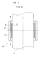
- a conventional foil bearing apparatus 50 includes a rotational shaft 51, a foil 52 which is wound on the outer periphery of the rotational shaft 51 plural times, and a bearing outer ring 53 which is disposed in the outer periphery of the foil 52. Both ends of the bearing outer ring 53 are provided with a pair of stoppers 54 and 54 so as to prevent the foil 52 from protruding in the axial direction.
- the foil bearing apparatus 50 When the rotational shaft 51 is rotated, an air layer is formed between the rotational shaft 51 and the foil 52.
- the foil bearing apparatus 50 rotatably supports the rotational shaft 51 without using oil.
- both axial displacements of the outer peripheral side 52b of the foil 52 are regulated by stoppers 54 and 54. Accordingly, it is possible to prevent a problem caused by the axial displacement of the outer peripheral side 52b of the foil 52.
- Patent Document 1 discloses a technology in which the stoppers 54 and 54 are formed in the bearing outer ring 53 so as to prevent the outer peripheral side 52b of the foil 52 from being displaced to protrude in the axial direction.
- the conventional foil bearing apparatus 50 it is possible to prevent the axial displacement of the outer peripheral side 52b of the foil 52, but it is not possible to prevent the axial displacement of the inner peripheral side 52a of the foil 52.
- the inner peripheral side 52a of the foil 52 corresponds to a position contacting with the rotation side (rotational shaft 51) and a surface forming an air layer. For this reason, when the inner peripheral side 52a of the foil 52 is displaced to protrude in the axial direction, the appropriate function of the bearing is disturbed, which may cause various problems (an increase in friction resistance at a bearing position, a damage of the rotational shaft 51, and the like).
- an object of the invention is to provide a foil bearing apparatus capable of preventing an axial displacement of an inner peripheral side of a foil.
- a foil bearing apparatus including: a rotational shaft; a foil which is disposed in the outer periphery of the rotational shaft; and a bearing outer ring which is disposed in the outer periphery of the foil, wherein a foil displacement regulating portion is provided so as to regulate an axial displacement of the inner peripheral side of the foil.
- the foil bearing apparatus further includes a bearing inner ring which is fixed to the outer periphery of the rotational shaft and supports the inner peripheral side of the foil, and the foil displacement regulating portion is formed in the bearing inner ring.
- the foil bearing apparatus further includes a bearing inner ring which is fixed to the outer periphery of the rotational shaft and supports the inner peripheral side of the foil, the foil displacement regulating portion is formed in both outsides of the foil, and the foil displacement regulating portions are respectively formed in the rotational shaft and the bearing inner ring.
- the foil displacement regulating portion is formed in the rotational shaft.
- the axial displacement of the inner peripheral side of the foil is regulated by the foil displacement regulating portion. Accordingly, it is possible to prevent a problem caused by the axial displacement of the inner peripheral side of the foil.
- the assembling workability is good compared with the conventional example. That is, in the conventional example, since a pair of stoppers is formed on the side of the bearing outer ring, the foil is disposed on the inner peripheral surface of the bearing outer ring. Subsequently, a conical jig of which large diameter side has the same diameter as that of the rotational shaft is attached to the end surface of the rotational shaft. Subsequently, the bearing outer ring and the foil are inserted into the rotational shaft from a small diameter side of the conical jig. Since the foil may be deviated to protrude during the inserting process, the assembling workability is poor.
- the bearing inner ring is provided with the foil displacement regulating portion, the foil is temporarily assembled at the outer periphery of the bearing inner ring, and an operator inserts the bearing outer ring while pressing the foil toward the bearing inner ring so as to minimize the maximum outer diameter. Since it is possible to press the foil by using a finger even when the outer diameter of the bearing inner ring is small, the assembling workability is good.
- the shape of the end surface of the rotational shaft is limited.
- the shape of the end surface of the rotational shaft is not limited.
- the assembling workability is good compared with the conventional example due to the same reason as that of the invention according to claim 1.
- the assembling workability is good compared with the conventional example due to the same reason as that of the invention according to claim 1.
- Figs. 2 and 3 show the first embodiment of the invention.
- Fig. 2 is a sectional view showing a foil bearing apparatus
- Fig. 3 is a sectional view taken along the line A-A in Fig. 2 .
- a foil bearing apparatus 1A includes a rotational shaft 2 which is rotated at a high speed by driving means (not shown); a bearing inner ring 3 which is pressed into the outer periphery of the rotational shaft 2; a foil 4 which is disposed in the outer periphery of the bearing inner ring 3; and a bearing outer ring 5 which is disposed in the outer periphery of the foil 4.
- the bearing inner ring 3 includes an outer peripheral surface 3a which comes into contact with an inner peripheral side 4a of the foil 4; and a pair of foil displacement regulating portions 6 and 7 which protrudes outward more than the outer peripheral surface 3a.
- a width between the pair of foil displacement regulating portions 6 and 7 is set to be slightly wider than that of the foil 4.
- Each of the foil displacement regulating portions 6 and 7 is set to have a height capable of regulating the axial displacement of the inner peripheral side 4a of the foil 4.
- the foil 4 is a thin metallic film, and may have various structures.
- the foil 4 may be made by laminating a flat foil on a wave-form-shaped foil, or made by winding one sheet of foil onto a shaft plural times.
- the bearing outer ring 5 is formed in a cylindrical shape, and the inner peripheral surface thereof comes into contact with the outer peripheral side 4b of the foil 4.
- the bearing outer ring 5 is fitted into, for example, a housing (not shown), which is a fixed portion relative to the rotational shaft 2, so as to have a gap therebetween, and is held by a rotation pin or the like so as not to be rotated.
- the foil bearing apparatus 1A rotatably supports the rotational shaft without using oil.
- both axial displacements of the inner peripheral side 4a of the foil 4 are regulated by the pair of foil displacement regulating portions 6 and 7. Accordingly, it is possible to prevent such problems that the friction resistance at the bearing position increases due to the axial displacement of the inner peripheral side 4a of the foil 4, and the rotational shaft 2 is damaged.
- the rotational shaft 2 is not damaged by the interference with the foil 4. Accordingly, a member which is damaged by the interference with the foil 4 is the bearing inner ring 3, the exchange workability of the bearing inner ring 3 is good, and the exchange cost thereof is low compared with the case of exchanging the rotational shaft 2.
- the assembling workability is good compared with the conventional example. That is, in the conventional example, since a pair of stoppers is formed on the side of the bearing outer ring, the foil is disposed on the inner peripheral surface of the bearing outer ring. Subsequently, a conical jig of which large diameter side has the same diameter as that of the rotational shaft is attached to the end surface of the rotational shaft. Subsequently, the bearing outer ring and the foil are inserted into the rotational shaft from a small diameter side of the conical jig. Since the foil may be deviated to protrude during the inserting process, the assembling workability is poor.
- the bearing inner ring 3 is provided with the foil displacement regulating portions 6 and 7, the foil 4 is temporarily assembled at the outer peripheral surface 3a of the bearing inner ring 3, and an operator inserts the bearing outer ring 5 while pressing the foil 4 toward the bearing inner ring 3 so as to minimize the maximum outer diameter. Since it is possible to press the foil 4 by using a finger even when the outer diameter of the bearing inner ring 3 is small, the assembling workability is good.
- the shape of the end surface of the rotational shaft is limited.
- the shape of the end surface of the rotational shaft 2 is not limited.
- the surfaces of the bearing inner ring 3 and the bearing outer ring 5 which may contact with the foil 4 may be coated with a fluorine resin or the like so as to improve the damage resistance.
- Fig. 4 is a sectional view showing the foil bearing apparatus according to the second embodiment of the invention.
- a foil bearing apparatus 1B includes a rotational shaft 10 which is rotated at a high speed by driving means (not shown); a bearing inner ring 11 which is pressed into the outer periphery of the rotational shaft 10; a foil 4 which is disposed in the outer periphery of the bearing inner ring 11; and a bearing outer ring 5 which is disposed in the outer periphery of the foil 4.
- the rotational shaft 10 is formed as a stepped shaft including a small diameter portion 10a and a large diameter portion 10b.
- a stepped surface 10c is formed in the boundary between the small diameter portion 10a and the large diameter portion 10b.
- the bearing inner ring 11 is pressed into the small diameter portion 10a of the rotational shaft 10.
- the bearing inner ring 11 includes an outer peripheral surface 11a which comes into contact with the inner peripheral side 4a of the foil 4, and one foil displacement regulation portion 16 which protrudes from one end of the outer peripheral surface 11a.
- the pressed front end surface of the bearing inner ring 11 comes into contact with the stepped surface 10c between the small diameter portion 10a and the large diameter portion 10b.
- the diameter of the outer peripheral surface 11a of the bearing inner ring 11 is set to be smaller than that of the large diameter portion 10b of the rotational shaft 10. Accordingly, the end of the large diameter portion 10b of the rotational shaft 10 is formed as the other foil displacement regulation portion 17.
- the foil displacement regulating portions 16 and 17 are respectively provided in the bearing inner ring 11 and the rotational shaft 10.
- bearing outer ring 5 Since the bearing outer ring 5 is the same as that of the first embodiment, the description thereof will be omitted.
- both axial displacements of the inner peripheral side 4a of the foil 4 are regulated by the pair of foil displacement regulating portions 16 and 17 by the same effect as that of the first embodiment. Accordingly, it is possible to prevent a problem caused by the axial displacement of the inner peripheral side 4a of the foil 4.
- the inner peripheral side 4a of the foil 4 contacts with the bearing inner ring 11, but does not contact with the rotational shaft 10 when the rotation is stopped, it is possible to maximally prevent the rotational shaft 10 from being damaged by the interference with the foil 4. Accordingly, a member which is damaged by the interference with the foil 4 is the bearing inner ring 11 in most of cases, the exchange workability of the bearing inner ring 11 is good, and the exchange cost thereof is low compared with the case of exchanging the rotational shaft 10.
- the assembling workability is good compared with the conventional example. That is, in the second embodiment, since the bearing inner ring 11 and the rotational shaft 10 are provided with the foil regulating portions 16 and 17, the foil 4 is temporarily assembled at the outer peripheral surface 11a of the bearing inner ring 11, and the operator inserts the bearing outer ring 5 while pressing the foil 4 toward the bearing inner ring 11 so as to minimize the maximum outer diameter. Since it is possible to press the foil 4 by using a finger even when the outer diameter of the bearing inner ring 11 is small, the assembling workability is good.
- the surfaces of the rotational shaft 10, the bearing inner ring 11, and the bearing outer ring 5 which may contact with the foil 4 may be subjected to coating using a fluorine resin or the like so as to improve the damage resistance.
- Fig. 5 is a sectional view showing the foil bearing apparatus according to the third embodiment of the invention.
- a foil bearing apparatus 1C includes a rotational shaft 20 which is rotated at a high speed by driving means (not shown); a foil 4 which is disposed in the outer periphery of the rotational shaft 20; and a bearing outer ring 5 which is disposed in the outer periphery of the foil 4.
- the rotational shaft 20 is formed as a shaft provided with a groove formed by a small diameter portion 20a and both-side large diameter portions 20b and 20b. Stepped surfaces 20c and 20c are respectively formed in the boundaries between the small diameter portion 20a and both-side large diameter portions 20b and 20b.
- the foil 4 is disposed in the outer periphery of the small diameter portion 20a of the rotational shaft 20. Accordingly, the large diameter portions 20b and 20b of the rotational shaft 20 are respectively disposed on the outside of both ends of the foil 4. The ends of both-side large diameter portions 20b and 20b are formed as a pair of foil displacement regulating portions 21 and 22. Since the configuration of the foil 4 is the same as that of the first embodiment, the description thereof will be omitted.
- both axial displacements of the inner peripheral side 4a of the foil 4 are regulated by the pair of foil displacement regulating portions 21 and 22 by the same effect as that of the first embodiment. Accordingly, it is possible to prevent a problem caused by the axial displacement of the inner peripheral side 4a of the foil 4.
- the foil bearing apparatus 1C since the foil bearing apparatus 1C includes the rotational shaft 20, the foil 4, and the bearing outer ring 5, it is possible to prevent the axial displacement of the inner peripheral side 4a of the foil 4 without increasing the number of components compared with the conventional example.
- the assembling workability is good compared with the conventional example. That is, in the third embodiment, since the rotational shaft 20 is provided with the foil regulating portions 21 and 22, the foil 4 is temporarily assembled at the outer periphery of the small diameter portion 20a of the rotational shaft 20, and the operator inserts the bearing outer ring 5 while pressing the foil 4 toward the rotational shaft 20 so as to minimize the maximum outer diameter. Since it is possible to press the foil 4 by using a finger even when the outer diameter of the rotational shaft 20 is small, the assembling workability is good.
- the surfaces of the rotational shaft 20 and the bearing outer ring 5 which may contact with the foil 4 may be coated with a fluorine resin or the like so as to improve the damage resistance.
- the bearing outer ring 5 may be, of course, provided with the foil outside displacement regulation portion which regulates the axial displacement of the outer peripheral side 4b of the foil 4.
- the foil outside displacement regulation portion is provided, it is possible to prevent the axial displacement of the outer peripheral side 4b as well as the inner peripheral side 4a of the foil 4.
- the foil 4 may be of various types. That is, there are a multiple wound foil in which an elongate band-shaped plate member is wound multiple times, a bump foil which is formed by a top foil and a bump foil, a leaf foil which is formed by plural foil pieces, and the like. Of course, the invention may be applied to any foil of them.
Landscapes
- Engineering & Computer Science (AREA)
- General Engineering & Computer Science (AREA)
- Physics & Mathematics (AREA)
- Fluid Mechanics (AREA)
- Mechanical Engineering (AREA)
- Support Of The Bearing (AREA)
Abstract
Description
- The present invention relates to a foil bearing apparatus which includes a thin plate-shaped foil disposed in the outer periphery of a rotational shaft, and a bearing outer ring disposed in the outer periphery of the foil, and which rotatably supports the rotational shaft without oil by forming an air layer between the rotating rotational shaft and the foil.
- Since this kind of foil bearing apparatus is capable of supporting a rotational shaft rotating at a high speed without supplying oil, the bearing apparatus is suitably used in a turbo compressor, a turbo charger, a gas turbine, and the like.
- As shown in
Fig. 1 , a conventionalfoil bearing apparatus 50 includes arotational shaft 51, afoil 52 which is wound on the outer periphery of therotational shaft 51 plural times, and a bearingouter ring 53 which is disposed in the outer periphery of thefoil 52. Both ends of the bearingouter ring 53 are provided with a pair ofstoppers foil 52 from protruding in the axial direction. - When the
rotational shaft 51 is rotated, an air layer is formed between therotational shaft 51 and thefoil 52. By using the air layer as a lubricating layer, thefoil bearing apparatus 50 rotatably supports therotational shaft 51 without using oil. In addition, when an outerperipheral side 52b of thefoil 52 is about to be displaced in the axial direction by the disturbance or the like, both axial displacements of the outerperipheral side 52b of thefoil 52 are regulated bystoppers peripheral side 52b of thefoil 52. - In addition,
Patent Document 1 discloses a technology in which thestoppers outer ring 53 so as to prevent the outerperipheral side 52b of thefoil 52 from being displaced to protrude in the axial direction. - [Patent Document 1] Japanese Patent Application Laid-Open No.
S63-47520 - In the conventional
foil bearing apparatus 50, it is possible to prevent the axial displacement of the outerperipheral side 52b of thefoil 52, but it is not possible to prevent the axial displacement of the innerperipheral side 52a of thefoil 52. The innerperipheral side 52a of thefoil 52 corresponds to a position contacting with the rotation side (rotational shaft 51) and a surface forming an air layer. For this reason, when the innerperipheral side 52a of thefoil 52 is displaced to protrude in the axial direction, the appropriate function of the bearing is disturbed, which may cause various problems (an increase in friction resistance at a bearing position, a damage of therotational shaft 51, and the like). - Therefore, the invention is contrived to solve the above-described problems, and an object of the invention is to provide a foil bearing apparatus capable of preventing an axial displacement of an inner peripheral side of a foil.
- According to the invention of
claim 1, there is provided a foil bearing apparatus including: a rotational shaft; a foil which is disposed in the outer periphery of the rotational shaft; and a bearing outer ring which is disposed in the outer periphery of the foil, wherein a foil displacement regulating portion is provided so as to regulate an axial displacement of the inner peripheral side of the foil. - According to the invention of
claim 2, in the foil bearing apparatus ofclaim 1, the foil bearing apparatus further includes a bearing inner ring which is fixed to the outer periphery of the rotational shaft and supports the inner peripheral side of the foil, and the foil displacement regulating portion is formed in the bearing inner ring. - According to the invention of
claim 3, in the foil bearing apparatus ofclaim 1, the foil bearing apparatus further includes a bearing inner ring which is fixed to the outer periphery of the rotational shaft and supports the inner peripheral side of the foil, the foil displacement regulating portion is formed in both outsides of the foil, and the foil displacement regulating portions are respectively formed in the rotational shaft and the bearing inner ring. - According to the invention of
claim 4, in the foil bearing apparatus ofclaim 1, the foil displacement regulating portion is formed in the rotational shaft. - In the invention according to
claim 1, when the inner peripheral side of the foil is about to be displaced in the axial direction by the disturbance or the like, the axial displacement of the inner peripheral side of the foil is regulated by the foil displacement regulating portion. Accordingly, it is possible to prevent a problem caused by the axial displacement of the inner peripheral side of the foil. - In the invention according to
claim 2, in addition to the advantage of the invention according toclaim 1, since the inner peripheral side of the foil contacts with the bearing inner ring when the rotation is stopped, but does not contact with the rotational shaft, the rotational shaft is not damaged by the interference with the foil. Accordingly, a member which may be damaged by the interference with the foil is the bearing inner ring, the exchange workability of the bearing inner ring is good, and the exchange cost thereof is low compared with the case of exchanging the rotational shaft. - Further, in the foil bearing apparatus, the assembling workability is good compared with the conventional example. That is, in the conventional example, since a pair of stoppers is formed on the side of the bearing outer ring, the foil is disposed on the inner peripheral surface of the bearing outer ring. Subsequently, a conical jig of which large diameter side has the same diameter as that of the rotational shaft is attached to the end surface of the rotational shaft. Subsequently, the bearing outer ring and the foil are inserted into the rotational shaft from a small diameter side of the conical jig. Since the foil may be deviated to protrude during the inserting process, the assembling workability is poor. On the contrary, in the embodiment, since the bearing inner ring is provided with the foil displacement regulating portion, the foil is temporarily assembled at the outer periphery of the bearing inner ring, and an operator inserts the bearing outer ring while pressing the foil toward the bearing inner ring so as to minimize the maximum outer diameter. Since it is possible to press the foil by using a finger even when the outer diameter of the bearing inner ring is small, the assembling workability is good.
- In the conventional example, since it is necessary to attach the jig to the end surface of the rotational shaft in the assembling process, the shape of the end surface of the rotational shaft is limited. On the contrary, in the embodiment, since it is not necessary to use the jig in the assembling process, the shape of the end surface of the rotational shaft is not limited.
- In the invention according to
claim 3, in addition to the advantage of the invention according toclaim 1, since the inner peripheral side of the foil contacts with the bearing inner ring when the rotation is stopped, but does not contact with the rotational shaft, it is possible to maximally prevent the rotational shaft from being damaged by the interference with the foil. Accordingly, a member which may be damaged by the interference with the foil is the bearing inner ring in most of cases, the exchange workability of the bearing inner ring is good, and the exchange cost thereof is low compared with the case of exchanging the rotational shaft. - Further, in the foil bearing apparatus, the assembling workability is good compared with the conventional example due to the same reason as that of the invention according to
claim 1. - In the invention according to
claim 4, in addition to the advantage of the invention according toclaim 1, the number of components does not increase. - Furthermore, in the foil bearing apparatus, the assembling workability is good compared with the conventional example due to the same reason as that of the invention according to
claim 1. -
-
Fig. 1 is a sectional view showing a conventional foil bearing apparatus. -
Fig. 2 is a sectional view showing the foil bearing apparatus according to the first embodiment of the invention. -
Fig. 3 is a sectional view taken along the line A-A inFig. 2 according to the first embodiment of the invention. -
Fig. 4 is a sectional view showing the foil bearing apparatus according to the second embodiment of the invention. -
Fig. 5 is a sectional view showing the foil bearing apparatus according to the third embodiment of the invention. - Hereinafter, the exemplary embodiments of the invention will be described with reference to the drawings.
-
Figs. 2 and3 show the first embodiment of the invention.Fig. 2 is a sectional view showing a foil bearing apparatus, andFig. 3 is a sectional view taken along the line A-A inFig. 2 . - As shown in
Figs. 2 and3 , afoil bearing apparatus 1A includes arotational shaft 2 which is rotated at a high speed by driving means (not shown); a bearinginner ring 3 which is pressed into the outer periphery of therotational shaft 2; afoil 4 which is disposed in the outer periphery of the bearinginner ring 3; and a bearingouter ring 5 which is disposed in the outer periphery of thefoil 4. - The bearing
inner ring 3 includes an outerperipheral surface 3a which comes into contact with an innerperipheral side 4a of thefoil 4; and a pair of foil displacement regulating portions 6 and 7 which protrudes outward more than the outerperipheral surface 3a. - A width between the pair of foil displacement regulating portions 6 and 7 is set to be slightly wider than that of the
foil 4. Each of the foil displacement regulating portions 6 and 7 is set to have a height capable of regulating the axial displacement of the innerperipheral side 4a of thefoil 4. - The
foil 4 is a thin metallic film, and may have various structures. As a detailed example, thefoil 4 may be made by laminating a flat foil on a wave-form-shaped foil, or made by winding one sheet of foil onto a shaft plural times. - The bearing
outer ring 5 is formed in a cylindrical shape, and the inner peripheral surface thereof comes into contact with the outerperipheral side 4b of thefoil 4. The bearingouter ring 5 is fitted into, for example, a housing (not shown), which is a fixed portion relative to therotational shaft 2, so as to have a gap therebetween, and is held by a rotation pin or the like so as not to be rotated. - In the above-described configuration, when the
rotational shaft 2 is rotated, an air layer is formed between the bearinginner ring 3 and thefoil 4. By using the air layer as a lubricating layer, thefoil bearing apparatus 1A rotatably supports the rotational shaft without using oil. In addition, when the innerperipheral side 4a of thefoil 4 is about to be displaced in the axial direction by the disturbance or the like, both axial displacements of the innerperipheral side 4a of thefoil 4 are regulated by the pair of foil displacement regulating portions 6 and 7. Accordingly, it is possible to prevent such problems that the friction resistance at the bearing position increases due to the axial displacement of the innerperipheral side 4a of thefoil 4, and therotational shaft 2 is damaged. - In the first embodiment, since the inner
peripheral side 4a of thefoil 4 contacts with the bearinginner ring 3, but does not contact with therotational shaft 2, therotational shaft 2 is not damaged by the interference with thefoil 4. Accordingly, a member which is damaged by the interference with thefoil 4 is the bearinginner ring 3, the exchange workability of the bearinginner ring 3 is good, and the exchange cost thereof is low compared with the case of exchanging therotational shaft 2. - Further, in the
foil bearing apparatus 1A according to the first embodiment, the assembling workability is good compared with the conventional example. That is, in the conventional example, since a pair of stoppers is formed on the side of the bearing outer ring, the foil is disposed on the inner peripheral surface of the bearing outer ring. Subsequently, a conical jig of which large diameter side has the same diameter as that of the rotational shaft is attached to the end surface of the rotational shaft. Subsequently, the bearing outer ring and the foil are inserted into the rotational shaft from a small diameter side of the conical jig. Since the foil may be deviated to protrude during the inserting process, the assembling workability is poor. On the contrary, in the first embodiment, since the bearinginner ring 3 is provided with the foil displacement regulating portions 6 and 7, thefoil 4 is temporarily assembled at the outerperipheral surface 3a of the bearinginner ring 3, and an operator inserts the bearingouter ring 5 while pressing thefoil 4 toward the bearinginner ring 3 so as to minimize the maximum outer diameter. Since it is possible to press thefoil 4 by using a finger even when the outer diameter of the bearinginner ring 3 is small, the assembling workability is good. - In the conventional example, since it is necessary to attach the jig to the end surface of the rotational shaft in the assembling process, the shape of the end surface of the rotational shaft is limited. On the contrary, in the first embodiment, since it is not necessary to use the jig in the assembling process, the shape of the end surface of the
rotational shaft 2 is not limited. - Further, in the first embodiment, the surfaces of the bearing
inner ring 3 and the bearingouter ring 5 which may contact with thefoil 4 may be coated with a fluorine resin or the like so as to improve the damage resistance. -
Fig. 4 is a sectional view showing the foil bearing apparatus according to the second embodiment of the invention. - As shown in
Fig. 4 , afoil bearing apparatus 1B includes arotational shaft 10 which is rotated at a high speed by driving means (not shown); a bearinginner ring 11 which is pressed into the outer periphery of therotational shaft 10; afoil 4 which is disposed in the outer periphery of the bearinginner ring 11; and a bearingouter ring 5 which is disposed in the outer periphery of thefoil 4. - The
rotational shaft 10 is formed as a stepped shaft including asmall diameter portion 10a and alarge diameter portion 10b. A steppedsurface 10c is formed in the boundary between thesmall diameter portion 10a and thelarge diameter portion 10b. - The bearing
inner ring 11 is pressed into thesmall diameter portion 10a of therotational shaft 10. The bearinginner ring 11 includes an outerperipheral surface 11a which comes into contact with the innerperipheral side 4a of thefoil 4, and one foildisplacement regulation portion 16 which protrudes from one end of the outerperipheral surface 11a. The pressed front end surface of the bearinginner ring 11 comes into contact with the steppedsurface 10c between thesmall diameter portion 10a and thelarge diameter portion 10b. The diameter of the outerperipheral surface 11a of the bearinginner ring 11 is set to be smaller than that of thelarge diameter portion 10b of therotational shaft 10. Accordingly, the end of thelarge diameter portion 10b of therotational shaft 10 is formed as the other foildisplacement regulation portion 17. - That is, in the second embodiment, the foil
displacement regulating portions inner ring 11 and therotational shaft 10. - Since the
foil 4 is the same as that of the first embodiment, the description thereof will be omitted. - Since the bearing
outer ring 5 is the same as that of the first embodiment, the description thereof will be omitted. - Even in the second embodiment, both axial displacements of the inner
peripheral side 4a of thefoil 4 are regulated by the pair of foildisplacement regulating portions peripheral side 4a of thefoil 4. - In the second embodiment, since the inner
peripheral side 4a of thefoil 4 contacts with the bearinginner ring 11, but does not contact with therotational shaft 10 when the rotation is stopped, it is possible to maximally prevent therotational shaft 10 from being damaged by the interference with thefoil 4. Accordingly, a member which is damaged by the interference with thefoil 4 is the bearinginner ring 11 in most of cases, the exchange workability of the bearinginner ring 11 is good, and the exchange cost thereof is low compared with the case of exchanging therotational shaft 10. - Additionally, even in the
foil bearing apparatus 1B according to the second embodiment, the assembling workability is good compared with the conventional example. That is, in the second embodiment, since the bearinginner ring 11 and therotational shaft 10 are provided with thefoil regulating portions foil 4 is temporarily assembled at the outerperipheral surface 11a of the bearinginner ring 11, and the operator inserts the bearingouter ring 5 while pressing thefoil 4 toward the bearinginner ring 11 so as to minimize the maximum outer diameter. Since it is possible to press thefoil 4 by using a finger even when the outer diameter of the bearinginner ring 11 is small, the assembling workability is good. - Further, in the second embodiment, the surfaces of the
rotational shaft 10, the bearinginner ring 11, and the bearingouter ring 5 which may contact with thefoil 4 may be subjected to coating using a fluorine resin or the like so as to improve the damage resistance. -
Fig. 5 is a sectional view showing the foil bearing apparatus according to the third embodiment of the invention. - As shown in
Fig. 5 , afoil bearing apparatus 1C includes arotational shaft 20 which is rotated at a high speed by driving means (not shown); afoil 4 which is disposed in the outer periphery of therotational shaft 20; and a bearingouter ring 5 which is disposed in the outer periphery of thefoil 4. - The
rotational shaft 20 is formed as a shaft provided with a groove formed by asmall diameter portion 20a and both-sidelarge diameter portions surfaces small diameter portion 20a and both-sidelarge diameter portions - The
foil 4 is disposed in the outer periphery of thesmall diameter portion 20a of therotational shaft 20. Accordingly, thelarge diameter portions rotational shaft 20 are respectively disposed on the outside of both ends of thefoil 4. The ends of both-sidelarge diameter portions displacement regulating portions foil 4 is the same as that of the first embodiment, the description thereof will be omitted. - Since the configuration of the bearing
outer ring 5 is the same as that of the first embodiment, the description thereof will be omitted. - Even in the third embodiment, both axial displacements of the inner
peripheral side 4a of thefoil 4 are regulated by the pair of foildisplacement regulating portions peripheral side 4a of thefoil 4. - In the third embodiment, since the
foil bearing apparatus 1C includes therotational shaft 20, thefoil 4, and the bearingouter ring 5, it is possible to prevent the axial displacement of the innerperipheral side 4a of thefoil 4 without increasing the number of components compared with the conventional example. - Further, even in the
foil bearing apparatus 1C according to the third embodiment, the assembling workability is good compared with the conventional example. That is, in the third embodiment, since therotational shaft 20 is provided with thefoil regulating portions foil 4 is temporarily assembled at the outer periphery of thesmall diameter portion 20a of therotational shaft 20, and the operator inserts the bearingouter ring 5 while pressing thefoil 4 toward therotational shaft 20 so as to minimize the maximum outer diameter. Since it is possible to press thefoil 4 by using a finger even when the outer diameter of therotational shaft 20 is small, the assembling workability is good. - Furthermore, in the third embodiment, the surfaces of the
rotational shaft 20 and the bearingouter ring 5 which may contact with thefoil 4 may be coated with a fluorine resin or the like so as to improve the damage resistance. - In the above-described embodiments, as in the conventional example, the bearing
outer ring 5 may be, of course, provided with the foil outside displacement regulation portion which regulates the axial displacement of the outerperipheral side 4b of thefoil 4. When the foil outside displacement regulation portion is provided, it is possible to prevent the axial displacement of the outerperipheral side 4b as well as the innerperipheral side 4a of thefoil 4. - Further, as described above, the
foil 4 may be of various types. That is, there are a multiple wound foil in which an elongate band-shaped plate member is wound multiple times, a bump foil which is formed by a top foil and a bump foil, a leaf foil which is formed by plural foil pieces, and the like. Of course, the invention may be applied to any foil of them.
Claims (4)
- A foil bearing apparatus comprising:a rotational shaft;a foil which is disposed in the outer periphery of the rotational shaft; anda bearing outer ring which is disposed in the outer periphery of the foil,wherein a foil displacement regulating portion is provided so as to regulate an axial displacement of the inner peripheral side of the foil.
- The foil bearing apparatus according to claim 1, further comprising:a bearing inner ring which is fixed to the outer periphery of the rotational shaft and supports the inner peripheral side of the foil,wherein the foil displacement regulating portion is formed in the bearing inner ring.
- The foil bearing apparatus according to claim 1, further comprising:a bearing inner ring which is fixed to the outer periphery of the rotational shaft and supports the inner peripheral side of the foil,wherein the foil displacement regulating portion is formed in both outsides of the foil, andwherein the foil displacement regulating portions are respectively formed in the rotational shaft and the bearing inner ring.
- The foil bearing apparatus according to claim 1,
wherein the foil displacement regulating portion is formed in the rotational shaft.
Applications Claiming Priority (2)
| Application Number | Priority Date | Filing Date | Title |
|---|---|---|---|
| JP2007209976A JP2009041736A (en) | 2007-08-10 | 2007-08-10 | Foil bearing device |
| PCT/JP2008/059729 WO2009022487A1 (en) | 2007-08-10 | 2008-05-27 | Foil bearing device |
Publications (2)
| Publication Number | Publication Date |
|---|---|
| EP2175150A1 true EP2175150A1 (en) | 2010-04-14 |
| EP2175150A4 EP2175150A4 (en) | 2011-12-21 |
Family
ID=40350545
Family Applications (1)
| Application Number | Title | Priority Date | Filing Date |
|---|---|---|---|
| EP08764757A Withdrawn EP2175150A4 (en) | 2007-08-10 | 2008-05-27 | Foil bearing device |
Country Status (8)
| Country | Link |
|---|---|
| US (1) | US20110211783A1 (en) |
| EP (1) | EP2175150A4 (en) |
| JP (1) | JP2009041736A (en) |
| KR (1) | KR20100039844A (en) |
| CN (1) | CN101796314A (en) |
| AU (1) | AU2008288037A1 (en) |
| CA (1) | CA2692510A1 (en) |
| WO (1) | WO2009022487A1 (en) |
Families Citing this family (8)
| Publication number | Priority date | Publication date | Assignee | Title |
|---|---|---|---|---|
| JP5286955B2 (en) | 2008-06-12 | 2013-09-11 | 株式会社Ihi | Foil bearing |
| US9033657B2 (en) | 2011-12-12 | 2015-05-19 | Honeywell International Inc. | Gas turbine engine including lift-off finger seals, lift-off finger seals, and method for the manufacture thereof |
| US9506566B2 (en) | 2013-10-23 | 2016-11-29 | Honeywell International Inc. | Finger-foil seals and gas turbine engines employing the same |
| CN106640967B (en) * | 2016-12-05 | 2018-11-20 | 南京圣威惠众机电技术有限公司 | A kind of gas foil bearing of horizontal online adjustable clearance |
| KR102463189B1 (en) * | 2017-08-23 | 2022-11-03 | 현대자동차 주식회사 | Air foil bearing assembly |
| JP7027968B2 (en) * | 2018-03-07 | 2022-03-02 | 株式会社Ihi | Radial foil bearing |
| CN109296561A (en) * | 2018-09-07 | 2019-02-01 | 上海新时达电气股份有限公司 | A bearing and a fan |
| KR102187666B1 (en) * | 2019-09-02 | 2020-12-07 | 주식회사 뉴로스 | Air foil journal bearing |
Family Cites Families (17)
| Publication number | Priority date | Publication date | Assignee | Title |
|---|---|---|---|---|
| US2738241A (en) * | 1952-07-16 | 1956-03-13 | Firm Kugelfischer Georg Schafe | Hydrodynamic bearing |
| US2897026A (en) * | 1955-06-13 | 1959-07-28 | Halex Corp | Expansion compensating sleeve bearing unit |
| US3215480A (en) * | 1963-08-29 | 1965-11-02 | David J Marley | Hydrodynamic foil bearings with bearing foil retaining means |
| US3765732A (en) * | 1972-02-28 | 1973-10-16 | G Watt | Outlet restrictor hydrostatic bearing |
| US3884534A (en) * | 1974-04-09 | 1975-05-20 | Mechanical Tech Inc | Increased damping hydrodynamic foil bearing |
| JPS5717131Y2 (en) * | 1977-07-26 | 1982-04-09 | ||
| JPS5471043U (en) * | 1977-10-28 | 1979-05-21 | ||
| JPS54143985U (en) * | 1978-03-30 | 1979-10-05 | ||
| US4222618A (en) * | 1978-12-29 | 1980-09-16 | Mechanical Technology Incorporated | Compliant hydrodynamic fluid bearing with resilient support matrix |
| DE2934271C2 (en) * | 1979-08-24 | 1983-11-10 | MTU Motoren- und Turbinen-Union München GmbH, 8000 München | Aerodynamic radial bearing for high-speed flow machines |
| JPS57171423U (en) * | 1981-04-23 | 1982-10-28 | ||
| JPH0615132Y2 (en) * | 1986-12-01 | 1994-04-20 | 光洋精工株式会社 | Ceramic radial type full ball bearing device for molten metal plating tank |
| JPH06347520A (en) | 1993-06-04 | 1994-12-22 | Hitachi Ltd | Delay test method |
| JP4225006B2 (en) * | 2002-08-21 | 2009-02-18 | 日本精工株式会社 | Double row angular contact ball bearings for wheels |
| JP2006112568A (en) * | 2004-10-15 | 2006-04-27 | Nsk Ltd | Cylindrical roller bearing |
| JP2006312955A (en) * | 2005-05-06 | 2006-11-16 | Nsk Ltd | Rolling bearing |
| JP2006349031A (en) * | 2005-06-15 | 2006-12-28 | Nsk Ltd | Tapered roller bearings |
-
2007
- 2007-08-10 JP JP2007209976A patent/JP2009041736A/en active Pending
-
2008
- 2008-05-27 US US12/673,460 patent/US20110211783A1/en not_active Abandoned
- 2008-05-27 KR KR1020107000543A patent/KR20100039844A/en not_active Ceased
- 2008-05-27 AU AU2008288037A patent/AU2008288037A1/en not_active Abandoned
- 2008-05-27 WO PCT/JP2008/059729 patent/WO2009022487A1/en not_active Ceased
- 2008-05-27 CN CN200880102907.1A patent/CN101796314A/en active Pending
- 2008-05-27 EP EP08764757A patent/EP2175150A4/en not_active Withdrawn
- 2008-05-27 CA CA 2692510 patent/CA2692510A1/en not_active Abandoned
Also Published As
| Publication number | Publication date |
|---|---|
| EP2175150A4 (en) | 2011-12-21 |
| JP2009041736A (en) | 2009-02-26 |
| CN101796314A (en) | 2010-08-04 |
| WO2009022487A1 (en) | 2009-02-19 |
| AU2008288037A1 (en) | 2009-02-19 |
| US20110211783A1 (en) | 2011-09-01 |
| KR20100039844A (en) | 2010-04-16 |
| CA2692510A1 (en) | 2009-02-19 |
Similar Documents
| Publication | Publication Date | Title |
|---|---|---|
| US20110211783A1 (en) | Foil bearing apparatus | |
| EP2740949B1 (en) | Radial foil bearing | |
| US6519116B1 (en) | Actuator arm assembly having bearing gap formed between bearing outer race and pivot sleeve for mitigating torque ripple on actuator arm in a disk drive | |
| EP3002471B1 (en) | Radial foil bearing | |
| EP2142816B1 (en) | Mounting assembly | |
| US6933649B2 (en) | Method of installation of a laminated stator core stack in the motor casing | |
| EP2287479A1 (en) | Foil bearing | |
| WO2012127998A1 (en) | Foil bearing and manufacturing method therefor | |
| JP2013192363A (en) | Insulation sheet manufacturing method and insulation sheet manufacturing apparatus | |
| EP3369951A1 (en) | Thrust foil bearing | |
| EP3647612A1 (en) | Radial foil bearing | |
| EP2098738B1 (en) | Thrust roller bearing | |
| EP3763956A1 (en) | Radial foil bearing | |
| US11092192B2 (en) | Radial foil bearing | |
| JPS63195412A (en) | Leaf type foil thrust bearing | |
| KR20200108438A (en) | Press apparatus having a rotation lamination mold and a rotation lamination mold | |
| US11293482B2 (en) | Radial foil bearing | |
| JP6740145B2 (en) | Flat wire bending device | |
| US20230313831A1 (en) | Radial air bearing device and method for producing a radial air bearing device | |
| JP2012121648A (en) | Conveying roller and printing device | |
| JP2005116039A (en) | Disk unit |
Legal Events
| Date | Code | Title | Description |
|---|---|---|---|
| PUAI | Public reference made under article 153(3) epc to a published international application that has entered the european phase |
Free format text: ORIGINAL CODE: 0009012 |
|
| 17P | Request for examination filed |
Effective date: 20100128 |
|
| AK | Designated contracting states |
Kind code of ref document: A1 Designated state(s): AT BE BG CH CY CZ DE DK EE ES FI FR GB GR HR HU IE IS IT LI LT LU LV MC MT NL NO PL PT RO SE SI SK TR |
|
| AX | Request for extension of the european patent |
Extension state: AL BA MK RS |
|
| DAX | Request for extension of the european patent (deleted) | ||
| A4 | Supplementary search report drawn up and despatched |
Effective date: 20111121 |
|
| RIC1 | Information provided on ipc code assigned before grant |
Ipc: F16C 27/02 20060101AFI20111115BHEP |
|
| STAA | Information on the status of an ep patent application or granted ep patent |
Free format text: STATUS: THE APPLICATION IS DEEMED TO BE WITHDRAWN |
|
| 18D | Application deemed to be withdrawn |
Effective date: 20120619 |