EP2174848A2 - Two plate manifold with crossovers - Google Patents
Two plate manifold with crossovers Download PDFInfo
- Publication number
- EP2174848A2 EP2174848A2 EP20090172312 EP09172312A EP2174848A2 EP 2174848 A2 EP2174848 A2 EP 2174848A2 EP 20090172312 EP20090172312 EP 20090172312 EP 09172312 A EP09172312 A EP 09172312A EP 2174848 A2 EP2174848 A2 EP 2174848A2
- Authority
- EP
- European Patent Office
- Prior art keywords
- plate
- passage
- chamber
- crossing
- crossover element
- Prior art date
- Legal status (The legal status is an assumption and is not a legal conclusion. Google has not performed a legal analysis and makes no representation as to the accuracy of the status listed.)
- Granted
Links
- 238000003801 milling Methods 0.000 claims description 17
- 238000000034 method Methods 0.000 claims description 14
- 238000004519 manufacturing process Methods 0.000 claims description 2
- 239000000853 adhesive Substances 0.000 description 5
- 230000001070 adhesive effect Effects 0.000 description 5
- 230000003137 locomotive effect Effects 0.000 description 3
- 239000007767 bonding agent Substances 0.000 description 2
- 239000012530 fluid Substances 0.000 description 2
- 230000008569 process Effects 0.000 description 2
- 230000008878 coupling Effects 0.000 description 1
- 238000010168 coupling process Methods 0.000 description 1
- 238000005859 coupling reaction Methods 0.000 description 1
- 230000001627 detrimental effect Effects 0.000 description 1
- 239000003292 glue Substances 0.000 description 1
- 230000006872 improvement Effects 0.000 description 1
- 230000004048 modification Effects 0.000 description 1
- 238000012986 modification Methods 0.000 description 1
- 238000012216 screening Methods 0.000 description 1
- 238000007789 sealing Methods 0.000 description 1
- 238000000926 separation method Methods 0.000 description 1
Images


Classifications
-
- B—PERFORMING OPERATIONS; TRANSPORTING
- B60—VEHICLES IN GENERAL
- B60T—VEHICLE BRAKE CONTROL SYSTEMS OR PARTS THEREOF; BRAKE CONTROL SYSTEMS OR PARTS THEREOF, IN GENERAL; ARRANGEMENT OF BRAKING ELEMENTS ON VEHICLES IN GENERAL; PORTABLE DEVICES FOR PREVENTING UNWANTED MOVEMENT OF VEHICLES; VEHICLE MODIFICATIONS TO FACILITATE COOLING OF BRAKES
- B60T17/00—Component parts, details, or accessories of power brake systems not covered by groups B60T8/00, B60T13/00 or B60T15/00, or presenting other characteristic features
- B60T17/04—Arrangements of piping, valves in the piping, e.g. cut-off valves, couplings or air hoses
-
- B—PERFORMING OPERATIONS; TRANSPORTING
- B60—VEHICLES IN GENERAL
- B60T—VEHICLE BRAKE CONTROL SYSTEMS OR PARTS THEREOF; BRAKE CONTROL SYSTEMS OR PARTS THEREOF, IN GENERAL; ARRANGEMENT OF BRAKING ELEMENTS ON VEHICLES IN GENERAL; PORTABLE DEVICES FOR PREVENTING UNWANTED MOVEMENT OF VEHICLES; VEHICLE MODIFICATIONS TO FACILITATE COOLING OF BRAKES
- B60T13/00—Transmitting braking action from initiating means to ultimate brake actuator with power assistance or drive; Brake systems incorporating such transmitting means, e.g. air-pressure brake systems
- B60T13/10—Transmitting braking action from initiating means to ultimate brake actuator with power assistance or drive; Brake systems incorporating such transmitting means, e.g. air-pressure brake systems with fluid assistance, drive, or release
- B60T13/66—Electrical control in fluid-pressure brake systems
- B60T13/665—Electrical control in fluid-pressure brake systems the systems being specially adapted for transferring two or more command signals, e.g. railway systems
-
- B—PERFORMING OPERATIONS; TRANSPORTING
- B60—VEHICLES IN GENERAL
- B60T—VEHICLE BRAKE CONTROL SYSTEMS OR PARTS THEREOF; BRAKE CONTROL SYSTEMS OR PARTS THEREOF, IN GENERAL; ARRANGEMENT OF BRAKING ELEMENTS ON VEHICLES IN GENERAL; PORTABLE DEVICES FOR PREVENTING UNWANTED MOVEMENT OF VEHICLES; VEHICLE MODIFICATIONS TO FACILITATE COOLING OF BRAKES
- B60T17/00—Component parts, details, or accessories of power brake systems not covered by groups B60T8/00, B60T13/00 or B60T15/00, or presenting other characteristic features
- B60T17/18—Safety devices; Monitoring
- B60T17/22—Devices for monitoring or checking brake systems; Signal devices
- B60T17/228—Devices for monitoring or checking brake systems; Signal devices for railway vehicles
-
- F—MECHANICAL ENGINEERING; LIGHTING; HEATING; WEAPONS; BLASTING
- F15—FLUID-PRESSURE ACTUATORS; HYDRAULICS OR PNEUMATICS IN GENERAL
- F15B—SYSTEMS ACTING BY MEANS OF FLUIDS IN GENERAL; FLUID-PRESSURE ACTUATORS, e.g. SERVOMOTORS; DETAILS OF FLUID-PRESSURE SYSTEMS, NOT OTHERWISE PROVIDED FOR
- F15B13/00—Details of servomotor systems ; Valves for servomotor systems
- F15B13/02—Fluid distribution or supply devices characterised by their adaptation to the control of servomotors
- F15B13/06—Fluid distribution or supply devices characterised by their adaptation to the control of servomotors for use with two or more servomotors
- F15B13/08—Assemblies of units, each for the control of a single servomotor only
- F15B13/0803—Modular units
- F15B13/0807—Manifolds
- F15B13/081—Laminated constructions
-
- Y—GENERAL TAGGING OF NEW TECHNOLOGICAL DEVELOPMENTS; GENERAL TAGGING OF CROSS-SECTIONAL TECHNOLOGIES SPANNING OVER SEVERAL SECTIONS OF THE IPC; TECHNICAL SUBJECTS COVERED BY FORMER USPC CROSS-REFERENCE ART COLLECTIONS [XRACs] AND DIGESTS
- Y10—TECHNICAL SUBJECTS COVERED BY FORMER USPC
- Y10T—TECHNICAL SUBJECTS COVERED BY FORMER US CLASSIFICATION
- Y10T137/00—Fluid handling
- Y10T137/7069—With lock or seal
- Y10T137/71—With seal
-
- Y—GENERAL TAGGING OF NEW TECHNOLOGICAL DEVELOPMENTS; GENERAL TAGGING OF CROSS-SECTIONAL TECHNOLOGIES SPANNING OVER SEVERAL SECTIONS OF THE IPC; TECHNICAL SUBJECTS COVERED BY FORMER USPC CROSS-REFERENCE ART COLLECTIONS [XRACs] AND DIGESTS
- Y10—TECHNICAL SUBJECTS COVERED BY FORMER USPC
- Y10T—TECHNICAL SUBJECTS COVERED BY FORMER US CLASSIFICATION
- Y10T137/00—Fluid handling
- Y10T137/8593—Systems
- Y10T137/877—With flow control means for branched passages
- Y10T137/87885—Sectional block structure
-
- Y—GENERAL TAGGING OF NEW TECHNOLOGICAL DEVELOPMENTS; GENERAL TAGGING OF CROSS-SECTIONAL TECHNOLOGIES SPANNING OVER SEVERAL SECTIONS OF THE IPC; TECHNICAL SUBJECTS COVERED BY FORMER USPC CROSS-REFERENCE ART COLLECTIONS [XRACs] AND DIGESTS
- Y10—TECHNICAL SUBJECTS COVERED BY FORMER USPC
- Y10T—TECHNICAL SUBJECTS COVERED BY FORMER US CLASSIFICATION
- Y10T29/00—Metal working
- Y10T29/49—Method of mechanical manufacture
- Y10T29/49428—Gas and water specific plumbing component making
-
- Y—GENERAL TAGGING OF NEW TECHNOLOGICAL DEVELOPMENTS; GENERAL TAGGING OF CROSS-SECTIONAL TECHNOLOGIES SPANNING OVER SEVERAL SECTIONS OF THE IPC; TECHNICAL SUBJECTS COVERED BY FORMER USPC CROSS-REFERENCE ART COLLECTIONS [XRACs] AND DIGESTS
- Y10—TECHNICAL SUBJECTS COVERED BY FORMER USPC
- Y10T—TECHNICAL SUBJECTS COVERED BY FORMER US CLASSIFICATION
- Y10T409/00—Gear cutting, milling, or planing
- Y10T409/30—Milling
- Y10T409/303752—Process
Definitions
- the present invention relates generally to pneumatic manifolds and more specifically to pneumatic manifolds for rail vehicle brakes.
- Manifolds for rail vehicle brakes include a plurality of faces having ports for connection to pneumatic devices, sources of pneumatic fluid and pneumatic circuits connected to the faces.
- pneumatic devices are mounted on the face and in other cases, the pneumatic devices, sources of pneumatic fluid and pneumatic circuits are connected to the device by hoses or other couplings.
- the manifold is mounted to the rail vehicle.
- the rail vehicle may include locomotives or cars including freight, passenger and mass transit.
- FIGS. 1-3 of US 5,803,124 One example of a prior art manifold, used for example in a freight locomotive known as CCB from New York Air Brake Corporation, is illustrated in FIGS. 1-3 of US 5,803,124 .
- the manifold includes two plates having the interior faces machine to provide passages and chambers and the exterior faces machine to have bores for connecting the passages and chambers to ports on the exterior faces.
- the passages are generally shallower than the chambers.
- Adhesives are applied to the interior faces to bond the two plates together. The adhesives sometimes would extend into the shallow passages and block them.
- These manifolds had to be scrapped.
- circuitous path had to be selected for the connection of the ports on either a common face or the opposite exterior faces. This limited the placement of the ports on the exterior faces of the manifold. This is particularly detrimental where the pneumatic devices are mounted on one of the faces instead of just mere connection to external or non-mounted pneumatic device.
- the two core plates for example, are 3/4 of an inch thick. This allowed a chamber depth of 1/2 inch into each plate for a combined depth of one inch chambers. If a bypass was needed because of the layout, a 1/4 inch thick cover plate would be provided as a bypass plate on one of the exterior faces.
- FIGS. 1-3 The prior art manifold to FIGS. 1-3 was an improvement over a previous prior art manifold illustrated in FIG. 4 of US 5,803,124 .
- the core plate was machined to include the chambers and passages and the cover plates provided connection to external ports.
- the cover plates were substantially thinner than the core plate.
- the core plate was one inch thick and the cover plate was 1/2 inch thick.
- the one-inch thick core plate limited the depths of the chambers to 3/4 of an inch.
- FIGs 5-7 of US 5,803,124 illustrated a three plate manifold wherein the center plate formed the crossover separation between chambers and passages in the two outer plates.
- the center plate had a thickness in the range of 1/16 to 1 ⁇ 4 of an inch and the cover plates were 3/4 of an inch thick. This manifold structure removes the limitation of the positioning of the chambers and passages.
- the present invention provides the subject matter of claims 1 and 11. Preferred embodiments are described in the subclaims.
- the present manifold is a modification of the three plate manifold to two plates with all the same advantages.
- the present manifold includes first and second plates secured together at an inner face of each plate.
- a plurality of chambers and passages are in the inner faces of the plates and at least one port on an outer face of each plate connected to one of the chambers and passages.
- a crossover element in the inner face of the first plate separates a chamber or passage in the first plate from a chamber or passage in the second plate in the area where the chambers or passages cross.
- the crossover element has a face flush with the inner face of the first plate.
- the crossing chamber or passage in the first plate has a first width in the inner face of the first plate and the crossover element has a second width greater than the first width.
- the crossover element may be in a recess in the inner face of the first plate and the recess has a width greater than a width of the crossing chamber or passage in the first plate and a depth less that a depth of the crossing chamber or passage in the first plate.
- the crossover element may be a third plate, a disk and/or a block with a bore extending along the length of the crossing chamber or passage. Also, the crossover element may be a portion of the first plate over the crossing chamber or passage of the first plate. A portion of the crossing chamber or passage of the first plate below the crossover element has a depth into the first plate greater than the depth of an adjacent portion of the chamber or passage. The end walls of the crossover element are tapered.
- a first chamber or passage in the second plate lies between a second and third chamber or passage in the second plate.
- the crossing chamber or passage in the first plate extends over the first chamber or passage and is connected to the second and third chambers or passages.
- a method of making a manifold for a rail vehicle includes forming first and second plated each with a plurality of chambers and passages segments as a recess in an inner face of the plates and at least one port on an outer face of each plate connected to one of the chambers and passages.
- a crossover element is formed in the inner face of the first plate with a crossing chamber or passage there below connecting adjacent chamber or passage segments in the first plate. The inner surfaces of the first and second plates are positioned adjacent each other with the crossover element over a chamber or passage of the second plate and secured.
- the crossover element is formed to have a face flushed with the inner surface of the first plate.
- the crossover element may be formed by positioning it in the crossing chamber or passage with a face extending above the inner face of the first plate.
- the crossover element with a crossing chamber or passage there below may be formed by forming the crossing chamber or passage in the first plate below the inner surface of the first plate wherein the inner surface forms the crossover element.
- the method includes forming the chambers and passages segments as recesses in an inner face of the plates includes vertical milling.
- Forming the crossover element with a crossing chamber or passage there below includes milling at an angle to the vertical from each adjacent vertically milled chamber and passage segment.
- the milling at an angle includes moving the angled milling element horizontally in the adjacent chamber or passage segment so that the depth of the crossover passage from the inner surface is at least as deep as the depth of the adjacent chamber or passage segment.
- FIG. 1 is a transparent overlay of the passages, chambers and ports of a double core manifold of according to the principles of the present disclosure.
- FIG. 2 is an exploded cross-sectional view taken along lines II-II of FIG. 1 .
- FIG. 3 is an exploded cross-sectional view taken along lines III-III of FIG. 1 .
- FIG. 4 is a perspective cross-sectional view of a plate/disk crossover element according to the principles of the present disclosure.
- FIG. 5 is a perspective cross-sectional view of a block with a bore crossover element according to the principles of the present disclosure.
- FIG.s 6 A-D are cross-sectional views of a process for forming the crossover element according to the principles of the present disclosure
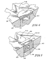
- FIGS. 1-5 An improved manifold for railroad vehicle brakes is illustrated in FIGS. 1-5 .
- the passages P do not extend in circuitous paths but continuously cross over each other without limitation. This allows greater flexibility and design of location of ports and elements on the manifold since the interconnection of the ports by the passages is not limited.
- the manifold 100 includes a front plate 110, having an exterior face 112 and an interior face 114 and a rear plate 120 having an exterior face 122 and an interior face 124.
- the interior faces 114 of plate 110 and 124 of plate 120 are bonded together.
- the front and rear plates 110 and 120 include bores B, passages P and chambers C, the center plate 130.
- Bore B 101 connects a port on exterior surface of plate 110 to passage P101.
- Passage P102 in rear plate 120 is connected to passage P101 by an overlap L101 and passage P103 in plate 110 by overlap L102.
- Passages P104 and P105 in rear plate 120 are connected to passage P103 by overlap L103.
- Passages P106, P107 and P108 in the front plate 110 cross over passages P102 and P104 in the rear plate 120 and are separated there from by crossover elements CR 106, CR107A and CR108A respectively.
- Passages P109, P110, P112 and P115 in the rear plate 120 cross over passages P101 and P103 in front plate 110 and are pneumatically isolated there from by crossover elements CR109, CR110, CR112A and CR115A respectively.
- Passages P105, P112 and P118 in the rear plate 120 cross over passages P117 in front plate 110 and are pneumatically isolated there from by crossover elements CR105A, CR112B and CR118 respectively.
- Passages P105, P110, P112 and P115 in the rear plate P120 cross over passage P119 in front plate 110 and are pneumatically isolated there from by crossover elements CR105B, CR110, CR112A and CR115B respectively.
- Passages P106, P111 and P120 in the front plate 110 cross over passage P112 in rear plate 120 and are pneumatically isolated there from by common crossover element CR112C.
- Passage P120 in the front plate 110 also crosses over passage P114 in rear plate 120 and is pneumatically isolated there from by crossover element CR114.
- Passages P107 and P108 in the front plate 110 cross over passage P121 in rear plate 120 and are pneumatically isolated there from by n crossover elements CR107B and CR108B respectively.
- Passage P122 in the front plate 110 crosses over passage P123 in rear plate 120 and is pneumatically isolated there from by crossover element CR122.
- Bore B101 in the front plate 110 is connected to passage P101.
- Bore B102 in plate 110 is coaxial with and connected to threaded bore B103 in plate 120.
- Chambers C101, C102 and C103 in the front plate 110 are coextensive and juxtapose chambers C104, C105 and C106 in the rear plate 120.
- a bore B105 in front plate 110 connects the chamber C101 to a port on exterior face 112 and connects chambers C101 and C104.
- a bore B110 connects a port on face 112 to chambers 102 and connects chambers C 102 and C105.
- bores B111 and B112 connect to ports on exterior surface 112 and chambers C103 and C106 together.
- Bores B113 and B 114 connect ports on exterior surface 112 to passage P117.
- Passage P119 is an example of a passage in the plate 110 lying between two passages P111 and P 116 in the plate 110.
- the crossing passage P115 in the plate 120 crosses over passage P119 and is connected to and connects passages P111 and P116.
- Through bores including B106, B107 and B108, B109 for example, are provided in the four corners in the two plates to receive fasteners for mounting the manifold 100 to an appropriate bracket.
- the passages P Comparing the passages P to the chamber C in FIGS. 2 and 3 , it will be noted that they are the same depth. Since the chambers are generally wider than the passages, they are not detrimentally affected by glue or the bonding agent extending into the chambers. By making the passages P the same depth as the chamber C, any bonding agent which accidentally gets in the passages P, would not restrict the passage.
- the front 110 is approximately 1.0 inches and the rear plates 120 is approximately 0.85 inches thick and the depth of the passages P and the chamber C are approximately 0.610 inches.
- crossover elements There are a) disks or plates which sit in a shallow recess 126 in the interior face 122 of the rear plate 120, b) a block with a bore which sits in a deeper recess 128 in the passage chamber and c) a portion of the interior face for the plate with a bore there below.
- the disks, CR118 are a circular disk which extends wider than the thickness of each of the intersecting passages to pneumatically isolate them from each other. By extending laterally, it provides support for the disk and provides for appropriate sealing of the elements.
- the disk in figure 3 is shown as a circular disk, it may be of oblong shape and may form a cross over element for two adjacent crossing passages.
- the depth of recess 126 maybe 0.23 inches.
- the original disk would have a thickness of 0.25 inches. After it is inserted and secured, the disks are machined until the top surface of the disk is planed down with the top surface 124 of the back plate 120.
- Block 140 has a bore 142 extending along its length which is the length of the crossing chamber or passage. Using the previous examples, the depth of the recess 128 would be 0.610 inches and the depth of the block 140 is 0.625 inches. As with the disk of figure 4 , the block is inserted and secured and then planed down such that its stop surface is planer with the interior surface 124 and the plate 120. Although the bottom of the recess for the blocks 140 is the bottom of the channel or passage, it may be raised from the bottom of the channel or passage.
- the disks have a chamfered circumference 140 at it is bottom edge to guide the disk into the recess 126.
- the block 140 includes bottom chamfered corners 146 at the bottom edge. The sides are machined for proper fit in the channel or passage.
- the diameter of the bore 142 may be for example 0.375.
- the chamfering surfaces 140 and 146 act as an alignment or lead for the crossover element in the recess during the press operation.
- the bores B, the passages P, the chambers C and the recesses for the crossover elements are machined in the front and rear plates 110 and 120.
- An example would be a vertical milling machine.
- FIG. 6A-D A method of the crossover element from a portion of the interior face for the plate with a bore there below is illustrated in Figures 6A-D .
- the example used is not present in Figure 1 .
- the interior surface 124 of plate 120 for example is machined with a vertical milling tool 230 to form passage segments P200A and P200B separated by portion 210 of the plate 120, as shown in Figure 6A .
- a bore 212 at an angle to the vertical is formed in the portion 210 from passage segment P200A using a milling tool 232, as shown in Figure 6B .
- the diameter of the milling tool 232 is less than or equal to the diameter of the milling tool 230.
- the milling tool 232 is moved horizontally in the passage segment P200A.
- the resulting structure of the bore 212 as illustrated in Figure 6C , is a tapered face 216 on the remaining portion of portion 210 and an indention 218 in the bottom of the passage P200.
- a bore 220 at an angle to the vertical is formed in the portion 210 from passage segment P200B using the milling tool 232, as shown in Figure 6C .
- the milling tool 232 is moved horizontally in the passage segment P200B.
- the resulting structure of the bore 220 is a tapered face 224 on the remaining portion of portion 210 and an indention 226 in the bottom of the passage P200.
- a small protuberance 228 is between indentions 218 and 226.
- the angle of the milling tool 232 may be in the range of 45 to 60 degrees from vertical. It will depend on depth of the passage P200 and the required length of the crossover element CR200.
- the resulting structure is a crossover element CR200 formed from the interior face 124 with a crossing passage segment P200C connecting the passage segments P200A and P 200B.
- the depth D1 of the crossing passage P200C from the interior face 124 to the top of protuberance 228 is greater than the depth D2 of the adjacent passage segments P200A and P 200B from the interior face 124.
- the method of assembly would include forming crossover element in and planar with the interior face 124 of the bottom plate 120.
- adhesive would be applied to the interior faces 114 and 124 of the front and rear plates 110 and 120 and they would be positioned and aligned on each other.
- the combined structure would then be clamped and the adhesive cured. If cured at room temperature, the curing would take 24 hours.
- the manifold 100 can be placed in 300° F. oven for four hours.
- a silk screening process is used to apply the adhesive.
- the order of applying the plates to each other is not critical.
Landscapes
- Engineering & Computer Science (AREA)
- Mechanical Engineering (AREA)
- Transportation (AREA)
- Physics & Mathematics (AREA)
- Fluid Mechanics (AREA)
- General Engineering & Computer Science (AREA)
- Valve Housings (AREA)
- Train Traffic Observation, Control, And Security (AREA)
- Road Paving Structures (AREA)
- Heat-Exchange Devices With Radiators And Conduit Assemblies (AREA)
Abstract
Description
- The present invention relates generally to pneumatic manifolds and more specifically to pneumatic manifolds for rail vehicle brakes.
- Manifolds for rail vehicle brakes include a plurality of faces having ports for connection to pneumatic devices, sources of pneumatic fluid and pneumatic circuits connected to the faces. In some cases, pneumatic devices are mounted on the face and in other cases, the pneumatic devices, sources of pneumatic fluid and pneumatic circuits are connected to the device by hoses or other couplings. The manifold is mounted to the rail vehicle. The rail vehicle may include locomotives or cars including freight, passenger and mass transit.
- One example of a prior art manifold, used for example in a freight locomotive known as CCB from New York Air Brake Corporation, is illustrated in
FIGS. 1-3 ofUS 5,803,124 . The manifold includes two plates having the interior faces machine to provide passages and chambers and the exterior faces machine to have bores for connecting the passages and chambers to ports on the exterior faces. The passages are generally shallower than the chambers. Adhesives are applied to the interior faces to bond the two plates together. The adhesives sometimes would extend into the shallow passages and block them. These manifolds had to be scrapped. Also, circuitous path had to be selected for the connection of the ports on either a common face or the opposite exterior faces. This limited the placement of the ports on the exterior faces of the manifold. This is particularly detrimental where the pneumatic devices are mounted on one of the faces instead of just mere connection to external or non-mounted pneumatic device. - For the prior art structure of
FIGS. 1-3 ofUS 5,803,124 , the two core plates, for example, are 3/4 of an inch thick. This allowed a chamber depth of 1/2 inch into each plate for a combined depth of one inch chambers. If a bypass was needed because of the layout, a 1/4 inch thick cover plate would be provided as a bypass plate on one of the exterior faces. - The prior art manifold to
FIGS. 1-3 was an improvement over a previous prior art manifold illustrated inFIG. 4 ofUS 5,803,124 . This included a center core plate with a pair of cover plates. The core plate was machined to include the chambers and passages and the cover plates provided connection to external ports. The cover plates were substantially thinner than the core plate. Typically, the core plate was one inch thick and the cover plate was 1/2 inch thick. The one-inch thick core plate limited the depths of the chambers to 3/4 of an inch. -
Figures 5-7 ofUS 5,803,124 illustrated a three plate manifold wherein the center plate formed the crossover separation between chambers and passages in the two outer plates. The center plate had a thickness in the range of 1/16 to ¼ of an inch and the cover plates were 3/4 of an inch thick. This manifold structure removes the limitation of the positioning of the chambers and passages. - The present invention provides the subject matter of claims 1 and 11. Preferred embodiments are described in the subclaims. The present manifold is a modification of the three plate manifold to two plates with all the same advantages. The present manifold includes first and second plates secured together at an inner face of each plate. A plurality of chambers and passages are in the inner faces of the plates and at least one port on an outer face of each plate connected to one of the chambers and passages. A crossover element in the inner face of the first plate separates a chamber or passage in the first plate from a chamber or passage in the second plate in the area where the chambers or passages cross.
- The crossover element has a face flush with the inner face of the first plate. The crossing chamber or passage in the first plate has a first width in the inner face of the first plate and the crossover element has a second width greater than the first width. The crossover element may be in a recess in the inner face of the first plate and the recess has a width greater than a width of the crossing chamber or passage in the first plate and a depth less that a depth of the crossing chamber or passage in the first plate.
- The crossover element may be a third plate, a disk and/or a block with a bore extending along the length of the crossing chamber or passage. Also, the crossover element may be a portion of the first plate over the crossing chamber or passage of the first plate. A portion of the crossing chamber or passage of the first plate below the crossover element has a depth into the first plate greater than the depth of an adjacent portion of the chamber or passage. The end walls of the crossover element are tapered.
- A first chamber or passage in the second plate lies between a second and third chamber or passage in the second plate. The crossing chamber or passage in the first plate extends over the first chamber or passage and is connected to the second and third chambers or passages.
- A method of making a manifold for a rail vehicle includes forming first and second plated each with a plurality of chambers and passages segments as a recess in an inner face of the plates and at least one port on an outer face of each plate connected to one of the chambers and passages. A crossover element is formed in the inner face of the first plate with a crossing chamber or passage there below connecting adjacent chamber or passage segments in the first plate. The inner surfaces of the first and second plates are positioned adjacent each other with the crossover element over a chamber or passage of the second plate and secured.
- The crossover element is formed to have a face flushed with the inner surface of the first plate. The crossover element may be formed by positioning it in the crossing chamber or passage with a face extending above the inner face of the first plate. Alternatively, the crossover element with a crossing chamber or passage there below may be formed by forming the crossing chamber or passage in the first plate below the inner surface of the first plate wherein the inner surface forms the crossover element.
- The method includes forming the chambers and passages segments as recesses in an inner face of the plates includes vertical milling. Forming the crossover element with a crossing chamber or passage there below includes milling at an angle to the vertical from each adjacent vertically milled chamber and passage segment. The milling at an angle includes moving the angled milling element horizontally in the adjacent chamber or passage segment so that the depth of the crossover passage from the inner surface is at least as deep as the depth of the adjacent chamber or passage segment.
- Other objects, advantages and novel features of the present invention will become apparent from the following detailed description when considered in conjunction with the accompanying drawings.
-
FIG. 1 is a transparent overlay of the passages, chambers and ports of a double core manifold of according to the principles of the present disclosure. -
FIG. 2 is an exploded cross-sectional view taken along lines II-II ofFIG. 1 . -
FIG. 3 is an exploded cross-sectional view taken along lines III-III ofFIG. 1 . -
FIG. 4 is a perspective cross-sectional view of a plate/disk crossover element according to the principles of the present disclosure. -
FIG. 5 is a perspective cross-sectional view of a block with a bore crossover element according to the principles of the present disclosure. -
FIG.s 6 A-D are cross-sectional views of a process for forming the crossover element according to the principles of the present disclosure - An improved manifold for railroad vehicle brakes is illustrated in
FIGS. 1-5 . In comparing some manifolds the prior art andFIG. 1 , it is evident that the passages P do not extend in circuitous paths but continuously cross over each other without limitation. This allows greater flexibility and design of location of ports and elements on the manifold since the interconnection of the ports by the passages is not limited. - Referring to
FIGS. 1-5 , themanifold 100 includes afront plate 110, having anexterior face 112 and aninterior face 114 and arear plate 120 having anexterior face 122 and aninterior face 124. The interior faces 114 ofplate plate 120 are bonded together. The front andrear plates - Bore B 101 connects a port on exterior surface of
plate 110 to passage P101. Passage P102 inrear plate 120 is connected to passage P101 by an overlap L101 and passage P103 inplate 110 by overlap L102. Passages P104 and P105 inrear plate 120 are connected to passage P103 by overlap L103. - Passages P106, P107 and P108 in the
front plate 110 cross over passages P102 and P104 in therear plate 120 and are separated there from by crossover elements CR 106, CR107A and CR108A respectively. Passages P109, P110, P112 and P115 in therear plate 120 cross over passages P101 and P103 infront plate 110 and are pneumatically isolated there from by crossover elements CR109, CR110, CR112A and CR115A respectively. Passages P105, P112 and P118 in therear plate 120 cross over passages P117 infront plate 110 and are pneumatically isolated there from by crossover elements CR105A, CR112B and CR118 respectively. Passages P105, P110, P112 and P115 in the rear plate P120 cross over passage P119 infront plate 110 and are pneumatically isolated there from by crossover elements CR105B, CR110, CR112A and CR115B respectively. - Passages P106, P111 and P120 in the
front plate 110 cross over passage P112 inrear plate 120 and are pneumatically isolated there from by common crossover element CR112C. Passage P120 in thefront plate 110 also crosses over passage P114 inrear plate 120 and is pneumatically isolated there from by crossover element CR114. Passages P107 and P108 in thefront plate 110 cross over passage P121 inrear plate 120 and are pneumatically isolated there from by n crossover elements CR107B and CR108B respectively. Passage P122 in thefront plate 110 crosses over passage P123 inrear plate 120 and is pneumatically isolated there from by crossover element CR122. - Bore B101 in the
front plate 110 is connected to passage P101. Bore B102 inplate 110 is coaxial with and connected to threaded bore B103 inplate 120. Chambers C101, C102 and C103 in thefront plate 110 are coextensive and juxtapose chambers C104, C105 and C106 in therear plate 120. A bore B105 infront plate 110 connects the chamber C101 to a port onexterior face 112 and connects chambers C101 and C104. A bore B110 connects a port onface 112 to chambers 102 and connects chambers C 102 and C105. Similarly, bores B111 and B112 connect to ports onexterior surface 112 and chambers C103 and C106 together. Bores B113 andB 114 connect ports onexterior surface 112 to passage P117. - Passage P119 is an example of a passage in the
plate 110 lying between two passages P111 and P 116 in theplate 110. The crossing passage P115 in theplate 120 crosses over passage P119 and is connected to and connects passages P111 and P116. - Through bores, including B106, B107 and B108, B109 for example, are provided in the four corners in the two plates to receive fasteners for mounting the manifold 100 to an appropriate bracket.
- Comparing the passages P to the chamber C in
FIGS. 2 and3 , it will be noted that they are the same depth. Since the chambers are generally wider than the passages, they are not detrimentally affected by glue or the bonding agent extending into the chambers. By making the passages P the same depth as the chamber C, any bonding agent which accidentally gets in the passages P, would not restrict the passage. As a typical example, the front 110 is approximately 1.0 inches and therear plates 120 is approximately 0.85 inches thick and the depth of the passages P and the chamber C are approximately 0.610 inches. - The following are three basic types of crossover elements that may be used in the present manifold design. There are a) disks or plates which sit in a
shallow recess 126 in theinterior face 122 of therear plate 120, b) a block with a bore which sits in adeeper recess 128 in the passage chamber and c) a portion of the interior face for the plate with a bore there below. - As shown in
Figures 1 and4 , the disks, CR118 are a circular disk which extends wider than the thickness of each of the intersecting passages to pneumatically isolate them from each other. By extending laterally, it provides support for the disk and provides for appropriate sealing of the elements. Although the disk infigure 3 is shown as a circular disk, it may be of oblong shape and may form a cross over element for two adjacent crossing passages. - For the
plate 120 having a thickness of 0.85 inches and a channel depth of 0.610 inches for example, the depth ofrecess 126 maybe 0.23 inches. The original disk would have a thickness of 0.25 inches. After it is inserted and secured, the disks are machined until the top surface of the disk is planed down with thetop surface 124 of theback plate 120. - The block with the bore in a passage is illustrated in
Figure 5 .Block 140 has abore 142 extending along its length which is the length of the crossing chamber or passage. Using the previous examples, the depth of therecess 128 would be 0.610 inches and the depth of theblock 140 is 0.625 inches. As with the disk offigure 4 , the block is inserted and secured and then planed down such that its stop surface is planer with theinterior surface 124 and theplate 120. Although the bottom of the recess for theblocks 140 is the bottom of the channel or passage, it may be raised from the bottom of the channel or passage. - The disks have a chamfered
circumference 140 at it is bottom edge to guide the disk into therecess 126. Theblock 140 includes bottom chamferedcorners 146 at the bottom edge. The sides are machined for proper fit in the channel or passage. The diameter of thebore 142 may be for example 0.375. The chamfering surfaces 140 and 146 act as an alignment or lead for the crossover element in the recess during the press operation. - The bores B, the passages P, the chambers C and the recesses for the crossover elements are machined in the front and
rear plates - A method of the crossover element from a portion of the interior face for the plate with a bore there below is illustrated in
Figures 6A-D . The example used is not present inFigure 1 . Theinterior surface 124 ofplate 120 for example is machined with avertical milling tool 230 to form passage segments P200A and P200B separated byportion 210 of theplate 120, as shown inFigure 6A . - Next a bore 212 at an angle to the vertical is formed in the
portion 210 from passage segment P200A using amilling tool 232, as shown inFigure 6B . The diameter of themilling tool 232 is less than or equal to the diameter of themilling tool 230. In order to remove the resultingobstruction portion 214 ofportion 210, themilling tool 232 is moved horizontally in the passage segment P200A. The resulting structure of the bore 212, as illustrated inFigure 6C , is atapered face 216 on the remaining portion ofportion 210 and anindention 218 in the bottom of the passage P200. - Next a
bore 220 at an angle to the vertical is formed in theportion 210 from passage segment P200B using themilling tool 232, as shown inFigure 6C . In order to remove the resulting obstruction portion 22 ofportion 210, themilling tool 232 is moved horizontally in the passage segment P200B. The resulting structure of thebore 220, as illustrated inFigure 6D , is atapered face 224 on the remaining portion ofportion 210 and anindention 226 in the bottom of the passage P200. Asmall protuberance 228 is betweenindentions - The angle of the
milling tool 232 may be in the range of 45 to 60 degrees from vertical. It will depend on depth of the passage P200 and the required length of the crossover element CR200. - The resulting structure is a crossover element CR200 formed from the
interior face 124 with a crossing passage segment P200C connecting the passage segments P200A and P 200B. The depth D1 of the crossing passage P200C from theinterior face 124 to the top ofprotuberance 228 is greater than the depth D2 of the adjacent passage segments P200A and P 200B from theinterior face 124. - The method of assembly would include forming crossover element in and planar with the
interior face 124 of thebottom plate 120. Next adhesive would be applied to the interior faces 114 and 124 of the front andrear plates - Although the present invention has been described and illustrated in detail, it is to be clearly understood that the same is by way of illustration and example only, and is not to be taken by way of limitation. Although a locomotive brake manifold has been used by way of example, the present invention is applicable to any manifold requiring a substantial number of connections and interconnections of ports on different faces of the manifold. The scope of the present invention is to be limited only by the terms of the appended claims.
Claims (20)
- A manifold for a rail vehicle comprising:first and second plates secured together at an inner face of each plate;a plurality of chambers and passages in the inner faces of the plates and at least one port on an outer face of each plate connected to one of the chambers and passages; anda crossover element separating a chamber or passage in the first plate from a chamber or passage in the second plate in the area where the chambers or passages cross;wherein the crossover element is in the inner face of the first plate at the crossing chamber or passage.
- The manifold of Claim 1, wherein the crossover element has a face flush with the inner face of the first plate.
- The manifold of Claim 1, wherein the crossing chamber or passage in the first plate has a first width in the inner face of the first plate and the crossover element has a second width greater than the first width.
- The manifold of Claim 1, wherein the crossover element is in a recess in the inner face of the first plate and the recess has a width greater than a width of the crossing chamber or passage in the first plate and a depth less that a depth of the crossing chamber or passage in the first plate.
- The manifold of Claim 1, wherein the crossover element is a disk or third plate in the first plate.
- The manifold of Claim 1, wherein the crossover element is a block with a bore extending along the length of the crossing chamber or passage.
- The manifold of Claim 1, wherein the crossover element is a portion of the first plate over the crossing chamber or passage of the first plate.
- The manifold of Claim 7, wherein a portion of the crossing chamber or passage of the first plate below the crossover element has a depth into the first plate greater than the depth of an adjacent portion of the chamber or passage.
- The manifold of Claim 7, wherein end walls of the crossover element are tapered.
- The manifold of Claim 1, wherein a first chamber or passage in the second plate lies between a second and third chamber or passage in the second plate and the crossing chamber or passage in the first plate extends over the first chamber or passage and is connected to the second and third chambers or passages.
- A method of making a manifold for a rail vehicle comprising:forming first and second plates each with a plurality of chambers and passages segments as recesses in an inner face of the plates and at least one port on an outer face of each plate connected to one of the chambers and passages;forming a crossover element in the inner face of the first plate with a crossing chamber or passage there below connecting adjacent chamber or passage segments in the first plate;positioning the inner surfaces of the first and second plates adjacent each other with the crossover element over a chamber or passage of the second plate; andsecuring the first and second plates to each other at the inner surfaces.
- The method of Claim 11, wherein the crossover element is formed to have a face flush with the inner face of the first plate before the securing.
- The method of Claim 11, wherein the crossover element is positioned in the crossing chamber or passage with a face extending above the inner face of the first plate; and including reducing the height of the face of the crossing element to be flush with the inner face of the first plate before the securing.
- The method of Claim 11 wherein the crossing chamber or passage in the first plate is formed to have a first width in the inner face of the first plate and the crossover element has a second width greater than the first width.
- The method of Claim 11, wherein the crossover element is in a recess formed in the inner face of the first plate and the recess is formed to have a width greater than a width of the crossing chamber or passage in the first plate and a depth less that a depth of the crossing chamber or passage in the first plate.
- The method of Claim 11, wherein the crossover element is one of a third plate, a disk and a block with a bore extending along the length of the crossing chamber or passage.
- The method of Claim 11, wherein a first chamber or passage formed in the second plate lies between a second and third chamber or passage formed in the second plate and the crossing chamber or passage in the first plate is formed to extends over the first chamber or passage and is connected to the second and third chambers or passages when the first and second plated are secure to each other.
- The method of Claim 11, wherein forming the crossover element with a crossing chamber or passage there below includes forming the crossing chamber or passage in the first plate below the inner surface of the first plate wherein the inner surface forms the crossover element.
- The method of Claim 11, wherein:forming the chambers and passages segments as recesses in an inner face of the plates includes vertical milling; andforming the crossover element with a crossing chamber or passage there below includes milling at an angle to the vertical from each adjacent vertically milled chamber and passage segment.
- The method of Claim 19, wherein milling at an angle includes moving the angled milling element horizontally in the adjacent chamber or passage segment so that the depth of the crossover passage from the inner surface is at least as deep as the depth of the adjacent chamber or passage segment.
Applications Claiming Priority (2)
| Application Number | Priority Date | Filing Date | Title |
|---|---|---|---|
| US12/250,011 US8439079B2 (en) | 2008-10-13 | 2008-10-13 | Two plate manifold with crossovers |
| US12/565,384 US8528587B2 (en) | 2008-10-13 | 2009-09-23 | Two plate manifold with crossovers |
Publications (3)
| Publication Number | Publication Date |
|---|---|
| EP2174848A2 true EP2174848A2 (en) | 2010-04-14 |
| EP2174848A3 EP2174848A3 (en) | 2012-12-05 |
| EP2174848B1 EP2174848B1 (en) | 2016-04-27 |
Family
ID=41478860
Family Applications (1)
| Application Number | Title | Priority Date | Filing Date |
|---|---|---|---|
| EP09172312.2A Not-in-force EP2174848B1 (en) | 2008-10-13 | 2009-10-06 | Two plate manifold with crossovers |
Country Status (5)
| Country | Link |
|---|---|
| US (1) | US8528587B2 (en) |
| EP (1) | EP2174848B1 (en) |
| CN (1) | CN101722948B (en) |
| AU (1) | AU2009225288B2 (en) |
| CA (1) | CA2681680C (en) |
Cited By (1)
| Publication number | Priority date | Publication date | Assignee | Title |
|---|---|---|---|---|
| WO2026057742A1 (en) * | 2024-09-14 | 2026-03-19 | Valeo Systemes Thermiques | Manifold plate assembly and thermal management system |
Families Citing this family (1)
| Publication number | Priority date | Publication date | Assignee | Title |
|---|---|---|---|---|
| EP3423908A4 (en) * | 2016-02-24 | 2019-12-11 | Leanna Levine | MECHANICAL DRIVE SEQUENCING COLLECTOR |
Citations (1)
| Publication number | Priority date | Publication date | Assignee | Title |
|---|---|---|---|---|
| US5803124A (en) | 1996-12-27 | 1998-09-08 | New York Air Brake Corporation | Rail vehicle brake manifold |
Family Cites Families (8)
| Publication number | Priority date | Publication date | Assignee | Title |
|---|---|---|---|---|
| DE2033736C3 (en) * | 1970-07-08 | 1978-03-30 | Klaus 7300 Esslingen Huegler | Universal control block for liquid or gaseous media |
| US4449426A (en) | 1977-08-15 | 1984-05-22 | Younger Gilbert W | Laminated separator plate means for recalibrating automatic transmissions |
| US4951709A (en) | 1988-11-01 | 1990-08-28 | Komatsu Dresser Company | Hydraulic system and manifold assembly |
| US5439026A (en) * | 1992-12-11 | 1995-08-08 | Tokyo Electron Limited | Processing apparatus and flow control arrangement therefor |
| IL115327A (en) * | 1994-10-07 | 2000-08-13 | Bayer Ag | Diaphragm pump |
| US5720317A (en) * | 1996-08-21 | 1998-02-24 | Pgi International, Ltd. | Low profile flanged manifold valve |
| US6000427A (en) * | 1998-10-19 | 1999-12-14 | Hutton; Peter B. | Manifold for use with dual pressure sensor units |
| US7004199B1 (en) * | 2004-08-04 | 2006-02-28 | Fujikin Incorporated | Fluid control apparatus |
-
2009
- 2009-09-23 US US12/565,384 patent/US8528587B2/en not_active Expired - Fee Related
- 2009-10-06 CA CA 2681680 patent/CA2681680C/en not_active Expired - Fee Related
- 2009-10-06 EP EP09172312.2A patent/EP2174848B1/en not_active Not-in-force
- 2009-10-12 AU AU2009225288A patent/AU2009225288B2/en not_active Ceased
- 2009-10-13 CN CN200910180412.7A patent/CN101722948B/en not_active Expired - Fee Related
Patent Citations (1)
| Publication number | Priority date | Publication date | Assignee | Title |
|---|---|---|---|---|
| US5803124A (en) | 1996-12-27 | 1998-09-08 | New York Air Brake Corporation | Rail vehicle brake manifold |
Cited By (1)
| Publication number | Priority date | Publication date | Assignee | Title |
|---|---|---|---|---|
| WO2026057742A1 (en) * | 2024-09-14 | 2026-03-19 | Valeo Systemes Thermiques | Manifold plate assembly and thermal management system |
Also Published As
| Publication number | Publication date |
|---|---|
| AU2009225288A1 (en) | 2010-04-29 |
| CA2681680C (en) | 2014-12-09 |
| US20100089476A1 (en) | 2010-04-15 |
| CN101722948A (en) | 2010-06-09 |
| AU2009225288B2 (en) | 2014-07-10 |
| US8528587B2 (en) | 2013-09-10 |
| EP2174848A3 (en) | 2012-12-05 |
| CN101722948B (en) | 2014-06-11 |
| EP2174848B1 (en) | 2016-04-27 |
| CA2681680A1 (en) | 2010-04-13 |
Similar Documents
| Publication | Publication Date | Title |
|---|---|---|
| CN107791049B (en) | Method for clamping and machining hydraulic block of sliding-adjusted hydraulic vehicle brake device and hydraulic block | |
| EP2066939B1 (en) | Valve control unit, particularly pilot control unit for a pressure modulator of a commercial vehicle | |
| JP5474058B2 (en) | Pressure control valve device comprising a diaphragm valve comprising a diaphragm arranged in a parallel plane or in the same plane for controlling fluid pressure in an ABS brake device of a vehicle | |
| US5803124A (en) | Rail vehicle brake manifold | |
| EP2174848B1 (en) | Two plate manifold with crossovers | |
| ZA200907074B (en) | Two plate manifold with crossovers | |
| US20180180070A1 (en) | Valve body for hydraulic control device, and production method therefor | |
| CN105555566A (en) | Air filter for a ventilation device of a motor vehicle and method for mounting same | |
| EP3914491B1 (en) | Railway braking device and manufacturing method of a railway braking device | |
| JP6536745B2 (en) | Hydraulic control device for automatic transmission and method of manufacturing the same | |
| JP4982192B2 (en) | Degassing member for injection mold | |
| JP2006264163A (en) | Vacuum forming mold and its manufacturing method | |
| JP4310540B2 (en) | Synthetic resin porous flow path plate and manufacturing method thereof | |
| KR20240164447A (en) | Constructing parts using cut layer additive manufacturing | |
| JP5911073B2 (en) | Manifold and method of forming manifold | |
| JP2019142078A (en) | Manufacturing method of molded structure | |
| US10851902B2 (en) | Cross-flow dual valve and method of manufacturing housing of the cross-flow dual valve | |
| KR20130143513A (en) | Injection-molded parts for compensating for part warpage | |
| US20140110620A1 (en) | Split and brazed powdered metal valve body | |
| CN1112293C (en) | Actuator support assembly | |
| CN1868733A (en) | Fluid coupler and a device arranged with the same | |
| DE102013001207A1 (en) | Method for manufacturing fiber composite component, involves forming predetermined shape of silicone diaphragm and fixing formed shape of diaphragm by evacuating sealed space, before placing semi-finished material between diaphragms |
Legal Events
| Date | Code | Title | Description |
|---|---|---|---|
| PUAI | Public reference made under article 153(3) epc to a published international application that has entered the european phase |
Free format text: ORIGINAL CODE: 0009012 |
|
| AK | Designated contracting states |
Kind code of ref document: A2 Designated state(s): AT BE BG CH CY CZ DE DK EE ES FI FR GB GR HR HU IE IS IT LI LT LU LV MC MK MT NL NO PL PT RO SE SI SK SM TR |
|
| AX | Request for extension of the european patent |
Extension state: AL BA RS |
|
| PUAL | Search report despatched |
Free format text: ORIGINAL CODE: 0009013 |
|
| AK | Designated contracting states |
Kind code of ref document: A3 Designated state(s): AT BE BG CH CY CZ DE DK EE ES FI FR GB GR HR HU IE IS IT LI LT LU LV MC MK MT NL NO PL PT RO SE SI SK SM TR |
|
| AX | Request for extension of the european patent |
Extension state: AL BA RS |
|
| RIC1 | Information provided on ipc code assigned before grant |
Ipc: B60T 17/22 20060101ALI20121026BHEP Ipc: B60T 13/66 20060101ALI20121026BHEP Ipc: F15B 13/08 20060101ALI20121026BHEP Ipc: B60T 17/04 20060101AFI20121026BHEP |
|
| 17P | Request for examination filed |
Effective date: 20130603 |
|
| RBV | Designated contracting states (corrected) |
Designated state(s): AT BE BG CH CY CZ DE DK EE ES FI FR GB GR HR HU IE IS IT LI LT LU LV MC MK MT NL NO PL PT RO SE SI SK SM TR |
|
| GRAP | Despatch of communication of intention to grant a patent |
Free format text: ORIGINAL CODE: EPIDOSNIGR1 |
|
| INTG | Intention to grant announced |
Effective date: 20150924 |
|
| GRAS | Grant fee paid |
Free format text: ORIGINAL CODE: EPIDOSNIGR3 |
|
| INTG | Intention to grant announced |
Effective date: 20160226 |
|
| GRAA | (expected) grant |
Free format text: ORIGINAL CODE: 0009210 |
|
| AK | Designated contracting states |
Kind code of ref document: B1 Designated state(s): AT BE BG CH CY CZ DE DK EE ES FI FR GB GR HR HU IE IS IT LI LT LU LV MC MK MT NL NO PL PT RO SE SI SK SM TR |
|
| REG | Reference to a national code |
Ref country code: GB Ref legal event code: FG4D |
|
| REG | Reference to a national code |
Ref country code: CH Ref legal event code: EP |
|
| REG | Reference to a national code |
Ref country code: AT Ref legal event code: REF Ref document number: 794400 Country of ref document: AT Kind code of ref document: T Effective date: 20160515 |
|
| REG | Reference to a national code |
Ref country code: IE Ref legal event code: FG4D |
|
| REG | Reference to a national code |
Ref country code: DE Ref legal event code: R096 Ref document number: 602009038171 Country of ref document: DE |
|
| REG | Reference to a national code |
Ref country code: LT Ref legal event code: MG4D |
|
| REG | Reference to a national code |
Ref country code: NL Ref legal event code: MP Effective date: 20160427 |
|
| REG | Reference to a national code |
Ref country code: AT Ref legal event code: MK05 Ref document number: 794400 Country of ref document: AT Kind code of ref document: T Effective date: 20160427 |
|
| PG25 | Lapsed in a contracting state [announced via postgrant information from national office to epo] |
Ref country code: NL Free format text: LAPSE BECAUSE OF FAILURE TO SUBMIT A TRANSLATION OF THE DESCRIPTION OR TO PAY THE FEE WITHIN THE PRESCRIBED TIME-LIMIT Effective date: 20160427 |
|
| REG | Reference to a national code |
Ref country code: FR Ref legal event code: PLFP Year of fee payment: 8 |
|
| PG25 | Lapsed in a contracting state [announced via postgrant information from national office to epo] |
Ref country code: FI Free format text: LAPSE BECAUSE OF FAILURE TO SUBMIT A TRANSLATION OF THE DESCRIPTION OR TO PAY THE FEE WITHIN THE PRESCRIBED TIME-LIMIT Effective date: 20160427 Ref country code: LT Free format text: LAPSE BECAUSE OF FAILURE TO SUBMIT A TRANSLATION OF THE DESCRIPTION OR TO PAY THE FEE WITHIN THE PRESCRIBED TIME-LIMIT Effective date: 20160427 Ref country code: NO Free format text: LAPSE BECAUSE OF FAILURE TO SUBMIT A TRANSLATION OF THE DESCRIPTION OR TO PAY THE FEE WITHIN THE PRESCRIBED TIME-LIMIT Effective date: 20160727 Ref country code: PL Free format text: LAPSE BECAUSE OF FAILURE TO SUBMIT A TRANSLATION OF THE DESCRIPTION OR TO PAY THE FEE WITHIN THE PRESCRIBED TIME-LIMIT Effective date: 20160427 |
|
| PG25 | Lapsed in a contracting state [announced via postgrant information from national office to epo] |
Ref country code: HR Free format text: LAPSE BECAUSE OF FAILURE TO SUBMIT A TRANSLATION OF THE DESCRIPTION OR TO PAY THE FEE WITHIN THE PRESCRIBED TIME-LIMIT Effective date: 20160427 Ref country code: GR Free format text: LAPSE BECAUSE OF FAILURE TO SUBMIT A TRANSLATION OF THE DESCRIPTION OR TO PAY THE FEE WITHIN THE PRESCRIBED TIME-LIMIT Effective date: 20160728 Ref country code: PT Free format text: LAPSE BECAUSE OF FAILURE TO SUBMIT A TRANSLATION OF THE DESCRIPTION OR TO PAY THE FEE WITHIN THE PRESCRIBED TIME-LIMIT Effective date: 20160829 Ref country code: SE Free format text: LAPSE BECAUSE OF FAILURE TO SUBMIT A TRANSLATION OF THE DESCRIPTION OR TO PAY THE FEE WITHIN THE PRESCRIBED TIME-LIMIT Effective date: 20160427 Ref country code: AT Free format text: LAPSE BECAUSE OF FAILURE TO SUBMIT A TRANSLATION OF THE DESCRIPTION OR TO PAY THE FEE WITHIN THE PRESCRIBED TIME-LIMIT Effective date: 20160427 Ref country code: ES Free format text: LAPSE BECAUSE OF FAILURE TO SUBMIT A TRANSLATION OF THE DESCRIPTION OR TO PAY THE FEE WITHIN THE PRESCRIBED TIME-LIMIT Effective date: 20160427 Ref country code: LV Free format text: LAPSE BECAUSE OF FAILURE TO SUBMIT A TRANSLATION OF THE DESCRIPTION OR TO PAY THE FEE WITHIN THE PRESCRIBED TIME-LIMIT Effective date: 20160427 |
|
| PG25 | Lapsed in a contracting state [announced via postgrant information from national office to epo] |
Ref country code: IT Free format text: LAPSE BECAUSE OF FAILURE TO SUBMIT A TRANSLATION OF THE DESCRIPTION OR TO PAY THE FEE WITHIN THE PRESCRIBED TIME-LIMIT Effective date: 20160427 Ref country code: BE Free format text: LAPSE BECAUSE OF FAILURE TO SUBMIT A TRANSLATION OF THE DESCRIPTION OR TO PAY THE FEE WITHIN THE PRESCRIBED TIME-LIMIT Effective date: 20160427 |
|
| REG | Reference to a national code |
Ref country code: DE Ref legal event code: R097 Ref document number: 602009038171 Country of ref document: DE |
|
| PG25 | Lapsed in a contracting state [announced via postgrant information from national office to epo] |
Ref country code: CZ Free format text: LAPSE BECAUSE OF FAILURE TO SUBMIT A TRANSLATION OF THE DESCRIPTION OR TO PAY THE FEE WITHIN THE PRESCRIBED TIME-LIMIT Effective date: 20160427 Ref country code: EE Free format text: LAPSE BECAUSE OF FAILURE TO SUBMIT A TRANSLATION OF THE DESCRIPTION OR TO PAY THE FEE WITHIN THE PRESCRIBED TIME-LIMIT Effective date: 20160427 Ref country code: SK Free format text: LAPSE BECAUSE OF FAILURE TO SUBMIT A TRANSLATION OF THE DESCRIPTION OR TO PAY THE FEE WITHIN THE PRESCRIBED TIME-LIMIT Effective date: 20160427 Ref country code: DK Free format text: LAPSE BECAUSE OF FAILURE TO SUBMIT A TRANSLATION OF THE DESCRIPTION OR TO PAY THE FEE WITHIN THE PRESCRIBED TIME-LIMIT Effective date: 20160427 Ref country code: RO Free format text: LAPSE BECAUSE OF FAILURE TO SUBMIT A TRANSLATION OF THE DESCRIPTION OR TO PAY THE FEE WITHIN THE PRESCRIBED TIME-LIMIT Effective date: 20160427 |
|
| PG25 | Lapsed in a contracting state [announced via postgrant information from national office to epo] |
Ref country code: SM Free format text: LAPSE BECAUSE OF FAILURE TO SUBMIT A TRANSLATION OF THE DESCRIPTION OR TO PAY THE FEE WITHIN THE PRESCRIBED TIME-LIMIT Effective date: 20160427 |
|
| PLBE | No opposition filed within time limit |
Free format text: ORIGINAL CODE: 0009261 |
|
| STAA | Information on the status of an ep patent application or granted ep patent |
Free format text: STATUS: NO OPPOSITION FILED WITHIN TIME LIMIT |
|
| 26N | No opposition filed |
Effective date: 20170130 |
|
| PG25 | Lapsed in a contracting state [announced via postgrant information from national office to epo] |
Ref country code: SI Free format text: LAPSE BECAUSE OF FAILURE TO SUBMIT A TRANSLATION OF THE DESCRIPTION OR TO PAY THE FEE WITHIN THE PRESCRIBED TIME-LIMIT Effective date: 20160427 |
|
| REG | Reference to a national code |
Ref country code: CH Ref legal event code: PL |
|
| REG | Reference to a national code |
Ref country code: IE Ref legal event code: MM4A |
|
| PG25 | Lapsed in a contracting state [announced via postgrant information from national office to epo] |
Ref country code: CH Free format text: LAPSE BECAUSE OF NON-PAYMENT OF DUE FEES Effective date: 20161031 Ref country code: LI Free format text: LAPSE BECAUSE OF NON-PAYMENT OF DUE FEES Effective date: 20161031 |
|
| PG25 | Lapsed in a contracting state [announced via postgrant information from national office to epo] |
Ref country code: LU Free format text: LAPSE BECAUSE OF NON-PAYMENT OF DUE FEES Effective date: 20161006 |
|
| REG | Reference to a national code |
Ref country code: FR Ref legal event code: PLFP Year of fee payment: 9 |
|
| PG25 | Lapsed in a contracting state [announced via postgrant information from national office to epo] |
Ref country code: IE Free format text: LAPSE BECAUSE OF NON-PAYMENT OF DUE FEES Effective date: 20161006 |
|
| PG25 | Lapsed in a contracting state [announced via postgrant information from national office to epo] |
Ref country code: CY Free format text: LAPSE BECAUSE OF FAILURE TO SUBMIT A TRANSLATION OF THE DESCRIPTION OR TO PAY THE FEE WITHIN THE PRESCRIBED TIME-LIMIT Effective date: 20160427 Ref country code: HU Free format text: LAPSE BECAUSE OF FAILURE TO SUBMIT A TRANSLATION OF THE DESCRIPTION OR TO PAY THE FEE WITHIN THE PRESCRIBED TIME-LIMIT; INVALID AB INITIO Effective date: 20091006 |
|
| PG25 | Lapsed in a contracting state [announced via postgrant information from national office to epo] |
Ref country code: TR Free format text: LAPSE BECAUSE OF FAILURE TO SUBMIT A TRANSLATION OF THE DESCRIPTION OR TO PAY THE FEE WITHIN THE PRESCRIBED TIME-LIMIT Effective date: 20160427 Ref country code: MC Free format text: LAPSE BECAUSE OF FAILURE TO SUBMIT A TRANSLATION OF THE DESCRIPTION OR TO PAY THE FEE WITHIN THE PRESCRIBED TIME-LIMIT Effective date: 20160427 Ref country code: MK Free format text: LAPSE BECAUSE OF FAILURE TO SUBMIT A TRANSLATION OF THE DESCRIPTION OR TO PAY THE FEE WITHIN THE PRESCRIBED TIME-LIMIT Effective date: 20160427 Ref country code: IS Free format text: LAPSE BECAUSE OF FAILURE TO SUBMIT A TRANSLATION OF THE DESCRIPTION OR TO PAY THE FEE WITHIN THE PRESCRIBED TIME-LIMIT Effective date: 20160427 Ref country code: MT Free format text: LAPSE BECAUSE OF NON-PAYMENT OF DUE FEES Effective date: 20161031 |
|
| PG25 | Lapsed in a contracting state [announced via postgrant information from national office to epo] |
Ref country code: BG Free format text: LAPSE BECAUSE OF FAILURE TO SUBMIT A TRANSLATION OF THE DESCRIPTION OR TO PAY THE FEE WITHIN THE PRESCRIBED TIME-LIMIT Effective date: 20160427 |
|
| REG | Reference to a national code |
Ref country code: FR Ref legal event code: PLFP Year of fee payment: 10 |
|
| PGFP | Annual fee paid to national office [announced via postgrant information from national office to epo] |
Ref country code: DE Payment date: 20191029 Year of fee payment: 11 |
|
| PGFP | Annual fee paid to national office [announced via postgrant information from national office to epo] |
Ref country code: FR Payment date: 20191025 Year of fee payment: 11 |
|
| PGFP | Annual fee paid to national office [announced via postgrant information from national office to epo] |
Ref country code: GB Payment date: 20191028 Year of fee payment: 11 |
|
| REG | Reference to a national code |
Ref country code: DE Ref legal event code: R119 Ref document number: 602009038171 Country of ref document: DE |
|
| GBPC | Gb: european patent ceased through non-payment of renewal fee |
Effective date: 20201006 |
|
| PG25 | Lapsed in a contracting state [announced via postgrant information from national office to epo] |
Ref country code: FR Free format text: LAPSE BECAUSE OF NON-PAYMENT OF DUE FEES Effective date: 20201031 Ref country code: DE Free format text: LAPSE BECAUSE OF NON-PAYMENT OF DUE FEES Effective date: 20210501 |
|
| PG25 | Lapsed in a contracting state [announced via postgrant information from national office to epo] |
Ref country code: GB Free format text: LAPSE BECAUSE OF NON-PAYMENT OF DUE FEES Effective date: 20201006 |