EP2174844A1 - Method and device for placing an airbag in a protective sheath - Google Patents
Method and device for placing an airbag in a protective sheath Download PDFInfo
- Publication number
- EP2174844A1 EP2174844A1 EP08017635A EP08017635A EP2174844A1 EP 2174844 A1 EP2174844 A1 EP 2174844A1 EP 08017635 A EP08017635 A EP 08017635A EP 08017635 A EP08017635 A EP 08017635A EP 2174844 A1 EP2174844 A1 EP 2174844A1
- Authority
- EP
- European Patent Office
- Prior art keywords
- airbag
- protective sheet
- protective
- folded
- protective sheath
- Prior art date
- Legal status (The legal status is an assumption and is not a legal conclusion. Google has not performed a legal analysis and makes no representation as to the accuracy of the status listed.)
- Withdrawn
Links
Images


Classifications
-
- B—PERFORMING OPERATIONS; TRANSPORTING
- B60—VEHICLES IN GENERAL
- B60R—VEHICLES, VEHICLE FITTINGS, OR VEHICLE PARTS, NOT OTHERWISE PROVIDED FOR
- B60R21/00—Arrangements or fittings on vehicles for protecting or preventing injuries to occupants or pedestrians in case of accidents or other traffic risks
- B60R21/02—Occupant safety arrangements or fittings, e.g. crash pads
- B60R21/16—Inflatable occupant restraints or confinements designed to inflate upon impact or impending impact, e.g. air bags
- B60R21/23—Inflatable members
- B60R21/237—Inflatable members characterised by the way they are folded
-
- B—PERFORMING OPERATIONS; TRANSPORTING
- B60—VEHICLES IN GENERAL
- B60R—VEHICLES, VEHICLE FITTINGS, OR VEHICLE PARTS, NOT OTHERWISE PROVIDED FOR
- B60R21/00—Arrangements or fittings on vehicles for protecting or preventing injuries to occupants or pedestrians in case of accidents or other traffic risks
- B60R21/02—Occupant safety arrangements or fittings, e.g. crash pads
- B60R21/16—Inflatable occupant restraints or confinements designed to inflate upon impact or impending impact, e.g. air bags
- B60R21/20—Arrangements for storing inflatable members in their non-use or deflated condition; Arrangement or mounting of air bag modules or components
- B60R21/201—Packaging straps or envelopes for inflatable members
-
- B—PERFORMING OPERATIONS; TRANSPORTING
- B60—VEHICLES IN GENERAL
- B60R—VEHICLES, VEHICLE FITTINGS, OR VEHICLE PARTS, NOT OTHERWISE PROVIDED FOR
- B60R21/00—Arrangements or fittings on vehicles for protecting or preventing injuries to occupants or pedestrians in case of accidents or other traffic risks
- B60R21/02—Occupant safety arrangements or fittings, e.g. crash pads
- B60R21/16—Inflatable occupant restraints or confinements designed to inflate upon impact or impending impact, e.g. air bags
- B60R21/23—Inflatable members
- B60R21/237—Inflatable members characterised by the way they are folded
- B60R2021/2375—Folding devices
Definitions
- the invention relates to a method of placing an airbag in a protective sheath as well as to a device for carrying out this method.
- DE 102 55 119 B3 discloses a method of placing such an airbag in an elongated encasement, with the pre-folded airbag firstly being inserted in a profile rail having a U-shaped cross-section; after this, the profile rail together with the airbag is inserted in a prefabricated, elongate tube encasement. This tube encasement finally is withdrawn from the profile rail together with the pre-folded airbag, so that the airbag is placed in the encasement as desired.
- the encasing material at first is available as a one-ply band, it has to be prefabricated at first to a tube-like envelope. This separate work step as well as the subsequent introducing and withdrawing of the profile rail or the encasement in the longitudinal direction of the tube-like envelope make the described method labor-intensive and costly.
- the protective sheet As the protective sheet is laid around the pre-folded airbag almost simultaneously in one work step and is connected so as to form a protective sheath, preferably by sewing, the prefabrication of the protective sheath as well as the expensive insertion and extraction of the profile rail or protective sheath can be omitted. Accordingly, the method of placing the airbag in the protective sheath becomes more efficient on the whole and thus more cost-effective.
- the opposing free edges of the protective sheet are connected with each other, while the pre-folded airbag is separated from the protective sheet by a profile structural component. It is ensured thereby that the protective sheet is not inadvertently connected with portions of the pre-folded airbag and that the deployment of the airbag upon activation of the airbag module is not hindered.
- the airbag has a longitudinal axis, and a connection device is preferably provided for connecting the opposing free edges of the protective sheet, the airbag together with the protective sheet being moved relative to the connection device in axial direction during the combined working operation of the steps c) and d).
- the airbag thus is placed in the protective sheath by a one-time, linear movement in axial direction, which sheath is fabricated from the protective sheet not before, but during this movement.
- a prefabrication of the protective sheath can be omitted accordingly, just as the axial introduction of a profile rail in the protective sheath and the subsequent axial extraction of the protective sheath (together with the airbag) from the profile rail.
- the invention further includes a device for carrying out the described method, the device comprising a connection device for connecting the opposing free edges of the protective sheet, and a feeding device for feeding the protective sheet and the airbag, being inserted therein, to the connection device.
- the protective sheet and the airbag are processed so as to form a packet, which can be installed in the prefabricated form without any further working steps.
- the feeding device preferably includes a profile structural component by means of which the protective sheet is positioned relative to the airbag.
- a profile structural component for positioning the protective sheet can be manufactured at low expenses, whereby a low-cost changeover from the conventional method to the new method of placing an airbag in the protective sheath will be made possible.
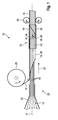
- Figure 1 schematically depicts a device 10 with which a method of placing an airbag 12 in a protective sheath 14 can be carried out.
- the device 10 comprises a connection device 16 for connecting opposing free edges 18, 20 of a protective sheet 14'.
- a connection device 16 for connecting opposing free edges 18, 20 of a protective sheet 14'.
- the one-ply, band-shaped material for the protection and fixation of the airbag 12 is termed protective sheet 14', as long as it is not yet connected along its opposing, free longitudinal edges.
- protective sheath 14 the material which now is tube-like, will be referred to as protective sheath 14.
- the device 10 comprises a feeding device 22 for feeding the protective sheet 14' as well as the airbag 12 to the connection device 16.
- the feeding device 22 comprises a profile rail 24 which compresses the airbag 12, pre-folded in an accordion-like manner, into its desired and folded condition, a supply reel 26 which has the band-shaped protective sheet 14' wound thereon, a profile structural component 28 which will be explained in more detail in the description of Figures 2 to 4 , and a drive 30 capable of moving the protective sheath 14 together with the airbag 12 along a longitudinal axis A.
- the driving direction of the protective sheath 14/protective sheet 14' and of the airbag 12 is indicated in Figure 1 by an arrow 32.
- connection device 16 is arranged in the region of the profile structural component 28.
- the connection device 16 is a sewing machine, which is indicated symbolically in Figure 1 by a needle 34.
- the connection device 16 may also be a gluing or welding device, for instance, gluing or welding the opposing free edges 18, 20 of the protective sheet 14' with each other.
- the edges 18, 20 of the protective sheath 14 are connected with each other at a point of connection 36 by the connection device 16; in the present example they are sewn to each other, reference symbol 38 in Figure 1 giving an indication to a corresponding seam.
- this seam 38 is realized discontinuously, so that after placing the airbag 12 in the protective sheath 14 fastening tabs provided on the airbag 12 can be passed through the seam gaps, in order to fasten the airbag 12 to an airbag module part, for instance.
- the device 10 as well as the method (which is described below) of placing the airbag 12 in the protective sheath 14 is particularly suited for side airbags which in the deployed state cover a vehicular side wall at least in part.
- Such airbags 12 have a longitudinal axis A in the vehicular longitudinal direction and are pre-folded in axial direction mostly in an accordion-like manner, with corresponding folds 40 being marked in Figure 1 .
- the profile structural component 28 as a central component of the feeding device 22 will be explained in more detail in the following by means of Figures 2 to 4 .
- the profile structural component 28 has an inner profile element 42 and an outer profile element 44 surrounding the inner profile element 42, the pre-folded airbag 12 being guided in the inner profile element 42 and the protective sheet 14' being guided between the inner and outer profile elements 42, 44 (cf. Figures 3 and 4 ).
- Figure 2 shows the top view of the profile structural component 28 from Figure 1 in detail.
- the outer profile element 44 is composed of two pieces 46, 48, this two-part configuration being essentially due to circumstances concerning production.
- the inner profile element 42 can be seen, which extends in the outer profile element 44, with the contour of the inner profile elements 42 within the outer profile elements 44 being partly indicated in broken line.
- This contour of the inner profile elements 42 makes clear that the pre-folded airbag 12 is separated from the protective sheet 14' at the point of connection 36, at which the free edges 18, 20 of the protective sheet 14' are connected with each other, this separation being established by the inner profile element 42, more precisely by a flange-like protrusion 50 of the profile element 42. In this way, any inadvertent connecting, in particular sewing the protective sheet 14' with the airbag 12 is excluded, and a desired deployment of the airbag in the case of activation will be ensured.
- Figure 3 shows a perspective view of the profile structural component 28, the outer profile element 44 having an open cross-section.
- a first part 46 of the outer profile element 44 has an essentially U-shaped cross-section with two legs 52, 54.
- the protective sheet 14' is laid around the pre-folded airbag 12, to be more precise, around the inner profile element 42 in which the pre-folded airbag 12 is guided.
- the free longitudinal edges 18, 20 are situated in the region of the free ends of the legs 52, 54.
- the distance between the legs 52, 54 decreases, so that the free edges 18, 20 of the protective sheet 14' are moved towards each other.
- a second part 48 of the outer profile element 44 has an open box-type cross-section with two end flanges 56, 58.
- the free edges 18, 20 of the protective sheet 14' are guided via the legs 52, 54 of the first part 46 between the end flanges 56, 58 of the second part 48 of the outer profile element 44.
- an opening 60 for the needle 34 of a sewing machine (cf. Figure 1 ) is provided in the end flanges 56, 58.
- the opening 60 generally represents the point of connection 36 at which the edges 18, 20 of the protective sheet 14' are connected with each other, so that the tube-shaped protective sheath 14 will be produced.
- the protective sheath 14 together with airbag 12 accommodated therein leaves the profile structural component 28.
- Figure 4 shows only the inner profile element 44 of the profile structural component 28 in a perspective view. In this illustration the flange-like protrusion 50 can be seen particularly well, separating the airbag 12 from the protective sheet 14 at the point of connection 36' (cf. Figure 1 ).
- the drive 30 Relating to the driving direction 32 of the airbag 12 the drive 30 is provided according to Figure 1 behind the profile structural component 28, this drive moving the protective sheath 14/protective sheet 14' together with the pre-folded airbag 12 in axial direction through the feeding device 22.
- the connection device 16 As the connection device 16 is firmly connected with the feeding device 22, the airbag 12 together with the protective sheet 14' or protective sheath 14 will move also relative to the connection device 16 in axial direction.
- the drive 30 feeds the protective sheet 14' via the feeding device 22 to the connection device 16 (together with the airbag 12) in such a manner that the connection device 16 can connect the free edges 18, 20 in the desired way. If the edges 18, 20 are being sewn, a continual supply is of advantage, whereas in the case of gluing or welding the edges 18, 20 a discontinued, stepwise supply would be conceivable.
- the drive 30, the feeding device 22 and the connection device 16 are connected with each other in such a manner that, on the one hand, they constitute a structural unit, but on the other hand they are adapted to each other such that they constitute a functional unit.
- the method of placing the airbag 12 in the protective sheath 14 may thus be summarized as follows: At first a pre-folded airbag as well as a protective sheet 14' are provided, the pre-folded airbag being fed to the profile structural component 28 by the profile rail 24 and the protective sheet 14' being fed to the same through the supply reel 26. By means of the profile structural component 28 the protective sheet 14' is laid around the pre-folded airbag 12. In the same working operation the opposing free edges 18, 20 of the protective sheet 14' are connected with each other such that the tube-like protective sheath 14 is produced which surrounds the airbag.
- both the airbag 12 and the protective sheet 14' merely perform a combined movement in axial direction, in order to place the airbag 12 in the protective sheath 14.
- the method can be carried out with low manual amount of work; this is why it is particularly efficient and inexpensive.
- the airbag 12 is separated from the protective sheet 14' or protective sheath 14 during the manufacture of the connection between the edges 18, 20 of the protective sheet 14' preferably by the profile structural component 28.
Landscapes
- Engineering & Computer Science (AREA)
- Mechanical Engineering (AREA)
- Air Bags (AREA)
Abstract
a) an airbag (12) and a protective sheet (14') are provided;
b) the airbag (12) is pre-folded;
c) the protective sheet (14') is laid around the pre-folded airbag (12); and
d) opposing free edges (18, 20) of the protective sheet (14') are connected with each other such that a tube-like protective sheath (14) is produced which surrounds the airbag (12);
the steps c) and d) being carried out in one working operation.
Description
- The invention relates to a method of placing an airbag in a protective sheath as well as to a device for carrying out this method.
- It is generally known to place airbags of vehicle occupant restraint systems in protective sheaths which, on the one hand, protect the airbag and, on the other hand, keep it in a compressed and folded state. The airbag together with the protective sheath is usually fastened to a gas generator and/or a housing, in order to constitute a pre-assembled airbag module. In order to allow the airbag to deploy in the desired manner, the protective sheath is provided in most cases with a predetermined breaking point or a tear seam, tearing open upon activation of the airbag module.
- In prior art, in particular side airbags covering a vehicle side wall at least in portions in the deployed state, are often pre-folded in vehicular longitudinal direction in an accordion-like manner and are placed in a tube-like protective sheath.
-
DE 102 55 119 B3 discloses a method of placing such an airbag in an elongated encasement, with the pre-folded airbag firstly being inserted in a profile rail having a U-shaped cross-section; after this, the profile rail together with the airbag is inserted in a prefabricated, elongate tube encasement. This tube encasement finally is withdrawn from the profile rail together with the pre-folded airbag, so that the airbag is placed in the encasement as desired. As the encasing material at first is available as a one-ply band, it has to be prefabricated at first to a tube-like envelope. This separate work step as well as the subsequent introducing and withdrawing of the profile rail or the encasement in the longitudinal direction of the tube-like envelope make the described method labor-intensive and costly. - It is therefore the object of invention to provide a simplified method of placing an airbag in a protective sheath.
- This object is achieved by a method according to the invention comprising the following steps:
- a) an airbag and a protective sheet are provided;
- b) the airbag is pre-folded;
- c) the protective sheet is laid around the pre-folded airbag; and
- d) opposing free edges of the protective sheet are connected with each other such that a tube-like protective sheath is produced which surrounds the airbag;
- As the protective sheet is laid around the pre-folded airbag almost simultaneously in one work step and is connected so as to form a protective sheath, preferably by sewing, the prefabrication of the protective sheath as well as the expensive insertion and extraction of the profile rail or protective sheath can be omitted. Accordingly, the method of placing the airbag in the protective sheath becomes more efficient on the whole and thus more cost-effective.
- In a variant of the method the opposing free edges of the protective sheet are connected with each other, while the pre-folded airbag is separated from the protective sheet by a profile structural component. It is ensured thereby that the protective sheet is not inadvertently connected with portions of the pre-folded airbag and that the deployment of the airbag upon activation of the airbag module is not hindered.
- In a further variant of the method the airbag has a longitudinal axis, and a connection device is preferably provided for connecting the opposing free edges of the protective sheet, the airbag together with the protective sheet being moved relative to the connection device in axial direction during the combined working operation of the steps c) and d). The airbag thus is placed in the protective sheath by a one-time, linear movement in axial direction, which sheath is fabricated from the protective sheet not before, but during this movement. A prefabrication of the protective sheath can be omitted accordingly, just as the axial introduction of a profile rail in the protective sheath and the subsequent axial extraction of the protective sheath (together with the airbag) from the profile rail.
- The invention further includes a device for carrying out the described method, the device comprising a connection device for connecting the opposing free edges of the protective sheet, and a feeding device for feeding the protective sheet and the airbag, being inserted therein, to the connection device. After only a one-time run through the device according to the invention, the protective sheet and the airbag are processed so as to form a packet, which can be installed in the prefabricated form without any further working steps.
- The feeding device preferably includes a profile structural component by means of which the protective sheet is positioned relative to the airbag. Such a profile structural component for positioning the protective sheet can be manufactured at low expenses, whereby a low-cost changeover from the conventional method to the new method of placing an airbag in the protective sheath will be made possible.
- Special embodiments of the invention and the advantages thereof will be apparent from the sub-claims.
- The invention will now be described by means of a preferred embodiment which is illustrated in the attached drawings and in which:
-
Figure 1 shows the device according to the invention for carrying out the method according to the invention in a schematic top view; -
Figure 2 shows a profile structural component of the device according to the invention in a top view; -
Figure 3 shows the profile structural component according toFigure 2 in a perspective view; and -
Figure 4 shows an inner profile part of the profile structural component ofFigure 3 in a perspective view. -
Figure 1 schematically depicts adevice 10 with which a method of placing anairbag 12 in aprotective sheath 14 can be carried out. - The
device 10 comprises a connection device 16 for connecting opposing free edges 18, 20 of aprotective sheet 14'. In this context, the one-ply, band-shaped material for the protection and fixation of theairbag 12 is termedprotective sheet 14', as long as it is not yet connected along its opposing, free longitudinal edges. When the edges 18, 20 are connected, the material which now is tube-like, will be referred to asprotective sheath 14. - Apart from the connection device 16 the
device 10 comprises afeeding device 22 for feeding theprotective sheet 14' as well as theairbag 12 to the connection device 16. According toFigure 1 , thefeeding device 22 comprises aprofile rail 24 which compresses theairbag 12, pre-folded in an accordion-like manner, into its desired and folded condition, asupply reel 26 which has the band-shapedprotective sheet 14' wound thereon, a profilestructural component 28 which will be explained in more detail in the description ofFigures 2 to 4 , and adrive 30 capable of moving theprotective sheath 14 together with theairbag 12 along a longitudinal axis A. The driving direction of theprotective sheath 14/protective sheet 14' and of theairbag 12 is indicated inFigure 1 by anarrow 32. - The connection device 16 is arranged in the region of the profile
structural component 28. In the example embodiment which is illustrated, the connection device 16 is a sewing machine, which is indicated symbolically inFigure 1 by a needle 34. In alternative variants of the embodiment the connection device 16 may also be a gluing or welding device, for instance, gluing or welding the opposing free edges 18, 20 of theprotective sheet 14' with each other. - The edges 18, 20 of the
protective sheath 14 are connected with each other at a point of connection 36 by the connection device 16; in the present example they are sewn to each other,reference symbol 38 inFigure 1 giving an indication to a corresponding seam. In some variants of the embodiment thisseam 38 is realized discontinuously, so that after placing theairbag 12 in theprotective sheath 14 fastening tabs provided on theairbag 12 can be passed through the seam gaps, in order to fasten theairbag 12 to an airbag module part, for instance. - The
device 10 as well as the method (which is described below) of placing theairbag 12 in theprotective sheath 14 is particularly suited for side airbags which in the deployed state cover a vehicular side wall at least in part.Such airbags 12 have a longitudinal axis A in the vehicular longitudinal direction and are pre-folded in axial direction mostly in an accordion-like manner, withcorresponding folds 40 being marked inFigure 1 . - The profile
structural component 28 as a central component of thefeeding device 22 will be explained in more detail in the following by means ofFigures 2 to 4 . The profilestructural component 28 has aninner profile element 42 and anouter profile element 44 surrounding theinner profile element 42, thepre-folded airbag 12 being guided in theinner profile element 42 and theprotective sheet 14' being guided between the inner andouter profile elements 42, 44 (cf.Figures 3 and 4 ). -
Figure 2 shows the top view of the profilestructural component 28 fromFigure 1 in detail. Theouter profile element 44 is composed of twopieces inner profile element 42 can be seen, which extends in theouter profile element 44, with the contour of theinner profile elements 42 within theouter profile elements 44 being partly indicated in broken line. - This contour of the
inner profile elements 42, illustrated as a broken line, makes clear that thepre-folded airbag 12 is separated from theprotective sheet 14' at the point of connection 36, at which the free edges 18, 20 of theprotective sheet 14' are connected with each other, this separation being established by theinner profile element 42, more precisely by a flange-like protrusion 50 of theprofile element 42. In this way, any inadvertent connecting, in particular sewing theprotective sheet 14' with theairbag 12 is excluded, and a desired deployment of the airbag in the case of activation will be ensured. -
Figure 3 shows a perspective view of the profilestructural component 28, theouter profile element 44 having an open cross-section. Afirst part 46 of theouter profile element 44 has an essentially U-shaped cross-section with twolegs protective sheet 14' is laid around thepre-folded airbag 12, to be more precise, around theinner profile element 42 in which thepre-folded airbag 12 is guided. In this process, the free longitudinal edges 18, 20 are situated in the region of the free ends of thelegs driving direction 32 of theprotective sheet 14' or theairbag 12, the distance between thelegs protective sheet 14' are moved towards each other. - A
second part 48 of theouter profile element 44 has an open box-type cross-section with twoend flanges protective sheet 14' are guided via thelegs first part 46 between theend flanges second part 48 of theouter profile element 44. For sewing the edges 18, 20, an opening 60 for the needle 34 of a sewing machine (cf.Figure 1 ) is provided in theend flanges protective sheet 14' are connected with each other, so that the tube-shapedprotective sheath 14 will be produced. - Subsequently, the
protective sheath 14 together withairbag 12 accommodated therein leaves the profilestructural component 28. -
Figure 4 shows only theinner profile element 44 of the profilestructural component 28 in a perspective view. In this illustration the flange-like protrusion 50 can be seen particularly well, separating theairbag 12 from theprotective sheet 14 at the point of connection 36' (cf.Figure 1 ). - Relating to the driving
direction 32 of theairbag 12 thedrive 30 is provided according toFigure 1 behind the profilestructural component 28, this drive moving theprotective sheath 14/protective sheet 14' together with thepre-folded airbag 12 in axial direction through thefeeding device 22. As the connection device 16 is firmly connected with thefeeding device 22, theairbag 12 together with theprotective sheet 14' orprotective sheath 14 will move also relative to the connection device 16 in axial direction. - In this process, the
drive 30 feeds theprotective sheet 14' via thefeeding device 22 to the connection device 16 (together with the airbag 12) in such a manner that the connection device 16 can connect the free edges 18, 20 in the desired way. If the edges 18, 20 are being sewn, a continual supply is of advantage, whereas in the case of gluing or welding the edges 18, 20 a discontinued, stepwise supply would be conceivable. - All in all, the
drive 30, thefeeding device 22 and the connection device 16 are connected with each other in such a manner that, on the one hand, they constitute a structural unit, but on the other hand they are adapted to each other such that they constitute a functional unit. - The method of placing the
airbag 12 in theprotective sheath 14 may thus be summarized as follows: At first a pre-folded airbag as well as aprotective sheet 14' are provided, the pre-folded airbag being fed to the profilestructural component 28 by theprofile rail 24 and theprotective sheet 14' being fed to the same through thesupply reel 26. By means of the profilestructural component 28 theprotective sheet 14' is laid around thepre-folded airbag 12. In the same working operation the opposing free edges 18, 20 of theprotective sheet 14' are connected with each other such that the tube-likeprotective sheath 14 is produced which surrounds the airbag. The term "in the same working operation" means here that both theairbag 12 and theprotective sheet 14' merely perform a combined movement in axial direction, in order to place theairbag 12 in theprotective sheath 14. Thereby the method can be carried out with low manual amount of work; this is why it is particularly efficient and inexpensive. For avoiding an undesired connection between theairbag 12 and theprotective sheath 14, theairbag 12 is separated from theprotective sheet 14' orprotective sheath 14 during the manufacture of the connection between the edges 18, 20 of theprotective sheet 14' preferably by the profilestructural component 28.
Claims (10)
- A method of placing an airbag (12) in a protective sheath (14), comprising the following steps:a) an airbag (12) and a protective sheet (14') are provided;b) the airbag (12) is pre-folded;c) the protective sheet (14') is laid around the pre-folded airbag (12); andd) opposing free edges (18, 20) of the protective sheet (14') are connected with each other such that a tube-like protective sheath (14) is produced which surrounds the airbag (12);the steps c) and d) being carried out in one working operation.
- The method according to claim 1, characterized in that the opposing free edges (18, 20) of the protective sheet (14') are sewn in step d).
- The method according to claim 1 or 2, characterized in that the opposing free edges (18, 20) of the protective sheet (14') are connected while the pre-folded airbag (12) is separated from the protective sheet (14') by a profile structural component (28).
- The method according to any of the preceding claims, characterized in that the pre-folded airbag (12) has a longitudinal axis (A) and a connection device (16) is provided for connecting the opposing free edges (18, 20) of the protective sheet (14'), the airbag (12) together with the protective sheet (14') being moved relative to the connection device (16) in an axial direction during the combined working operation of the steps c) and d).
- A device for carrying out the method according to any of the preceding claims, characterized bya connection device (16) for connecting the opposing free edges (18, 20) of the protective sheet (14'), anda feeding device (22) for feeding the protective sheet (14') and the airbag (12), being inserted therein, to the connection device (16).
- The device according to claim 5, characterized in that the connection device (16) is a sewing machine.
- The device according to claim 5 or 6, characterized in that the feeding device (22) includes a profile structural component (28) by means of which the protective sheet (14') is positioned relative to the airbag (12).
- The device according to claim 7, characterized in that the profile structural component (28) has an inner profile element (42) and an outer profile element (44) surrounding the inner profile element (42), the pre-folded airbag (12) being guided in the inner profile element (42) and the protective sheet (14') being guided between the inner and outer profile elements (42, 44).
- The device according to claim 8, characterized in that the inner profile element (42) has a closed cross-section and the outer profile element (44) has an open cross-section.
- The device according to any of the preceding claims, characterized in that the connection device (16) and the feeding device (22) form a structural unit and are functionally adapted to each other.
Priority Applications (1)
| Application Number | Priority Date | Filing Date | Title |
|---|---|---|---|
| EP08017635A EP2174844A1 (en) | 2008-10-08 | 2008-10-08 | Method and device for placing an airbag in a protective sheath |
Applications Claiming Priority (1)
| Application Number | Priority Date | Filing Date | Title |
|---|---|---|---|
| EP08017635A EP2174844A1 (en) | 2008-10-08 | 2008-10-08 | Method and device for placing an airbag in a protective sheath |
Publications (1)
| Publication Number | Publication Date |
|---|---|
| EP2174844A1 true EP2174844A1 (en) | 2010-04-14 |
Family
ID=40383581
Family Applications (1)
| Application Number | Title | Priority Date | Filing Date |
|---|---|---|---|
| EP08017635A Withdrawn EP2174844A1 (en) | 2008-10-08 | 2008-10-08 | Method and device for placing an airbag in a protective sheath |
Country Status (1)
| Country | Link |
|---|---|
| EP (1) | EP2174844A1 (en) |
Citations (4)
| Publication number | Priority date | Publication date | Assignee | Title |
|---|---|---|---|---|
| EP1179455A2 (en) * | 2000-08-07 | 2002-02-13 | Takata-Petri AG | Method for folding an airbag and device for carrying out this method |
| US20020078664A1 (en) * | 2000-12-21 | 2002-06-27 | Arwood Robert L. | Airbag folding apparatus and method of folding |
| WO2003013913A1 (en) * | 2001-08-10 | 2003-02-20 | Dalphi Metal España, S.A. | Method of folding and packing an inflatable curtain airbag |
| DE10255119B3 (en) | 2002-11-26 | 2004-05-06 | Berger Seiba-Technotex Gmbh & Co | Airbag encasing process for airbag to be fitted in vehicle involves gripping airbag, compressing it, fitting it in U-form rail, inserting it and rail in casing and removing rail |
-
2008
- 2008-10-08 EP EP08017635A patent/EP2174844A1/en not_active Withdrawn
Patent Citations (4)
| Publication number | Priority date | Publication date | Assignee | Title |
|---|---|---|---|---|
| EP1179455A2 (en) * | 2000-08-07 | 2002-02-13 | Takata-Petri AG | Method for folding an airbag and device for carrying out this method |
| US20020078664A1 (en) * | 2000-12-21 | 2002-06-27 | Arwood Robert L. | Airbag folding apparatus and method of folding |
| WO2003013913A1 (en) * | 2001-08-10 | 2003-02-20 | Dalphi Metal España, S.A. | Method of folding and packing an inflatable curtain airbag |
| DE10255119B3 (en) | 2002-11-26 | 2004-05-06 | Berger Seiba-Technotex Gmbh & Co | Airbag encasing process for airbag to be fitted in vehicle involves gripping airbag, compressing it, fitting it in U-form rail, inserting it and rail in casing and removing rail |
Similar Documents
| Publication | Publication Date | Title |
|---|---|---|
| EP3476667B1 (en) | Curtain airbag device | |
| KR102596089B1 (en) | Roof airbag apparatus | |
| EP1558470B1 (en) | Shrink wrap for inflatable curtain package | |
| CN101934773B (en) | Airbag mounting assemblies with double-locking wrappers | |
| US8047570B2 (en) | Airbag arrangement for a vehicle occupant restraint system and a method for the production of an airbag module | |
| US6334627B1 (en) | Variable-volume air bag for an airbag module | |
| US7954842B2 (en) | Airbag restraint device for occupants of a vehicle | |
| EP3287327B1 (en) | Curtain airbag device | |
| WO1998019893A1 (en) | Arrangement and construction of crew protective device for automobile | |
| US20170120853A1 (en) | Airbag cushion protectors and related methods | |
| CN102219010B (en) | Safety airbag installation system | |
| CN102770314A (en) | Airbag device for a passenger protection system of a vehicle and method for producing same | |
| EP1183169B1 (en) | A method of assembling an airbag module | |
| EP2174844A1 (en) | Method and device for placing an airbag in a protective sheath | |
| KR101224729B1 (en) | Side airbag installation in a backrest of a motor vehicle seat | |
| KR101070147B1 (en) | Automotive Curtain Airbag Module | |
| CN106029451B (en) | Install the envelope | |
| US11772594B2 (en) | Vehicle roof airbag with binding parts | |
| CN102405156A (en) | Airbag module covered by protective cover | |
| CN102248929A (en) | Inflation airbag device | |
| US20060163855A1 (en) | Gas bag module | |
| WO2021028424A1 (en) | Airbag module for a motor vehicle | |
| CN108569243B (en) | Method for producing an airbag module for a vehicle occupant restraint system and airbag module | |
| WO2025042930A1 (en) | Curtain airbag with package maintaining structure | |
| JP2016083981A (en) | Airbag device |
Legal Events
| Date | Code | Title | Description |
|---|---|---|---|
| PUAI | Public reference made under article 153(3) epc to a published international application that has entered the european phase |
Free format text: ORIGINAL CODE: 0009012 |
|
| AK | Designated contracting states |
Kind code of ref document: A1 Designated state(s): AT BE BG CH CY CZ DE DK EE ES FI FR GB GR HR HU IE IS IT LI LT LU LV MC MT NL NO PL PT RO SE SI SK TR |
|
| AX | Request for extension of the european patent |
Extension state: AL BA MK RS |
|
| 17P | Request for examination filed |
Effective date: 20101014 |
|
| AKX | Designation fees paid |
Designated state(s): AT BE BG CH CY CZ DE DK EE ES FI FR GB GR HR HU IE IS IT LI LT LU LV MC MT NL NO PL PT RO SE SI SK TR |
|
| 17Q | First examination report despatched |
Effective date: 20110105 |
|
| RIC1 | Information provided on ipc code assigned before grant |
Ipc: B60R 21/201 20110101AFI20120704BHEP Ipc: B60R 21/237 20060101ALI20120704BHEP |
|
| GRAP | Despatch of communication of intention to grant a patent |
Free format text: ORIGINAL CODE: EPIDOSNIGR1 |
|
| RIN1 | Information on inventor provided before grant (corrected) |
Inventor name: ZAGOROWSKI MACIEJ Inventor name: LARA, WLODZIMIERZ Inventor name: NORBERCIAK TOMASZ Inventor name: BEDNAREK ADAM Inventor name: OGINSKI, ARTUR Inventor name: SITEK, KRZYSZTOF |
|
| GRAS | Grant fee paid |
Free format text: ORIGINAL CODE: EPIDOSNIGR3 |
|
| STAA | Information on the status of an ep patent application or granted ep patent |
Free format text: STATUS: THE APPLICATION IS DEEMED TO BE WITHDRAWN |
|
| 18D | Application deemed to be withdrawn |
Effective date: 20130409 |