EP2172843A1 - Method and systems for restarting a flight control system - Google Patents
Method and systems for restarting a flight control system Download PDFInfo
- Publication number
- EP2172843A1 EP2172843A1 EP20090171333 EP09171333A EP2172843A1 EP 2172843 A1 EP2172843 A1 EP 2172843A1 EP 20090171333 EP20090171333 EP 20090171333 EP 09171333 A EP09171333 A EP 09171333A EP 2172843 A1 EP2172843 A1 EP 2172843A1
- Authority
- EP
- European Patent Office
- Prior art keywords
- ram
- executable program
- sector
- processor
- control system
- Prior art date
- Legal status (The legal status is an assumption and is not a legal conclusion. Google has not performed a legal analysis and makes no representation as to the accuracy of the status listed.)
- Granted
Links
Images



Classifications
-
- G—PHYSICS
- G06—COMPUTING OR CALCULATING; COUNTING
- G06F—ELECTRIC DIGITAL DATA PROCESSING
- G06F11/00—Error detection; Error correction; Monitoring
- G06F11/07—Responding to the occurrence of a fault, e.g. fault tolerance
- G06F11/16—Error detection or correction of the data by redundancy in hardware
- G06F11/1666—Error detection or correction of the data by redundancy in hardware where the redundant component is memory or memory area
-
- G—PHYSICS
- G06—COMPUTING OR CALCULATING; COUNTING
- G06F—ELECTRIC DIGITAL DATA PROCESSING
- G06F11/00—Error detection; Error correction; Monitoring
- G06F11/07—Responding to the occurrence of a fault, e.g. fault tolerance
- G06F11/14—Error detection or correction of the data by redundancy in operations
- G06F11/1402—Saving, restoring, recovering or retrying
- G06F11/1415—Saving, restoring, recovering or retrying at system level
- G06F11/1438—Restarting or rejuvenating
Definitions
- controller 110 does not receive an operator input, but rather determines the operations of flight control surfaces of the aircraft based on, for example, a pre-programmed flight plan and inputs from sensor 112.
- Actuators 116 move the flight control surfaces of the aircraft according to flight controller 110 instructions.
Landscapes
- Engineering & Computer Science (AREA)
- Theoretical Computer Science (AREA)
- Quality & Reliability (AREA)
- Physics & Mathematics (AREA)
- General Engineering & Computer Science (AREA)
- General Physics & Mathematics (AREA)
- Retry When Errors Occur (AREA)
- Stored Programmes (AREA)
- Safety Devices In Control Systems (AREA)
- Traffic Control Systems (AREA)
Abstract
Description
- The field of the invention relates generally to flight control systems, and more specifically, to a method and systems for rapid recovery after a flight control system error or fault.
- At least some known aircraft include a control system that includes a digital computer. A flight control system receives inputs from sensors and/or a pilot and in response provides control signals to flight control components of the aircraft. An example of a flight control system included in some known aircraft is a fly-by wire system. In an aircraft that includes a fly-by wire system, a pilot's movements of cockpit controls are not transferred to a corresponding flight control surface of the aircraft through a mechanical coupling, such as hydraulics or cables. But rather, the pilot's movements of cockpit controls are converted by sensors into electronic signals that are transferred to the flight control system computer. The flight control system computer provides actuators coupled to the flight control surfaces of the aircraft with operating instructions. Fly-by wire systems also typically include sensors that provide the flight control system computer with data that is combined with the pilot inputs to determine operation of the flight control surfaces, for example an electronic stability system.
- A flight control system may also be included in an unmanned vehicle. A flight control system in an unmanned aircraft receives electronic signals, for example from a remote location or from a pre-programmed flight-plan, and combines those electronic signals with information from sensors to determine operation of the flight control surfaces.
- Uninterrupted operation of the computer and/or rapid recovery from a computer error or fault facilitates reliance on a computer for flight control.
- In one aspect, a method for rapid restarting of a flight control system, wherein the flight control system comprises a processor, is described. The method includes storing at least one executable program on a memory device and copying the at least one executable program to a first random access memory (RAM) sector and a second RAM sector of a RAM memory device at a predetermined time. The method also includes copying the at least one executable program from the second RAM sector to the first RAM sector upon a restart of the processor and reinitializing processor operation by executing the at least one executable program copied from the second RAM sector to the first RAM sector.
- In another aspect, a flight control system is described. The flight control system includes at least one sensor/input device configured to collect data and a flight controller coupled to the at least one sensor/input device. The flight controller includes a random access memory (RAM) device configured to store at least one executable program in a first RAM sector and a second RAM sector and a processor configured to execute the at least one executable program from the first RAM sector to process the sensor/input device data, and to output operational instructions. The flight control system also includes at least one actuator coupled to the flight controller. The actuator is configured to receive and execute the operational instructions.
- In yet another aspect, a flight controller is described. The flight controller includes a random access memory (RAM) device including a first RAM sector and a second RAM sector, wherein a first copy of at least one executable program is stored in the first RAM sector and a second copy of the at least one executable program is stored in the second RAM sector. The flight controller also includes a processor configured to execute the at least one executable program from the first RAM sector.
- There follows a detailed description of embodiments of the invention by way of example only with reference to the accompanying drawings, in which:
-
Figure 1 is a block diagram of an exemplary flight control system; -
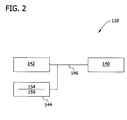
Figure 2 is a block diagram of an exemplary embodiment of a flight controller; -
Figure 3 is an alternative embodiment of the flight controller shown inFigure 2 ; -
Figure 4 is an exemplary timing diagram of operations of a flight control system; and -
Figure 5 is a flowchart of an exemplary method for rapid restarting of a flight control system. - The following detailed description illustrates embodiments of the invention by way of example and not by way of limitation. It is contemplated that the invention has general application to rapid restarting of a plant control system that reduces interruptions to plant operation in industrial, commercial, and residential applications.
- As used herein, an element or step recited in the singular and proceeded with the word "a" or "an" should be understood as not excluding plural elements or steps, unless such exclusion is explicitly recited. Furthermore, references to "one embodiment" of the present invention are not intended to be interpreted as excluding the existence of additional embodiments that also incorporate the recited features.
-
Figure 1 is a block diagram of an exemplaryflight control system 100. In the exemplary embodiment,flight control system 100 includes aflight controller 110, asensor 112, an input/output (I/O)device 114, and anactuator 116.Sensor 112 providesflight controller 110 with data, for example, current flight information, aircraft information, and weather-related information.Flight controller 110 receives and processes the data, resulting in flight control instructions provided to I/O device 114, and toactuator 116 where action is taken in accordance with flight control instructions. Although illustrated as including asingle sensor 112, a single I/O device 114, and asingle actuator 116,system 100 may include any number of sensors, I/O devices, and actuators that allowsystem 100 to function as described herein. - In a specific embodiment, when an operator moves an input device (not shown in
Figure 1 ) coupled tosensor 112,sensor 112 transfers the operator input toflight controller 110. For example, an operator's movement of a flight stick (not shown inFigure 1 ) are received bysensor 112 and transferred toflight controller 110.Controller 110 determines the operations of flight control surfaces of the aircraft (not shown inFigure 1 ) that correspond to the operator input.Controller 110 may also combine the operator input with any other sensor inputs preprogrammed to correspond to the selected operator input, for example, weather-related inputs, altitude input and/or aircraft speed input. In other embodiments,controller 110 does not receive an operator input, but rather determines the operations of flight control surfaces of the aircraft based on, for example, a pre-programmed flight plan and inputs fromsensor 112.Actuators 116 move the flight control surfaces of the aircraft according toflight controller 110 instructions. -
Figure 2 is a block diagram of an exemplary embodiment offlight controller 110. In the exemplary embodiment,flight controller 110 includes aprocessor 140, a read only memory (ROM)device 142, and a random access memory (RAM)device 144. In the exemplary embodiment,ROM memory device 142,RAM memory device 144, andprocessor 140 are coupled by amemory bus 146. In some examples,ROM memory device 142 is a Flash memory device, however,ROM memory device 142 may be any memory device that allowsflight controller 110 to function as described herein. The above memory types are exemplary only, and are thus not limiting as to the types of memory usable withinflight controller 110. - At least one of
ROM device 142 andRAM device 144 store, andprocessor 140 executes, at least one executable program. In the exemplary embodiment, the executable program includes an operating system and at least one application. The operating system controls allocation of the resources of system 100 (shown inFigure 1 ) and applications control, for example, operation of the aircraft. The operating system includes executable code and data structures used to implement the resource allocation services of the operating system. The applications include executable code and data structures used to, for example, determine flight instructions. In certain embodiments, the operating system is a real time operating system (RTOS). The RTOS facilitates deterministic behavior, where responses to events are expected to occur within a predetermined period of time after the occurrence of the event. The RTOS may be stored onROM memory device 142 and/orRAM memory device 144, and is accessible toprocessor 140 overmemory bus 146. -
RAM memory device 144 includes one continuous bank of RAM. The one continuous bank of RAM includes a first sector on the low address space where executable programs are copied to and where they execute from. The first sector of RAM is referred to herein as a low-RAM 150. The one continuous bank of RAM also includes a second sector on the high address space where programs are placed in transient status. The second sector of RAM is referred to herein as a high-RAM 154. The programs are copied to high-RAM 154 and low-RAM 150 from eitherROM device 142 or from a target host system (not shown inFigure 2 ). Upon the occurrence of an event and/or fault, programs are copied from high-RAM 154 to low-RAM 150 and executed from low-RAM 150. In the exemplary embodiment,processor 140 controls read/write operations betweenROM device 142, low-RAM 150, and high-RAM 154. -
Figure 3 is an alternative embodiment offlight controller 110. Components shared between the exemplary embodiment of flight controller 110 (shown inFigure 2 ) and the alternative embodiment of flight controller 110 (shown inFigure 3 ) are identified with identical reference numerals. In the alternative embodiment,flight controller 110 includes a direct memory access (DMA)engine 162.DMA engine 162 performs read/write operations betweenROM device 142, low-RAM 150, and high-RAM 154 independently ofprocessor 140.DMA engine 162 facilitates rapid transfer of data betweenmemory devices processor 140 of these data transfer tasks. -
Figure 4 is an exemplary timing diagram 170 offlight controller 110 operation. Timing diagram 170 illustrates acontrol loop 172 offlight controller 110 operations that are repeated, to continuously determine the operating instructions that maintain the operation of the aircraft.Flight controller 110 operations include obtaining 180 inputs, processing 182 the inputs, and sending 184 outputs. In the exemplary embodiment,flight controller 110 obtains 180 inputs from, for example, sensor 112 (shown inFigure 1 ), and sends 184 outputs to, for example, I/O device 114 (shown inFigure 1 ), which in turn effects operation of actuator 116 (shown inFigure 1 ). The length ofcontrol loop 172 is referred to herein as acomputing frame 186.Computing frame 186 is dependent upon flight control requirements. For example, a large passenger aircraft may not demand flight control signals to maintain stability as frequently as a fighter jet. In some embodiments, for example a fighter jet, theoperations computing frame 186 may be from one ms to five-hundred ms in length, however, these computing frames 186 are given as examples only, and are not meant to be limiting. - Any interruptions in
control loop 172 may interrupt operation offlight control system 100. Reducing the effect of interruptions incontrol loop 172 facilitates reducing interruptions to operation offlight control system 100. For example, a software error may interrupt operation ofprocessor 140 and therefore controlloop 172. The software error may be, for example, an event such as a divide-by-zero error, a data access exception, or an instruction access exception in the executable program running onprocessor 140. The software error may be any event that interrupts operation ofprocessor 140 and therefore interruptscontrol loop 172. A restart ofprocessor 140 typically will returnprocessor 140 to normal operation by eliminating a software error. However, during a processor reset,control loop 172 is interrupted. The shorter the length ofcomputing frame 186, the greater the affect of an error event onflight controller 110, due tomore frames 186 ofcontrol loop 172 passing whileprocessor 140 is returning to normal operation. -
Figure 5 is aflowchart 200 of an exemplary method for rapid restarting of a flight control system, for example, flight control system 100 (shown inFigure 1 ). The exemplary method includes storing 210 an executable program in, for example, ROM device 142 (shown inFigure 2 ). The executable program includes program text and read only data. More specifically, in the exemplary embodiment, the executable program includes an operating system code and application code. The method also includes copying 212 the executable program during startup of flight controller 110 (shown inFigure 1 ). Copying 212 the executable program during flight controller startup includes copying the executable program stored inROM device 142 to a low-RAM and also to a high-RAM. For example, the executable program is copied to low-RAM 150 of RAM memory device 144 (shown inFigure 2 ), and also copied to high-RAM 154 of RAM memory device 144 (shown inFigure 2 ). - Once copied 212 to low-RAM and to high-RAM, a processor executes 214 the executable program from low-RAM 150. As described above, an event, for example, a software error or fault, may be resolved by restarting
processor 140. Restartingprocessor 140 includes reinitializing the executable program to eliminate the processor error or fault. The exemplary method includes copying 216 the executable program from high-RAM 154 to low-RAM 150 andreinitializing 218processor 140 using the executable program transferred to low-RAM 150.Reinitializing 218processor 140 using the copied executable program facilitates restartingprocessor 140 with the original executable program, free of errors that may have entered the executable program during execution before the processor error or fault. - In some embodiments, a full restart of
processor 140 is not needed and certain steps in the restart process can be eliminated when restartingprocessor 140 after the occurrence of a software error/fault. For example, if not needed to overcome the software error/fault, setup of the memory management unit (MMU) may be skipped. The rapid transfer of the executable program between high-RAM 154 and low-RAM 150 facilitates reducing the restart time ofprocessor 140. Furthermore, a reduced restart time facilitates reducing interruption of processor 140 (shown inFigure 2 ) operation which may reduce a period of time that control loop 172 (shown inFigure 4 ) is not cycling through operations. Since interruptingcontrol loop 172 may interrupt flight control, a rapid restart ofprocessor 140 is advantageous. - In the exemplary embodiment, copying 212 is controlled by
processor 140 using read/write commands. In an alternative embodiment, copying 212 is controlled independently ofprocessor 140 by, for example, DMA engine 162 (shown inFigure 3 ). Controlling copying 212 independently fromprocessor 140 facilitates reducing the load onprocessor 140 as well as decreasing executable program transfer times. - Described herein are exemplary methods and systems for rapid restarting of a flight control system. More specifically, the method described herein can be utilized to store and access an executable program from a section of RAM in the event of a software fault/error.
- The systems and methods described herein facilitate efficient and economical operation of a flight control system. Facilitating a reduction in a processor restart time may facilitate reducing the effects of a software error on aircraft operation. A technical effect of the methods and systems described herein includes facilitating reduced restart times of a flight control system processor.
- Although the systems and methods described and/or illustrated herein are described and/or illustrated with respect to aircraft and flight control systems, practice of the systems and methods described and/or illustrated herein is not limited to aircraft or flight control systems. Rather, the systems and methods described and/or illustrated herein are applicable to any plant or vehicle where uninterrupted operation is desirable.
- Exemplary embodiments of systems and methods are described and/or illustrated herein in detail. The systems and methods are not limited to the specific embodiments described herein, but rather, components of each system, as well as steps of each method, may be utilized independently and separately from other components and steps described herein. Each component, and each method step, can also be used in combination with other components and/or method steps.
- The term processor, as used herein, refers to central processing units, microprocessors, microcontrollers, reduced instruction set circuits (RISC), application specific integrated circuits (ASIC), logic circuits, and any other circuit or processor capable of executing the functions described herein.
- This written description uses examples to disclose the invention, including the best mode, and also to enable any person skilled in the art to practice the invention, including making and using any devices or systems and performing any incorporated methods. The patentable scope of the invention is defined by the claims, and may include other examples that occur to those skilled in the art. Such other examples are intended to be within the scope of the claims if they have structural elements that do not differ from the literal language of the claims, or if they include equivalent structural elements with insubstantial differences from the literal languages of the claims.
- For completeness, various aspects of the invention are now set out in the following numbered clauses:
- 1. A method for rapid restarting of a flight control system, wherein the flight control system comprises a processor, said method comprising:
- storing at least one executable program on a memory device;
- copying the at least one executable program to a first random access memory (RAM) sector and a second RAM sector of a RAM memory device at a predetermined time;
- copying the at least one executable program from the second RAM sector to the first RAM sector upon a restart of the processor; and
- reinitializing processor operation by executing the at least one executable program copied from the second RAM sector to the first RAM sector.
- 2. A method in accordance with clause 1, further comprising executing the at least one executable program from the first RAM sector.
- 3. A method in accordance with clause 1, wherein copying the at least one executable program is controlled by at least one of a direct memory access (DMA) engine and the processor.
- 4. A method in accordance with clause 1, wherein the first RAM sector is a low-RAM sector on a continuous bank of RAM memory and the second RAM sector is a high-RAM sector on the continuous bank of RAM memory.
- 5. A method in accordance with clause 1, wherein copying the at least one executable program at a predetermined time comprises copying the at least one executable program during startup of the flight control system.
- 6. A method in accordance with clause 1, wherein storing at least one executable program comprises storing a real time operating system (RTOS) on the memory device.
- 7. A method in accordance with clause 1, wherein copying the at least one executable program from the second RAM sector to the first RAM sector comprises copying the at least one executable program after the occurrence of a processor software fault/error.
- 8. A flight control system comprising:
- at least one sensor configured to collect data;
- a flight controller coupled to said at least one sensor, said flight controller comprising:
- a random access memory (RAM) device configured to store at least one executable program in a first RAM sector and a second RAM sector of said RAM device; and
- a processor configured to execute the at least one executable program from the first RAM sector to process the sensor data, and to output operational instructions; and
- at least one actuator coupled to said flight controller, said actuator configured to receive and execute the operational instructions.
- 9. A flight control system in accordance with clause 8, wherein said at least one sensor further comprises an input device configured to receive inputs provided by an operator of the flight control system.
- 10. A flight control system in accordance with clause 8, wherein said at least one sensor/input device, said flight controller, and said at least one actuator are coupled over a memory bus.
- 11. A flight control system in accordance with clause 8, further comprising a read only memory (ROM) device configured to store the at least one executable program.
- 12. A flight control system in accordance with clause 11, wherein said processor is further configured to:
- control transfer of the at least one executable program from the ROM device to the RAM device at a predetermined time, and
- control transfer of the at least one executable program from the second RAM sector to the first RAM sector after a processor fault/error.
- 13. A flight control system in accordance with clause 12, wherein said predetermined time is at a startup of said flight controller.
- 14. A flight control system in accordance with clause 8, wherein said flight controller further comprises a direct memory access (DMA) engine configured to:
- control transfer of the at least one executable program from the ROM device to the RAM device at startup of said flight controller, and
- control transfer of the at least one executable program from the second RAM sector to the first RAM sector after a processor fault/error.
- 15. A flight controller comprising:
- a random access memory (RAM) device comprising a first RAM sector and a second RAM sector, wherein a first copy of at least one executable program is stored in the first RAM sector, and a second copy of the at least one executable program is stored in the second RAM sector; and
- a processor configured to execute the at least one executable program from the first RAM sector.
- 16. A flight controller in accordance with clause 15, wherein said processor is further configured to control transfer of the at least one executable program from the second RAM sector to the first RAM sector after a processor fault/error.
- 17. A flight controller in accordance with clause 15, further comprising a read only memory (ROM) device configured to store the at least one executable program.
- 18. A flight controller in accordance with clause 17, wherein said processor is further configured to control transfer of the at least one executable program from the ROM device to the first RAM sector and to the second RAM sector of the RAM device at a predetermined time.
- 19. A flight controller in accordance with clause 18, wherein the predetermined time is at a startup of said flight controller.
- 20. A flight controller in accordance with clause 18 further comprising a direct memory access (DMA) engine configured to control transfer of at least one of:
- the at least one executable program from the second RAM sector to the first RAM sector after a processor fault/error; and
- the at least one executable program from the ROM device to the RAM device at startup of said flight controller.
Claims (15)
- A flight control system (100) comprising:at least one sensor (112) configured to collect data;a flight controller (110) coupled to said at least one sensor, said flight controller comprising:a random access memory (RAM) device (144) configured to store at least one executable program in a first RAM sector and a second RAM sector of said RAM device; anda processor (140) configured to execute the at least one executable program from the first RAM sector to process the sensor data, and to output operational instructions; andat least one actuator (116) coupled to said flight controller, said actuator configured to receive and execute the operational instructions.
- A flight control system (100) in accordance with Claim 1, wherein said at least one sensor (112) further comprises an input device (114) configured to receive inputs provided by an operator of the flight control system.
- A flight control system (100) in accordance with Claim 1 or 2, wherein said at least one sensor/input device (114), said flight controller (110), and said at least one actuator (116) are coupled over a memory bus (146).
- A flight control system (100) in accordance with any of the preceding claims, further comprising a read only memory (ROM) device (142) configured to store the at least one executable program.
- A flight control system (100) in accordance with Claim 4, wherein said processor (140) is further configured to:control transfer of the at least one executable program from the ROM device (142) to the RAM device (144) at a predetermined time, andcontrol transfer of the at least one executable program from the second RAM sector to the first RAM sector after a processor fault/error.
- A flight control system (100) in accordance with Claim 5, wherein said predetermined time is at a startup of said flight controller (110).
- A flight control system (100) in accordance with any of the preceding claims, wherein said flight controller (110) further comprises a direct memory access (DMA) engine (162) configured to:control transfer of the at least one executable program from the ROM device (142) to the RAM device (144) at startup of said flight controller (110), andcontrol transfer of the at least one executable program from the second RAM sector to the first RAM sector after a processor fault/error.
- A flight controller (110) comprising:a random access memory (RAM) device (144) comprising a first RAM sector and a second RAM sector, wherein a first copy of at least one executable program is stored in the first RAM sector, and a second copy of the at least one executable program is stored in the second RAM sector; anda processor (140) configured to execute the at least one executable program from the first RAM sector.
- A flight controller (110) in accordance with Claim 8, wherein said processor (140) is further configured to control transfer of the at least one executable program from the second RAM sector to the first RAM sector after a processor fault/error.
- A flight controller (110) in accordance with Claim 8 or 9, further comprising a read only memory (ROM) device (142) configured to store the at least one executable program.
- A method for rapid restarting of a flight control system, wherein the flight control system comprises a processor, said method comprising:storing at least one executable program on a memory device;copying the at least one executable program to a first random access memory (RAM) sector and a second RAM sector of a RAM memory device at a predetermined time;copying the at least one executable program from the second RAM sector to the first RAM sector upon a restart of the processor; andreinitializing processor operation by executing the at least one executable program copied from the second RAM sector to the first RAM sector.
- A method in accordance with Claim 11, further comprising executing the at least one executable program from the first RAM sector.
- A method in accordance with Claim 11 or 12, wherein copying the at least one executable program is controlled by at least one of a direct memory access (DMA) engine and the processor.
- A method in accordance with any of Claims 11 to 13, wherein the first RAM sector is a low-RAM sector on a continuous bank of RAM memory and the second RAM sector is a high-RAM sector on the continuous bank of RAM memory.
- A method in accordance with any of Claims 11 to 14, wherein copying the at least one executable program at a predetermined time comprises copying the at least one executable program during startup of the flight control system.
Priority Applications (1)
| Application Number | Priority Date | Filing Date | Title |
|---|---|---|---|
| EP22150669.4A EP4002123B1 (en) | 2008-09-30 | 2009-09-25 | Method and systems for restarting a flight control system |
Applications Claiming Priority (1)
| Application Number | Priority Date | Filing Date | Title |
|---|---|---|---|
| US12/242,357 US8209526B2 (en) | 2008-09-30 | 2008-09-30 | Method and systems for restarting a flight control system |
Related Child Applications (2)
| Application Number | Title | Priority Date | Filing Date |
|---|---|---|---|
| EP22150669.4A Division-Into EP4002123B1 (en) | 2008-09-30 | 2009-09-25 | Method and systems for restarting a flight control system |
| EP22150669.4A Division EP4002123B1 (en) | 2008-09-30 | 2009-09-25 | Method and systems for restarting a flight control system |
Publications (2)
| Publication Number | Publication Date |
|---|---|
| EP2172843A1 true EP2172843A1 (en) | 2010-04-07 |
| EP2172843B1 EP2172843B1 (en) | 2022-06-15 |
Family
ID=41381933
Family Applications (2)
| Application Number | Title | Priority Date | Filing Date |
|---|---|---|---|
| EP22150669.4A Active EP4002123B1 (en) | 2008-09-30 | 2009-09-25 | Method and systems for restarting a flight control system |
| EP09171333.9A Active EP2172843B1 (en) | 2008-09-30 | 2009-09-25 | Method and systems for restarting a flight control system |
Family Applications Before (1)
| Application Number | Title | Priority Date | Filing Date |
|---|---|---|---|
| EP22150669.4A Active EP4002123B1 (en) | 2008-09-30 | 2009-09-25 | Method and systems for restarting a flight control system |
Country Status (6)
| Country | Link |
|---|---|
| US (1) | US8209526B2 (en) |
| EP (2) | EP4002123B1 (en) |
| JP (1) | JP5632602B2 (en) |
| CN (1) | CN101713970B (en) |
| BR (1) | BRPI0903553A2 (en) |
| CA (1) | CA2680807C (en) |
Cited By (1)
| Publication number | Priority date | Publication date | Assignee | Title |
|---|---|---|---|---|
| GB2518671A (en) * | 2013-09-30 | 2015-04-01 | St Microelectronics Res & Dev | Multiple Processor System |
Families Citing this family (16)
| Publication number | Priority date | Publication date | Assignee | Title |
|---|---|---|---|---|
| US8275954B2 (en) * | 2010-01-08 | 2012-09-25 | International Business Machines Corporation | Using DMA for copying performance counter data to memory |
| CN102884477B (en) | 2010-03-31 | 2015-11-25 | 株式会社半导体能源研究所 | Liquid crystal display and driving method thereof |
| CN102072063A (en) * | 2011-01-04 | 2011-05-25 | 北京航空航天大学 | Encounter-starting airstart system of aircraft engine |
| FR2972712B1 (en) * | 2011-03-16 | 2014-09-05 | Airbus Operations Sas | MONITORING A FLIGHT CONTROL ACTUATOR OF AN AIRCRAFT |
| US10357709B2 (en) | 2016-09-30 | 2019-07-23 | Sony Interactive Entertainment Inc. | Unmanned aerial vehicle movement via environmental airflow |
| US10850838B2 (en) | 2016-09-30 | 2020-12-01 | Sony Interactive Entertainment Inc. | UAV battery form factor and insertion/ejection methodologies |
| US10377484B2 (en) | 2016-09-30 | 2019-08-13 | Sony Interactive Entertainment Inc. | UAV positional anchors |
| US10410320B2 (en) | 2016-09-30 | 2019-09-10 | Sony Interactive Entertainment Inc. | Course profiling and sharing |
| US10679511B2 (en) | 2016-09-30 | 2020-06-09 | Sony Interactive Entertainment Inc. | Collision detection and avoidance |
| US10210905B2 (en) * | 2016-09-30 | 2019-02-19 | Sony Interactive Entertainment Inc. | Remote controlled object macro and autopilot system |
| US10336469B2 (en) | 2016-09-30 | 2019-07-02 | Sony Interactive Entertainment Inc. | Unmanned aerial vehicle movement via environmental interactions |
| US11125561B2 (en) | 2016-09-30 | 2021-09-21 | Sony Interactive Entertainment Inc. | Steering assist |
| US10416669B2 (en) | 2016-09-30 | 2019-09-17 | Sony Interactive Entertainment Inc. | Mechanical effects by way of software or real world engagement |
| US10067736B2 (en) | 2016-09-30 | 2018-09-04 | Sony Interactive Entertainment Inc. | Proximity based noise and chat |
| CN111427327A (en) * | 2019-12-27 | 2020-07-17 | 湖北航天飞行器研究所 | Protection method for abnormal restart of aircraft control software |
| CN116654271B (en) * | 2023-06-15 | 2026-02-13 | 广东汇天航空航天科技有限公司 | Methods and devices for handling electric drive malfunctions in aircraft and electric aircraft |
Citations (6)
| Publication number | Priority date | Publication date | Assignee | Title |
|---|---|---|---|---|
| US5363502A (en) * | 1990-06-08 | 1994-11-08 | Hitachi, Ltd. | Hot stand-by method and computer system for implementing hot stand-by method |
| US6195695B1 (en) * | 1998-10-27 | 2001-02-27 | International Business Machines Corporation | Data processing system and method for recovering from system crashes |
| WO2002073505A1 (en) * | 2001-03-12 | 2002-09-19 | Honeywell International, Inc. | Method of recovering a flight critical computer after a radiation event |
| US6665813B1 (en) * | 2000-08-03 | 2003-12-16 | International Business Machines Corporation | Method and apparatus for updateable flash memory design and recovery with minimal redundancy |
| US6970890B1 (en) * | 2000-12-20 | 2005-11-29 | Bitmicro Networks, Inc. | Method and apparatus for data recovery |
| WO2007005790A2 (en) * | 2005-06-30 | 2007-01-11 | Sling Media, Inc. | Firmware update for consumer electronic device |
Family Cites Families (11)
| Publication number | Priority date | Publication date | Assignee | Title |
|---|---|---|---|---|
| GB1441816A (en) * | 1973-07-18 | 1976-07-07 | Int Computers Ltd | Electronic digital data processing systems |
| US4622667A (en) * | 1984-11-27 | 1986-11-11 | Sperry Corporation | Digital fail operational automatic flight control system utilizing redundant dissimilar data processing |
| US5109521A (en) * | 1986-09-08 | 1992-04-28 | Compaq Computer Corporation | System for relocating dynamic memory address space having received microprocessor program steps from non-volatile memory to address space of non-volatile memory |
| JPH0474241A (en) * | 1990-07-17 | 1992-03-09 | Nec Corp | Fault processing system |
| US5313625A (en) * | 1991-07-30 | 1994-05-17 | Honeywell Inc. | Fault recoverable computer system |
| US6804752B2 (en) * | 2001-04-02 | 2004-10-12 | Delphi Technologies, Inc. | Event data protection method for a flash programmable microprocessor-based control module |
| US6813527B2 (en) * | 2002-11-20 | 2004-11-02 | Honeywell International Inc. | High integrity control system architecture using digital computing platforms with rapid recovery |
| US20050132121A1 (en) * | 2003-12-16 | 2005-06-16 | Wind River Systems, Inc. | Partitioned operating system tool |
| US7395394B2 (en) * | 2006-02-03 | 2008-07-01 | Hewlett-Packard Development Company, L.P. | Computer operating system with selective restriction of memory write operations |
| JP2008065434A (en) * | 2006-09-05 | 2008-03-21 | Matsushita Electric Ind Co Ltd | Program start control device |
| US20090054045A1 (en) * | 2007-08-22 | 2009-02-26 | Slawomir Zakrzewski | Device and Method for Warm Boot Persistence |
-
2008
- 2008-09-30 US US12/242,357 patent/US8209526B2/en active Active
-
2009
- 2009-09-16 BR BRPI0903553-2A patent/BRPI0903553A2/en active Search and Examination
- 2009-09-24 CA CA2680807A patent/CA2680807C/en not_active Expired - Fee Related
- 2009-09-25 EP EP22150669.4A patent/EP4002123B1/en active Active
- 2009-09-25 JP JP2009219864A patent/JP5632602B2/en not_active Expired - Fee Related
- 2009-09-25 EP EP09171333.9A patent/EP2172843B1/en active Active
- 2009-09-30 CN CN200910178775.7A patent/CN101713970B/en active Active
Patent Citations (6)
| Publication number | Priority date | Publication date | Assignee | Title |
|---|---|---|---|---|
| US5363502A (en) * | 1990-06-08 | 1994-11-08 | Hitachi, Ltd. | Hot stand-by method and computer system for implementing hot stand-by method |
| US6195695B1 (en) * | 1998-10-27 | 2001-02-27 | International Business Machines Corporation | Data processing system and method for recovering from system crashes |
| US6665813B1 (en) * | 2000-08-03 | 2003-12-16 | International Business Machines Corporation | Method and apparatus for updateable flash memory design and recovery with minimal redundancy |
| US6970890B1 (en) * | 2000-12-20 | 2005-11-29 | Bitmicro Networks, Inc. | Method and apparatus for data recovery |
| WO2002073505A1 (en) * | 2001-03-12 | 2002-09-19 | Honeywell International, Inc. | Method of recovering a flight critical computer after a radiation event |
| WO2007005790A2 (en) * | 2005-06-30 | 2007-01-11 | Sling Media, Inc. | Firmware update for consumer electronic device |
Cited By (2)
| Publication number | Priority date | Publication date | Assignee | Title |
|---|---|---|---|---|
| GB2518671A (en) * | 2013-09-30 | 2015-04-01 | St Microelectronics Res & Dev | Multiple Processor System |
| US9594792B2 (en) | 2013-09-30 | 2017-03-14 | Stmicroelectronics (Research & Development) Limited | Multiple processor system |
Also Published As
| Publication number | Publication date |
|---|---|
| US8209526B2 (en) | 2012-06-26 |
| CA2680807C (en) | 2017-10-17 |
| EP2172843B1 (en) | 2022-06-15 |
| JP5632602B2 (en) | 2014-11-26 |
| CA2680807A1 (en) | 2010-03-30 |
| CN101713970B (en) | 2014-02-26 |
| EP4002123A1 (en) | 2022-05-25 |
| JP2010083480A (en) | 2010-04-15 |
| EP4002123B1 (en) | 2023-07-12 |
| BRPI0903553A2 (en) | 2010-06-01 |
| CN101713970A (en) | 2010-05-26 |
| US20100083038A1 (en) | 2010-04-01 |
Similar Documents
| Publication | Publication Date | Title |
|---|---|---|
| US8209526B2 (en) | Method and systems for restarting a flight control system | |
| EP1563352B1 (en) | High integrity control system architecture using digital computing platforms with rapid recovery | |
| EP3301526B1 (en) | Controller, control method, and program | |
| JP6853883B2 (en) | controller | |
| CN102640119B (en) | Method for operating a processor | |
| AU2003294628A1 (en) | Redundant automation system for controlling a technical device, and method for operating one such automation system | |
| US10379931B2 (en) | Computer system | |
| EP4390687A1 (en) | Scheduling of duplicate threads | |
| CN102508746A (en) | Management method for triple configurable fault-tolerant computer system | |
| CN111338265A (en) | Heterogeneous redundancy unmanned aerial vehicle autopilot | |
| CN112000078A (en) | A state recovery method for redundant flight control computer after failure | |
| CN104062896B (en) | The redundancy implementation method of a kind of periodicity control synchronization signal | |
| CN108733502B (en) | Method for error recognition in an operating system | |
| KR102471314B1 (en) | A System and Method of Health Management for On-the-fly Repairing of Order Violation in Airborne Software | |
| EP2207070A1 (en) | Field control device and field control method | |
| Majumder et al. | Reliable flight control system architecture for agile airborne platforms: an asymmetric multiprocessing approach | |
| JP4102814B2 (en) | I/O CONTROL DEVICE, INFORMATION CONTROL DEVICE, AND INFORMATION CONTROL METHOD | |
| CN118575167A (en) | Computer, control method, and control program | |
| US20220214993A1 (en) | Electronic computing device | |
| CN111788555A (en) | External exception handling | |
| WO2013057769A1 (en) | Information processing device, control method for information processing device and control program | |
| CN118227278A (en) | Scheduling of repeated threads | |
| CN104199760A (en) | Method for monitoring computer crash with EC SCI function | |
| Eickhoff | Onboard Software Dynamic Architecture | |
| JPWO2013057769A1 (en) | Information processing apparatus, control method for information processing apparatus, and control program |
Legal Events
| Date | Code | Title | Description |
|---|---|---|---|
| PUAI | Public reference made under article 153(3) epc to a published international application that has entered the european phase |
Free format text: ORIGINAL CODE: 0009012 |
|
| AK | Designated contracting states |
Kind code of ref document: A1 Designated state(s): AT BE BG CH CY CZ DE DK EE ES FI FR GB GR HR HU IE IS IT LI LT LU LV MC MK MT NL NO PL PT RO SE SI SK SM TR |
|
| AX | Request for extension of the european patent |
Extension state: AL BA RS |
|
| 17P | Request for examination filed |
Effective date: 20101007 |
|
| 17Q | First examination report despatched |
Effective date: 20101029 |
|
| APBK | Appeal reference recorded |
Free format text: ORIGINAL CODE: EPIDOSNREFNE |
|
| APBN | Date of receipt of notice of appeal recorded |
Free format text: ORIGINAL CODE: EPIDOSNNOA2E |
|
| APBR | Date of receipt of statement of grounds of appeal recorded |
Free format text: ORIGINAL CODE: EPIDOSNNOA3E |
|
| APAF | Appeal reference modified |
Free format text: ORIGINAL CODE: EPIDOSCREFNE |
|
| APAF | Appeal reference modified |
Free format text: ORIGINAL CODE: EPIDOSCREFNE |
|
| APBT | Appeal procedure closed |
Free format text: ORIGINAL CODE: EPIDOSNNOA9E |
|
| RIC1 | Information provided on ipc code assigned before grant |
Ipc: G06F 11/14 20060101ALI20210728BHEP Ipc: G06F 11/16 20060101AFI20210728BHEP |
|
| GRAP | Despatch of communication of intention to grant a patent |
Free format text: ORIGINAL CODE: EPIDOSNIGR1 |
|
| STAA | Information on the status of an ep patent application or granted ep patent |
Free format text: STATUS: GRANT OF PATENT IS INTENDED |
|
| INTG | Intention to grant announced |
Effective date: 20210916 |
|
| GRAJ | Information related to disapproval of communication of intention to grant by the applicant or resumption of examination proceedings by the epo deleted |
Free format text: ORIGINAL CODE: EPIDOSDIGR1 |
|
| STAA | Information on the status of an ep patent application or granted ep patent |
Free format text: STATUS: EXAMINATION IS IN PROGRESS |
|
| INTC | Intention to grant announced (deleted) | ||
| GRAP | Despatch of communication of intention to grant a patent |
Free format text: ORIGINAL CODE: EPIDOSNIGR1 |
|
| STAA | Information on the status of an ep patent application or granted ep patent |
Free format text: STATUS: GRANT OF PATENT IS INTENDED |
|
| INTG | Intention to grant announced |
Effective date: 20220307 |
|
| GRAS | Grant fee paid |
Free format text: ORIGINAL CODE: EPIDOSNIGR3 |
|
| GRAA | (expected) grant |
Free format text: ORIGINAL CODE: 0009210 |
|
| STAA | Information on the status of an ep patent application or granted ep patent |
Free format text: STATUS: THE PATENT HAS BEEN GRANTED |
|
| AK | Designated contracting states |
Kind code of ref document: B1 Designated state(s): AT BE BG CH CY CZ DE DK EE ES FI FR GB GR HR HU IE IS IT LI LT LU LV MC MK MT NL NO PL PT RO SE SI SK SM TR |
|
| REG | Reference to a national code |
Ref country code: CH Ref legal event code: EP Ref country code: GB Ref legal event code: FG4D |
|
| REG | Reference to a national code |
Ref country code: IE Ref legal event code: FG4D |
|
| REG | Reference to a national code |
Ref country code: DE Ref legal event code: R096 Ref document number: 602009064478 Country of ref document: DE |
|
| REG | Reference to a national code |
Ref country code: AT Ref legal event code: REF Ref document number: 1498800 Country of ref document: AT Kind code of ref document: T Effective date: 20220715 |
|
| REG | Reference to a national code |
Ref country code: LT Ref legal event code: MG9D |
|
| REG | Reference to a national code |
Ref country code: NL Ref legal event code: MP Effective date: 20220615 |
|
| PG25 | Lapsed in a contracting state [announced via postgrant information from national office to epo] |
Ref country code: SE Free format text: LAPSE BECAUSE OF FAILURE TO SUBMIT A TRANSLATION OF THE DESCRIPTION OR TO PAY THE FEE WITHIN THE PRESCRIBED TIME-LIMIT Effective date: 20220615 Ref country code: NO Free format text: LAPSE BECAUSE OF FAILURE TO SUBMIT A TRANSLATION OF THE DESCRIPTION OR TO PAY THE FEE WITHIN THE PRESCRIBED TIME-LIMIT Effective date: 20220915 Ref country code: LT Free format text: LAPSE BECAUSE OF FAILURE TO SUBMIT A TRANSLATION OF THE DESCRIPTION OR TO PAY THE FEE WITHIN THE PRESCRIBED TIME-LIMIT Effective date: 20220615 Ref country code: HR Free format text: LAPSE BECAUSE OF FAILURE TO SUBMIT A TRANSLATION OF THE DESCRIPTION OR TO PAY THE FEE WITHIN THE PRESCRIBED TIME-LIMIT Effective date: 20220615 Ref country code: GR Free format text: LAPSE BECAUSE OF FAILURE TO SUBMIT A TRANSLATION OF THE DESCRIPTION OR TO PAY THE FEE WITHIN THE PRESCRIBED TIME-LIMIT Effective date: 20220916 Ref country code: FI Free format text: LAPSE BECAUSE OF FAILURE TO SUBMIT A TRANSLATION OF THE DESCRIPTION OR TO PAY THE FEE WITHIN THE PRESCRIBED TIME-LIMIT Effective date: 20220615 Ref country code: BG Free format text: LAPSE BECAUSE OF FAILURE TO SUBMIT A TRANSLATION OF THE DESCRIPTION OR TO PAY THE FEE WITHIN THE PRESCRIBED TIME-LIMIT Effective date: 20220915 |
|
| REG | Reference to a national code |
Ref country code: AT Ref legal event code: MK05 Ref document number: 1498800 Country of ref document: AT Kind code of ref document: T Effective date: 20220615 |
|
| PG25 | Lapsed in a contracting state [announced via postgrant information from national office to epo] |
Ref country code: LV Free format text: LAPSE BECAUSE OF FAILURE TO SUBMIT A TRANSLATION OF THE DESCRIPTION OR TO PAY THE FEE WITHIN THE PRESCRIBED TIME-LIMIT Effective date: 20220615 |
|
| PG25 | Lapsed in a contracting state [announced via postgrant information from national office to epo] |
Ref country code: NL Free format text: LAPSE BECAUSE OF FAILURE TO SUBMIT A TRANSLATION OF THE DESCRIPTION OR TO PAY THE FEE WITHIN THE PRESCRIBED TIME-LIMIT Effective date: 20220615 |
|
| PG25 | Lapsed in a contracting state [announced via postgrant information from national office to epo] |
Ref country code: SM Free format text: LAPSE BECAUSE OF FAILURE TO SUBMIT A TRANSLATION OF THE DESCRIPTION OR TO PAY THE FEE WITHIN THE PRESCRIBED TIME-LIMIT Effective date: 20220615 Ref country code: SK Free format text: LAPSE BECAUSE OF FAILURE TO SUBMIT A TRANSLATION OF THE DESCRIPTION OR TO PAY THE FEE WITHIN THE PRESCRIBED TIME-LIMIT Effective date: 20220615 Ref country code: RO Free format text: LAPSE BECAUSE OF FAILURE TO SUBMIT A TRANSLATION OF THE DESCRIPTION OR TO PAY THE FEE WITHIN THE PRESCRIBED TIME-LIMIT Effective date: 20220615 Ref country code: PT Free format text: LAPSE BECAUSE OF FAILURE TO SUBMIT A TRANSLATION OF THE DESCRIPTION OR TO PAY THE FEE WITHIN THE PRESCRIBED TIME-LIMIT Effective date: 20221017 Ref country code: ES Free format text: LAPSE BECAUSE OF FAILURE TO SUBMIT A TRANSLATION OF THE DESCRIPTION OR TO PAY THE FEE WITHIN THE PRESCRIBED TIME-LIMIT Effective date: 20220615 Ref country code: EE Free format text: LAPSE BECAUSE OF FAILURE TO SUBMIT A TRANSLATION OF THE DESCRIPTION OR TO PAY THE FEE WITHIN THE PRESCRIBED TIME-LIMIT Effective date: 20220615 Ref country code: CZ Free format text: LAPSE BECAUSE OF FAILURE TO SUBMIT A TRANSLATION OF THE DESCRIPTION OR TO PAY THE FEE WITHIN THE PRESCRIBED TIME-LIMIT Effective date: 20220615 Ref country code: AT Free format text: LAPSE BECAUSE OF FAILURE TO SUBMIT A TRANSLATION OF THE DESCRIPTION OR TO PAY THE FEE WITHIN THE PRESCRIBED TIME-LIMIT Effective date: 20220615 |
|
| PG25 | Lapsed in a contracting state [announced via postgrant information from national office to epo] |
Ref country code: PL Free format text: LAPSE BECAUSE OF FAILURE TO SUBMIT A TRANSLATION OF THE DESCRIPTION OR TO PAY THE FEE WITHIN THE PRESCRIBED TIME-LIMIT Effective date: 20220615 Ref country code: IS Free format text: LAPSE BECAUSE OF FAILURE TO SUBMIT A TRANSLATION OF THE DESCRIPTION OR TO PAY THE FEE WITHIN THE PRESCRIBED TIME-LIMIT Effective date: 20221015 |
|
| REG | Reference to a national code |
Ref country code: DE Ref legal event code: R097 Ref document number: 602009064478 Country of ref document: DE |
|
| PLBE | No opposition filed within time limit |
Free format text: ORIGINAL CODE: 0009261 |
|
| STAA | Information on the status of an ep patent application or granted ep patent |
Free format text: STATUS: NO OPPOSITION FILED WITHIN TIME LIMIT |
|
| PG25 | Lapsed in a contracting state [announced via postgrant information from national office to epo] |
Ref country code: MC Free format text: LAPSE BECAUSE OF FAILURE TO SUBMIT A TRANSLATION OF THE DESCRIPTION OR TO PAY THE FEE WITHIN THE PRESCRIBED TIME-LIMIT Effective date: 20220615 Ref country code: DK Free format text: LAPSE BECAUSE OF FAILURE TO SUBMIT A TRANSLATION OF THE DESCRIPTION OR TO PAY THE FEE WITHIN THE PRESCRIBED TIME-LIMIT Effective date: 20220615 |
|
| REG | Reference to a national code |
Ref country code: CH Ref legal event code: PL |
|
| 26N | No opposition filed |
Effective date: 20230316 |
|
| REG | Reference to a national code |
Ref country code: BE Ref legal event code: MM Effective date: 20220930 |
|
| PG25 | Lapsed in a contracting state [announced via postgrant information from national office to epo] |
Ref country code: SI Free format text: LAPSE BECAUSE OF FAILURE TO SUBMIT A TRANSLATION OF THE DESCRIPTION OR TO PAY THE FEE WITHIN THE PRESCRIBED TIME-LIMIT Effective date: 20220615 |
|
| P01 | Opt-out of the competence of the unified patent court (upc) registered |
Effective date: 20230414 |
|
| PG25 | Lapsed in a contracting state [announced via postgrant information from national office to epo] |
Ref country code: LU Free format text: LAPSE BECAUSE OF NON-PAYMENT OF DUE FEES Effective date: 20220925 |
|
| PG25 | Lapsed in a contracting state [announced via postgrant information from national office to epo] |
Ref country code: LI Free format text: LAPSE BECAUSE OF NON-PAYMENT OF DUE FEES Effective date: 20220930 Ref country code: IE Free format text: LAPSE BECAUSE OF NON-PAYMENT OF DUE FEES Effective date: 20220925 Ref country code: CH Free format text: LAPSE BECAUSE OF NON-PAYMENT OF DUE FEES Effective date: 20220930 |
|
| PG25 | Lapsed in a contracting state [announced via postgrant information from national office to epo] |
Ref country code: BE Free format text: LAPSE BECAUSE OF NON-PAYMENT OF DUE FEES Effective date: 20220930 |
|
| PG25 | Lapsed in a contracting state [announced via postgrant information from national office to epo] |
Ref country code: IT Free format text: LAPSE BECAUSE OF FAILURE TO SUBMIT A TRANSLATION OF THE DESCRIPTION OR TO PAY THE FEE WITHIN THE PRESCRIBED TIME-LIMIT Effective date: 20220615 |
|
| PG25 | Lapsed in a contracting state [announced via postgrant information from national office to epo] |
Ref country code: HU Free format text: LAPSE BECAUSE OF FAILURE TO SUBMIT A TRANSLATION OF THE DESCRIPTION OR TO PAY THE FEE WITHIN THE PRESCRIBED TIME-LIMIT; INVALID AB INITIO Effective date: 20090925 |
|
| PG25 | Lapsed in a contracting state [announced via postgrant information from national office to epo] |
Ref country code: CY Free format text: LAPSE BECAUSE OF FAILURE TO SUBMIT A TRANSLATION OF THE DESCRIPTION OR TO PAY THE FEE WITHIN THE PRESCRIBED TIME-LIMIT Effective date: 20220615 |
|
| PG25 | Lapsed in a contracting state [announced via postgrant information from national office to epo] |
Ref country code: MK Free format text: LAPSE BECAUSE OF FAILURE TO SUBMIT A TRANSLATION OF THE DESCRIPTION OR TO PAY THE FEE WITHIN THE PRESCRIBED TIME-LIMIT Effective date: 20220615 |
|
| PG25 | Lapsed in a contracting state [announced via postgrant information from national office to epo] |
Ref country code: MT Free format text: LAPSE BECAUSE OF FAILURE TO SUBMIT A TRANSLATION OF THE DESCRIPTION OR TO PAY THE FEE WITHIN THE PRESCRIBED TIME-LIMIT Effective date: 20220615 |
|
| PG25 | Lapsed in a contracting state [announced via postgrant information from national office to epo] |
Ref country code: BG Free format text: LAPSE BECAUSE OF FAILURE TO SUBMIT A TRANSLATION OF THE DESCRIPTION OR TO PAY THE FEE WITHIN THE PRESCRIBED TIME-LIMIT Effective date: 20220615 |
|
| PG25 | Lapsed in a contracting state [announced via postgrant information from national office to epo] |
Ref country code: BG Free format text: LAPSE BECAUSE OF FAILURE TO SUBMIT A TRANSLATION OF THE DESCRIPTION OR TO PAY THE FEE WITHIN THE PRESCRIBED TIME-LIMIT Effective date: 20220615 |
|
| PGFP | Annual fee paid to national office [announced via postgrant information from national office to epo] |
Ref country code: DE Payment date: 20250820 Year of fee payment: 17 |
|
| PGFP | Annual fee paid to national office [announced via postgrant information from national office to epo] |
Ref country code: GB Payment date: 20250820 Year of fee payment: 17 |
|
| PGFP | Annual fee paid to national office [announced via postgrant information from national office to epo] |
Ref country code: FR Payment date: 20250820 Year of fee payment: 17 |
|
| PG25 | Lapsed in a contracting state [announced via postgrant information from national office to epo] |
Ref country code: TR Free format text: LAPSE BECAUSE OF FAILURE TO SUBMIT A TRANSLATION OF THE DESCRIPTION OR TO PAY THE FEE WITHIN THE PRESCRIBED TIME-LIMIT Effective date: 20220615 |