EP2172707A2 - Off center combustor liner - Google Patents
Off center combustor liner Download PDFInfo
- Publication number
- EP2172707A2 EP2172707A2 EP09171719A EP09171719A EP2172707A2 EP 2172707 A2 EP2172707 A2 EP 2172707A2 EP 09171719 A EP09171719 A EP 09171719A EP 09171719 A EP09171719 A EP 09171719A EP 2172707 A2 EP2172707 A2 EP 2172707A2
- Authority
- EP
- European Patent Office
- Prior art keywords
- liner
- center
- combustor
- fuel
- air
- Prior art date
- Legal status (The legal status is an assumption and is not a legal conclusion. Google has not performed a legal analysis and makes no representation as to the accuracy of the status listed.)
- Withdrawn
Links
- 230000007704 transition Effects 0.000 claims abstract description 27
- 239000000446 fuel Substances 0.000 claims description 26
- 238000002485 combustion reaction Methods 0.000 claims description 14
- 238000000034 method Methods 0.000 claims description 5
- 239000007789 gas Substances 0.000 description 11
- MWUXSHHQAYIFBG-UHFFFAOYSA-N nitrogen oxide Inorganic materials O=[N] MWUXSHHQAYIFBG-UHFFFAOYSA-N 0.000 description 9
- 239000007788 liquid Substances 0.000 description 3
- 230000000712 assembly Effects 0.000 description 1
- 238000000429 assembly Methods 0.000 description 1
- 239000000567 combustion gas Substances 0.000 description 1
- 238000004891 communication Methods 0.000 description 1
- 238000001816 cooling Methods 0.000 description 1
- 230000001934 delay Effects 0.000 description 1
- 238000009792 diffusion process Methods 0.000 description 1
- 238000010790 dilution Methods 0.000 description 1
- 239000012895 dilution Substances 0.000 description 1
- 239000000203 mixture Substances 0.000 description 1
- 238000012986 modification Methods 0.000 description 1
- 230000004048 modification Effects 0.000 description 1
- 230000037361 pathway Effects 0.000 description 1
Images

Classifications
-
- F—MECHANICAL ENGINEERING; LIGHTING; HEATING; WEAPONS; BLASTING
- F23—COMBUSTION APPARATUS; COMBUSTION PROCESSES
- F23R—GENERATING COMBUSTION PRODUCTS OF HIGH PRESSURE OR HIGH VELOCITY, e.g. GAS-TURBINE COMBUSTION CHAMBERS
- F23R3/00—Continuous combustion chambers using liquid or gaseous fuel
- F23R3/002—Wall structures
Definitions
- the present application relates generally to gas turbine engines and more particularly relates to a combustor liner or other type of passage with an off center throat and exit.
- Modern gas turbine engines generally must operate under strict emissions guidelines, particularly with respect to nitrogen oxides (NO x ). As such, gas turbine engine design must operate at high efficiency without producing undesirable air emissions. Many modem gas turbine engines thus use a very lean, premixed flame for low NO x combustion.
- NO x nitrogen oxides
- One way to limit turbine emissions is to ensure good mixing of the fuel and the air in the combustor. Proper mixing may involve mixing flow manipulation using dilution tuning or similar methods. Tuning a combustor in the field, however, may be difficult and time consuming. Moreover, the need to tune properly a combustor also may influence the time required for initial commissioning and/or cause other types of delays.
- combustor and other types of turbine components that promote good mixing of both fuel and air while providing high overall efficiency with limited emissions.
- the combustor or the other components may be used with new and existing equipment.
- the present application thus provides for a liner for a combustor.
- the combustor liner may include a mouth, one or more angled transition zones, and an off center exit.
- the present application also provides for a method of mixing fuel and air in a combustor.
- the method may include the steps of flowing the fuel and the air into a combustor liner, flowing the fuel and the air through one or more angled transition zones, and flowing the fuel and the air through an off center throat.
- the present application also provides for a gas turbine.
- the gas turbine may include a passage for a flow of fuel, a passage for a flow of air, a first zone for mixing the flow of fuel and the flow of air, one or more angled transition zones down stream of the first zone, and an off center exit down stream of the one or more angled transition zones.
- Fig. 1 shows a schematic view of a gas turbine engine 10.
- the gas turbine engine 10 may include a compressor 20 to compress an incoming flow of air.
- the compressor 20 delivers the compressed flow of air to the combustor 30.
- the combustor 30 mixes the compressed flow of air with a flow of fuel and ignites the mixture.
- the hot combustion gases are in turn delivered to a turbine 40.
- the turbine 40 drives the compressor 20 and an external load 50 such as an electrical generator and the like.
- the gas turbine engine 10 may use other configurations and components herein.
- Fig. 2 shows an example of a combustor 100 as may be used herein.
- the combustor 100 may be a Model 6B or Model 7EA of the DLN-1 (Dry Low NO x ) Combustor System offered by General Electric Company of Schenectady, New York.
- the combustor 100 may include an end cover assembly 110.
- the end cover assembly 110 may include a number of fuel manifolds 120.
- the fuel manifolds 120 may be in communication with a fuel nozzle assembly 130.
- the fuel nozzle assembly 130 may support both diffusion and premixed combustion.
- Compressed air may be delivered to the combustor 100 by the compressor 20 via an air passage 140.
- the air passage 140 may be defined by a combustor flow sleeve 150 and a combustor liner 160. Many other designs and turbine configurations also may be used herein.
- the fuel flows and the air flows may meet about the fuel nozzle assembly 130 and may be ignited within the combustion liner 160.
- the combustor liner 160 may include a mixing zone 170 and a combustion zone 180.
- the combustor liner 160 extends into a transition piece 190 that is adjacent to the turbine 40.
- the existing combustor liner designs 160 are essentially concentric in shape with a horizontal centerline extending uniformly therethrough. At least a portion of the flow path, however, comes into contact with the curved transition piece 190. This concentric shape of the liner 160, when combined with the curve of the transition piece 190, thus may create a somewhat restrictive flow path therethrough.
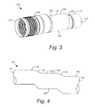
- Fig. 3 shows a combustor liner 200 as may be described herein.
- the combustion liner 200 may be a unified element.
- the combustor liner 200 may include a mouth 205, a combustion zone 210, a number of angled transition zones 220, at least one straight transition zone 230, and an off center throat 240 with an off center exit 245.
- the combustor liner 200 has an essentially flat first side 250 and with the angle transitions zones 220 positioned about a stepped second side 260.
- the flow path through the liner 200 is off center as compared to the entrance of the mouth 205.
- the flow path takes a small dip in each of the angled transition zones 220, the flow path is actually less restrictive therethrough. Any number of angled transition zones 220 may be used.
- the off center throat 240 and the exit 245 of the liner 200 thus provides a shape similar to that of a Forstman funnel concept.
- a Forstman funnel is a funnel with the exit mouth being off center from the inlet. Liquid flowing through a funnel tends to swirl and form a whirlpool. As a result, centrifugal forces move the liquid away from the drain hole thus reducing the funnel capacity.
- the asymmetric shape of the Forstman funnel reduces the rotation speed of the liquid in the whirlpool such that the funnel capacity may be increased. Such a design may flow about fifty percent (50%) to about seventy percent (70%) more than a conventional funnel.
- the design provides a more stable flow exiting the combustor 100 as compared to conventional cylindrically shaped components. Increased flow through the combustor 100 thus may allow for more complete airflow mixing. Likewise, the combustion zone 210 is lengthened by eliminating the curved transition piece 190. Improved mixing thus should result. More uniform flow and better mixing also should promote more complete combustion and hence lower emissions. Likewise, more even exhaust temperatures should result.
- the design should increase flow, cooling, and/or the exhaust profile by making the flow path therethrough less restrictive.
- Fig. 4 shows an alternative embodiment of a combustor liner 300 as is described herein.
- the combustor liner 300 includes a mouth 305, a combustion zone 310, a number of angled transition zones 320, one or more straight transition zones 330, and an off center throat 340 with an off center exit 345.
- the combustor liner 300 instead of the flat first side 250, the combustor liner 300 includes a stepped first side 350 that matches a stepped second side 360. As a result, the flow path therethrough is even more off center as compared to the combustor liner 200 described above.
- Forstman funnel concept described herein has focused on the combustor liners 200, 300, the concept also could be applied to flow sleeves, combustion cases, liner cap assemblies, secondary and primary fuel nozzles, fuel nozzle tips, end cover primary fuel nozzles, and in any place that flow goes through a staggered hole or is necked down.
Landscapes
- Engineering & Computer Science (AREA)
- Chemical & Material Sciences (AREA)
- Combustion & Propulsion (AREA)
- Mechanical Engineering (AREA)
- General Engineering & Computer Science (AREA)
Abstract
The present application provides a liner (200) for a combustor (100). The combustor liner (200) may include a mouth (205), one or more angled transition zones (220), and an off center exit (245).
Description
- The present application relates generally to gas turbine engines and more particularly relates to a combustor liner or other type of passage with an off center throat and exit.
- Modern gas turbine engines generally must operate under strict emissions guidelines, particularly with respect to nitrogen oxides (NOx). As such, gas turbine engine design must operate at high efficiency without producing undesirable air emissions. Many modem gas turbine engines thus use a very lean, premixed flame for low NOx combustion.
- One way to limit turbine emissions is to ensure good mixing of the fuel and the air in the combustor. Proper mixing may involve mixing flow manipulation using dilution tuning or similar methods. Tuning a combustor in the field, however, may be difficult and time consuming. Moreover, the need to tune properly a combustor also may influence the time required for initial commissioning and/or cause other types of delays.
- There is thus a desire for an improved combustor and other types of turbine components that promote good mixing of both fuel and air while providing high overall efficiency with limited emissions. Preferably the combustor or the other components may be used with new and existing equipment.
- The present application thus provides for a liner for a combustor. The combustor liner may include a mouth, one or more angled transition zones, and an off center exit.
- The present application also provides for a method of mixing fuel and air in a combustor. The method may include the steps of flowing the fuel and the air into a combustor liner, flowing the fuel and the air through one or more angled transition zones, and flowing the fuel and the air through an off center throat.
- The present application also provides for a gas turbine. The gas turbine may include a passage for a flow of fuel, a passage for a flow of air, a first zone for mixing the flow of fuel and the flow of air, one or more angled transition zones down stream of the first zone, and an off center exit down stream of the one or more angled transition zones.
- There follows a detailed description of embodiments of the invention by way of example only with reference to the accompanying drawings, in which:
-
Fig. 1 is a schematic view of a gas turbine engine; -
Fig. 2 is a side cross-section view of a combustor that may be used with the gas turbine engine ofFig. 1 ; -
Fig. 3 is a perspective view of a combustor liner as may be described herein; and -
Fig. 4 is a perspective view of an alternative combustor liner as may be described herein. - Referring now to the drawings, in which like numbers refer to like elements throughout the several views,
Fig. 1 shows a schematic view of agas turbine engine 10. As is known, thegas turbine engine 10 may include acompressor 20 to compress an incoming flow of air. Thecompressor 20 delivers the compressed flow of air to thecombustor 30. Thecombustor 30 mixes the compressed flow of air with a flow of fuel and ignites the mixture. The hot combustion gases are in turn delivered to aturbine 40. Theturbine 40 drives thecompressor 20 and anexternal load 50 such as an electrical generator and the like. Thegas turbine engine 10 may use other configurations and components herein. -
Fig. 2 shows an example of acombustor 100 as may be used herein. In this example, thecombustor 100 may be a Model 6B or Model 7EA of the DLN-1 (Dry Low NOx) Combustor System offered by General Electric Company of Schenectady, New York. - The concepts described herein, however, may be applicable to any type of combustor and also to many other types of turbine related components and other types of pathways.
- Generally described, the
combustor 100 may include anend cover assembly 110. Theend cover assembly 110 may include a number offuel manifolds 120. Thefuel manifolds 120 may be in communication with afuel nozzle assembly 130. Thefuel nozzle assembly 130 may support both diffusion and premixed combustion. Compressed air may be delivered to thecombustor 100 by thecompressor 20 via anair passage 140. Theair passage 140 may be defined by acombustor flow sleeve 150 and acombustor liner 160. Many other designs and turbine configurations also may be used herein. - The fuel flows and the air flows may meet about the
fuel nozzle assembly 130 and may be ignited within thecombustion liner 160. Thecombustor liner 160 may include amixing zone 170 and acombustion zone 180. Thecombustor liner 160 extends into atransition piece 190 that is adjacent to theturbine 40. As is shown, the existingcombustor liner designs 160 are essentially concentric in shape with a horizontal centerline extending uniformly therethrough. At least a portion of the flow path, however, comes into contact with thecurved transition piece 190. This concentric shape of theliner 160, when combined with the curve of thetransition piece 190, thus may create a somewhat restrictive flow path therethrough. -
Fig. 3 shows acombustor liner 200 as may be described herein. Instead of thecombustion liner 160 with themixing zone 170 and thecombustion zone 180 merging into thetransition piece 190 as is described above, thecombustion liner 200 may be a unified element. Thecombustor liner 200 may include amouth 205, acombustion zone 210, a number ofangled transition zones 220, at least onestraight transition zone 230, and an offcenter throat 240 with an offcenter exit 245. As is shown, thecombustor liner 200 has an essentially flatfirst side 250 and with theangle transitions zones 220 positioned about a steppedsecond side 260. As a result of this shape, the flow path through theliner 200 is off center as compared to the entrance of themouth 205. Although the flow path takes a small dip in each of theangled transition zones 220, the flow path is actually less restrictive therethrough. Any number ofangled transition zones 220 may be used. - The off
center throat 240 and theexit 245 of theliner 200 thus provides a shape similar to that of a Forstman funnel concept. A Forstman funnel is a funnel with the exit mouth being off center from the inlet. Liquid flowing through a funnel tends to swirl and form a whirlpool. As a result, centrifugal forces move the liquid away from the drain hole thus reducing the funnel capacity. The asymmetric shape of the Forstman funnel, however, reduces the rotation speed of the liquid in the whirlpool such that the funnel capacity may be increased. Such a design may flow about fifty percent (50%) to about seventy percent (70%) more than a conventional funnel. - Applying this concept to a
combustor 100, the design provides a more stable flow exiting thecombustor 100 as compared to conventional cylindrically shaped components. Increased flow through thecombustor 100 thus may allow for more complete airflow mixing. Likewise, thecombustion zone 210 is lengthened by eliminating thecurved transition piece 190. Improved mixing thus should result. More uniform flow and better mixing also should promote more complete combustion and hence lower emissions. Likewise, more even exhaust temperatures should result. The design should increase flow, cooling, and/or the exhaust profile by making the flow path therethrough less restrictive. -
Fig. 4 shows an alternative embodiment of acombustor liner 300 as is described herein. As described above, thecombustor liner 300 includes amouth 305, acombustion zone 310, a number ofangled transition zones 320, one or morestraight transition zones 330, and anoff center throat 340 with anoff center exit 345. In this embodiment, however, instead of the flatfirst side 250, thecombustor liner 300 includes a steppedfirst side 350 that matches a steppedsecond side 360. As a result, the flow path therethrough is even more off center as compared to thecombustor liner 200 described above. - Although the Forstman funnel concept described herein has focused on the
combustor liners - It should be apparent that the foregoing relates only to the preferred embodiments of the present application and that numerous changes and modifications may be made herein by one of ordinary skill in the art without departing from the general spirit and scope of the invention as defined by the following claims and the equivalents thereof.
Claims (15)
- A liner (200) for a combustor (100), comprising:a mouth (205);one or more angled transition zones (220); andan off center exit (245).
- The liner (200) of claim 1, further comprising a combustion zone (210).
- The liner (200) of claim 1 or 2, further comprising one or more straight transition zones (230).
- The liner (200) of any of the preceding claims, further comprising an off center throat (240) positioned about the off center exit (245).
- The liner (200) of claim 4, wherein the off center exit (245) and the off center throat (240) comprise a Forstman funnel.
- The liner (200) of any of the preceding claims, wherein the one or more angled transition zones (220) comprise a first flat side (250) and a second stepped side (260).
- The liner (200) of any of claims 1 to 5, wherein the one or more angled transition zones (220) comprise a first stepped side (350) and a second stepped side (360).
- A method of mixing fuel and air in a combustor (100), comprising:flowing the fuel and the air into a combustor liner (200);flowing the fuel and the air through one or more angled transition zones (220); andflowing the fuel and the air through an off center throat (240).
- The method of claim 8, wherein the steps of flowing the fuel and the air through one or more angled transition zones (220) and through an off center throat (240) comprises reducing a rotational speed of the flow of the fuel and the air as they flow therethrough.
- A gas turbine, comprising:a passage for a flow of fuel;a passage for a flow of air;a first zone for mixing the flow of fuel and the flow of air;one or more angled transition zones down stream of the first zone; andan off center exit down stream of the one or more angled transition zones.
- The gas turbine of claim 10, wherein the first zone comprises a combustion zone.
- The gas turbine of claim 10 or 11, further comprising one or more straight transition zones.
- The gas turbine of any of claims 10 to 12, further comprising an off center throat positioned about the off center exit.
- The gas turbine of claim 13, wherein the off center exit and the off center throat comprise a Forstman funnel.
- The gas turbine of any of claims 10 to 14, wherein the one or more angled transition zones comprise a first flat side and a second stepped side.
Applications Claiming Priority (1)
| Application Number | Priority Date | Filing Date | Title |
|---|---|---|---|
| US12/243,122 US8056343B2 (en) | 2008-10-01 | 2008-10-01 | Off center combustor liner |
Publications (1)
| Publication Number | Publication Date |
|---|---|
| EP2172707A2 true EP2172707A2 (en) | 2010-04-07 |
Family
ID=41463081
Family Applications (1)
| Application Number | Title | Priority Date | Filing Date |
|---|---|---|---|
| EP09171719A Withdrawn EP2172707A2 (en) | 2008-10-01 | 2009-09-30 | Off center combustor liner |
Country Status (4)
| Country | Link |
|---|---|
| US (1) | US8056343B2 (en) |
| EP (1) | EP2172707A2 (en) |
| JP (1) | JP2010085088A (en) |
| CN (1) | CN101713540A (en) |
Families Citing this family (5)
| Publication number | Priority date | Publication date | Assignee | Title |
|---|---|---|---|---|
| US8020385B2 (en) * | 2008-07-28 | 2011-09-20 | General Electric Company | Centerbody cap for a turbomachine combustor and method |
| US8028529B2 (en) * | 2006-05-04 | 2011-10-04 | General Electric Company | Low emissions gas turbine combustor |
| US20120208141A1 (en) * | 2011-02-14 | 2012-08-16 | General Electric Company | Combustor |
| US8915706B2 (en) | 2011-10-18 | 2014-12-23 | General Electric Company | Transition nozzle |
| CN105754623B (en) * | 2016-03-21 | 2018-11-06 | 陈明海 | A kind of off-gas recovery utilizes low NOx biomass carbonizing furnaces |
Family Cites Families (59)
| Publication number | Priority date | Publication date | Assignee | Title |
|---|---|---|---|---|
| US3596813A (en) * | 1968-06-21 | 1971-08-03 | Elvin R Munn | Paint bucket lid with pouring spout |
| US3608309A (en) * | 1970-05-21 | 1971-09-28 | Gen Electric | Low smoke combustion system |
| US3845791A (en) * | 1970-10-15 | 1974-11-05 | Continental Can Co | Universal filling head |
| US3807464A (en) * | 1972-11-06 | 1974-04-30 | I Pitesky | Power operated syringe holding device for filtering a liquid |
| US4179881A (en) * | 1973-02-28 | 1979-12-25 | United Technologies Corporation | Premix combustor assembly |
| US4271674A (en) * | 1974-10-17 | 1981-06-09 | United Technologies Corporation | Premix combustor assembly |
| US4845940A (en) * | 1981-02-27 | 1989-07-11 | Westinghouse Electric Corp. | Low NOx rich-lean combustor especially useful in gas turbines |
| US4600125A (en) * | 1983-08-15 | 1986-07-15 | Maynard Jr Walter P | Liquid funnel and pouring spout combination |
| US4653278A (en) * | 1985-08-23 | 1987-03-31 | General Electric Company | Gas turbine engine carburetor |
| CA1228555A (en) * | 1987-03-09 | 1987-10-27 | Walter A. Matthews | Container for liquids |
| US4875339A (en) | 1987-11-27 | 1989-10-24 | General Electric Company | Combustion chamber liner insert |
| JP2928607B2 (en) * | 1989-12-22 | 1999-08-03 | 株式会社日立製作所 | Combustion apparatus and combustion method thereof |
| CA2048726A1 (en) | 1990-11-15 | 1992-05-16 | Phillip D. Napoli | Combustor liner with circumferentially angled film cooling holes |
| CA2056592A1 (en) | 1990-12-21 | 1992-06-22 | Phillip D. Napoli | Multi-hole film cooled combustor liner with slotted film starter |
| US5165226A (en) * | 1991-08-09 | 1992-11-24 | Pratt & Whitney Canada, Inc. | Single vortex combustor arrangement |
| US5253478A (en) | 1991-12-30 | 1993-10-19 | General Electric Company | Flame holding diverging centerbody cup construction for a dry low NOx combustor |
| US5211308A (en) * | 1992-02-27 | 1993-05-18 | Nyco International, Inc. | Universal funnel for a paper dispenser |
| US5329759A (en) * | 1993-06-30 | 1994-07-19 | Pratt & Whitney Canada, Inc. | Method for regulating fuel flow in a gas turbine engine |
| US5465570A (en) * | 1993-12-22 | 1995-11-14 | United Technologies Corporation | Fuel control system for a staged combustor |
| US5891207A (en) * | 1994-01-06 | 1999-04-06 | Hks Co., Ltd. | Engine intake-air filter apparatus |
| JPH10506150A (en) * | 1994-08-01 | 1998-06-16 | フランツ ヘーマン、 | Processes selected for non-equilibrium lightweight alloys and products |
| US5649992A (en) * | 1995-10-02 | 1997-07-22 | General Electric Company | Methods for flow control in electroslag refining process |
| SE505498C2 (en) * | 1996-07-09 | 1997-09-08 | Kvaerner Pulping Tech | The chip pocket |
| DE19647947A1 (en) * | 1996-11-20 | 1998-05-28 | Pfeiffer Erich Gmbh & Co Kg | Discharge device for media |
| US6006523A (en) * | 1997-04-30 | 1999-12-28 | Mitsubishi Heavy Industries, Ltd. | Gas turbine combustor with angled tube section |
| US6070753A (en) * | 1998-02-02 | 2000-06-06 | Exxon Research And Engineering Co. | Liquid container |
| US6311471B1 (en) * | 1999-01-08 | 2001-11-06 | General Electric Company | Steam cooled fuel injector for gas turbine |
| GB9917957D0 (en) * | 1999-07-31 | 1999-09-29 | Rolls Royce Plc | A combustor arrangement |
| US6250063B1 (en) * | 1999-08-19 | 2001-06-26 | General Electric Co. | Fuel staging apparatus and methods for gas turbine nozzles |
| US6279313B1 (en) * | 1999-12-14 | 2001-08-28 | General Electric Company | Combustion liner for gas turbine having liner stops |
| US6484505B1 (en) * | 2000-02-25 | 2002-11-26 | General Electric Company | Combustor liner cooling thimbles and related method |
| US6497105B1 (en) * | 2001-06-04 | 2002-12-24 | Pratt & Whitney Canada Corp. | Low cost combustor burner collar |
| DE60237895D1 (en) * | 2001-06-12 | 2010-11-18 | S & S Concepts Inc | FOLDABLE MULTIPURPOSE HUNTER |
| US6651437B2 (en) * | 2001-12-21 | 2003-11-25 | General Electric Company | Combustor liner and method for making thereof |
| US7086232B2 (en) * | 2002-04-29 | 2006-08-08 | General Electric Company | Multihole patch for combustor liner of a gas turbine engine |
| US6725667B2 (en) * | 2002-08-22 | 2004-04-27 | General Electric Company | Combustor dome for gas turbine engine |
| US6983606B2 (en) * | 2002-09-09 | 2006-01-10 | Florida Turbine Technologies, Inc. | Integrated gas turbine compressor-rotary fuel injector |
| EP1620203A2 (en) * | 2003-04-10 | 2006-02-01 | U.S. Genomics, Inc. | Manipulation of polymers in a microchannel |
| US6986253B2 (en) * | 2003-07-16 | 2006-01-17 | General Electric Company | Methods and apparatus for cooling gas turbine engine combustors |
| US6996990B2 (en) * | 2003-08-27 | 2006-02-14 | General Electric Company | Flow controller for gas turbine combustors |
| JP2005076982A (en) * | 2003-08-29 | 2005-03-24 | Mitsubishi Heavy Ind Ltd | Gas turbine combustor |
| US7284378B2 (en) * | 2004-06-04 | 2007-10-23 | General Electric Company | Methods and apparatus for low emission gas turbine energy generation |
| US20050056313A1 (en) * | 2003-09-12 | 2005-03-17 | Hagen David L. | Method and apparatus for mixing fluids |
| JP3944609B2 (en) * | 2003-12-16 | 2007-07-11 | 川崎重工業株式会社 | Fuel nozzle |
| US6951109B2 (en) * | 2004-01-06 | 2005-10-04 | General Electric Company | Apparatus and methods for minimizing and/or eliminating dilution air leakage in a combustion liner assembly |
| US7185497B2 (en) * | 2004-05-04 | 2007-03-06 | Honeywell International, Inc. | Rich quick mix combustion system |
| US7017628B2 (en) * | 2004-05-25 | 2006-03-28 | California Pacific Lab, Inc. | Ecologically friendly funnel |
| US7010921B2 (en) * | 2004-06-01 | 2006-03-14 | General Electric Company | Method and apparatus for cooling combustor liner and transition piece of a gas turbine |
| US7146816B2 (en) * | 2004-08-16 | 2006-12-12 | Honeywell International, Inc. | Effusion momentum control |
| US7373778B2 (en) * | 2004-08-26 | 2008-05-20 | General Electric Company | Combustor cooling with angled segmented surfaces |
| US7546735B2 (en) * | 2004-10-14 | 2009-06-16 | General Electric Company | Low-cost dual-fuel combustor and related method |
| US20060096909A1 (en) * | 2004-11-09 | 2006-05-11 | Roger Patch | Conductive plastic fuel filter funnel having improved flow rate and separation |
| US7475741B2 (en) * | 2004-11-30 | 2009-01-13 | General Electric Company | Method and system for precise drilling guidance of twin wells |
| US20060191268A1 (en) * | 2005-02-25 | 2006-08-31 | General Electric Company | Method and apparatus for cooling gas turbine fuel nozzles |
| US7513100B2 (en) * | 2005-10-24 | 2009-04-07 | General Electric Company | Systems for low emission gas turbine energy generation |
| US7665307B2 (en) * | 2005-12-22 | 2010-02-23 | United Technologies Corporation | Dual wall combustor liner |
| US7966823B2 (en) * | 2006-01-06 | 2011-06-28 | General Electric Company | Exhaust dust flow splitter system |
| US7571611B2 (en) * | 2006-04-24 | 2009-08-11 | General Electric Company | Methods and system for reducing pressure losses in gas turbine engines |
| US8156743B2 (en) | 2006-05-04 | 2012-04-17 | General Electric Company | Method and arrangement for expanding a primary and secondary flame in a combustor |
-
2008
- 2008-10-01 US US12/243,122 patent/US8056343B2/en not_active Expired - Fee Related
-
2009
- 2009-09-30 JP JP2009225685A patent/JP2010085088A/en not_active Withdrawn
- 2009-09-30 EP EP09171719A patent/EP2172707A2/en not_active Withdrawn
- 2009-09-30 CN CN200910205208A patent/CN101713540A/en active Pending
Also Published As
| Publication number | Publication date |
|---|---|
| US8056343B2 (en) | 2011-11-15 |
| US20100077762A1 (en) | 2010-04-01 |
| JP2010085088A (en) | 2010-04-15 |
| CN101713540A (en) | 2010-05-26 |
Similar Documents
| Publication | Publication Date | Title |
|---|---|---|
| US7966822B2 (en) | Reverse-flow gas turbine combustion system | |
| US6354072B1 (en) | Methods and apparatus for decreasing combustor emissions | |
| US6871501B2 (en) | Method and apparatus to decrease gas turbine engine combustor emissions | |
| EP1167881B1 (en) | Methods and apparatus for decreasing combustor emissions with swirl stabilized mixer | |
| US7716931B2 (en) | Method and apparatus for assembling gas turbine engine | |
| US8381532B2 (en) | Bled diffuser fed secondary combustion system for gas turbines | |
| CN102444911B (en) | There is the burner of poor pre-spraying nozzle fuel injection system | |
| US8113002B2 (en) | Combustor burner vanelets | |
| CN102022728B (en) | For the radial inlet guide vanes of burner | |
| EP2366952A2 (en) | Combustor with pre-mixing primary fuel-nozzle assembly | |
| US6862889B2 (en) | Method and apparatus to decrease combustor emissions | |
| EP1333228A3 (en) | Method and apparatus to decrease combustor emissions | |
| US20100018181A1 (en) | Centerbody cap for a turbomachine combustor and method | |
| US8056343B2 (en) | Off center combustor liner | |
| US7059135B2 (en) | Method to decrease combustor emissions | |
| JP2011140952A (en) | Fuel nozzle for turbine engine with passive purge air passageway | |
| CN102721084B (en) | Burner flame tube interconnector | |
| JP2013148339A (en) | Combustor nozzle/premixer with curved section | |
| CN103423773A (en) | Secondary combustion system | |
| CN103363524A (en) | Diffusion combustor fuel nozzle | |
| CN102679400B (en) | There is the burner of prenozzle mixing cap assembly | |
| EP2503243A1 (en) | Combustor with fuel nozzle liner having chevron ribs | |
| EP1835231A1 (en) | Burner in particular for a gas turbine combustor, and method of operating a burner | |
| US20140150452A1 (en) | Transition piece for a gas turbine system | |
| IL142606A (en) | Methods and apparatus for decreasing combustor emissions with swirl stabilized mixer |
Legal Events
| Date | Code | Title | Description |
|---|---|---|---|
| PUAI | Public reference made under article 153(3) epc to a published international application that has entered the european phase |
Free format text: ORIGINAL CODE: 0009012 |
|
| AK | Designated contracting states |
Kind code of ref document: A2 Designated state(s): AT BE BG CH CY CZ DE DK EE ES FI FR GB GR HR HU IE IS IT LI LT LU LV MC MK MT NL NO PL PT RO SE SI SK SM TR |
|
| AX | Request for extension of the european patent |
Extension state: AL BA RS |
|
| STAA | Information on the status of an ep patent application or granted ep patent |
Free format text: STATUS: THE APPLICATION IS DEEMED TO BE WITHDRAWN |
|
| 18D | Application deemed to be withdrawn |
Effective date: 20140401 |