EP2172677A1 - Method for controlling the upshift operation in a motor vehicle equipped with a double clutch transmission - Google Patents
Method for controlling the upshift operation in a motor vehicle equipped with a double clutch transmission Download PDFInfo
- Publication number
- EP2172677A1 EP2172677A1 EP08425642A EP08425642A EP2172677A1 EP 2172677 A1 EP2172677 A1 EP 2172677A1 EP 08425642 A EP08425642 A EP 08425642A EP 08425642 A EP08425642 A EP 08425642A EP 2172677 A1 EP2172677 A1 EP 2172677A1
- Authority
- EP
- European Patent Office
- Prior art keywords
- dis
- value
- friction clutch
- torque
- inn
- Prior art date
- Legal status (The legal status is an assumption and is not a legal conclusion. Google has not performed a legal analysis and makes no representation as to the accuracy of the status listed.)
- Granted
Links
Images


Classifications
-
- F—MECHANICAL ENGINEERING; LIGHTING; HEATING; WEAPONS; BLASTING
- F16—ENGINEERING ELEMENTS AND UNITS; GENERAL MEASURES FOR PRODUCING AND MAINTAINING EFFECTIVE FUNCTIONING OF MACHINES OR INSTALLATIONS; THERMAL INSULATION IN GENERAL
- F16H—GEARING
- F16H61/00—Control functions within control units of change-speed- or reversing-gearings for conveying rotary motion ; Control of exclusively fluid gearing, friction gearing, gearings with endless flexible members or other particular types of gearing
- F16H61/68—Control functions within control units of change-speed- or reversing-gearings for conveying rotary motion ; Control of exclusively fluid gearing, friction gearing, gearings with endless flexible members or other particular types of gearing specially adapted for stepped gearings
- F16H61/684—Control functions within control units of change-speed- or reversing-gearings for conveying rotary motion ; Control of exclusively fluid gearing, friction gearing, gearings with endless flexible members or other particular types of gearing specially adapted for stepped gearings without interruption of drive
- F16H61/688—Control functions within control units of change-speed- or reversing-gearings for conveying rotary motion ; Control of exclusively fluid gearing, friction gearing, gearings with endless flexible members or other particular types of gearing specially adapted for stepped gearings without interruption of drive with two inputs, e.g. selection of one of two torque-flow paths by clutches
-
- B—PERFORMING OPERATIONS; TRANSPORTING
- B60—VEHICLES IN GENERAL
- B60W—CONJOINT CONTROL OF VEHICLE SUB-UNITS OF DIFFERENT TYPE OR DIFFERENT FUNCTION; CONTROL SYSTEMS SPECIALLY ADAPTED FOR HYBRID VEHICLES; ROAD VEHICLE DRIVE CONTROL SYSTEMS FOR PURPOSES NOT RELATED TO THE CONTROL OF A PARTICULAR SUB-UNIT
- B60W10/00—Conjoint control of vehicle sub-units of different type or different function
- B60W10/04—Conjoint control of vehicle sub-units of different type or different function including control of propulsion units
- B60W10/06—Conjoint control of vehicle sub-units of different type or different function including control of propulsion units including control of combustion engines
-
- B—PERFORMING OPERATIONS; TRANSPORTING
- B60—VEHICLES IN GENERAL
- B60W—CONJOINT CONTROL OF VEHICLE SUB-UNITS OF DIFFERENT TYPE OR DIFFERENT FUNCTION; CONTROL SYSTEMS SPECIALLY ADAPTED FOR HYBRID VEHICLES; ROAD VEHICLE DRIVE CONTROL SYSTEMS FOR PURPOSES NOT RELATED TO THE CONTROL OF A PARTICULAR SUB-UNIT
- B60W10/00—Conjoint control of vehicle sub-units of different type or different function
- B60W10/10—Conjoint control of vehicle sub-units of different type or different function including control of change-speed gearings
- B60W10/11—Stepped gearings
- B60W10/113—Stepped gearings with two input flow paths, e.g. double clutch transmission selection of one of the torque flow paths by the corresponding input clutch
-
- B—PERFORMING OPERATIONS; TRANSPORTING
- B60—VEHICLES IN GENERAL
- B60W—CONJOINT CONTROL OF VEHICLE SUB-UNITS OF DIFFERENT TYPE OR DIFFERENT FUNCTION; CONTROL SYSTEMS SPECIALLY ADAPTED FOR HYBRID VEHICLES; ROAD VEHICLE DRIVE CONTROL SYSTEMS FOR PURPOSES NOT RELATED TO THE CONTROL OF A PARTICULAR SUB-UNIT
- B60W30/00—Purposes of road vehicle drive control systems not related to the control of a particular sub-unit, e.g. of systems using conjoint control of vehicle sub-units
- B60W30/18—Propelling the vehicle
- B60W30/19—Improvement of gear change, e.g. by synchronisation or smoothing gear shift
-
- F—MECHANICAL ENGINEERING; LIGHTING; HEATING; WEAPONS; BLASTING
- F16—ENGINEERING ELEMENTS AND UNITS; GENERAL MEASURES FOR PRODUCING AND MAINTAINING EFFECTIVE FUNCTIONING OF MACHINES OR INSTALLATIONS; THERMAL INSULATION IN GENERAL
- F16H—GEARING
- F16H61/00—Control functions within control units of change-speed- or reversing-gearings for conveying rotary motion ; Control of exclusively fluid gearing, friction gearing, gearings with endless flexible members or other particular types of gearing
- F16H61/04—Smoothing ratio shift
- F16H61/0437—Smoothing ratio shift by using electrical signals
-
- B—PERFORMING OPERATIONS; TRANSPORTING
- B60—VEHICLES IN GENERAL
- B60W—CONJOINT CONTROL OF VEHICLE SUB-UNITS OF DIFFERENT TYPE OR DIFFERENT FUNCTION; CONTROL SYSTEMS SPECIALLY ADAPTED FOR HYBRID VEHICLES; ROAD VEHICLE DRIVE CONTROL SYSTEMS FOR PURPOSES NOT RELATED TO THE CONTROL OF A PARTICULAR SUB-UNIT
- B60W2710/00—Output or target parameters relating to a particular sub-units
- B60W2710/06—Combustion engines, Gas turbines
- B60W2710/0666—Engine torque
Definitions
- the present invention relates to a method for controlling the operation of changing to a higher gear (upshift) in a motor vehicle equipped with a double clutch transmission.
- a typical double clutch transmission for a motor vehicle is generally indicated 10 and comprises a first primary shaft 12 carrying a plurality of driving gearwheels (only one of which is schematically shown and is indicated 14) associated with a first set of gears (for example the odd gears), a second primary shaft 16 carrying a plurality of driving gearwheels (only one of which is schematically shown and is indicated 18) associated with the remaining gears (for example the even gears), a first friction clutch 20 designed to couple the first primary shaft 12 for rotation with a driving shaft 22 of the vehicle, a second friction clutch 24 designed to couple the second primary shaft 16 for rotation with the driving shaft 22, and one or more secondary shafts (in the example shown a first secondary shaft 26 and a second secondary shaft 28) carrying a plurality of driven gearwheels (of which only a first driven gearwheel 30 is shown schematically, said gearwheel being carried by the first secondary shaft 26 and meshing permanently with the driving gearwheel 14, together with a second driven gearwheel 32, which is carried by the second
- the transmission of the torque may therefore take place both via a first section of the transmission consisting of the first friction clutch 20, the first primary shaft 12 and the first secondary shaft 26, and via a second section of the transmission consisting of the second friction clutch 24, the second primary shaft 16 and the second secondary shaft 28.
- the gear changing operation is performed in so-called powershift mode, namely with a phase where the starting gears (disengaging gear) and the end gears (engaging gear), which are each associated with a respective section of the transmission, are simultaneously engaged and transmission of the torque occurs via both sections of the transmission.
- Transfer of the torque from the disengaging section to the engaging section of the transmission therefore occurs by means of opening of the friction clutch associated with the disengaging gear and simultaneous closing of the friction clutch associated with the engaging gear.
- This phase is referred to hereinbelow as the crossover phase of the friction clutches or quite simply as the crossover phase. Opening of a clutch and simultaneous closing of the other clutch must be modulated according to suitable control logics which aim to ensure that the gear changing operation is performed as rapidly and comfortably as possible.
- the crossover phase of the friction clutches is preceded by a phase where the transmission of the driving power from the engine to the wheels occurs via a single section of the transmission, namely the section associated with the disengaging gear, the first friction clutch 20 (disengaging gear) being closed and the second friction clutch 24 (engaging gear) being open.
- the gear changing operation provides firstly for engagement of the engaging gear, obtained by means of rotational coupling between the idle gearwheel (which may be equally well the driving gearwheel or the driven gearwheel) of the gearing associated with this gear and the respective shaft (primary or secondary shaft, respectively), typically by means of a sliding engaging sleeve, while the friction clutch associated with the engaging gear is kept open, then the crossover phase of the friction clutches, during which the friction clutch associated with the disengaging gear is gradually opened, while the friction clutch associated with the engaging gear is gradually closed, and finally disengagement of the disengaging gear by means of uncoupling of the idle gearwheel (driving or driven gearwheel) of the gearing associated with this gear from the respective shaft (primary or secondary shaft, respectively).
- a first constraint imposed in the known strategies for controlling the gear changing operation is the synchronism between the angular velocities ⁇ m of the driving shaft 22 and ⁇ p,dis of the first primary shaft 12 (disengaging gear).
- the previous transmission model with both the friction clutches 20 and 24 in a slipping condition defined by the equations (3) and (4), is replaced by a new transmission model in which only the second friction clutch 24 is in a slipping condition, while the first friction clutch 20 is closed and therefore the first primary shaft 12 (disengaging gear) rotates at the same angular velocity as the driving shaft 22.
- the equation (15) represents a general constraint for selection of the torque profile of the first friction clutch (clutch to be opened) which ensures no slipping of this clutch
- the equation (17) represents the link between the final values of the engine torque and of the torque of the second friction clutch (clutch to be closed) which ensures the synchronism between the angular velocities of the driving shaft and of the first primary shaft (disengaging gear) and the continuity of the angular acceleration at the time of opening of the first friction clutch.
- the object of the present invention is to provide a method for controlling the operation of changing to a higher gear (upshift) in a motor vehicle equipped with a double clutch transmission, which enables to control the loss of longitudinal acceleration of the vehicle during the crossover phase of the friction clutches in a gear changing operation, in particular in an upshift operation.
- This preferred mode of implementation of the control method is based on the idea of determining a given profile for the longitudinal acceleration of the vehicle during the crossover phase and defining consequently the profile of the engine torque. If, for example, a constant profile is determined for the longitudinal acceleration of the vehicle, the engine torque is incremented accordingly during the crossover phase.
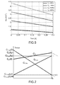
- Figure 2 of the accompanying drawings shows the time course, during the crossover phase, of the torques of the engine and of the two friction clutches according to the preferred mode of implementation of the present invention described above, and more particularly according to a control strategy which envisages determining a constant profile for the longitudinal acceleration of the vehicle during the crossover phase.
- the driving torque is incremented during the crossover phase to such an extent as to obtain a substantially constant profile for the longitudinal acceleration of the vehicle.
- C ⁇ m C m t fi - C m 0 t fi ;
- C ⁇ F , inn C F , inn t fi t fi .
- Figure 3 of the accompanying drawings shows examples of engine torque profiles, with the corresponding final values of the torque of the friction clutch to be closed, which satisfy the condition of constant longitudinal acceleration during the crossover phase when changing from 1st to 2nd gear.
- the control method may also be implemented allowing for a certain reduction in the longitudinal acceleration of the vehicle during the crossover phase and therefore determining a final value for the longitudinal acceleration which is equal to a given percentage of the initial value.
- step d) If the final value of the engine torque calculated in step d) is greater than the maximum value which the engine is able to provide, then the final value of the engine torque is suitably limited and the final value C F , inn ( t fi ) of the torque of the friction clutch to be closed is calculated by inversion of the equation (17) using the set value C m ( t f i ).
- C F,inn ( t fi ) the minimum between the value calculated in step b) (value corresponding to the zero jerk condition) and the torque value at the end of the phase where torque is supplied again to the engine after the crossover phase, so as to minimize the reduction in the acceleration during the period after crossover of the friction clutches.
- the torque profiles during the crossover phase are determined according to the following steps:
- Figure 4 of the accompanying drawings shows two graphs which illustrate the time course of the torques and of the angular velocities in a double clutch transmission for a motor vehicle during the crossover phase of the friction clutches according to the alternative mode of implementation of the control method described above.
- the reduction in the engine torque is preferably anticipated with respect to the final time t fi of the crossover phase, i.e. the engine torque C m is kept constant until the time t fi - ⁇ t m and then decreased (for example linearly) until the time t fi .
- Control of the gear changing operation according to the invention may be performed in an open loop, even though closed loop control is preferable in view of the greater robustness.
- the invention is applicable not only to twowheel drive vehicles but also to four-wheel drive vehicles, not only to road vehicles but also to off-road vehicles, not only to vehicles with a transverse gearbox but also to vehicles with a longitudinal gearbox and not only to vehicles with synchronizers mounted on the two primary shafts of the gearbox but also to vehicles with synchronizers mounted on the secondary shaft (or secondary shafts) of the gearbox.
- the invention is applicable not only to vehicles with double clutch transmissions, but also to vehicles equipped with a transmission which has more than two friction clutches (for example tractors and industrial vehicles).
Landscapes
- Engineering & Computer Science (AREA)
- Mechanical Engineering (AREA)
- General Engineering & Computer Science (AREA)
- Chemical & Material Sciences (AREA)
- Combustion & Propulsion (AREA)
- Transportation (AREA)
- Automation & Control Theory (AREA)
- Control Of Transmission Device (AREA)
Abstract
Description
- The present invention relates to a method for controlling the operation of changing to a higher gear (upshift) in a motor vehicle equipped with a double clutch transmission.
- With reference to
Figure 1 of the accompanying drawings, a typical double clutch transmission for a motor vehicle is generally indicated 10 and comprises a first primary shaft 12 carrying a plurality of driving gearwheels (only one of which is schematically shown and is indicated 14) associated with a first set of gears (for example the odd gears), a second primary shaft 16 carrying a plurality of driving gearwheels (only one of which is schematically shown and is indicated 18) associated with the remaining gears (for example the even gears), a first friction clutch 20 designed to couple the first primary shaft 12 for rotation with a driving shaft 22 of the vehicle, a second friction clutch 24 designed to couple the second primary shaft 16 for rotation with the driving shaft 22, and one or more secondary shafts (in the example shown a first secondary shaft 26 and a second secondary shaft 28) carrying a plurality of driven gearwheels (of which only a first driven gearwheel 30 is shown schematically, said gearwheel being carried by the first secondary shaft 26 and meshing permanently with the driving gearwheel 14, together with a second driven gearwheel 32, which is carried by the second secondary shaft 28 and meshes permanently with the driving gearwheel 18) each associated with a respective gear and respective final reduction pinions 34 and 36 permanently meshing with a gearwheel 38 of the differential for transmission of the torque to the drive shafts 40 of the motor vehicle, and therefore to the driving wheels 42. The transmission of the torque may therefore take place both via a first section of the transmission consisting of thefirst friction clutch 20, the firstprimary shaft 12 and the firstsecondary shaft 26, and via a second section of the transmission consisting of thesecond friction clutch 24, the secondprimary shaft 16 and the secondsecondary shaft 28. - In a transmission of this type, the gear changing operation is performed in so-called powershift mode, namely with a phase where the starting gears (disengaging gear) and the end gears (engaging gear), which are each associated with a respective section of the transmission, are simultaneously engaged and transmission of the torque occurs via both sections of the transmission. Transfer of the torque from the disengaging section to the engaging section of the transmission therefore occurs by means of opening of the friction clutch associated with the disengaging gear and simultaneous closing of the friction clutch associated with the engaging gear. This phase is referred to hereinbelow as the crossover phase of the friction clutches or quite simply as the crossover phase. Opening of a clutch and simultaneous closing of the other clutch must be modulated according to suitable control logics which aim to ensure that the gear changing operation is performed as rapidly and comfortably as possible.
- A gear changing operation will be described now in detail, assuming changing from a lower gear associated with the first section of the transmission to a higher gear associated with the second section of the transmission, considering a rigid axle model of the transmission of
Figure 1 and representing the parameters and the variables involved by the symbols indicated in the following table.Symbol Description of parameter/variable Cm torque transmitted by the engine CF,dis torque transmitted by the friction clutch associated with the disengaging gear CF,inn torque transmitted by the friction clutch associated with the engaging gear CR resistive torque acting on the wheels (including gradient) ω m angular velocity of the driving shaft ω p,dis angular velocity of the primary shaft associated with the disengaging gear ω p,inn angular velocity of the primary shaft associated with the engaging gear ω R angular velocity of the wheels M mass of the wheels R radius of the wheels Jm moment of inertia of the engine Jp,dis equivalent moment of inertia of the transmission section associated with the disengaging gear Jp,inn equivalent moment of inertia of the transmission section associated with the engaging gear JR overall moment of inertia of the four wheels of the vehicle Jeq equivalent moment of inertia at the wheels τ dis transmission ratio (including axle ratio) on the transmission section associated with the disengaging gear τ inn transmission ratio (including axle ratio) on the transmission section associated with the engaging gear - The crossover phase of the friction clutches is preceded by a phase where the transmission of the driving power from the engine to the wheels occurs via a single section of the transmission, namely the section associated with the disengaging gear, the first friction clutch 20 (disengaging gear) being closed and the second friction clutch 24 (engaging gear) being open.
- The simplified model represented by the following equation therefore applies:

where the angular velocity ω m of the drivingshaft 22 is synchronized with the angular velocity ω p,dis of the first primary shaft 12 (disengaging gear) and where the resistive torque CR is considered to be constant for the entire gear changing operation. - The equivalent moment of inertia, referred to the primary shaft, of the transmission section associated with the disengaging gear is defined, without taking into account the moments of inertia of the individual shafts of the transmission, by the following equation:

- The gear changing operation provides firstly for engagement of the engaging gear, obtained by means of rotational coupling between the idle gearwheel (which may be equally well the driving gearwheel or the driven gearwheel) of the gearing associated with this gear and the respective shaft (primary or secondary shaft, respectively), typically by means of a sliding engaging sleeve, while the friction clutch associated with the engaging gear is kept open, then the crossover phase of the friction clutches, during which the friction clutch associated with the disengaging gear is gradually opened, while the friction clutch associated with the engaging gear is gradually closed, and finally disengagement of the disengaging gear by means of uncoupling of the idle gearwheel (driving or driven gearwheel) of the gearing associated with this gear from the respective shaft (primary or secondary shaft, respectively).
- The simplified model which describes the crossover phase, during which both the clutches are in a slipping condition, is represented by the following equations:


- A first constraint imposed in the known strategies for controlling the gear changing operation is the synchronism between the angular velocities ω m of the driving
shaft 22 and ω p,dis of the first primary shaft 12 (disengaging gear). The following relation must therefore apply:
- Assuming that the angular velocities ω m and ω p,dis are the same at the start time of the gear changing operation, the synchronism between the angular velocities of the driving
shaft 22 and of the first primary shaft 12 (disengaging gear) during the entire crossover phase is ensured if the following relation is satisfied:
- Since ω p,dis and ω R are linked, on the basis of the equation (5), by the following relation:

and, if the abovementioned condition of synchronism of the angular accelerations expressed by the relation (7) is set, the equation (3) becomes:
- Taking ω̇ R from the equation (4) and substituting it in the equation (9), the following equation which links the torque profiles of the engine and of the two
friction clutches shaft 22 and first primary shaft 12 (disengaging gear) is obtained:
- Taking CF,dis from the equation (10), the minimum torque profile of the
first friction clutch 20 which ensures synchronism between the angular velocities ω m and ω p,dis of the drivingshaft 22 and of the first primary shaft 12 (disengaging gear), respectively, is obtained:
- If the first friction clutch 20 (disengaging gear) is controlled with a torque profile greater than the minimum torque profile defined by the equation (11), the previous transmission model with both the
friction clutches second friction clutch 24 is in a slipping condition, while thefirst friction clutch 20 is closed and therefore the first primary shaft 12 (disengaging gear) rotates at the same angular velocity as the drivingshaft 22. This new model is defined by the following equations:

- If the open condition of the
second friction clutch 24 is set at the beginning of the crossover phase (time t = 0), i.e.
the initial minimum value of CF,dis :
- If, moreover, the open condition of the first friction clutch is set at the end of the crossover phase (instant t = tfi ), i.e.


- From the equation (17) it can be seen that, in the case of negligible resistive torques CR , the final torque Cm (tfi ) of the engine is greater than the final torque CF,inn (tfi ) of the second friction clutch 24 (engaging gear).
- In short, the equation (15) represents a general constraint for selection of the torque profile of the first friction clutch (clutch to be opened) which ensures no slipping of this clutch, while the equation (17) represents the link between the final values of the engine torque and of the torque of the second friction clutch (clutch to be closed) which ensures the synchronism between the angular velocities of the driving shaft and of the first primary shaft (disengaging gear) and the continuity of the angular acceleration at the time of opening of the first friction clutch.
- The object of the present invention is to provide a method for controlling the operation of changing to a higher gear (upshift) in a motor vehicle equipped with a double clutch transmission, which enables to control the loss of longitudinal acceleration of the vehicle during the crossover phase of the friction clutches in a gear changing operation, in particular in an upshift operation.
- This and other objects are fully achieved according to the invention by virtue of a control method comprising the steps indicated in the accompanying
independent Claim 1. - Advantageous embodiments of the control method according to the invention form the subject of the dependent claims, the contents of which are to be regarded as an integral part of the present description.
- The features and advantages of the invention will emerge clearly from the detailed description which follows, provided purely by way of non-limiting example with reference to the accompanying drawings, in which:
-
Figure 1 is a schematic illustration of a double clutch transmission for a motor vehicle; -
Figure 2 shows the time courses of the torques of the engine and of the two friction clutches in a double clutch transmission such as that shown inFigure 1 , during the crossover phase of the friction clutches when changing to a higher gear (upshift) by means of a control method according to a preferred mode of implementation of the present invention; -
Figure 3 shows the final values of the torque of the friction clutch to be closed and the time course of the engine torque during the crossover phase of the friction clutches when changing to a higher gear (upshift) by means of a control method according to a preferred mode of implementation of the present invention, for different initial values of the engine torque; -
Figure 4 shows the time courses of the torques and of the angular velocities of the main components of the transmission ofFigure 1 during the crossover phase of the friction clutches when changing to a higher gear (upshift) by means of a control method according to an alternative mode of implementation of the present invention; and -
Figure 5 shows the time course of the longitudinal acceleration of the vehicle during the crossover phase of the friction clutches when changing to a higher gear (upshift) by means of a control method according to an alternative mode of implementation of the present invention. - With reference to the diagram of a double clutch transmission for a motor vehicle shown in
Figure 1 and to the parameters/variables defined above with reference to this diagram, the method for controlling the operation of changing to a higher gear (upshift), and more particularly the crossover phase of the friction clutches, according to a preferred mode of implementation of the present invention, will be described herebelow . - This preferred mode of implementation of the control method is based on the idea of determining a given profile for the longitudinal acceleration of the vehicle during the crossover phase and defining consequently the profile of the engine torque. If, for example, a constant profile is determined for the longitudinal acceleration of the vehicle, the engine torque is incremented accordingly during the crossover phase.
- The longitudinal acceleration of the vehicle is approximately described, without taking into account the elasticity of the gearbox shafts, by the equation:

where the expression ω̇ R has been obtained from the equation (13). - From the equation (18), assuming that CR is constant and considering that CF,inn increases during the crossover phase and that τ inn is less than τ dis , it follows that, in order to keep the longitudinal acceleration of the vehicle constant during the entire crossover phase, it is necessary to increment Cm .
- At the start time of the crossover phase (t = 0), taking into account that CF,inn (0) = 0 (the
second friction clutch 24 is still open and therefore does not transmit torque), the longitudinal acceleration of the vehicle, on the basis of the equation (13), is equal to:
- At the end of the crossover phase (t = tfi ), the
first friction clutch 20 is open, the torque is transmitted entirely to the wheels via the transmission section associated with the new gear and the longitudinal acceleration, using the equation (4) and setting CF,dis = 0, is therefore equal to:
- In order for the longitudinal acceleration of the vehicle to be constant during the crossover phase, it is necessary that:


-
Figure 2 of the accompanying drawings shows the time course, during the crossover phase, of the torques of the engine and of the two friction clutches according to the preferred mode of implementation of the present invention described above, and more particularly according to a control strategy which envisages determining a constant profile for the longitudinal acceleration of the vehicle during the crossover phase. According to this control strategy, the driving torque is incremented during the crossover phase to such an extent as to obtain a substantially constant profile for the longitudinal acceleration of the vehicle. - The jerk, namely the derivative of the longitudinal acceleration, is defined by the following expression:

- The derivatives of the engine torque Cm and of the torque of the friction clutch to be closed CF,inn are defined by the following expressions (considering the linear progression of these torques):


- Using the expressions of Cm(tfi ) and C f,inn (tfi ) provided by the equations (17) and (22), the equations (24) and (25) become:


- If the expressions of Ċm and ĊF,inn provided by the equations (26) and (27) are substituted in the equation (23), confirmation of zeroing of the jerk is obtained.
-
Figure 3 of the accompanying drawings shows examples of engine torque profiles, with the corresponding final values of the torque of the friction clutch to be closed, which satisfy the condition of constant longitudinal acceleration during the crossover phase when changing from 1st to 2nd gear. - The control method may also be implemented allowing for a certain reduction in the longitudinal acceleration of the vehicle during the crossover phase and therefore determining a final value for the longitudinal acceleration which is equal to a given percentage of the initial value.
- The main steps to be followed in order to define the torque profiles during the crossover phase in accordance with the control method according to the preferred mode of implementation of the invention described above, assuming that linear torque profiles are chosen (so that only the initial and final values of these profiles and the overall duration of the crossover phase need be defined), are as follows:
- a) establishing a final value ax (tfi ) of the longitudinal acceleration (equal to the initial value ax (0) or to a given percentage of this value);
- b) calculating the final value CF,inn (tfi ) of the torque of the friction clutch to be closed on the basis of the equation (20);
- c) determining an initial value CF,dis (0) of the torque of the friction clutch to be opened greater than the minimum value
C F,dis (0) obtained from the equation (15); - d) calculating the final value Cm (tfi ) of the engine torque on the basis of the equation (17);
- e) determining the duration tfi of the crossover phase, taking into account the physical constraints of the clutch actuators, the maximum time accepted for the gear changing operation and the desired jerk;
- f) defining the profile of the torque of the friction clutch to be closed having a zero initial value and a final value equal to the value calculated in step b);
- g) defining the profile of the torque of the friction clutch to be opened having an initial value equal to the value calculated in step c) and a zero final value; and
- h) defining the profile of the engine torque having an initial value equal to the value Cm (0) detected at the initial time and a final value equal to the value calculated in step d).
- If the final value of the engine torque calculated in step d) is greater than the maximum value which the engine is able to provide, then the final value of the engine torque is suitably limited and the final value CF,inn (tfi ) of the torque of the friction clutch to be closed is calculated by inversion of the equation (17) using the set value Cm (t fi).
- As regards the torque profile of the friction clutch to be closed, it is preferable to use as a final value CF,inn (tfi ) the minimum between the value calculated in step b) (value corresponding to the zero jerk condition) and the torque value at the end of the phase where torque is supplied again to the engine after the crossover phase, so as to minimize the reduction in the acceleration during the period after crossover of the friction clutches.
- Owing, therefore, to a suitable definition of the torque profiles, in particular of the engine torque profile, with the control method according to the preferred mode of implemention of the method described above, it is possible to zero or in any case minimize the jerk, thus ensuring better performance and greater travel comfort in upshift manoeuvres than possible hitherto.
- According to an alternative mode of implemention of the control method according to the invention, the final value of the longitudinal acceleration of the vehicle is chosen so as to obtain a constant engine torque profile during the crossover phase (i.e. from the initial time t = 0 to the final time t = tfi ). Once this constant engine torque value has been established, the torque profiles during the crossover phase are determined according to the following steps:
- a) calculating the final value CF,inn (tfi ) of the torque of the second friction clutch 24 (to be closed) by means of the equation (10) so as to ensure synchronism between the angular velocities ω m and ω p,dis of the driving
shaft 22 and of the first primary shaft (disengaging gear); - b) setting, on the basis of the desired jerk and of the response limits of the actuators, the reference value of the derivative of the torque CF,inn of the second friction clutch 24 (to be closed) and determining the duration of the crossover phase accordingly; and
- c) determining a linear profile for the torque CF,dis of the first friction clutch 20 (to be opened) with an initial value higher than the minimum value provided by the equation (15) and with a zero final value, so as to ensure synchronism between the annular velocities ω m and ω p,dis.
-
Figure 4 of the accompanying drawings shows two graphs which illustrate the time course of the torques and of the angular velocities in a double clutch transmission for a motor vehicle during the crossover phase of the friction clutches according to the alternative mode of implementation of the control method described above. As can be noted from the first graph, in order to compensate for the delay in response of the engine (indicated in the graph by Δtm ), the reduction in the engine torque is preferably anticipated with respect to the final time tfi of the crossover phase, i.e. the engine torque Cm is kept constant until the time tfi - Δtm and then decreased (for example linearly) until the time tfi . - Leaving aside the effect of the resistive torque CR and since τ dis is greater than τ inn (upshift), determination of a constant engine torque Cm results in a course of the longitudinal acceleration of the vehicle which decreases over time, as can be seen in
Figure 5 which shows by way of example a graph illustrating the time courses of the longitudinal acceleration Ax of the vehicle during the crossover phase when changing from 1st to 2nd gear in a medium-size/displacement vehicle for different values of the engine torque Cm . - The strategy of generating reference torque profiles according to the preferred mode of implementation of the control method according to the invention illustrated in the first part of the description may be combined where necessary with the alternative mode of implementation illustrated in the second part of the description, for example using the former only for medium- or low-load gear changes and for low gears.
- Control of the gear changing operation according to the invention may be performed in an open loop, even though closed loop control is preferable in view of the greater robustness.
- Naturally, without modifying the principle of the invention, the embodiments and the constructional details may be greatly varied with respect to those described and illustrated purely by way of a non-limiting example.
- In this connection, it will be understood that the invention is applicable not only to twowheel drive vehicles but also to four-wheel drive vehicles, not only to road vehicles but also to off-road vehicles, not only to vehicles with a transverse gearbox but also to vehicles with a longitudinal gearbox and not only to vehicles with synchronizers mounted on the two primary shafts of the gearbox but also to vehicles with synchronizers mounted on the secondary shaft (or secondary shafts) of the gearbox. Moreover, the invention is applicable not only to vehicles with double clutch transmissions, but also to vehicles equipped with a transmission which has more than two friction clutches (for example tractors and industrial vehicles).
Claims (7)
- Method for controlling the operation of changing from a lower gear to a higher gear in a motor vehicle equipped with an engine, a driving shaft (22) and a double clutch transmission (10) including a first and a second primary shaft (12, 16) and a first and a second friction clutch (24) designed to connect the first primary shaft and the second primary shaft (12, 16), respectively, to the driving shaft (22), the gear changing operation including a crossover phase of the friction clutches during which the first friction clutch (12) associated with the disengaging gear is opened and the second friction clutch (16) associated with the engaging gear is closed, comprising the steps of:a) defining a torque profile (CF,dis ) for the first friction clutch (20) having a given initial value (CF,dis (0)) and a zero final value (CF,dis (t fi)),b) defining a torque profile (CF,inns ) for the second friction clutch (24) having a zero initial value (CF,inn (0)) and a given final value (CF,inn (tfi )), andc) defining a torque profile (Cm ) for the engine having a given initial value (Cm(0)) and a given final value (Cm(tfi )),
the torque profiles of the second friction clutch (24) and of the engine being calculated so that the value of the longitudinal acceleration (ax ) at the end of the crossover phase is equal to a given percentage of the value of the longitudinal acceleration (ax ) at the start of the crossover phase. - Method according to Claim 1, wherein the torque profiles defined for the first friction clutch (20), for the second friction clutch (24) and for the engine during the crossover phase are linear profiles.
- Method according to Claim 1 or Claim 2, wherein the final value (CF,inn (tfi )) of the torque profile of the second friction clutch (24) is calculated, the initial value (Cm(0)) of the engine torque being known by determining the condition whereby the value of the longitudinal acceleration (ax ) at the end of the crossover phase is equal to the value of the longitudinal acceleration (ax ) at the start of the crossover phase.
- Method according to Claim 1 or Claim 2, wherein the final value (CF,inn (tfi )) of the torque profile of the second friction clutch (24) is chosen as a minimum between the value calculated, knowing the initial value (Cm(0)) of the engine torque, by determining the final value of the longitudinal acceleration (ax ) of the vehicle and a target torque value for the end of the period where torque is supplied again to the engine after the crossover phase.
- Method according to Claim 3 or Claim 4, wherein the final value (Cm(tfi )) of the engine torque profile is calculated, the final value (CF,inn (tfi )) of the torque profile of the second friction clutch (24) being known by determining the final value of the longitudinal acceleration (ax ) of the vehicle.
- Method according to any one of the preceding claims, wherein the initial value (CF,dis (0)) of the torque profile of the first friction clutch (20) is chosen so as to be greater than a minimum value CF,dis (0) calculated by determining the condition of synchronism of the angular velocities of the driving shaft (22) and of the first primary shaft (12).
- Method according to Claim 1 or Claim 2, wherein in step c) a constant torque profile (Cm ) is defined for the engine.
Priority Applications (5)
| Application Number | Priority Date | Filing Date | Title |
|---|---|---|---|
| EP08425642A EP2172677B1 (en) | 2008-10-01 | 2008-10-01 | Method for controlling the upshift operation in a motor vehicle equipped with a double clutch transmission |
| AT08425642T ATE521831T1 (en) | 2008-10-01 | 2008-10-01 | METHOD FOR CONTROLLING UPSHIFT OPERATION IN A DUAL CLUTCH TRANSMISSION MOTOR VEHICLE |
| EP10193071A EP2322827B1 (en) | 2008-10-01 | 2008-10-01 | Method for controlling the upshift operation in a motor vehicle equipped with a double clutch transmission |
| US12/565,405 US8388497B2 (en) | 2008-10-01 | 2009-09-23 | Method for controlling the upshift operation in a motor vehicle equipped with a double clutch transmission |
| CN2009102097960A CN101712319B (en) | 2008-10-01 | 2009-09-30 | Method for controlling the upshift operation in a motor vehicle equipped with a double clutch transmission |
Applications Claiming Priority (1)
| Application Number | Priority Date | Filing Date | Title |
|---|---|---|---|
| EP08425642A EP2172677B1 (en) | 2008-10-01 | 2008-10-01 | Method for controlling the upshift operation in a motor vehicle equipped with a double clutch transmission |
Related Child Applications (2)
| Application Number | Title | Priority Date | Filing Date |
|---|---|---|---|
| EP10193071A Division EP2322827B1 (en) | 2008-10-01 | 2008-10-01 | Method for controlling the upshift operation in a motor vehicle equipped with a double clutch transmission |
| EP10193071.7 Division-Into | 2010-11-30 |
Publications (2)
| Publication Number | Publication Date |
|---|---|
| EP2172677A1 true EP2172677A1 (en) | 2010-04-07 |
| EP2172677B1 EP2172677B1 (en) | 2011-08-24 |
Family
ID=40293193
Family Applications (2)
| Application Number | Title | Priority Date | Filing Date |
|---|---|---|---|
| EP10193071A Not-in-force EP2322827B1 (en) | 2008-10-01 | 2008-10-01 | Method for controlling the upshift operation in a motor vehicle equipped with a double clutch transmission |
| EP08425642A Not-in-force EP2172677B1 (en) | 2008-10-01 | 2008-10-01 | Method for controlling the upshift operation in a motor vehicle equipped with a double clutch transmission |
Family Applications Before (1)
| Application Number | Title | Priority Date | Filing Date |
|---|---|---|---|
| EP10193071A Not-in-force EP2322827B1 (en) | 2008-10-01 | 2008-10-01 | Method for controlling the upshift operation in a motor vehicle equipped with a double clutch transmission |
Country Status (4)
| Country | Link |
|---|---|
| US (1) | US8388497B2 (en) |
| EP (2) | EP2322827B1 (en) |
| CN (1) | CN101712319B (en) |
| AT (1) | ATE521831T1 (en) |
Cited By (1)
| Publication number | Priority date | Publication date | Assignee | Title |
|---|---|---|---|---|
| CN111353197A (en) * | 2018-12-21 | 2020-06-30 | 比亚迪股份有限公司 | Electric automobile and starting acceleration simulation method and device thereof |
Families Citing this family (13)
| Publication number | Priority date | Publication date | Assignee | Title |
|---|---|---|---|---|
| DE102010018532B3 (en) * | 2010-04-27 | 2011-07-07 | GETRAG FORD Transmissions GmbH, 50735 | Method for switching a dual-clutch transmission |
| US8682545B2 (en) * | 2010-06-15 | 2014-03-25 | Ford Global Technologies, Llc | Damping oscillations during a gear ratio change of a dual clutch powershift transmission |
| FR2961772B1 (en) * | 2010-06-23 | 2013-03-15 | Peugeot Citroen Automobiles Sa | METHOD FOR CHANGING THE AMOUNT OF SPEED RATIO WITH TORQUE WITH DETECTION OF THE GEARBOX GAMES |
| FR2988799B1 (en) * | 2012-04-03 | 2014-08-08 | Renault Sa | METHOD FOR SYNCHRONIZING A GEAR ON A GEARBOX SHAFT |
| WO2015048963A1 (en) * | 2013-10-04 | 2015-04-09 | Schaeffler Technologies AG & Co. KG | Method for controlling a drive train having a double-clutch transmission |
| US9308908B2 (en) * | 2013-10-10 | 2016-04-12 | Ford Global Technologies, Llc | Method of shifting a transmission |
| KR101673696B1 (en) * | 2014-11-14 | 2016-11-08 | 현대자동차주식회사 | Shift control method for vehicle with dct |
| WO2018046827A1 (en) * | 2016-09-09 | 2018-03-15 | Psa Automobiles Sa | Method for calculating positions to synchronise a dual clutch gearbox |
| CN110177960B (en) * | 2016-12-22 | 2022-10-25 | 伊顿康明斯自动传输技术有限责任公司 | High-efficiency high-output transmission |
| DE102018200777A1 (en) * | 2018-01-18 | 2019-07-18 | Zf Friedrichshafen Ag | transmission control |
| CN112196996B (en) * | 2020-10-26 | 2021-11-12 | 同济大学 | Clutch engagement control method and system for loader gearbox |
| CN112303225B (en) * | 2020-11-02 | 2021-11-09 | 东风汽车集团有限公司 | Method for improving gear-up comfort of small and medium accelerator opening degree of double-clutch automatic gearbox |
| CN114922972B (en) * | 2022-05-18 | 2024-03-26 | 中国第一汽车股份有限公司 | Self-adaptive control method for upshift of double-clutch automatic transmission and automatic transmission |
Citations (3)
| Publication number | Priority date | Publication date | Assignee | Title |
|---|---|---|---|---|
| US5407401A (en) | 1992-02-14 | 1995-04-18 | Robert Bosch Gmbh | Arrangement of controlling the output torque of an automatic transmission |
| DE19939334A1 (en) * | 1999-08-19 | 2001-03-08 | Daimler Chrysler Ag | Method for shifting double-clutch gearbox without tractive force interruption has two lay shafts connected to output shaft through shiftable gear stages and associated with friction clutch for connection to drive motor |
| US20050037893A1 (en) * | 2003-08-14 | 2005-02-17 | Marco Siebigteroth | Control method for shifting a powershift transmission |
Family Cites Families (3)
| Publication number | Priority date | Publication date | Assignee | Title |
|---|---|---|---|---|
| DE19511996C1 (en) * | 1995-03-31 | 1996-08-14 | Daimler Benz Ag | Method for the automatic control of a gear shift of an automatic multi-step transmission of a motor vehicle |
| JP4289176B2 (en) * | 2004-03-01 | 2009-07-01 | トヨタ自動車株式会社 | Vehicle shift control device |
| DE102006020064A1 (en) * | 2006-04-29 | 2007-10-31 | Dr.Ing.H.C. F. Porsche Ag | Method for starting in internal combustion engines with dual-clutch transmission |
-
2008
- 2008-10-01 EP EP10193071A patent/EP2322827B1/en not_active Not-in-force
- 2008-10-01 EP EP08425642A patent/EP2172677B1/en not_active Not-in-force
- 2008-10-01 AT AT08425642T patent/ATE521831T1/en not_active IP Right Cessation
-
2009
- 2009-09-23 US US12/565,405 patent/US8388497B2/en not_active Expired - Fee Related
- 2009-09-30 CN CN2009102097960A patent/CN101712319B/en not_active Expired - Fee Related
Patent Citations (3)
| Publication number | Priority date | Publication date | Assignee | Title |
|---|---|---|---|---|
| US5407401A (en) | 1992-02-14 | 1995-04-18 | Robert Bosch Gmbh | Arrangement of controlling the output torque of an automatic transmission |
| DE19939334A1 (en) * | 1999-08-19 | 2001-03-08 | Daimler Chrysler Ag | Method for shifting double-clutch gearbox without tractive force interruption has two lay shafts connected to output shaft through shiftable gear stages and associated with friction clutch for connection to drive motor |
| US20050037893A1 (en) * | 2003-08-14 | 2005-02-17 | Marco Siebigteroth | Control method for shifting a powershift transmission |
Cited By (1)
| Publication number | Priority date | Publication date | Assignee | Title |
|---|---|---|---|---|
| CN111353197A (en) * | 2018-12-21 | 2020-06-30 | 比亚迪股份有限公司 | Electric automobile and starting acceleration simulation method and device thereof |
Also Published As
| Publication number | Publication date |
|---|---|
| US20100113219A1 (en) | 2010-05-06 |
| CN101712319B (en) | 2013-06-19 |
| CN101712319A (en) | 2010-05-26 |
| EP2322827A1 (en) | 2011-05-18 |
| EP2172677B1 (en) | 2011-08-24 |
| ATE521831T1 (en) | 2011-09-15 |
| US8388497B2 (en) | 2013-03-05 |
| EP2322827B1 (en) | 2012-09-05 |
Similar Documents
| Publication | Publication Date | Title |
|---|---|---|
| EP2172677B1 (en) | Method for controlling the upshift operation in a motor vehicle equipped with a double clutch transmission | |
| KR101948512B1 (en) | Double transition shift control in an automatic powershifting transmission | |
| US8682545B2 (en) | Damping oscillations during a gear ratio change of a dual clutch powershift transmission | |
| US8308609B2 (en) | Power-off downshift engagement dampening | |
| US8825337B2 (en) | Method for operating a drive train | |
| CN100513829C (en) | Method and apparatus for adaptive control of power-on skip through neutral downshifts | |
| CN104508332B (en) | The speed-change control device of vehicle | |
| CN103978976B (en) | Method for operating a hybrid dual clutch transmission driveline | |
| US20170203646A1 (en) | Transmission with a mode selection apparatus | |
| CN108482362A (en) | control method of hybrid power system, hybrid power system and hybrid vehicle | |
| US7666113B2 (en) | Control apparatus and method for automatic transmission | |
| US7337052B2 (en) | Method for automatically controlling a transmission brake of an automatic transmission configured as a countershaft transmission | |
| DE102010008786A1 (en) | Multi-mode hybrid transmission and method for performing quasi-synchronous shifting in a hybrid transmission | |
| JP5737303B2 (en) | Vehicle shift control device | |
| US9062763B2 (en) | Method for synchronizing a gear on a gearbox shaft | |
| EP3798475B1 (en) | Method to control a road vehicle for the execution of a standing start | |
| DE102006003711A1 (en) | Method for control of vehicle with internal combustion engine and electric drive, comprises proportional reduction of torque at both drives | |
| US20190315337A1 (en) | Control Method and Control Unit for a Drivetrain | |
| US6871131B2 (en) | Transmission systems | |
| JP5991165B2 (en) | Vehicle shift control device | |
| EP2653755B1 (en) | Method of controlling a double clutch transmission | |
| JP7651284B2 (en) | Method for controlling a road vehicle with a servo-assisted transmission during a deceleration phase - Patents.com | |
| US10221947B2 (en) | Method for controlling the synchronisation of a pinion on a gearbox shaft | |
| JP2014173713A (en) | Oil pressure detection value correcting device for vehicle |
Legal Events
| Date | Code | Title | Description |
|---|---|---|---|
| PUAI | Public reference made under article 153(3) epc to a published international application that has entered the european phase |
Free format text: ORIGINAL CODE: 0009012 |
|
| AK | Designated contracting states |
Kind code of ref document: A1 Designated state(s): AT BE BG CH CY CZ DE DK EE ES FI FR GB GR HR HU IE IS IT LI LT LU LV MC MT NL NO PL PT RO SE SI SK TR |
|
| AX | Request for extension of the european patent |
Extension state: AL BA MK RS |
|
| 17P | Request for examination filed |
Effective date: 20101004 |
|
| AKX | Designation fees paid |
Designated state(s): AT BE BG CH CY CZ DE DK EE ES FI FR GB GR HR HU IE IS IT LI LT LU LV MC MT NL NO PL PT RO SE SI SK TR |
|
| GRAP | Despatch of communication of intention to grant a patent |
Free format text: ORIGINAL CODE: EPIDOSNIGR1 |
|
| GRAS | Grant fee paid |
Free format text: ORIGINAL CODE: EPIDOSNIGR3 |
|
| GRAA | (expected) grant |
Free format text: ORIGINAL CODE: 0009210 |
|
| RIN1 | Information on inventor provided before grant (corrected) |
Inventor name: CORIGLIANO, EMANUELC/O C.R.F. SOCIETA CONSORTILE P Inventor name: OSELLA, GIANCARLOC/O C.R.F. SOCIETA CONSORTILE PER Inventor name: PORTA, ATTILIOC/O C.R.F. SOCIETA CONSORTILE PER AZ Inventor name: DEL PIN, DARIOC/O C.R.F. SOCIETA CONSORTILE PER AZ |
|
| AK | Designated contracting states |
Kind code of ref document: B1 Designated state(s): AT BE BG CH CY CZ DE DK EE ES FI FR GB GR HR HU IE IS IT LI LT LU LV MC MT NL NO PL PT RO SE SI SK TR |
|
| REG | Reference to a national code |
Ref country code: GB Ref legal event code: FG4D |
|
| REG | Reference to a national code |
Ref country code: CH Ref legal event code: EP |
|
| REG | Reference to a national code |
Ref country code: IE Ref legal event code: FG4D |
|
| REG | Reference to a national code |
Ref country code: DE Ref legal event code: R096 Ref document number: 602008009093 Country of ref document: DE Effective date: 20111027 |
|
| REG | Reference to a national code |
Ref country code: NL Ref legal event code: VDEP Effective date: 20110824 |
|
| LTIE | Lt: invalidation of european patent or patent extension |
Effective date: 20110824 |
|
| PG25 | Lapsed in a contracting state [announced via postgrant information from national office to epo] |
Ref country code: LT Free format text: LAPSE BECAUSE OF FAILURE TO SUBMIT A TRANSLATION OF THE DESCRIPTION OR TO PAY THE FEE WITHIN THE PRESCRIBED TIME-LIMIT Effective date: 20110824 Ref country code: SE Free format text: LAPSE BECAUSE OF FAILURE TO SUBMIT A TRANSLATION OF THE DESCRIPTION OR TO PAY THE FEE WITHIN THE PRESCRIBED TIME-LIMIT Effective date: 20110824 Ref country code: FI Free format text: LAPSE BECAUSE OF FAILURE TO SUBMIT A TRANSLATION OF THE DESCRIPTION OR TO PAY THE FEE WITHIN THE PRESCRIBED TIME-LIMIT Effective date: 20110824 Ref country code: PT Free format text: LAPSE BECAUSE OF FAILURE TO SUBMIT A TRANSLATION OF THE DESCRIPTION OR TO PAY THE FEE WITHIN THE PRESCRIBED TIME-LIMIT Effective date: 20111226 Ref country code: NO Free format text: LAPSE BECAUSE OF FAILURE TO SUBMIT A TRANSLATION OF THE DESCRIPTION OR TO PAY THE FEE WITHIN THE PRESCRIBED TIME-LIMIT Effective date: 20111124 Ref country code: NL Free format text: LAPSE BECAUSE OF FAILURE TO SUBMIT A TRANSLATION OF THE DESCRIPTION OR TO PAY THE FEE WITHIN THE PRESCRIBED TIME-LIMIT Effective date: 20110824 Ref country code: IS Free format text: LAPSE BECAUSE OF FAILURE TO SUBMIT A TRANSLATION OF THE DESCRIPTION OR TO PAY THE FEE WITHIN THE PRESCRIBED TIME-LIMIT Effective date: 20111224 Ref country code: HR Free format text: LAPSE BECAUSE OF FAILURE TO SUBMIT A TRANSLATION OF THE DESCRIPTION OR TO PAY THE FEE WITHIN THE PRESCRIBED TIME-LIMIT Effective date: 20110824 |
|
| REG | Reference to a national code |
Ref country code: AT Ref legal event code: MK05 Ref document number: 521831 Country of ref document: AT Kind code of ref document: T Effective date: 20110824 |
|
| PG25 | Lapsed in a contracting state [announced via postgrant information from national office to epo] |
Ref country code: LV Free format text: LAPSE BECAUSE OF FAILURE TO SUBMIT A TRANSLATION OF THE DESCRIPTION OR TO PAY THE FEE WITHIN THE PRESCRIBED TIME-LIMIT Effective date: 20110824 Ref country code: SI Free format text: LAPSE BECAUSE OF FAILURE TO SUBMIT A TRANSLATION OF THE DESCRIPTION OR TO PAY THE FEE WITHIN THE PRESCRIBED TIME-LIMIT Effective date: 20110824 Ref country code: GR Free format text: LAPSE BECAUSE OF FAILURE TO SUBMIT A TRANSLATION OF THE DESCRIPTION OR TO PAY THE FEE WITHIN THE PRESCRIBED TIME-LIMIT Effective date: 20111125 Ref country code: AT Free format text: LAPSE BECAUSE OF FAILURE TO SUBMIT A TRANSLATION OF THE DESCRIPTION OR TO PAY THE FEE WITHIN THE PRESCRIBED TIME-LIMIT Effective date: 20110824 Ref country code: PL Free format text: LAPSE BECAUSE OF FAILURE TO SUBMIT A TRANSLATION OF THE DESCRIPTION OR TO PAY THE FEE WITHIN THE PRESCRIBED TIME-LIMIT Effective date: 20110824 Ref country code: CY Free format text: LAPSE BECAUSE OF FAILURE TO SUBMIT A TRANSLATION OF THE DESCRIPTION OR TO PAY THE FEE WITHIN THE PRESCRIBED TIME-LIMIT Effective date: 20110824 |
|
| PG25 | Lapsed in a contracting state [announced via postgrant information from national office to epo] |
Ref country code: BE Free format text: LAPSE BECAUSE OF FAILURE TO SUBMIT A TRANSLATION OF THE DESCRIPTION OR TO PAY THE FEE WITHIN THE PRESCRIBED TIME-LIMIT Effective date: 20110824 |
|
| PG25 | Lapsed in a contracting state [announced via postgrant information from national office to epo] |
Ref country code: SK Free format text: LAPSE BECAUSE OF FAILURE TO SUBMIT A TRANSLATION OF THE DESCRIPTION OR TO PAY THE FEE WITHIN THE PRESCRIBED TIME-LIMIT Effective date: 20110824 Ref country code: CZ Free format text: LAPSE BECAUSE OF FAILURE TO SUBMIT A TRANSLATION OF THE DESCRIPTION OR TO PAY THE FEE WITHIN THE PRESCRIBED TIME-LIMIT Effective date: 20110824 |
|
| PG25 | Lapsed in a contracting state [announced via postgrant information from national office to epo] |
Ref country code: EE Free format text: LAPSE BECAUSE OF FAILURE TO SUBMIT A TRANSLATION OF THE DESCRIPTION OR TO PAY THE FEE WITHIN THE PRESCRIBED TIME-LIMIT Effective date: 20110824 Ref country code: RO Free format text: LAPSE BECAUSE OF FAILURE TO SUBMIT A TRANSLATION OF THE DESCRIPTION OR TO PAY THE FEE WITHIN THE PRESCRIBED TIME-LIMIT Effective date: 20110824 Ref country code: MC Free format text: LAPSE BECAUSE OF NON-PAYMENT OF DUE FEES Effective date: 20111031 |
|
| PG25 | Lapsed in a contracting state [announced via postgrant information from national office to epo] |
Ref country code: DK Free format text: LAPSE BECAUSE OF FAILURE TO SUBMIT A TRANSLATION OF THE DESCRIPTION OR TO PAY THE FEE WITHIN THE PRESCRIBED TIME-LIMIT Effective date: 20110824 |
|
| PLBE | No opposition filed within time limit |
Free format text: ORIGINAL CODE: 0009261 |
|
| STAA | Information on the status of an ep patent application or granted ep patent |
Free format text: STATUS: NO OPPOSITION FILED WITHIN TIME LIMIT |
|
| 26N | No opposition filed |
Effective date: 20120525 |
|
| REG | Reference to a national code |
Ref country code: IE Ref legal event code: MM4A |
|
| REG | Reference to a national code |
Ref country code: DE Ref legal event code: R097 Ref document number: 602008009093 Country of ref document: DE Effective date: 20120525 |
|
| PG25 | Lapsed in a contracting state [announced via postgrant information from national office to epo] |
Ref country code: IE Free format text: LAPSE BECAUSE OF NON-PAYMENT OF DUE FEES Effective date: 20111001 |
|
| PG25 | Lapsed in a contracting state [announced via postgrant information from national office to epo] |
Ref country code: MT Free format text: LAPSE BECAUSE OF FAILURE TO SUBMIT A TRANSLATION OF THE DESCRIPTION OR TO PAY THE FEE WITHIN THE PRESCRIBED TIME-LIMIT Effective date: 20110824 |
|
| PG25 | Lapsed in a contracting state [announced via postgrant information from national office to epo] |
Ref country code: ES Free format text: LAPSE BECAUSE OF FAILURE TO SUBMIT A TRANSLATION OF THE DESCRIPTION OR TO PAY THE FEE WITHIN THE PRESCRIBED TIME-LIMIT Effective date: 20111205 |
|
| PG25 | Lapsed in a contracting state [announced via postgrant information from national office to epo] |
Ref country code: LU Free format text: LAPSE BECAUSE OF NON-PAYMENT OF DUE FEES Effective date: 20111001 |
|
| REG | Reference to a national code |
Ref country code: CH Ref legal event code: PL |
|
| GBPC | Gb: european patent ceased through non-payment of renewal fee |
Effective date: 20121001 |
|
| PG25 | Lapsed in a contracting state [announced via postgrant information from national office to epo] |
Ref country code: BG Free format text: LAPSE BECAUSE OF FAILURE TO SUBMIT A TRANSLATION OF THE DESCRIPTION OR TO PAY THE FEE WITHIN THE PRESCRIBED TIME-LIMIT Effective date: 20111124 |
|
| PG25 | Lapsed in a contracting state [announced via postgrant information from national office to epo] |
Ref country code: LI Free format text: LAPSE BECAUSE OF NON-PAYMENT OF DUE FEES Effective date: 20121031 Ref country code: GB Free format text: LAPSE BECAUSE OF NON-PAYMENT OF DUE FEES Effective date: 20121001 Ref country code: CH Free format text: LAPSE BECAUSE OF NON-PAYMENT OF DUE FEES Effective date: 20121031 |
|
| PG25 | Lapsed in a contracting state [announced via postgrant information from national office to epo] |
Ref country code: TR Free format text: LAPSE BECAUSE OF FAILURE TO SUBMIT A TRANSLATION OF THE DESCRIPTION OR TO PAY THE FEE WITHIN THE PRESCRIBED TIME-LIMIT Effective date: 20110824 |
|
| PG25 | Lapsed in a contracting state [announced via postgrant information from national office to epo] |
Ref country code: HU Free format text: LAPSE BECAUSE OF FAILURE TO SUBMIT A TRANSLATION OF THE DESCRIPTION OR TO PAY THE FEE WITHIN THE PRESCRIBED TIME-LIMIT Effective date: 20110824 |
|
| REG | Reference to a national code |
Ref country code: FR Ref legal event code: PLFP Year of fee payment: 8 |
|
| REG | Reference to a national code |
Ref country code: FR Ref legal event code: PLFP Year of fee payment: 9 |
|
| REG | Reference to a national code |
Ref country code: FR Ref legal event code: PLFP Year of fee payment: 10 |
|
| REG | Reference to a national code |
Ref country code: FR Ref legal event code: PLFP Year of fee payment: 11 |
|
| PGFP | Annual fee paid to national office [announced via postgrant information from national office to epo] |
Ref country code: FR Payment date: 20220920 Year of fee payment: 15 |
|
| PGFP | Annual fee paid to national office [announced via postgrant information from national office to epo] |
Ref country code: IT Payment date: 20220908 Year of fee payment: 15 Ref country code: DE Payment date: 20220920 Year of fee payment: 15 |
|
| REG | Reference to a national code |
Ref country code: DE Ref legal event code: R119 Ref document number: 602008009093 Country of ref document: DE |
|
| PG25 | Lapsed in a contracting state [announced via postgrant information from national office to epo] |
Ref country code: FR Free format text: LAPSE BECAUSE OF NON-PAYMENT OF DUE FEES Effective date: 20231031 Ref country code: DE Free format text: LAPSE BECAUSE OF NON-PAYMENT OF DUE FEES Effective date: 20240501 |
|
| PG25 | Lapsed in a contracting state [announced via postgrant information from national office to epo] |
Ref country code: IT Free format text: LAPSE BECAUSE OF NON-PAYMENT OF DUE FEES Effective date: 20231001 |
|
| PG25 | Lapsed in a contracting state [announced via postgrant information from national office to epo] |
Ref country code: IT Free format text: LAPSE BECAUSE OF NON-PAYMENT OF DUE FEES Effective date: 20231001 |