EP2172399A1 - Laser packet marking unit - Google Patents
Laser packet marking unit Download PDFInfo
- Publication number
- EP2172399A1 EP2172399A1 EP09172261A EP09172261A EP2172399A1 EP 2172399 A1 EP2172399 A1 EP 2172399A1 EP 09172261 A EP09172261 A EP 09172261A EP 09172261 A EP09172261 A EP 09172261A EP 2172399 A1 EP2172399 A1 EP 2172399A1
- Authority
- EP
- European Patent Office
- Prior art keywords
- marking
- laser beam
- packet
- conveyor
- laser
- Prior art date
- Legal status (The legal status is an assumption and is not a legal conclusion. Google has not performed a legal analysis and makes no representation as to the accuracy of the status listed.)
- Granted
Links
Images



Classifications
-
- B—PERFORMING OPERATIONS; TRANSPORTING
- B65—CONVEYING; PACKING; STORING; HANDLING THIN OR FILAMENTARY MATERIAL
- B65B—MACHINES, APPARATUS OR DEVICES FOR, OR METHODS OF, PACKAGING ARTICLES OR MATERIALS; UNPACKING
- B65B61/00—Auxiliary devices, not otherwise provided for, for operating on sheets, blanks, webs, binding material, containers or packages
- B65B61/26—Auxiliary devices, not otherwise provided for, for operating on sheets, blanks, webs, binding material, containers or packages for marking or coding completed packages
-
- B—PERFORMING OPERATIONS; TRANSPORTING
- B65—CONVEYING; PACKING; STORING; HANDLING THIN OR FILAMENTARY MATERIAL
- B65B—MACHINES, APPARATUS OR DEVICES FOR, OR METHODS OF, PACKAGING ARTICLES OR MATERIALS; UNPACKING
- B65B59/00—Arrangements to enable machines to handle articles of different sizes, to produce packages of different sizes, to vary the contents of packages, to handle different types of packaging material, or to give access for cleaning or maintenance purposes
- B65B59/003—Arrangements to enable adjustments related to the packaging material
-
- B—PERFORMING OPERATIONS; TRANSPORTING
- B65—CONVEYING; PACKING; STORING; HANDLING THIN OR FILAMENTARY MATERIAL
- B65B—MACHINES, APPARATUS OR DEVICES FOR, OR METHODS OF, PACKAGING ARTICLES OR MATERIALS; UNPACKING
- B65B59/00—Arrangements to enable machines to handle articles of different sizes, to produce packages of different sizes, to vary the contents of packages, to handle different types of packaging material, or to give access for cleaning or maintenance purposes
- B65B59/04—Machines constructed with readily-detachable units or assemblies, e.g. to facilitate maintenance
Definitions
- the present invention relates to a laser packet marking unit.
- the present invention may be used to advantage for marking progressive alphanumeric codes on the outer surface of packets of cigarettes, to which the following description refers purely by way of example.
- each packet produced must be marked or punched or printed with a progressive code indicating, for example, the date and/or place of manufacture.
- Patent US6098533A1 describes a conveyor for stabilizing packets of cigarettes coming off a packing machine, and on which each packet is fed along a stabilizing path and through a marking station by two opposite, facing conveyor belts, which partly engage respective opposite minor lateral surfaces of the packet; and a laser marking device at the marking station marks a progressive code on a portion of one of the minor lateral surfaces of the packet left exposed by the respective conveyor belt.
- Patent Application US2001032932A1 describes the laser marking of a progressive code on the outer surface of packets of cigarettes.
- the packets of cigarettes are fed forward on a conveyor (preferably a vertical drying drum) fitted with grippers, which engage each packet of cigarettes, leaving exposed a marking area of the packet, on which a laser marking device, connected to the conveyor, marks the progressive code.
- Patent Application EP1916188A1 describes a packet marking unit comprising : a marking conveyor for feeding the packets successively along a marking path and having a number of pockets, each for housing a respective packet; an input station; an output station; and a marking station located along the marking conveyor, between the input station and the output station, and having a laser marking device for marking a code on the outer surface of each packet on the marking conveyor.
- the progressive code must be marked on an end wall or a lateral wall of each packet.
- switching the marking area from the end to the side of the packet calls for changing the position of the laser marking device with respect to the conveyor feeding the packets past the device.
- the focal area of the laser beam is very small, which means the path of the laser beam from the laser marking device emitter to the surface of the packet must always equal a given, non-adjustable distance.
- the position of the laser marking device with respect to the packet conveyor must be changed so that the path of the laser beam from the laser marking device emitter to the surface of the packet is always the same length.
- Number 1 in Figure 1 indicates as a whole a marking unit for marking a progressive code (normally an alphanumeric and/or bar code) on the outer surface of packets 2 of cigarettes.
- the marking unit 1 shown in Figure 1 is very similar to the one described in Patent Application EP1916188A1 , which is included herein by way of reference.
- Packets 2 of cigarettes are fed to marking unit 1 on an input belt conveyor 3, which receives a succession of packets 2 of cigarettes, arranged in single file, from a packing machine (not shown); and from marking unit 1, packets 2 of cigarettes are fed onto an output belt conveyor 4, which feeds a succession of packets 2 of cigarettes, arranged in single file, to a cellophaning machine (not shown).
- Marking unit 1 comprises a frame 5 resting on feet on the floor and supporting a horizontal marking conveyor 6, which feeds packets 2 of cigarettes along a marking path P extending between an input station 7 at the output end of input conveyor 3, and an output station 8 at the input end of output conveyor 4.
- marking conveyor 6 comprises an endless belt 9 looped about two horizontal end pulleys 10a, 10b mounted to rotate about respective vertical central axes of rotation 11.
- one end pulley 10 is powered to rotate continuously about respective central axis of rotation 11, while the other pulley 10 is idle.
- path P comprises a curved, arc-shaped initial portion T1 extending about end pulley 10a; a straight intermediate portion T2 extending between end pulleys 10a and 10b; a curved, semicircular intermediate portion T3 extending about end pulley 10b; a straight intermediate portion T4 extending between end pulleys 10b and 10a; and a curved, arc-shaped end portion T5 extending about end pulley 10a.
- a number of pockets 12 are defined along belt 9, each for housing a respective packet 2 of cigarettes. More specifically, each pocket 12 receives a respective packet 2 of cigarettes from input conveyor 3 at input station 7, and releases respective packet 2 of cigarettes to output conveyor 4 at output station 8.
- Belt 9 supports a number of grippers 13, each perpendicular to belt 9 and defining a wall of a respective pocket 12. In other words, each pocket 12 is defined and bounded by two consecutive, side by side grippers 13.
- marking conveyor 6 comprises a support 14 beneath marking conveyor 6 and having a horizontal top wall 15, on which packets 2 of cigarettes slide, pushed along by pockets 12 of marking conveyor 6.
- Marking unit 1 also comprises a marking station 16 located along marking conveyor 6, between input station 7 and output station 8, and in particular along straight intermediate portion T2 of marking path P, between end pulley 10a and end pulley 10b.
- Marking station 16 comprises a laser marking device 17 for marking a code on the outer surface of each packet 2 of cigarettes on marking conveyor 6.
- laser marking device 17 comprises a laser beam generator 18 for emitting a laser beam by means of an emitter 19; and a deflection box 20 connected mechanically to generator 18 to deflect the laser beam onto the packet 2 of cigarettes at (i.e. travelling through) marking station 16, to mark the progressive code on the outer surface of packet 2 of cigarettes.
- Deflection box 20 comprises a supporting box 21 housing a number of mirrors 22 for deflecting the laser beam.
- each mirror 22 is defined by a circular plate of mirror-polished copper and fixed inside box 21 by respective screws.
- mirrors 22 of deflection box 20 define a focusing path 23, along which the laser beam travels in use, and which starts at emitter 19, and ends on the outer surface of the packet 2 of cigarettes at marking station 16.
- Deflection box 20 is connected mechanically to laser beam generator 18 for easy removal and replacement.
- deflection box 20 is screwed to two telescopic guides 24, which slide between a work position (shown by the continuous line in Figure 4 ), in which deflection box 20 is connected to laser beam generator 18 at emitter 19, and a change position (shown partly by the dash line in Figure 4 ), in which deflection box 20 is detached a fair distance from laser beam generator 18 and substantially free on all sides.
- Telescopic guides 24 serve to move deflection box 20 quickly and easily into the change position, in which deflection box 20 is free on all sides and therefore quickly and easily replaceable.
- Deflection box 20 is preferably fitted with a handle 25, by which to move deflection box 20 easily between the work position and the change position.
- a preferred embodiment shown in Figures 3 and 4 has a safety shutter 26 mounted to slide between an open position (shown by the continuous line in Figures 3 and 4 ), in which safety shutter 26 is moved with respect to emitter 19 to permit emission of the laser beam, and a closed position (shown partly by the dash line in Figures 3 and 4 ), in which safety shutter 26 covers emitter 19 to prevent emission of the laser beam.
- Shutter 26 is fitted with an elastic body (typically a spring) to push shutter 26 into the closed position, and is connected mechanically to telescopic guides 24 so that, in the work position, telescopic guides 24 push shutter 26 into the open position in opposition to elastic body 27, and, when telescopic guides 24 are in the change position, shutter 26 is moved freely into the closed position by elastic body 27.
- an elastic body typically a spring
- deflection box 20a is designed to mark a progressive code on an end wall 28 of a packet 2 of cigarettes moving through marking station 16 on marking conveyor 6; and deflection box 20b is designed to mark a progressive code on a lateral wall 29 (perpendicular and adjacent to end wall 28) of a packet 2 of cigarettes moving through marking station 16 on marking conveyor 6. More specifically, deflection box 20a comprises one mirror 22, while deflection box 20b comprises two mirrors 22. A particular feature of deflection boxes 20a and 20b is that, in both cases, the respective focusing paths 23 are exactly the same length and equal to the focal length of laser beam generator 18.
- the distance travelled in use by the laser beam from emitter 19 to the outer surface of packet 2 of cigarettes at marking station 16 is identical and equal to the focal length of laser beam generator 18. Consequently, regardless of which deflection box 20 is fitted to laser beam generator 18, the laser beam is perfectly focused on the outer surface of packet 2 of cigarettes at marking station 16.
- Figures 5 and 6 show two different deflection boxes 20a and 20b.
- a larger number of deflection boxes 20, however, may obviously be provided to accordingly increase the number of marking locations on packets 2 of cigarettes.
- Laser marking unit 1 as described above has numerous advantages, by being cheap and easy to produce and, above all, by enabling fast, easy alteration to the marking location on packets 2 of cigarettes. More specifically, one operator need simply remove the deflection box 20 currently fitted to laser beam generator 18, and replace it with another deflection box 20 to alter the marking location on packets 2 of cigarettes. In this connection, it is important to point out that deflection boxes 20 are compact (a few dm 3 in total volume) and lightweight (normally less than 5 kg) enough to be handled easily by one operator, and to be stored easily, even on marking unit 1 itself.
- marking unit 1 described above may also be used to advantage for marking codes or similar on packets 2 other than packets 2 of cigarettes, e.g. for marking codes on cartons of cigarettes, on boxes, or on packages of food products.
Landscapes
- Engineering & Computer Science (AREA)
- Mechanical Engineering (AREA)
- Laser Beam Processing (AREA)
- Auxiliary Devices For And Details Of Packaging Control (AREA)
Abstract
Description
- The present invention relates to a laser packet marking unit.
- The present invention may be used to advantage for marking progressive alphanumeric codes on the outer surface of packets of cigarettes, to which the following description refers purely by way of example.
- On some packing lines for manufacturing packets of cigarettes, each packet produced must be marked or punched or printed with a progressive code indicating, for example, the date and/or place of manufacture.
- Patent
US6098533A1 describes a conveyor for stabilizing packets of cigarettes coming off a packing machine, and on which each packet is fed along a stabilizing path and through a marking station by two opposite, facing conveyor belts, which partly engage respective opposite minor lateral surfaces of the packet; and a laser marking device at the marking station marks a progressive code on a portion of one of the minor lateral surfaces of the packet left exposed by the respective conveyor belt. - Patent Application
US2001032932A1 describes the laser marking of a progressive code on the outer surface of packets of cigarettes. The packets of cigarettes are fed forward on a conveyor (preferably a vertical drying drum) fitted with grippers, which engage each packet of cigarettes, leaving exposed a marking area of the packet, on which a laser marking device, connected to the conveyor, marks the progressive code. - Patent Application
EP1916188A1 describes a packet marking unit comprising : a marking conveyor for feeding the packets successively along a marking path and having a number of pockets, each for housing a respective packet; an input station; an output station; and a marking station located along the marking conveyor, between the input station and the output station, and having a laser marking device for marking a code on the outer surface of each packet on the marking conveyor. - Depending on the type of packet of cigarettes, the progressive code must be marked on an end wall or a lateral wall of each packet. In the above known laser marking units, switching the marking area from the end to the side of the packet (or vice versa) calls for changing the position of the laser marking device with respect to the conveyor feeding the packets past the device. This is due to the fact that, under current safety regulations (i.e. to reduce harm in the event of accidental contact with the laser beam), the focal area of the laser beam is very small, which means the path of the laser beam from the laser marking device emitter to the surface of the packet must always equal a given, non-adjustable distance. In other words, to switch the marking area from the end to the side of the packet (or vice versa), the position of the laser marking device with respect to the packet conveyor must be changed so that the path of the laser beam from the laser marking device emitter to the surface of the packet is always the same length.
- Changing the position of the laser marking device with respect to the packet conveyor is a fairly complicated, time-consuming job, on account of the considerable size of the device and its location in an area crowded with other components, and what is more takes at least two operators, on account of the considerable weight of the device.
- It is an object of the present invention to provide a laser packet marking unit designed to eliminate the aforementioned drawbacks, and which at the same time is cheap and easy to produce.
- According to the present invention, there is provided a laser packet marking unit as claimed in the accompanying Claims.
- A non-limiting embodiment of the present invention will be described by way of example with reference to the accompanying drawings, in which:
-
Figure 1 shows a schematic view in perspective, with parts removed for clarity, of a laser marking unit, for marking packets of cigarettes, in accordance with the present invention; -
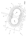
Figure 2 shows a plan view, with parts removed for clarity, of theFigure 1 laser marking unit; -
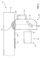
Figure 3 shows a schematic side view, with parts removed for clarity, of a laser marking device of theFigure 1 laser marking unit; -
Figure 4 shows a schematic underside view, with parts removed for clarity, of the laser marking device inFigure 3 ; -
Figures 5 and 6 show schematics of two deflection boxes of theFigure 3 laser marking device. -
Number 1 inFigure 1 indicates as a whole a marking unit for marking a progressive code (normally an alphanumeric and/or bar code) on the outer surface of packets 2 of cigarettes. Themarking unit 1 shown inFigure 1 is very similar to the one described in Patent ApplicationEP1916188A1 , which is included herein by way of reference. Packets 2 of cigarettes are fed to markingunit 1 on an input belt conveyor 3, which receives a succession of packets 2 of cigarettes, arranged in single file, from a packing machine (not shown); and from markingunit 1, packets 2 of cigarettes are fed onto an output belt conveyor 4, which feeds a succession of packets 2 of cigarettes, arranged in single file, to a cellophaning machine (not shown). -
Marking unit 1 comprises aframe 5 resting on feet on the floor and supporting ahorizontal marking conveyor 6, which feeds packets 2 of cigarettes along a marking path P extending between aninput station 7 at the output end of input conveyor 3, and an output station 8 at the input end of output conveyor 4. - As shown in
Figure 2 , markingconveyor 6 comprises anendless belt 9 looped about twohorizontal end pulleys rotation 11. Preferably, one end pulley 10 is powered to rotate continuously about respective central axis ofrotation 11, while the other pulley 10 is idle. Consequently, path P comprises a curved, arc-shaped initial portion T1 extending aboutend pulley 10a; a straight intermediate portion T2 extending betweenend pulleys end pulley 10b; a straight intermediate portion T4 extending betweenend pulleys end pulley 10a. - A number of
pockets 12 are defined alongbelt 9, each for housing a respective packet 2 of cigarettes. More specifically, eachpocket 12 receives a respective packet 2 of cigarettes from input conveyor 3 atinput station 7, and releases respective packet 2 of cigarettes to output conveyor 4 at output station 8.Belt 9 supports a number ofgrippers 13, each perpendicular to belt 9 and defining a wall of arespective pocket 12. In other words, eachpocket 12 is defined and bounded by two consecutive, side byside grippers 13. - In a preferred embodiment, marking
conveyor 6 comprises asupport 14 beneath markingconveyor 6 and having ahorizontal top wall 15, on which packets 2 of cigarettes slide, pushed along bypockets 12 of markingconveyor 6. -
Marking unit 1 also comprises amarking station 16 located along markingconveyor 6, betweeninput station 7 and output station 8, and in particular along straight intermediate portion T2 of marking path P, betweenend pulley 10a andend pulley 10b.Marking station 16 comprises alaser marking device 17 for marking a code on the outer surface of each packet 2 of cigarettes on markingconveyor 6. - As shown in
Figure 3 ,laser marking device 17 comprises alaser beam generator 18 for emitting a laser beam by means of anemitter 19; and adeflection box 20 connected mechanically togenerator 18 to deflect the laser beam onto the packet 2 of cigarettes at (i.e. travelling through)marking station 16, to mark the progressive code on the outer surface of packet 2 of cigarettes. -
Deflection box 20 comprises a supportingbox 21 housing a number ofmirrors 22 for deflecting the laser beam. In a preferred embodiment, eachmirror 22 is defined by a circular plate of mirror-polished copper and fixed insidebox 21 by respective screws. More specifically,mirrors 22 ofdeflection box 20 define a focusingpath 23, along which the laser beam travels in use, and which starts atemitter 19, and ends on the outer surface of the packet 2 of cigarettes atmarking station 16.Deflection box 20 is connected mechanically tolaser beam generator 18 for easy removal and replacement. - In a preferred embodiment shown in
Figure 4 ,deflection box 20 is screwed to twotelescopic guides 24, which slide between a work position (shown by the continuous line inFigure 4 ), in whichdeflection box 20 is connected tolaser beam generator 18 atemitter 19, and a change position (shown partly by the dash line inFigure 4 ), in whichdeflection box 20 is detached a fair distance fromlaser beam generator 18 and substantially free on all sides.Telescopic guides 24 serve to movedeflection box 20 quickly and easily into the change position, in whichdeflection box 20 is free on all sides and therefore quickly and easily replaceable.Deflection box 20 is preferably fitted with ahandle 25, by which to movedeflection box 20 easily between the work position and the change position. - A preferred embodiment shown in
Figures 3 and4 has asafety shutter 26 mounted to slide between an open position (shown by the continuous line inFigures 3 and4 ), in whichsafety shutter 26 is moved with respect toemitter 19 to permit emission of the laser beam, and a closed position (shown partly by the dash line inFigures 3 and4 ), in whichsafety shutter 26 coversemitter 19 to prevent emission of the laser beam. Shutter 26 is fitted with an elastic body (typically a spring) to pushshutter 26 into the closed position, and is connected mechanically totelescopic guides 24 so that, in the work position,telescopic guides 24push shutter 26 into the open position in opposition toelastic body 27, and, whentelescopic guides 24 are in the change position,shutter 26 is moved freely into the closed position byelastic body 27. - As shown in
Figures 5 and 6 , at least two different,interchangeable deflection boxes deflection box 20a is designed to mark a progressive code on anend wall 28 of a packet 2 of cigarettes moving throughmarking station 16 on markingconveyor 6; anddeflection box 20b is designed to mark a progressive code on a lateral wall 29 (perpendicular and adjacent to end wall 28) of a packet 2 of cigarettes moving throughmarking station 16 on markingconveyor 6. More specifically,deflection box 20a comprises onemirror 22, whiledeflection box 20b comprises twomirrors 22. A particular feature ofdeflection boxes respective focusing paths 23 are exactly the same length and equal to the focal length oflaser beam generator 18. That is, in bothdeflection boxes emitter 19 to the outer surface of packet 2 of cigarettes atmarking station 16 is identical and equal to the focal length oflaser beam generator 18. Consequently, regardless of whichdeflection box 20 is fitted tolaser beam generator 18, the laser beam is perfectly focused on the outer surface of packet 2 of cigarettes atmarking station 16. - By way of example,
Figures 5 and 6 show twodifferent deflection boxes deflection boxes 20, however, may obviously be provided to accordingly increase the number of marking locations on packets 2 of cigarettes. -
Laser marking unit 1 as described above has numerous advantages, by being cheap and easy to produce and, above all, by enabling fast, easy alteration to the marking location on packets 2 of cigarettes. More specifically, one operator need simply remove thedeflection box 20 currently fitted tolaser beam generator 18, and replace it with anotherdeflection box 20 to alter the marking location on packets 2 of cigarettes. In this connection, it is important to point out thatdeflection boxes 20 are compact (a few dm3 in total volume) and lightweight (normally less than 5 kg) enough to be handled easily by one operator, and to be stored easily, even on markingunit 1 itself. - In view of its many advantages, marking
unit 1 described above may also be used to advantage for marking codes or similar on packets 2 other than packets 2 of cigarettes, e.g. for marking codes on cartons of cigarettes, on boxes, or on packages of food products.
Claims (8)
- A laser marking unit (1) for marking packets (2), comprising:a marking conveyor (6) for feeding the packets (2) successively along a marking path (P); anda marking station (16) located along the marking conveyor (6), and comprising a laser marking device (17) for marking a code on the outer surface of each packet (2) conveyed on the marking conveyor (6);the laser marking device (17) comprises a laser beam generator (18) which emits a laser beam by means of an emitter (19); and a deflection box (20) which deflects the laser beam onto the packet (2) at the marking station (16) by directing the laser beam along a focusing path (23) that starts at the emitter (19) and terminates on the outer surface of the packet (2);the marking unit (1) being characterized in that:the deflection box (20) is mechanically connected removably, and therefore replaceably, to the generator (18);at least two different, interchangeable deflection boxes (20a, 20b) are provided; andin both deflection boxes (20a, 20b), the corresponding focusing paths (23) are exactly the same length, which equals a focal length of the laser beam generator (18).
- A marking unit (1) as claimed in Claim 1, wherein :a first deflection box (20a) marks the progressive code on an end wall (28) of a packet (2) fed through the marking station (16) on the marking conveyor (6); anda second deflection box (20b) marks the progressive code on a lateral wall (29) of a packet (2) fed through the marking station (16) on the marking conveyor (6).
- A marking unit (1) as claimed in Claim 2, wherein the first deflection box (20a) comprises one mirror (22), and the second deflection box (20b) comprises two mirrors (22).
- A marking unit (1) as claimed in Claim 1, 2 or 3, wherein each deflection box (20) comprises a supporting body (21) housing a number of mirrors (22) for deflecting the laser beam.
- A marking unit (1) as claimed in one of Claims 1 to 4, and comprising at least one telescopic guide (24) which supports the deflection box (20) mounted on the laser beam generator (18), and is movable between a work position in which the deflection box (20) is connected to the laser beam generator (18) at the emitter (19), and a change position in which the deflection box (20) is disconnected from the laser beam generator (18) and substantially free on all sides.
- A marking unit (1) as claimed in Claim 5, and comprising a safety shutter (26) which is mounted to move between an open position in which the safety shutter (26) is shifted with respect to the emitter (19) to permit emission of the laser beam, and a closed position in which the safety shutter (26) covers the emitter (19) to prevent emission of the laser beam.
- A marking unit (1) as claimed in Claim 6, wherein the safety shutter (26) is fitted with an elastic body (27) which pushes the safety shutter (26) into the closed position.
- A marking unit (1) as claimed in Claim 7, wherein the safety shutter (26) is connected mechanically to the telescopic guides (24) so that the telescopic guides (24) in the work position push the safety shutter (26) into the open position in opposition to the elastic body (27), and, when the telescopic guides (24) are in the change position, the safety shutter (26) is moved freely into the closed position by the elastic body (27).
Applications Claiming Priority (1)
| Application Number | Priority Date | Filing Date | Title |
|---|---|---|---|
| ITBO2008A000604A IT1391351B1 (en) | 2008-10-06 | 2008-10-06 | PACKAGE LASER MARKING UNIT. |
Publications (2)
| Publication Number | Publication Date |
|---|---|
| EP2172399A1 true EP2172399A1 (en) | 2010-04-07 |
| EP2172399B1 EP2172399B1 (en) | 2012-09-19 |
Family
ID=41329540
Family Applications (1)
| Application Number | Title | Priority Date | Filing Date |
|---|---|---|---|
| EP09172261A Active EP2172399B1 (en) | 2008-10-06 | 2009-10-05 | Laser packet marking unit |
Country Status (4)
| Country | Link |
|---|---|
| US (1) | US8248443B2 (en) |
| EP (1) | EP2172399B1 (en) |
| JP (1) | JP5468865B2 (en) |
| IT (1) | IT1391351B1 (en) |
Cited By (9)
| Publication number | Priority date | Publication date | Assignee | Title |
|---|---|---|---|---|
| CN102173220A (en) * | 2011-01-27 | 2011-09-07 | 广东烟草云浮市有限责任公司 | Cigarette common laser code-printing equipment and code-printing method thereof |
| CN102275389A (en) * | 2011-06-25 | 2011-12-14 | 江苏宏宝锻造有限公司 | Mistake-proofing device applied on laser marking machine |
| ITBO20130638A1 (en) * | 2013-11-25 | 2015-05-26 | Gd Spa | LASER PRINTING UNITS AND METHOD OF A PACKAGE FOR PRINTING TWO DIFFERENT PARTS OF THE PACKAGE. |
| CN106005626A (en) * | 2016-07-18 | 2016-10-12 | 江苏佳华新材料科技有限公司 | Box-packed chemical transmission, separation, coding and sorting system |
| CN107379780A (en) * | 2017-08-09 | 2017-11-24 | 东莞市叁和激光科技有限公司 | A laser marking machine for food packaging bags |
| CN111907771A (en) * | 2020-08-03 | 2020-11-10 | 云南中烟工业有限责任公司 | Method for improving closing performance of cigarette packaging box with medium cigarette specification |
| WO2022011997A1 (en) * | 2020-05-23 | 2022-01-20 | 达科为(深圳)医疗设备有限公司 | Laser marking machine for embedding box |
| CN114799584A (en) * | 2022-06-06 | 2022-07-29 | 深圳市大德激光技术有限公司 | Automatic loading and unloading device for ultrafast laser precision machining |
| DE112021004921T5 (en) | 2020-09-21 | 2023-07-20 | G.D Societa' Per Azioni | Manufacturing method and machine to manufacture a rigid pack of smoking products |
Families Citing this family (3)
| Publication number | Priority date | Publication date | Assignee | Title |
|---|---|---|---|---|
| CN108528055B (en) * | 2018-02-13 | 2019-07-26 | 中国烟草总公司北京市公司物流中心 | Cigarette bar coding system and method |
| CN108993926A (en) * | 2018-07-29 | 2018-12-14 | 广东广凌信息科技股份有限公司 | A kind of Smart library also book sorting system automatically |
| CN114633567B (en) * | 2022-02-22 | 2023-02-21 | 江苏省烟草公司盐城市公司 | Laser coding device and method for sorting cigarettes |
Citations (7)
| Publication number | Priority date | Publication date | Assignee | Title |
|---|---|---|---|---|
| WO1992003297A1 (en) * | 1990-08-15 | 1992-03-05 | United Distillers Plc | Sub-surface marking |
| DE4237577A1 (en) * | 1991-11-10 | 1993-05-27 | A A A Software Consulting & Mf | Container re-filling code marking device - detects previously marked container code for positioning container relative to marking device to prevent codes overlapping |
| GB2337974A (en) * | 1998-06-03 | 1999-12-08 | Gd Spa | Conveyor for a printing station |
| US20010032932A1 (en) | 2000-01-31 | 2001-10-25 | Heinz Focke | Process and apparatus for providing codings on ( cigarette ) packs |
| US20050134678A1 (en) * | 2003-12-19 | 2005-06-23 | Kevin Franklin | Striping and clipping correction |
| EP1605293A1 (en) * | 2004-06-09 | 2005-12-14 | Sator Laser GmbH | Device for labelling of objects with a laser beam |
| EP1916188A1 (en) | 2006-10-23 | 2008-04-30 | G.D Societ Per Azioni | Packet printing unit |
Family Cites Families (6)
| Publication number | Priority date | Publication date | Assignee | Title |
|---|---|---|---|---|
| JPS62244591A (en) * | 1986-04-15 | 1987-10-24 | Nec Corp | Multi-head laser marker |
| GB8700765D0 (en) * | 1987-01-14 | 1987-02-18 | Wiggins Teape Group Ltd | Laser apparatus |
| JPH0970678A (en) * | 1995-09-06 | 1997-03-18 | Fuji Electric Co Ltd | Laser marking device |
| EP1237031B1 (en) * | 2001-02-23 | 2004-12-15 | Leica Microsystems Schweiz AG | Optical instrument or apparatus for binocular viewing |
| JP2003344792A (en) * | 2002-05-29 | 2003-12-03 | Central Glass Co Ltd | How to draw glass |
| KR20040046422A (en) * | 2002-11-27 | 2004-06-05 | 주식회사 이오테크닉스 | Laser system for 1064/532 nm wave length and chip scale marker having thereof |
-
2008
- 2008-10-06 IT ITBO2008A000604A patent/IT1391351B1/en active
-
2009
- 2009-10-01 US US12/571,741 patent/US8248443B2/en not_active Expired - Fee Related
- 2009-10-05 EP EP09172261A patent/EP2172399B1/en active Active
- 2009-10-06 JP JP2009232696A patent/JP5468865B2/en not_active Expired - Fee Related
Patent Citations (8)
| Publication number | Priority date | Publication date | Assignee | Title |
|---|---|---|---|---|
| WO1992003297A1 (en) * | 1990-08-15 | 1992-03-05 | United Distillers Plc | Sub-surface marking |
| DE4237577A1 (en) * | 1991-11-10 | 1993-05-27 | A A A Software Consulting & Mf | Container re-filling code marking device - detects previously marked container code for positioning container relative to marking device to prevent codes overlapping |
| GB2337974A (en) * | 1998-06-03 | 1999-12-08 | Gd Spa | Conveyor for a printing station |
| US6098533A (en) | 1998-06-03 | 2000-08-08 | G. D. Societa Per Azioni | Conveyor for stabilizing packets of cigarettes coming off a packing machine |
| US20010032932A1 (en) | 2000-01-31 | 2001-10-25 | Heinz Focke | Process and apparatus for providing codings on ( cigarette ) packs |
| US20050134678A1 (en) * | 2003-12-19 | 2005-06-23 | Kevin Franklin | Striping and clipping correction |
| EP1605293A1 (en) * | 2004-06-09 | 2005-12-14 | Sator Laser GmbH | Device for labelling of objects with a laser beam |
| EP1916188A1 (en) | 2006-10-23 | 2008-04-30 | G.D Societ Per Azioni | Packet printing unit |
Cited By (11)
| Publication number | Priority date | Publication date | Assignee | Title |
|---|---|---|---|---|
| CN102173220A (en) * | 2011-01-27 | 2011-09-07 | 广东烟草云浮市有限责任公司 | Cigarette common laser code-printing equipment and code-printing method thereof |
| CN102275389A (en) * | 2011-06-25 | 2011-12-14 | 江苏宏宝锻造有限公司 | Mistake-proofing device applied on laser marking machine |
| ITBO20130638A1 (en) * | 2013-11-25 | 2015-05-26 | Gd Spa | LASER PRINTING UNITS AND METHOD OF A PACKAGE FOR PRINTING TWO DIFFERENT PARTS OF THE PACKAGE. |
| CN106005626A (en) * | 2016-07-18 | 2016-10-12 | 江苏佳华新材料科技有限公司 | Box-packed chemical transmission, separation, coding and sorting system |
| CN107379780A (en) * | 2017-08-09 | 2017-11-24 | 东莞市叁和激光科技有限公司 | A laser marking machine for food packaging bags |
| WO2022011997A1 (en) * | 2020-05-23 | 2022-01-20 | 达科为(深圳)医疗设备有限公司 | Laser marking machine for embedding box |
| CN111907771A (en) * | 2020-08-03 | 2020-11-10 | 云南中烟工业有限责任公司 | Method for improving closing performance of cigarette packaging box with medium cigarette specification |
| CN111907771B (en) * | 2020-08-03 | 2022-04-01 | 云南中烟工业有限责任公司 | Method for improving closing performance of cigarette packaging box with medium cigarette specification |
| DE112021004921T5 (en) | 2020-09-21 | 2023-07-20 | G.D Societa' Per Azioni | Manufacturing method and machine to manufacture a rigid pack of smoking products |
| CN114799584A (en) * | 2022-06-06 | 2022-07-29 | 深圳市大德激光技术有限公司 | Automatic loading and unloading device for ultrafast laser precision machining |
| CN114799584B (en) * | 2022-06-06 | 2024-05-10 | 深圳市大德激光技术有限公司 | Automatic feeding and discharging device for ultra-fast laser precision machining |
Also Published As
| Publication number | Publication date |
|---|---|
| EP2172399B1 (en) | 2012-09-19 |
| ITBO20080604A1 (en) | 2010-04-07 |
| JP2010089161A (en) | 2010-04-22 |
| IT1391351B1 (en) | 2011-12-13 |
| US20100085413A1 (en) | 2010-04-08 |
| US8248443B2 (en) | 2012-08-21 |
| JP5468865B2 (en) | 2014-04-09 |
Similar Documents
| Publication | Publication Date | Title |
|---|---|---|
| EP2172399B1 (en) | Laser packet marking unit | |
| JP6240047B2 (en) | Spouted bag feeder | |
| EP1916188B1 (en) | Packet printing unit | |
| KR101381446B1 (en) | Roots and stems of onion cutting device | |
| CY1108550T1 (en) | PACKAGING MACHINE FOR CORRESPONDENT PILLARS | |
| AU2016234766B2 (en) | Bag making and packaging machine | |
| US7722027B2 (en) | Vacuum belt conveyor | |
| JP5550275B2 (en) | Object sorting device | |
| ITMO20020298A1 (en) | MACHINE FOR THE PACKAGING OF CONTAINING CARTONS | |
| CN101612999A (en) | A kind of air suction conveying and positioning device for cigarette package cellophane | |
| KR970010620A (en) | Pusher device of lead frame | |
| MX2007012343A (en) | Device and method for transporting elongate food products. | |
| ES2096003T3 (en) | DEVICE FOR ADJUSTING THE ACCOMMODATION VOLUME OF A PIECE HOLDER. | |
| JP2011025134A (en) | Object sorter | |
| KR960700949A (en) | METHOD OF CONTINUOUSLY FEEDING FLAT ARTICLES FROM A STACK | |
| GB2104027A (en) | Apparatus for the transport of articles | |
| SE9701025L (en) | Device for feeding leaves from a store of leaves | |
| KR100952961B1 (en) | Transfer tape automatic cutting machine | |
| CN208289232U (en) | A kind of coiled strip hi-precision cutting equipment | |
| CN108213742A (en) | A kind of coiled strip hi-precision cutting equipment | |
| DE50207054D1 (en) | log stacker | |
| JP6676433B2 (en) | Automatic screw feeder | |
| EP1714878B1 (en) | Overwrapping machine for packets of cigarettes | |
| EP1050463A3 (en) | Tying machine for tying a stack of articles | |
| JPS6131628B2 (en) |
Legal Events
| Date | Code | Title | Description |
|---|---|---|---|
| PUAI | Public reference made under article 153(3) epc to a published international application that has entered the european phase |
Free format text: ORIGINAL CODE: 0009012 |
|
| 17P | Request for examination filed |
Effective date: 20100219 |
|
| AK | Designated contracting states |
Kind code of ref document: A1 Designated state(s): AT BE BG CH CY CZ DE DK EE ES FI FR GB GR HR HU IE IS IT LI LT LU LV MC MK MT NL NO PL PT RO SE SI SK SM TR |
|
| AX | Request for extension of the european patent |
Extension state: AL BA RS |
|
| RIC1 | Information provided on ipc code assigned before grant |
Ipc: B65B 61/26 20060101ALI20120223BHEP Ipc: B65B 59/00 20060101AFI20120223BHEP Ipc: B65B 59/04 20060101ALN20120223BHEP |
|
| GRAP | Despatch of communication of intention to grant a patent |
Free format text: ORIGINAL CODE: EPIDOSNIGR1 |
|
| RIC1 | Information provided on ipc code assigned before grant |
Ipc: B65B 59/04 20060101ALN20120316BHEP Ipc: B65B 61/26 20060101ALI20120316BHEP Ipc: B65B 59/00 20060101AFI20120316BHEP |
|
| GRAS | Grant fee paid |
Free format text: ORIGINAL CODE: EPIDOSNIGR3 |
|
| GRAA | (expected) grant |
Free format text: ORIGINAL CODE: 0009210 |
|
| AK | Designated contracting states |
Kind code of ref document: B1 Designated state(s): AT BE BG CH CY CZ DE DK EE ES FI FR GB GR HR HU IE IS IT LI LT LU LV MC MK MT NL NO PL PT RO SE SI SK SM TR |
|
| REG | Reference to a national code |
Ref country code: GB Ref legal event code: FG4D |
|
| REG | Reference to a national code |
Ref country code: CH Ref legal event code: EP |
|
| REG | Reference to a national code |
Ref country code: IE Ref legal event code: FG4D |
|
| REG | Reference to a national code |
Ref country code: AT Ref legal event code: REF Ref document number: 575874 Country of ref document: AT Kind code of ref document: T Effective date: 20121015 |
|
| REG | Reference to a national code |
Ref country code: DE Ref legal event code: R096 Ref document number: 602009009772 Country of ref document: DE Effective date: 20121115 |
|
| REG | Reference to a national code |
Ref country code: CH Ref legal event code: NV Representative=s name: HEPP WENGER RYFFEL AG, CH |
|
| PG25 | Lapsed in a contracting state [announced via postgrant information from national office to epo] |
Ref country code: LT Free format text: LAPSE BECAUSE OF FAILURE TO SUBMIT A TRANSLATION OF THE DESCRIPTION OR TO PAY THE FEE WITHIN THE PRESCRIBED TIME-LIMIT Effective date: 20120919 Ref country code: CY Free format text: LAPSE BECAUSE OF FAILURE TO SUBMIT A TRANSLATION OF THE DESCRIPTION OR TO PAY THE FEE WITHIN THE PRESCRIBED TIME-LIMIT Effective date: 20120919 Ref country code: HR Free format text: LAPSE BECAUSE OF FAILURE TO SUBMIT A TRANSLATION OF THE DESCRIPTION OR TO PAY THE FEE WITHIN THE PRESCRIBED TIME-LIMIT Effective date: 20120919 Ref country code: FI Free format text: LAPSE BECAUSE OF FAILURE TO SUBMIT A TRANSLATION OF THE DESCRIPTION OR TO PAY THE FEE WITHIN THE PRESCRIBED TIME-LIMIT Effective date: 20120919 Ref country code: NO Free format text: LAPSE BECAUSE OF FAILURE TO SUBMIT A TRANSLATION OF THE DESCRIPTION OR TO PAY THE FEE WITHIN THE PRESCRIBED TIME-LIMIT Effective date: 20121219 |
|
| REG | Reference to a national code |
Ref country code: NL Ref legal event code: VDEP Effective date: 20120919 |
|
| REG | Reference to a national code |
Ref country code: AT Ref legal event code: MK05 Ref document number: 575874 Country of ref document: AT Kind code of ref document: T Effective date: 20120919 |
|
| REG | Reference to a national code |
Ref country code: LT Ref legal event code: MG4D Effective date: 20120919 |
|
| PG25 | Lapsed in a contracting state [announced via postgrant information from national office to epo] |
Ref country code: LV Free format text: LAPSE BECAUSE OF FAILURE TO SUBMIT A TRANSLATION OF THE DESCRIPTION OR TO PAY THE FEE WITHIN THE PRESCRIBED TIME-LIMIT Effective date: 20120919 Ref country code: SE Free format text: LAPSE BECAUSE OF FAILURE TO SUBMIT A TRANSLATION OF THE DESCRIPTION OR TO PAY THE FEE WITHIN THE PRESCRIBED TIME-LIMIT Effective date: 20120919 Ref country code: GR Free format text: LAPSE BECAUSE OF FAILURE TO SUBMIT A TRANSLATION OF THE DESCRIPTION OR TO PAY THE FEE WITHIN THE PRESCRIBED TIME-LIMIT Effective date: 20121220 Ref country code: SI Free format text: LAPSE BECAUSE OF FAILURE TO SUBMIT A TRANSLATION OF THE DESCRIPTION OR TO PAY THE FEE WITHIN THE PRESCRIBED TIME-LIMIT Effective date: 20120919 |
|
| PG25 | Lapsed in a contracting state [announced via postgrant information from national office to epo] |
Ref country code: RO Free format text: LAPSE BECAUSE OF FAILURE TO SUBMIT A TRANSLATION OF THE DESCRIPTION OR TO PAY THE FEE WITHIN THE PRESCRIBED TIME-LIMIT Effective date: 20120919 Ref country code: ES Free format text: LAPSE BECAUSE OF FAILURE TO SUBMIT A TRANSLATION OF THE DESCRIPTION OR TO PAY THE FEE WITHIN THE PRESCRIBED TIME-LIMIT Effective date: 20121230 Ref country code: IS Free format text: LAPSE BECAUSE OF FAILURE TO SUBMIT A TRANSLATION OF THE DESCRIPTION OR TO PAY THE FEE WITHIN THE PRESCRIBED TIME-LIMIT Effective date: 20130119 Ref country code: NL Free format text: LAPSE BECAUSE OF FAILURE TO SUBMIT A TRANSLATION OF THE DESCRIPTION OR TO PAY THE FEE WITHIN THE PRESCRIBED TIME-LIMIT Effective date: 20120919 Ref country code: BE Free format text: LAPSE BECAUSE OF FAILURE TO SUBMIT A TRANSLATION OF THE DESCRIPTION OR TO PAY THE FEE WITHIN THE PRESCRIBED TIME-LIMIT Effective date: 20120919 Ref country code: EE Free format text: LAPSE BECAUSE OF FAILURE TO SUBMIT A TRANSLATION OF THE DESCRIPTION OR TO PAY THE FEE WITHIN THE PRESCRIBED TIME-LIMIT Effective date: 20120919 Ref country code: CZ Free format text: LAPSE BECAUSE OF FAILURE TO SUBMIT A TRANSLATION OF THE DESCRIPTION OR TO PAY THE FEE WITHIN THE PRESCRIBED TIME-LIMIT Effective date: 20120919 |
|
| PG25 | Lapsed in a contracting state [announced via postgrant information from national office to epo] |
Ref country code: PT Free format text: LAPSE BECAUSE OF FAILURE TO SUBMIT A TRANSLATION OF THE DESCRIPTION OR TO PAY THE FEE WITHIN THE PRESCRIBED TIME-LIMIT Effective date: 20130121 Ref country code: PL Free format text: LAPSE BECAUSE OF FAILURE TO SUBMIT A TRANSLATION OF THE DESCRIPTION OR TO PAY THE FEE WITHIN THE PRESCRIBED TIME-LIMIT Effective date: 20120919 Ref country code: MC Free format text: LAPSE BECAUSE OF NON-PAYMENT OF DUE FEES Effective date: 20121031 Ref country code: SK Free format text: LAPSE BECAUSE OF FAILURE TO SUBMIT A TRANSLATION OF THE DESCRIPTION OR TO PAY THE FEE WITHIN THE PRESCRIBED TIME-LIMIT Effective date: 20120919 |
|
| PG25 | Lapsed in a contracting state [announced via postgrant information from national office to epo] |
Ref country code: AT Free format text: LAPSE BECAUSE OF FAILURE TO SUBMIT A TRANSLATION OF THE DESCRIPTION OR TO PAY THE FEE WITHIN THE PRESCRIBED TIME-LIMIT Effective date: 20120919 |
|
| REG | Reference to a national code |
Ref country code: IE Ref legal event code: MM4A |
|
| PLBE | No opposition filed within time limit |
Free format text: ORIGINAL CODE: 0009261 |
|
| REG | Reference to a national code |
Ref country code: FR Ref legal event code: ST Effective date: 20130628 |
|
| STAA | Information on the status of an ep patent application or granted ep patent |
Free format text: STATUS: NO OPPOSITION FILED WITHIN TIME LIMIT |
|
| PG25 | Lapsed in a contracting state [announced via postgrant information from national office to epo] |
Ref country code: BG Free format text: LAPSE BECAUSE OF FAILURE TO SUBMIT A TRANSLATION OF THE DESCRIPTION OR TO PAY THE FEE WITHIN THE PRESCRIBED TIME-LIMIT Effective date: 20121219 Ref country code: IE Free format text: LAPSE BECAUSE OF NON-PAYMENT OF DUE FEES Effective date: 20121005 Ref country code: DK Free format text: LAPSE BECAUSE OF FAILURE TO SUBMIT A TRANSLATION OF THE DESCRIPTION OR TO PAY THE FEE WITHIN THE PRESCRIBED TIME-LIMIT Effective date: 20120919 |
|
| 26N | No opposition filed |
Effective date: 20130620 |
|
| PG25 | Lapsed in a contracting state [announced via postgrant information from national office to epo] |
Ref country code: FR Free format text: LAPSE BECAUSE OF NON-PAYMENT OF DUE FEES Effective date: 20121119 Ref country code: IT Free format text: LAPSE BECAUSE OF FAILURE TO SUBMIT A TRANSLATION OF THE DESCRIPTION OR TO PAY THE FEE WITHIN THE PRESCRIBED TIME-LIMIT Effective date: 20120919 |
|
| REG | Reference to a national code |
Ref country code: DE Ref legal event code: R097 Ref document number: 602009009772 Country of ref document: DE Effective date: 20130620 |
|
| PG25 | Lapsed in a contracting state [announced via postgrant information from national office to epo] |
Ref country code: MT Free format text: LAPSE BECAUSE OF FAILURE TO SUBMIT A TRANSLATION OF THE DESCRIPTION OR TO PAY THE FEE WITHIN THE PRESCRIBED TIME-LIMIT Effective date: 20120919 |
|
| PG25 | Lapsed in a contracting state [announced via postgrant information from national office to epo] |
Ref country code: TR Free format text: LAPSE BECAUSE OF FAILURE TO SUBMIT A TRANSLATION OF THE DESCRIPTION OR TO PAY THE FEE WITHIN THE PRESCRIBED TIME-LIMIT Effective date: 20120919 |
|
| PG25 | Lapsed in a contracting state [announced via postgrant information from national office to epo] |
Ref country code: SM Free format text: LAPSE BECAUSE OF FAILURE TO SUBMIT A TRANSLATION OF THE DESCRIPTION OR TO PAY THE FEE WITHIN THE PRESCRIBED TIME-LIMIT Effective date: 20120919 Ref country code: LU Free format text: LAPSE BECAUSE OF NON-PAYMENT OF DUE FEES Effective date: 20121005 |
|
| REG | Reference to a national code |
Ref country code: CH Ref legal event code: PL |
|
| GBPC | Gb: european patent ceased through non-payment of renewal fee |
Effective date: 20131005 |
|
| PG25 | Lapsed in a contracting state [announced via postgrant information from national office to epo] |
Ref country code: HU Free format text: LAPSE BECAUSE OF FAILURE TO SUBMIT A TRANSLATION OF THE DESCRIPTION OR TO PAY THE FEE WITHIN THE PRESCRIBED TIME-LIMIT Effective date: 20091005 Ref country code: GB Free format text: LAPSE BECAUSE OF NON-PAYMENT OF DUE FEES Effective date: 20131005 Ref country code: LI Free format text: LAPSE BECAUSE OF NON-PAYMENT OF DUE FEES Effective date: 20131031 Ref country code: CH Free format text: LAPSE BECAUSE OF NON-PAYMENT OF DUE FEES Effective date: 20131031 |
|
| PG25 | Lapsed in a contracting state [announced via postgrant information from national office to epo] |
Ref country code: MK Free format text: LAPSE BECAUSE OF FAILURE TO SUBMIT A TRANSLATION OF THE DESCRIPTION OR TO PAY THE FEE WITHIN THE PRESCRIBED TIME-LIMIT Effective date: 20120919 |
|
| PGFP | Annual fee paid to national office [announced via postgrant information from national office to epo] |
Ref country code: DE Payment date: 20251029 Year of fee payment: 17 |