EP2170634B1 - Jounce bumper assembly and gas spring assembly including same - Google Patents
Jounce bumper assembly and gas spring assembly including same Download PDFInfo
- Publication number
- EP2170634B1 EP2170634B1 EP08770174.4A EP08770174A EP2170634B1 EP 2170634 B1 EP2170634 B1 EP 2170634B1 EP 08770174 A EP08770174 A EP 08770174A EP 2170634 B1 EP2170634 B1 EP 2170634B1
- Authority
- EP
- European Patent Office
- Prior art keywords
- bumper
- retainer
- side wall
- jounce
- wall
- Prior art date
- Legal status (The legal status is an assumption and is not a legal conclusion. Google has not performed a legal analysis and makes no representation as to the accuracy of the status listed.)
- Not-in-force
Links
- 239000000463 material Substances 0.000 claims description 15
- 239000000725 suspension Substances 0.000 claims description 15
- 238000006073 displacement reaction Methods 0.000 claims description 13
- 238000000034 method Methods 0.000 claims description 13
- 229920001971 elastomer Polymers 0.000 claims description 7
- 239000005060 rubber Substances 0.000 claims description 7
- 239000012858 resilient material Substances 0.000 claims description 3
- 229920002725 thermoplastic elastomer Polymers 0.000 claims description 3
- 229920002430 Fibre-reinforced plastic Polymers 0.000 claims description 2
- 230000006835 compression Effects 0.000 claims description 2
- 238000007906 compression Methods 0.000 claims description 2
- 239000011151 fibre-reinforced plastic Substances 0.000 claims description 2
- 239000002184 metal Substances 0.000 claims description 2
- 229920000642 polymer Polymers 0.000 claims description 2
- 238000004891 communication Methods 0.000 description 14
- 230000000712 assembly Effects 0.000 description 12
- 238000000429 assembly Methods 0.000 description 12
- 230000033001 locomotion Effects 0.000 description 10
- 238000010276 construction Methods 0.000 description 8
- 239000012530 fluid Substances 0.000 description 8
- 239000011324 bead Substances 0.000 description 4
- 230000005540 biological transmission Effects 0.000 description 4
- 239000006263 elastomeric foam Substances 0.000 description 3
- 239000006096 absorbing agent Substances 0.000 description 2
- 230000004075 alteration Effects 0.000 description 2
- 238000013016 damping Methods 0.000 description 2
- 230000003116 impacting effect Effects 0.000 description 2
- 238000012986 modification Methods 0.000 description 2
- 230000004048 modification Effects 0.000 description 2
- 238000005096 rolling process Methods 0.000 description 2
- 230000035939 shock Effects 0.000 description 2
- 150000001875 compounds Chemical class 0.000 description 1
- 230000001419 dependent effect Effects 0.000 description 1
- 239000000835 fiber Substances 0.000 description 1
- 239000004033 plastic Substances 0.000 description 1
- 229920003023 plastic Polymers 0.000 description 1
- 239000002990 reinforced plastic Substances 0.000 description 1
- 239000007787 solid Substances 0.000 description 1
- 239000003381 stabilizer Substances 0.000 description 1
- 238000012546 transfer Methods 0.000 description 1
- 238000013022 venting Methods 0.000 description 1
Images



Classifications
-
- F—MECHANICAL ENGINEERING; LIGHTING; HEATING; WEAPONS; BLASTING
- F16—ENGINEERING ELEMENTS AND UNITS; GENERAL MEASURES FOR PRODUCING AND MAINTAINING EFFECTIVE FUNCTIONING OF MACHINES OR INSTALLATIONS; THERMAL INSULATION IN GENERAL
- F16F—SPRINGS; SHOCK-ABSORBERS; MEANS FOR DAMPING VIBRATION
- F16F9/00—Springs, vibration-dampers, shock-absorbers, or similarly-constructed movement-dampers using a fluid or the equivalent as damping medium
- F16F9/02—Springs, vibration-dampers, shock-absorbers, or similarly-constructed movement-dampers using a fluid or the equivalent as damping medium using gas only or vacuum
- F16F9/04—Springs, vibration-dampers, shock-absorbers, or similarly-constructed movement-dampers using a fluid or the equivalent as damping medium using gas only or vacuum in a chamber with a flexible wall
- F16F9/05—Springs, vibration-dampers, shock-absorbers, or similarly-constructed movement-dampers using a fluid or the equivalent as damping medium using gas only or vacuum in a chamber with a flexible wall the flexible wall being of the rolling diaphragm type
- F16F9/052—Springs, vibration-dampers, shock-absorbers, or similarly-constructed movement-dampers using a fluid or the equivalent as damping medium using gas only or vacuum in a chamber with a flexible wall the flexible wall being of the rolling diaphragm type characterised by the bumper
-
- B—PERFORMING OPERATIONS; TRANSPORTING
- B60—VEHICLES IN GENERAL
- B60G—VEHICLE SUSPENSION ARRANGEMENTS
- B60G11/00—Resilient suspensions characterised by arrangement, location or kind of springs
- B60G11/32—Resilient suspensions characterised by arrangement, location or kind of springs having springs of different kinds
- B60G11/48—Resilient suspensions characterised by arrangement, location or kind of springs having springs of different kinds not including leaf springs
- B60G11/62—Resilient suspensions characterised by arrangement, location or kind of springs having springs of different kinds not including leaf springs having both rubber springs and fluid springs
-
- B—PERFORMING OPERATIONS; TRANSPORTING
- B60—VEHICLES IN GENERAL
- B60G—VEHICLE SUSPENSION ARRANGEMENTS
- B60G2202/00—Indexing codes relating to the type of spring, damper or actuator
- B60G2202/10—Type of spring
- B60G2202/14—Plastic spring, e.g. rubber
- B60G2202/143—Plastic spring, e.g. rubber subjected to compression
-
- B—PERFORMING OPERATIONS; TRANSPORTING
- B60—VEHICLES IN GENERAL
- B60G—VEHICLE SUSPENSION ARRANGEMENTS
- B60G2202/00—Indexing codes relating to the type of spring, damper or actuator
- B60G2202/10—Type of spring
- B60G2202/15—Fluid spring
- B60G2202/152—Pneumatic spring
-
- B—PERFORMING OPERATIONS; TRANSPORTING
- B60—VEHICLES IN GENERAL
- B60G—VEHICLE SUSPENSION ARRANGEMENTS
- B60G2204/00—Indexing codes related to suspensions per se or to auxiliary parts
- B60G2204/10—Mounting of suspension elements
- B60G2204/12—Mounting of springs or dampers
- B60G2204/126—Mounting of pneumatic springs
-
- B—PERFORMING OPERATIONS; TRANSPORTING
- B60—VEHICLES IN GENERAL
- B60G—VEHICLE SUSPENSION ARRANGEMENTS
- B60G2204/00—Indexing codes related to suspensions per se or to auxiliary parts
- B60G2204/40—Auxiliary suspension parts; Adjustment of suspensions
- B60G2204/45—Stops limiting travel
- B60G2204/4502—Stops limiting travel using resilient buffer
Definitions
- the subject matter of the present invention broadly relates to the art of vehicle suspension systems and, more particularly, to a jounce bumper assembly that is capable of dynamically tuned performance and a gas spring assembly including the same.
- Wheeled motor vehicles of most types and kinds include a sprung mass, such as a body or chassis, for example, and an unsprung mass, such as two or more axles or other wheel-engaging members, for example, with a suspension system disposed therebetween.
- a suspension system will include a plurality of spring devices as well as a plurality of damping devices that together permit the sprung and unsprung masses of the vehicle to move in a somewhat controlled manner relative to one another. Movement of the sprung and unsprung masses toward one another is normally referred to in the art as jounce motion while movement of the sprung and unsprung masses away from one another is commonly referred to in the art as rebound motion.
- the range of motion of a suspension system extends between a fully compressed condition and a fully extended condition.
- jounce bumpers are commonly installed on one or more portions of the vehicle to prevent such opposing portions from directly impacting one another.
- an opposing component will contact the jounce bumper rather than impacting the component on or near which the jounce bumper is mounted.
- Jounce bumpers of a variety of types, kinds and configurations have been developed and are commonly used. Though the size and shape of jounce bumpers vary widely, known jounce bumpers can generally be grouped into two categories, namely, compliant jounce bumpers and rigid jounce bumpers. The former are commonly formed from materials capable of relatively high deflections under load, and are often formed from rubber or elastomeric foam compounds. Generally, compliant jounce bumpers act to cushion or soften the impact that would otherwise be associated with a sudden movement toward a full jounce condition. As such, compliant jounce bumpers are well suited for use in relatively light duty applications, such as use in the suspension systems of passenger vehicles and light trucks, for example, where ride comfort is a more significant factor.
- the high axial deflections that would be associated with heavily loading a compliant jounce bumper would generate high corresponding lateral strains in the jounce bumper.
- materials that are well suited for comfortably cushioning impacts under full jounce conditions have been found to be poorly suited to such corresponding high levels of lateral strain, which can undesirably modify the performance characteristics of the compliant jounce bumper or even result in permanent deformation of the same.
- rigid jounce bumpers are commonly formed from materials that deflect a relatively small amount under load, such as high strength and/or fiber reinforced plastic materials, for example.
- Rigid jounce bumpers are not normally considered to be well suited for use in light duty applications (e.g., passenger vehicle applications) because of the minimal deflection and high impact associated with the use of such jounce bumpers.
- rigid jounce bumpers are well suited for heavy duty applications, such as in truck, tractor-trailer and other over-the-road vehicle applications, for example, where it is desirable to provide a sacrificial component that can prevent impacts between more permanent and/or expensive components.
- a jounce bumper that overcomes the forgoing and other disadvantages, such as, for example, by providing a jounce bumper for use in heavy duty applications that is capable of withstanding repeated impacts under the relatively high load conditions associated therewith, but which will also provide increased cushioning and reduced impact at least when initially contacted during jounce movement.
- An air spring assembly comprises a piston assembly which includes an outer shell and a structural insert.
- the structural insert is received in a shell cavity of the outer shell.
- the shell cavity has an open end.
- US 5 087 020 A discloses a cushion bearing for motor vehicles which has two rigid bearing seats with a resilient rubber bearing block and an air spring acting between the seats.
- a collar partially surrounds the bearing block. The collar acts as a stop to stabilize the bearing block laterally during compression.
- GB 1 248 025 A discloses a rolling bellows type air spring.
- the air spring comprises a rubber spring which is accommodated in a bowl and which is fixed to a piston of the air spring so as to project from the bowl.
- JP 4 004332 A relates to an air spring which includes an elastic member.
- the elastic member is arranged in a bowl-shaped receptacle.
- a gas spring assembly for use in forming an associated suspension system that is operative between an associated sprung mass and an associated unsprung mass of an associated vehicle.
- the gas spring assembly includes a first end member that is capable of being operatively connected to one of the associated sprung and unsprung masses, a second end member that is capable of being operatively connected to the other of the associated sprung and unsprung masses, and a flexible wall that includes first and second open ends.
- the flexible wall is disposed between the first and second end members to at least partially define a gas chamber therebetween.
- the first open end being secured on the first end member and the second open end being disposed along the second end member.
- An end closure includes a closure bottom wall and a closure side wall that extends from the closure bottom wall.
- a bumper retainer includes a retainer bottom wall and a retainer side wall that extends from the retainer bottom wall. The bumper retainer is supported on the second end member within the end closure such that the retainer bottom wall is disposed adjacent the closure bottom wall and the retainer side wall is disposed radially inwardly from the closure side wall.
- a resilient bumper includes a bumper top wall, a bumper bottom wall and a bumper side wall that extends therebetween.
- the resilient bumper also has a central axis extending between the bumper top and bottom walls.
- the resilient bumper is supported on the second end member and is received within the bumper retainer such that the bumper bottom wall is disposed along the closure bottom wall and at least a portion of the bumper side wall is disposed radially inwardly of the retainer side wall forming a free volume therebetween.
- the free volume is capable of permitting the retainer side wall to engage the bumper side wall under axial deflection of the jounce bumper to thereby restrict radially outward deflection of the jounce bumper.
- a gas spring assembly that includes a first end member and a second end member that is spaced from the first end member.
- a flexible wall of the assembly is disposed between the first and second end members and forms a substantially fluid-tight connection with each thereof to form a spring chamber therebetween.
- a jounce bumper of the assembly is supported within the spring chamber on one of the first and second end members.
- the jounce bumper includes an axis, a first bumper end wall, a second bumper end wall that is spaced from the first bumper end wall, and a bumper side wall that extends between the first and second bumper end walls.
- a bumper retainer of the assembly is supported within the spring chamber on one of the first and second end members.
- the bumper retainer includes an axis, a retainer bottom wall and a retainer side wall that extends from the retainer bottom wall toward an opposing open end.
- the jounce bumper and the bumper retainer are positioned within the spring chamber in approximately coaxial relation to one another, such that the bumper side wall and the retainer side wall extend at a non-zero angle relative to one another.
- a first radial gap is formed between the bumper side wall and the retainer side wall at a first axial position and a second radial gap between the bumper side wall and the retainer side wall is formed at a second axial position that is spaced from the first axial position.
- the first and second end members Upon axial displacement of the first and second bumper end walls toward one another due to relative movement of the first and second end members toward one another, the first and second end members compressively engage the jounce bumper therebetween.
- the bumper side wall and the retainer side wall abuttingly engage one another thereby at least partially resisting radially outward displacement of the jounce bumper, with the radially outward displacement being induced by the axial displacement of the jounce bumper.
- the bumper retainer is supported on the first end member with the open end disposed toward the second end member and the jounce bumper supported on the first end member within the bumper retainer.
- the second axial position is spaced from the first axial position in a direction extending away from the first end member such that the second radial gap is greater than the first radial gap.
- the jounce bumper has a bumper height and the bumper retainer may have a retainer height of from about 20 percent to about 80 percent of the bumper height.
- the bumper side wall and the retainer side wall are disposed at an angle relative to one another of from about 5 degrees to about 50 degrees.
- a jounce bumper assembly is provided that is capable of use within a spring chamber of a gas spring assembly.
- a gas spring assembly can include opposing end members that are secured to a flexible wall which at least partially forms the spring chamber therebetween.
- the jounce bumper assembly includes a resilient jounce bumper and a bumper retainer.
- the resilient jounce bumper includes an axis, a first bumper end wall, an opposing second bumper end wall and a bumper side wall extending between the first and second bumper end walls.
- the jounce bumper also has a bumper height.
- a bumper retainer includes an axis, a retainer bottom wall that extends approximately transverse to the axis and a retainer side wall that extends from the retainer bottom wall toward an opposing open end.
- the bumper retainer may have a retainer height of from about 20 percent to about 80 percent of the bumper height.
- the jounce bumper is approximately coaxially received within the bumper retainer such that the first bumper end wall is disposed in abutting engagement with at least a portion of the retainer bottom wall and such that the second bumper end wall projects outwardly from the open end of the bumper retainer such that the jounce bumper can be supported on an end closure of the gas spring assembly within the bumper retainer with the first bumper end wall disposed along the end closure and thereby captures the bumper retainer between the jounce bumper and the end closure.
- the bumper side wall and the retainer side wall extend at a non-zero angle relative to one another such that a free volume is formed therebetween.
- the free volume has a first radial gap between the bumper side wall and the retainer side wall at a first axial position and a second radial gap between the bumper side wall and the retainer side wall at a second axial position spaced from the first axial position.
- a method utilizing a jounce bumper assembly that is disposed between displaceably supported structural members.
- the method includes providing a jounce bumper that includes an axis, a first bumper end wall, a second bumper end wall spaced from the first bumper end wall, and a side wall extending between the first and second bumper end walls.
- the method also includes supporting the jounce bumper between the structural members such that the first bumper end wall is disposed along the end closure and thereby captures the bumper retainer between the jounce bumper and the end closure.
- the method further includes providing a bumper retainer that includes an axis, a retainer bottom wall and a retainer side wall extending from the retainer bottom wall toward an opposing open end.
- the method also includes supporting the bumper retainer between the structural members in approximately coaxial alignment with the jounce bumper.
- the method further includes compressing the jounce bumper in response to relative displacement of the structural members and thereby axially inwardly and radially outwardly deflecting the jounce bumper.
- the method also includes abuttingly engaging the bumper side wall and the retainer side wall and thereby at least partially restricting radially outward deflection of at least a portion of the jounce bumper, which radially outward deflection is at least partially due to the axially inward deflection.
- FIG. 1 illustrates a vehicle 100 having a sprung mass, such as a vehicle body 102, for example, and an unsprung mass, such as axles 104 and/or wheels 106, for example.
- a plurality of damping members such as shock absorbers 108, for example, can be secured between the sprung and unsprung masses of the vehicle in a suitable manner.
- a plurality of gas spring assemblies 110 are disposed in a suitable manner between the sprung and unsprung masses of the vehicle, such as adjacent wheels 106 and shock absorbers 108 as shown in FIG. 1 , for example.
- one or more of the plurality of gas spring assemblies can include a jounce bumper assembly 112 operatively associated therewith.
- Vehicle 100 also includes a pressurized gas supply system 114 that is in communication with gas spring assemblies 110 and that is operative to selectively supply pressurized gas thereto and exhaust pressurized gas therefrom.
- Gas supply system 114 includes a pressurized gas source, such as a compressor 116, and can optionally include a storage vessel, such as a reservoir 118, for example, for receiving and storing pressurized gas, such as may be generated by the pressurized gas source.
- System 114 can further include a suitable exhaust, such as a muffler 120, for example, for venting pressurized gas from the system.
- Gas supply system 114 can be in communication with the gas spring assemblies in any suitable manner.
- system 114 can include a valve assembly 122 or other suitable device or arrangement for selectively distributing pressurized gas to, from and/or between the pressurized gas source or sources, the exhaust and/or the gas spring assemblies.
- compressor 116, reservoir 118 and muffler 120 are in fluid communication with valve assembly 122 and can be selectively placed in fluid communication with one another therethrough.
- assemblies 110 are in fluid communication with valve assembly 122 via transmission lines 124 and, thus, can be selectively placed in communication with the compressor, reservoir, muffler and/or one another therethrough.
- valve assembly 122 can be selectively actuated to transfer pressurized gas from the compressor and/or reservoir to one or more of the gas spring assemblies. Additionally, valve assembly 122 can be selectively actuated to exhaust pressurized gas from one or more of the gas spring assemblies by way of muffler 120 or another suitable arrangement. It will be appreciated that the foregoing fluid supply system and operation thereof are merely exemplary and that any other suitable pressurized gas source, system and/or method of operation in accordance with the present novel concept could alternately be used.
- Vehicle 100 also includes a suspension control system 126 for selectively operating, adjusting or otherwise influencing or controlling the performance or one or more suspension system components, such as gas spring assemblies 110 and/or pressurized gas supply system 114, for example.
- Suspension control system 126 includes an electronic control unit (ECU) 128 that is in communication with one or more components of valve assembly 122, such as through a communication line 130, for example, for selective actuation and/or operation thereof.
- ECU 128 is also shown in FIG. 1 as being in communication with optional height sensing devices (not shown) that can be used in association with gas spring assemblies 110. It will be appreciated that such communications, if provided, can be implemented in any suitable manner, such as by way of communication lines 132, for example.
- any such optional height sensors or any other distance-determining devices can be of any suitable type, kind, construction and/or configuration, such as mechanical linkage sensors, ultrasonic wave sensors or electromagnetic wave sensors, such as may operate using ultrasonic or electromagnetic waves WVS, for example.
- gas spring assemblies 110 can take any suitable form, configuration and/or construction.
- each assembly 110 is shown as being of a rolling lobe-type construction that includes opposing end members (not numbered in FIG. 1 ).
- a flexible wall (not numbered in FIG. 1 ) is suitably secured between the opposing end members and at least partially defines a spring chamber (not numbered in FIG. 1 ), which can be in fluid communication with transmission line 124 in any suitable manner.
- a jounce bumper assembly 112 is supported within the spring chamber on one of the end members of each gas spring assembly. It will be appreciated, however, that any other suitable arrangement, configuration and/or construction of gas spring assembly can alternately be used.
- gas spring assembly 110 includes a first end member, such as a bead plate 134, for example, and a second end member, such as a piston 136, for example, that is spaced from the first end member.
- a flexible wall 138 is disposed between the first and second end members and can be secured thereto in any suitable manner.
- a first open end 140 of flexible wall 138 is secured on bead plate 134 using a roll crimped connection.
- Piston 136 includes a base wall 142, a side wall 144 extending from the base wall, and a somewhat dish-shaped upper end wall 146 opposite the base wall.
- Upper end wall 146 includes a bead-receiving section 148 and a somewhat cup-shaped bottom wall section 150.
- An opposing second open end 152 of flexible wall 138 is received along bead-receiving portion 148.
- An end closure 154 is received on piston 136 within bottom section 150 and engages second open end 152 of flexible wall 138.
- End closure 154 can be secured on piston 136 in any suitable manner.
- a fastener 156 can extend through a passage (not numbered) in the piston and a corresponding opening (not numbered) in the end closure and engage a cooperative securement device, such as a threaded nut 158, for example.
- a substantially fluid-tight seal is formed between the end closure and the second open end of the flexible wall.
- a substantially fluid-tight spring chamber 160 is defined by flexible wall 138 generally between the first and second end members.
- bead plate 134 includes a first mounting stud 162 and second mounting stud 164 that can be secured on upper vehicle component UVC in a suitable manner, such as by using threaded nuts (not shown), for example.
- the spring chamber of gas spring assembly 110 can be in communication with the pressurized gas supply system in any suitable manner.
- second mounting stud 164 can include a passage 166 formed therethrough that is suitable for permitting fluid communication between a transmission line, such as transmission line 124 ( FIG. 1 ) and spring chamber 160.
- Piston 136 is shown in FIG. 2 as being supported on lower vehicle component LVC and can be secured thereto in any suitable manner, such as by using a fastener 168 to engage a corresponding securement feature on the piston, such as a threaded passage 170, for example. It will be appreciated, however, that the above-discussed arrangement is merely exemplary and that any other suitable arrangement can alternately, or additionally, be used.
- a jounce bumper assembly 112 is shown in FIG. 2 as including a jounce bumper 172 and a jounce bumper retainer 174.
- jounce bumper assembly 112 is illustrated as being disposed along upper end wall 146 of piston 136.
- a jounce bumper assembly or any one or more components thereof can be disposed along either of the first or second end members or in another suitable arrangement, position, configuration and/or manner.
- jounce bumper assembly 112 is shown as being received within end closure 154 and supported along a bottom wall 177 thereof.
- the jounce bumper assembly can be secured within the spring chamber in any suitable manner, such as, for example, by receiving jounce bumper 172 on nut 158 and thereby capturing retainer 174 between the jounce bumper and the end closure.
- the bumper retainer and the jounce bumper can be separately secured on or along the same or different components.
- the bumper retainer could be welded or otherwise secured on the end closure and the jounce bumper could be received on the nut as shown.
- the bumper retainer could be secured on or along one end member (e.g., bead plate 134 ) with the jounce bumper supported on or along the other end member (e.g., piston 136 ).
- jounce bumper 172 of jounce bumper assembly 112 includes a top or upper end wall 176, a bottom or lower end wall 178, and a central axis AX extending between the upper and lower end walls.
- end walls 176 and 178 may be referred to as being axially or longitudinally spaced from one another.
- a side wall 180 extends between the upper and lower end walls and is disposed circumferentially around axis AX.
- side wall 180 may be referred to as being laterally or radially outwardly spaced from axis AX.
- end walls 176 and 178 are shown in the present exemplary embodiment as being substantially planar.
- Side wall 180 extends at an angle, indicated by dimension AG1 in FIG. 3 , relative to axis AX and, as such, generally establishes a generally frustoconical outer surface of the jounce bumper. While it will be appreciated that any suitable angle can be used, one exemplary range for angle AG1 is from about 1 degree to about 30 degrees. In the exemplary embodiment shown, side wall 180 is disposed at an angle AG1 of about 3 degrees from the axis. Additionally, jounce bumper 172 can be of any suitable height, such as is indicated by dimension H1, that would be suitable for the intended application, environment and/or conditions of use of the jounce bumper.
- jounce bumper 172 also incudes a cavity 194 ( FIG. 4 ) formed thereinto from along bottom wall 178, which cavity is cooperable with a suitable device or component capable of securing the jounce bumper and/or other components of the jounce bumper assembly on or along the gas spring assembly.
- a jounce bumper of any suitable shape, configuration and/or construction can alternately be used.
- Jounce bumper assembly 112 also includes jounce bumper retainer 174 that includes a bottom wall portion 182 and a side wall portion 184 extending from bottom wall portion 182 toward an opposing open end 186.
- a radiused corner 188 can optionally be formed between bottom wall portion 182 and side wall portion 184.
- the side wall extends from along bottom wall portion 182 toward open end 186 and terminates at an upper end 190 of side wall portion 184.
- the upper end can be outwardly flared or include another suitable profile.
- Retainer 174 has an overall height, as indicated by dimension H2, that is shown in FIG. 3 as extending from approximately bottom wall portion 182 to approximately upper end 190.
- retainer height H2 is established in relation to height H1 of jounce bumper 172, such as by determining the retainer height as a percentage of the jounce bumper height, for example.
- One example of a suitable range is for retainer height H2 to be from about 20 percent to about 80 percent of jounce bumper height H1.
- One preferred range is for retainer height H2 to be from about 40 percent to about 70 percent of jounce bumper height H1. In the exemplary embodiment shown in the drawings, the retainer height is about 60 percent of the jounce bumper height.
- side wall portion 184 of retainer 174 extends outwardly at an angle, generally indicated by dimension AG2, relative to axis AX and thereby forms a generally frustoconical inner surface.
- angle AG2 is from about 5 degrees to about 50 degrees.
- side wall portion 184 extends at angle AG2 of about 15 degrees.
- a free volume 192 is formed therebetween.
- the side walls of the jounce bumper and the bumper retainer can have any suitable shape, profile and/or configuration, and that the generally frustoconical side walls shown and described herein are merely exemplary and not intended to be limiting.
- any such corresponding free volume can be of any size, shape and/or configuration as may be suitable for providing a jounce bumper assembly having desired performance characteristics for a given application, operation and/or use.
- bumper side wall 180 forms a generally frustoconical outer surface of the jounce bumper.
- retainer side wall 184 forms a generally frustoconical inner surface of the bumper retainer. Due to the shape and relative alignment of the inner and outer surfaces in the exemplary embodiment shown, the free volume formed therebetween has a somewhat pie or wedge-shaped annular cross section. As such, at a first position along axis AX, a distance or gap between bumper side wall 180 and retainer side wall 184 is generally indicated by dimension GP1.
- a distance or gap between the bumper side wall and the retainer side wall is generally indicated by dimension GP2.
- gap GP2 is greater than gap GP1 due to the somewhat pie-shaped annular cross section of the free volume. It will be appreciated, however, that any other suitable inner and outer surface profiles and/or angular alignments, resulting in any other corresponding annular cross sectional shapes and/or configurations, could alternately be used without departing from the scope and intent of the present invention.
- jounce bumper 172 is shown in additional detail and can optionally include cavity 194 complimentary to nut 158 ( FIGS. 2 and 3 ) and suitable for receivably securing the jounce bumper thereon. Alternately, any other suitable mounting features and/or arrangements could be used. Additionally, jounce bumper 172 can include one or more features cooperable with the bumper retainer or other components. For example, jounce bumper 172 is shown as including a rounded corner 196 that can be complimentary to optional rounded corner 188 ( FIG. 3 ) of the bumper retainer. The jounce bumper can be freely supported within the bumper retainer under a no-load condition of the jounce bumper.
- a minimal portion, shown as areas 198A in FIGS. 4 and 5 , of the jounce bumper could optionally be initially compressed after assembly with the bumper retainer.
- a portion 198B of side wall 180 of the jounce bumper can also be optionally conformed to side wall portion 184 ( FIG. 3 ) indicated by dimension AG2 in FIG. 4 .
- a jounce bumper assembly in accordance with the present invention can provide one or more desired performance characteristics.
- a subject jounce bumper assembly can provide resistance to impact fatigue (i.e., provide the capability to withstand repeated impact loads) under the relatively high load conditions associated with heavy duty applications.
- a jounce bumper assembly according to the present novel concept can also provide the capability to tune the performance characteristics (e.g., spring rate and deflection) of the jounce bumper assembly by using differently shaped bumper and retainer side wall combinations to form different free volume configurations therebetween.
- the subject jounce bumper assembly can also achieve deflection, load carrying and other performance capabilities between those capabilities commonly provided by jounce bumpers formed from compliant materials (e.g., rubber and elastomeric foams) and those capabilities commonly associated with jounce bumpers formed from more rigid materials (e.g., fiber-reinforced and other high-strength plastics). Additionally, jounce bumper assemblies in accordance with the present invention can provide enhanced ride quality by permitting compliance during initial jounce travel of the suspension system while stiffening sufficiently during further jounce travel to minimize bump-through of road or other inputs. Furthermore, a jounce bumper assembly in accordance with the present invention can be capable of withstanding the loads associated with, and thereby functioning as a dock stabilizer for, the loading and unloading of the vehicle.
- compliant materials e.g., rubber and elastomeric foams
- more rigid materials e.g., fiber-reinforced and other high-strength plastics.
- jounce bumper 172 of jounce bumper assembly 112 is shown in FIG. 3 as being in a first, unloaded and undeflected condition, as indicated by reference character A.
- the jounce bumper can be axially deflected or displaced due to contact with any known components in any known configurations and/or arrangements, such as, for example, by having an opposing end member of a gas spring assembly, within which the jounce bumper assembly is disposed, contact the free end of the jounce bumper.
- the jounce bumper then being compressed in response to relative movement of associated structural members on or between which the end members of the gas spring assembly are disposed.
- a corresponding lateral or radially outward displacement of the jounce bumper results, which radially outward displacement has a relation, at least in part, to the stress-strain properties of the material forming the jounce bumper.
- a second condition of the jounce bumper is shown in FIG. 3 , as indicated by reference character B, which second condition is associated with the jounce bumper being displaced through first axial distance DS1 and resulting in the corresponding radially outward displacement. It will be recognized from the deformation of the jounce bumper represented by reference character B that the radially outward displacement of the jounce bumper, which is shown as being approximately equal to first gap GP1, at least partially fills or otherwise reduces the size of free volume 192.
- a further radially outward displacement of the jounce bumper occurs.
- This further radially outward displacement which is shown in FIG. 3 as being approximately equal to second gap GP2, further fills or otherwise reduces the size of free volume 192.
- the degree of influence that retainer side wall 184 will have on the jounce bumper will begin to diminish as the jounce bumper is further deflected in the axial direction. This is due, at least in part, to the reduced radially support provided by outwardly flared end wall 190 of bumper retainer 174.
- the load versus deflection relationship of the jounce bumper of a jounce bumper assembly in accordance with the present novel concept would initially approximately correspond to the load versus deflection relationship of known compliant bumpers, as indicated by reference character LDA of the load versus deflection curve in FIG. 6 .
- a jounce bumper assembly in accordance with the present invention would be expected to provide an initially compliant performance characteristic that is similar to that of a known compliant jounce bumper.
- the subject jounce bumper assembly Upon further deflection, however, the subject jounce bumper assembly would be expected to provide substantially greater stiffness than such a known compliant jounce bumper yet remain more compliant than a known rigid jounce bumper.
- the subject jounce bumper assembly would be capable of withstanding loads comparable to those subjected to known rigid jounce bumpers, as indicated by the load versus deflection curve extending approximately as far along the LOAD axis as curve RJB, which is representative of a known rigid jounce bumper.
- deformations of the jounce bumper shown in FIG. 3 are provided merely as illustrations for presenting the foregoing discussion and, further, it should be recognized that such deformations are not to scale and are not intended to represent actual deformation conditions, which will vary from embodiment-to-embodiment depending, for example, upon the construction, configuration and properties of the materials used as well as upon other possible factors.
- jounce bumper and bumper retainer of a jounce bumper assembly in accordance with the present invention can be formed from any materials or combination of materials that may be suitable for the intended application, environment and/or conditions of use thereof.
- jounce bumper 172 can be formed from one or more resilient materials, such as a rubber, a thermoplastic elastomer and/or an elastomeric foam, for example, alone or in combination with one another.
- jounce bumper retainer 174 can be formed from one or more relatively rigid materials, such as a metal, a fiber (or otherwise) reinforced plastic and/or another high strength polymer (reinforced or unreinforced), for example, alone or in combination with one another.
- first end member and “second end member”
- numerical ordinals merely denote different singles of a plurality and do not imply any order or sequence unless specifically defined by the claim language.
- gas is used herein to broadly refer to any gaseous or vaporous fluid. Most commonly, air is used as the working medium of suspension systems and the components thereof, such as those described herein. However, it will be understood that any suitable gaseous fluid could alternately be used.
Landscapes
- Engineering & Computer Science (AREA)
- General Engineering & Computer Science (AREA)
- Mechanical Engineering (AREA)
- Vehicle Body Suspensions (AREA)
Description
- The subject matter of the present invention broadly relates to the art of vehicle suspension systems and, more particularly, to a jounce bumper assembly that is capable of dynamically tuned performance and a gas spring assembly including the same.
- Wheeled motor vehicles of most types and kinds include a sprung mass, such as a body or chassis, for example, and an unsprung mass, such as two or more axles or other wheel-engaging members, for example, with a suspension system disposed therebetween. Typically, a suspension system will include a plurality of spring devices as well as a plurality of damping devices that together permit the sprung and unsprung masses of the vehicle to move in a somewhat controlled manner relative to one another. Movement of the sprung and unsprung masses toward one another is normally referred to in the art as jounce motion while movement of the sprung and unsprung masses away from one another is commonly referred to in the art as rebound motion.
- Generally, the range of motion of a suspension system extends between a fully compressed condition and a fully extended condition. To eliminate contact between opposing portions of the sprung and unsprung masses, contact between opposing portions of components of the suspension system or contact between any combination thereof, jounce bumpers are commonly installed on one or more portions of the vehicle to prevent such opposing portions from directly impacting one another. Thus, during jounce motion of the suspension system, an opposing component will contact the jounce bumper rather than impacting the component on or near which the jounce bumper is mounted.
- Jounce bumpers of a variety of types, kinds and configurations have been developed and are commonly used. Though the size and shape of jounce bumpers vary widely, known jounce bumpers can generally be grouped into two categories, namely, compliant jounce bumpers and rigid jounce bumpers. The former are commonly formed from materials capable of relatively high deflections under load, and are often formed from rubber or elastomeric foam compounds. Generally, compliant jounce bumpers act to cushion or soften the impact that would otherwise be associated with a sudden movement toward a full jounce condition. As such, compliant jounce bumpers are well suited for use in relatively light duty applications, such as use in the suspension systems of passenger vehicles and light trucks, for example, where ride comfort is a more significant factor. Also, the high axial deflections that would be associated with heavily loading a compliant jounce bumper would generate high corresponding lateral strains in the jounce bumper. Generally, materials that are well suited for comfortably cushioning impacts under full jounce conditions have been found to be poorly suited to such corresponding high levels of lateral strain, which can undesirably modify the performance characteristics of the compliant jounce bumper or even result in permanent deformation of the same.
- Oppositely, rigid jounce bumpers are commonly formed from materials that deflect a relatively small amount under load, such as high strength and/or fiber reinforced plastic materials, for example. Rigid jounce bumpers are not normally considered to be well suited for use in light duty applications (e.g., passenger vehicle applications) because of the minimal deflection and high impact associated with the use of such jounce bumpers. However, rigid jounce bumpers are well suited for heavy duty applications, such as in truck, tractor-trailer and other over-the-road vehicle applications, for example, where it is desirable to provide a sacrificial component that can prevent impacts between more permanent and/or expensive components. Additionally, it is often desirable to lower trucks, trailers or other vehicle bodies onto the jounce bumpers to provide a solid foundation for loading and/or unloading of the vehicle body. While high speed impacts acting on the jounce bumper are not an issue in such applications, substantial loads are still commonly involved. As discussed above, compliant jounce bumpers are normally formed from materials that are incapable of withstanding the loads associated with such heavy duty applications. As such, rigid jounce bumpers are commonly used.
- Notwithstanding the successful use of rigid jounce bumpers in heavy duty applications, it is an object of the present invention to develop a jounce bumper that overcomes the forgoing and other disadvantages, such as, for example, by providing a jounce bumper for use in heavy duty applications that is capable of withstanding repeated impacts under the relatively high load conditions associated therewith, but which will also provide increased cushioning and reduced impact at least when initially contacted during jounce movement.
-
US 2006/226586 A1 , which serves as basis for the preamble ofclaim 1, relates to air springs. An air spring assembly comprises a piston assembly which includes an outer shell and a structural insert. The structural insert is received in a shell cavity of the outer shell. The shell cavity has an open end. -
US 5 087 020 A discloses a cushion bearing for motor vehicles which has two rigid bearing seats with a resilient rubber bearing block and an air spring acting between the seats. A collar partially surrounds the bearing block. The collar acts as a stop to stabilize the bearing block laterally during compression. -
GB 1 248 025 A -
JP 4 004332 A - According to the present invention the above object is achieved by a gas spring assembly as defined in
claim 1, a jounce bumper assembly as defined in claim 6, and a method as defined in claim 13. The dependent claims define preferred and advantageous embodiments of the present invention. - According to the present invention a gas spring assembly is provided for use in forming an associated suspension system that is operative between an associated sprung mass and an associated unsprung mass of an associated vehicle. The gas spring assembly includes a first end member that is capable of being operatively connected to one of the associated sprung and unsprung masses, a second end member that is capable of being operatively connected to the other of the associated sprung and unsprung masses, and a flexible wall that includes first and second open ends. The flexible wall is disposed between the first and second end members to at least partially define a gas chamber therebetween. The first open end being secured on the first end member and the second open end being disposed along the second end member. An end closure includes a closure bottom wall and a closure side wall that extends from the closure bottom wall. The end closure is positioned such that the closure bottom wall is disposed toward the second end member and the closure side wall is in abutting engagement with the second open end of the flexible wall. The end closure is secured along the second end member such that a substantially fluid-tight connection is formed along the second open end of the flexible wall. A bumper retainer includes a retainer bottom wall and a retainer side wall that extends from the retainer bottom wall. The bumper retainer is supported on the second end member within the end closure such that the retainer bottom wall is disposed adjacent the closure bottom wall and the retainer side wall is disposed radially inwardly from the closure side wall. A resilient bumper includes a bumper top wall, a bumper bottom wall and a bumper side wall that extends therebetween. The resilient bumper also has a central axis extending between the bumper top and bottom walls. The resilient bumper is supported on the second end member and is received within the bumper retainer such that the bumper bottom wall is disposed along the closure bottom wall and at least a portion of the bumper side wall is disposed radially inwardly of the retainer side wall forming a free volume therebetween. The free volume is capable of permitting the retainer side wall to engage the bumper side wall under axial deflection of the jounce bumper to thereby restrict radially outward deflection of the jounce bumper.
- Furthermore, according the present invention, a gas spring assembly is provided that includes a first end member and a second end member that is spaced from the first end member. A flexible wall of the assembly is disposed between the first and second end members and forms a substantially fluid-tight connection with each thereof to form a spring chamber therebetween. A jounce bumper of the assembly is supported within the spring chamber on one of the first and second end members. The jounce bumper includes an axis, a first bumper end wall, a second bumper end wall that is spaced from the first bumper end wall, and a bumper side wall that extends between the first and second bumper end walls. A bumper retainer of the assembly is supported within the spring chamber on one of the first and second end members. The bumper retainer includes an axis, a retainer bottom wall and a retainer side wall that extends from the retainer bottom wall toward an opposing open end. The jounce bumper and the bumper retainer are positioned within the spring chamber in approximately coaxial relation to one another, such that the bumper side wall and the retainer side wall extend at a non-zero angle relative to one another. Upon one of the first and second bumper end walls engaging the retainer bottom wall, a first radial gap is formed between the bumper side wall and the retainer side wall at a first axial position and a second radial gap between the bumper side wall and the retainer side wall is formed at a second axial position that is spaced from the first axial position. Upon axial displacement of the first and second bumper end walls toward one another due to relative movement of the first and second end members toward one another, the first and second end members compressively engage the jounce bumper therebetween. The bumper side wall and the retainer side wall abuttingly engage one another thereby at least partially resisting radially outward displacement of the jounce bumper, with the radially outward displacement being induced by the axial displacement of the jounce bumper.
- According to an embodiment of the gas spring assembly, the bumper retainer is supported on the first end member with the open end disposed toward the second end member and the jounce bumper supported on the first end member within the bumper retainer.
- Furthermore, according to an embodiment, the second axial position is spaced from the first axial position in a direction extending away from the first end member such that the second radial gap is greater than the first radial gap.
- The jounce bumper has a bumper height and the bumper retainer may have a retainer height of from about 20 percent to about 80 percent of the bumper height.
- According to another embodiment, the bumper side wall and the retainer side wall are disposed at an angle relative to one another of from about 5 degrees to about 50 degrees.
- According to the present invention a jounce bumper assembly is provided that is capable of use within a spring chamber of a gas spring assembly. Such a gas spring assembly can include opposing end members that are secured to a flexible wall which at least partially forms the spring chamber therebetween. The jounce bumper assembly includes a resilient jounce bumper and a bumper retainer. The resilient jounce bumper includes an axis, a first bumper end wall, an opposing second bumper end wall and a bumper side wall extending between the first and second bumper end walls. The jounce bumper also has a bumper height. A bumper retainer includes an axis, a retainer bottom wall that extends approximately transverse to the axis and a retainer side wall that extends from the retainer bottom wall toward an opposing open end. The bumper retainer may have a retainer height of from about 20 percent to about 80 percent of the bumper height. The jounce bumper is approximately coaxially received within the bumper retainer such that the first bumper end wall is disposed in abutting engagement with at least a portion of the retainer bottom wall and such that the second bumper end wall projects outwardly from the open end of the bumper retainer such that the jounce bumper can be supported on an end closure of the gas spring assembly within the bumper retainer with the first bumper end wall disposed along the end closure and thereby captures the bumper retainer between the jounce bumper and the end closure. The bumper side wall and the retainer side wall extend at a non-zero angle relative to one another such that a free volume is formed therebetween. The free volume has a first radial gap between the bumper side wall and the retainer side wall at a first axial position and a second radial gap between the bumper side wall and the retainer side wall at a second axial position spaced from the first axial position.
- According to the present invention a method utilizing a jounce bumper assembly that is disposed between displaceably supported structural members is provided. The method includes providing a jounce bumper that includes an axis, a first bumper end wall, a second bumper end wall spaced from the first bumper end wall, and a side wall extending between the first and second bumper end walls. The method also includes supporting the jounce bumper between the structural members such that the first bumper end wall is disposed along the end closure and thereby captures the bumper retainer between the jounce bumper and the end closure. The method further includes providing a bumper retainer that includes an axis, a retainer bottom wall and a retainer side wall extending from the retainer bottom wall toward an opposing open end. The method also includes supporting the bumper retainer between the structural members in approximately coaxial alignment with the jounce bumper. The method further includes compressing the jounce bumper in response to relative displacement of the structural members and thereby axially inwardly and radially outwardly deflecting the jounce bumper. The method also includes abuttingly engaging the bumper side wall and the retainer side wall and thereby at least partially restricting radially outward deflection of at least a portion of the jounce bumper, which radially outward deflection is at least partially due to the axially inward deflection.
-
-
FIG. 1 is a schematic representation of one exemplary embodiment of a vehicle suspension system in accordance with the present invention. -
FIG. 2 is a cross-sectional side view of one exemplary embodiment of a gas spring assembly in accordance with the present invention. -
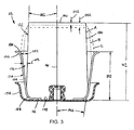
FIG. 3 is an enlarged side view, in partial cross-section, of the exemplary embodiment of a jounce bumper assembly inFIG. 2 . -
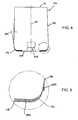
FIG. 4 is a side view of the exemplary embodiment of a jounce bumper inFIGS. 2 and3 . -
FIG. 5 is a greatly enlarged view of the portion of the jounce bumper shown asDetail 5 inFIG. 4 . -
FIG. 6 is a graphical representation of load versus deflection relationships for a jounce bumper assembly in accordance with the present invention relative to known jounce bumper constructions. - Turning now to the drawings wherein the showings are for the purpose of illustrating exemplary embodiments of the present invention and not for limiting the same,
FIG. 1 illustrates avehicle 100 having a sprung mass, such as avehicle body 102, for example, and an unsprung mass, such asaxles 104 and/orwheels 106, for example. A plurality of damping members, such asshock absorbers 108, for example, can be secured between the sprung and unsprung masses of the vehicle in a suitable manner. Additionally, a plurality ofgas spring assemblies 110 are disposed in a suitable manner between the sprung and unsprung masses of the vehicle, such asadjacent wheels 106 andshock absorbers 108 as shown inFIG. 1 , for example. Furthermore, one or more of the plurality of gas spring assemblies can include ajounce bumper assembly 112 operatively associated therewith. -
Vehicle 100 also includes a pressurizedgas supply system 114 that is in communication withgas spring assemblies 110 and that is operative to selectively supply pressurized gas thereto and exhaust pressurized gas therefrom.Gas supply system 114 includes a pressurized gas source, such as acompressor 116, and can optionally include a storage vessel, such as areservoir 118, for example, for receiving and storing pressurized gas, such as may be generated by the pressurized gas source.System 114 can further include a suitable exhaust, such as a muffler 120, for example, for venting pressurized gas from the system. -
Gas supply system 114 can be in communication with the gas spring assemblies in any suitable manner. For example,system 114 can include avalve assembly 122 or other suitable device or arrangement for selectively distributing pressurized gas to, from and/or between the pressurized gas source or sources, the exhaust and/or the gas spring assemblies. As shown in the exemplary embodiment inFIG. 1 ,compressor 116,reservoir 118 and muffler 120 are in fluid communication withvalve assembly 122 and can be selectively placed in fluid communication with one another therethrough. Additionally,assemblies 110 are in fluid communication withvalve assembly 122 viatransmission lines 124 and, thus, can be selectively placed in communication with the compressor, reservoir, muffler and/or one another therethrough. - In operation of the exemplary embodiment shown in
FIG. 1 ,valve assembly 122 can be selectively actuated to transfer pressurized gas from the compressor and/or reservoir to one or more of the gas spring assemblies. Additionally,valve assembly 122 can be selectively actuated to exhaust pressurized gas from one or more of the gas spring assemblies by way of muffler 120 or another suitable arrangement. It will be appreciated that the foregoing fluid supply system and operation thereof are merely exemplary and that any other suitable pressurized gas source, system and/or method of operation in accordance with the present novel concept could alternately be used. -
Vehicle 100 also includes a suspension control system 126 for selectively operating, adjusting or otherwise influencing or controlling the performance or one or more suspension system components, such asgas spring assemblies 110 and/or pressurizedgas supply system 114, for example. Suspension control system 126 includes an electronic control unit (ECU) 128 that is in communication with one or more components ofvalve assembly 122, such as through acommunication line 130, for example, for selective actuation and/or operation thereof.ECU 128 is also shown inFIG. 1 as being in communication with optional height sensing devices (not shown) that can be used in association withgas spring assemblies 110. It will be appreciated that such communications, if provided, can be implemented in any suitable manner, such as by way ofcommunication lines 132, for example. Additionally, it will be appreciated that any such optional height sensors or any other distance-determining devices, if provided, can be of any suitable type, kind, construction and/or configuration, such as mechanical linkage sensors, ultrasonic wave sensors or electromagnetic wave sensors, such as may operate using ultrasonic or electromagnetic waves WVS, for example. - It will be appreciated that
gas spring assemblies 110 can take any suitable form, configuration and/or construction. In the embodiment inFIG. 1 , eachassembly 110 is shown as being of a rolling lobe-type construction that includes opposing end members (not numbered inFIG. 1 ). A flexible wall (not numbered inFIG. 1 ) is suitably secured between the opposing end members and at least partially defines a spring chamber (not numbered inFIG. 1 ), which can be in fluid communication withtransmission line 124 in any suitable manner. In the exemplary embodiment shown, ajounce bumper assembly 112 is supported within the spring chamber on one of the end members of each gas spring assembly. It will be appreciated, however, that any other suitable arrangement, configuration and/or construction of gas spring assembly can alternately be used. - As illustrated in greater detail in
FIG. 2 ,gas spring assembly 110 includes a first end member, such as abead plate 134, for example, and a second end member, such as apiston 136, for example, that is spaced from the first end member. Aflexible wall 138 is disposed between the first and second end members and can be secured thereto in any suitable manner. In the exemplary embodiment shown inFIG. 2 , a firstopen end 140 offlexible wall 138 is secured onbead plate 134 using a roll crimped connection.Piston 136 includes abase wall 142, a side wall 144 extending from the base wall, and a somewhat dish-shaped upper end wall 146 opposite the base wall. Upper end wall 146 includes a bead-receivingsection 148 and a somewhat cup-shapedbottom wall section 150. - An opposing second
open end 152 offlexible wall 138 is received along bead-receivingportion 148. Anend closure 154 is received onpiston 136 withinbottom section 150 and engages secondopen end 152 offlexible wall 138.End closure 154 can be secured onpiston 136 in any suitable manner. For example, afastener 156 can extend through a passage (not numbered) in the piston and a corresponding opening (not numbered) in the end closure and engage a cooperative securement device, such as a threadednut 158, for example. Upon suitably securingend closure 154 onpiston 136, a substantially fluid-tight seal is formed between the end closure and the second open end of the flexible wall. As such, a substantially fluid-tight spring chamber 160 is defined byflexible wall 138 generally between the first and second end members. - The end members of
gas spring assembly 110 can be secured on suitable structural components, such as upper and lower vehicle components UVC and LVC, for example, in any suitable manner. In the exemplary embodiment shown inFIG. 2 ,bead plate 134 includes a first mounting stud 162 and second mountingstud 164 that can be secured on upper vehicle component UVC in a suitable manner, such as by using threaded nuts (not shown), for example. The spring chamber ofgas spring assembly 110 can be in communication with the pressurized gas supply system in any suitable manner. For example, second mountingstud 164 can include apassage 166 formed therethrough that is suitable for permitting fluid communication between a transmission line, such as transmission line 124 (FIG. 1 ) andspring chamber 160. -
Piston 136 is shown inFIG. 2 as being supported on lower vehicle component LVC and can be secured thereto in any suitable manner, such as by using afastener 168 to engage a corresponding securement feature on the piston, such as a threadedpassage 170, for example. It will be appreciated, however, that the above-discussed arrangement is merely exemplary and that any other suitable arrangement can alternately, or additionally, be used. - A
jounce bumper assembly 112 is shown inFIG. 2 as including ajounce bumper 172 and ajounce bumper retainer 174. In the exemplary embodiment shown inFIG. 2 ,jounce bumper assembly 112 is illustrated as being disposed along upper end wall 146 ofpiston 136. However, it will be appreciated that a jounce bumper assembly or any one or more components thereof can be disposed along either of the first or second end members or in another suitable arrangement, position, configuration and/or manner. InFIG. 2 ,jounce bumper assembly 112 is shown as being received withinend closure 154 and supported along a bottom wall 177 thereof. It will be appreciated that the jounce bumper assembly can be secured within the spring chamber in any suitable manner, such as, for example, by receivingjounce bumper 172 onnut 158 and thereby capturingretainer 174 between the jounce bumper and the end closure. Alternately, the bumper retainer and the jounce bumper can be separately secured on or along the same or different components. For example, the bumper retainer could be welded or otherwise secured on the end closure and the jounce bumper could be received on the nut as shown. As another example, the bumper retainer could be secured on or along one end member (e.g., bead plate 134) with the jounce bumper supported on or along the other end member (e.g., piston 136). - As shown in greater detail in
FIGS. 3-5 ,jounce bumper 172 ofjounce bumper assembly 112 includes a top orupper end wall 176, a bottom orlower end wall 178, and a central axis AX extending between the upper and lower end walls. As such,end walls side wall 180 extends between the upper and lower end walls and is disposed circumferentially around axis AX. As such,side wall 180 may be referred to as being laterally or radially outwardly spaced from axis AX. Though it will be appreciated that any other shape or configuration could alternately be used, endwalls -
Side wall 180 extends at an angle, indicated by dimension AG1 inFIG. 3 , relative to axis AX and, as such, generally establishes a generally frustoconical outer surface of the jounce bumper. While it will be appreciated that any suitable angle can be used, one exemplary range for angle AG1 is from about 1 degree to about 30 degrees. In the exemplary embodiment shown,side wall 180 is disposed at an angle AG1 of about 3 degrees from the axis. Additionally,jounce bumper 172 can be of any suitable height, such as is indicated by dimension H1, that would be suitable for the intended application, environment and/or conditions of use of the jounce bumper. One example of a suitable range of heights for the jounce bumper is from about 29 mm (1 inch) to about 305 mm (12 inches). Furthermore, in the embodiment shown inFIGS. 2-4 ,jounce bumper 172 also incudes a cavity 194 (FIG. 4 ) formed thereinto from alongbottom wall 178, which cavity is cooperable with a suitable device or component capable of securing the jounce bumper and/or other components of the jounce bumper assembly on or along the gas spring assembly. Notwithstanding the foregoing exemplary description, it will be appreciated that a jounce bumper of any suitable shape, configuration and/or construction can alternately be used. -
Jounce bumper assembly 112 also includesjounce bumper retainer 174 that includes abottom wall portion 182 and aside wall portion 184 extending frombottom wall portion 182 toward an opposingopen end 186. Aradiused corner 188 can optionally be formed betweenbottom wall portion 182 andside wall portion 184. Additionally, the side wall extends from alongbottom wall portion 182 towardopen end 186 and terminates at anupper end 190 ofside wall portion 184. Optionally, the upper end can be outwardly flared or include another suitable profile. -
Retainer 174 has an overall height, as indicated by dimension H2, that is shown inFIG. 3 as extending from approximatelybottom wall portion 182 to approximatelyupper end 190. In one preferred arrangement, retainer height H2 is established in relation to height H1 ofjounce bumper 172, such as by determining the retainer height as a percentage of the jounce bumper height, for example. One example of a suitable range is for retainer height H2 to be from about 20 percent to about 80 percent of jounce bumper height H1. One preferred range is for retainer height H2 to be from about 40 percent to about 70 percent of jounce bumper height H1. In the exemplary embodiment shown in the drawings, the retainer height is about 60 percent of the jounce bumper height. While a height determination based at least in part on a relative percentage calculation is discussed above, it will be appreciated that any other suitable relationship, determination and/or calculation could alternately be used. Additionally, as shown inFIG. 3 ,side wall portion 184 ofretainer 174 extends outwardly at an angle, generally indicated by dimension AG2, relative to axis AX and thereby forms a generally frustoconical inner surface. Though it will be appreciated that any suitable angle can be used, one example of a suitable range for angle AG2 is from about 5 degrees to about 50 degrees. In the exemplary embodiment shown in the drawings,side wall portion 184 extends at angle AG2 of about 15 degrees. - Due to the orientation of
bumper side wall 180 andretainer side wall 184 relative to one another, afree volume 192 is formed therebetween. It will be appreciated that the side walls of the jounce bumper and the bumper retainer can have any suitable shape, profile and/or configuration, and that the generally frustoconical side walls shown and described herein are merely exemplary and not intended to be limiting. Thus, it will be further appreciated that any such corresponding free volume can be of any size, shape and/or configuration as may be suitable for providing a jounce bumper assembly having desired performance characteristics for a given application, operation and/or use. - As shown in the exemplary embodiment in
FIGS. 2 and3 ,bumper side wall 180 forms a generally frustoconical outer surface of the jounce bumper. Additionally,retainer side wall 184 forms a generally frustoconical inner surface of the bumper retainer. Due to the shape and relative alignment of the inner and outer surfaces in the exemplary embodiment shown, the free volume formed therebetween has a somewhat pie or wedge-shaped annular cross section. As such, at a first position along axis AX, a distance or gap betweenbumper side wall 180 andretainer side wall 184 is generally indicated by dimension GP1. At a second position along axis AX, which second position is space from the first position in a direction oppositebottom end wall 178, a distance or gap between the bumper side wall and the retainer side wall is generally indicated by dimension GP2. In the exemplary embodiment shown, gap GP2 is greater than gap GP1 due to the somewhat pie-shaped annular cross section of the free volume. It will be appreciated, however, that any other suitable inner and outer surface profiles and/or angular alignments, resulting in any other corresponding annular cross sectional shapes and/or configurations, could alternately be used without departing from the scope and intent of the present invention. - Turning, briefly, to
FIGS. 4 and 5 ,jounce bumper 172 is shown in additional detail and can optionally includecavity 194 complimentary to nut 158 (FIGS. 2 and3 ) and suitable for receivably securing the jounce bumper thereon. Alternately, any other suitable mounting features and/or arrangements could be used. Additionally,jounce bumper 172 can include one or more features cooperable with the bumper retainer or other components. For example,jounce bumper 172 is shown as including arounded corner 196 that can be complimentary to optional rounded corner 188 (FIG. 3 ) of the bumper retainer. The jounce bumper can be freely supported within the bumper retainer under a no-load condition of the jounce bumper. Alternately, a minimal portion, shown as areas 198A inFIGS. 4 and 5 , of the jounce bumper could optionally be initially compressed after assembly with the bumper retainer. Additionally, or as a further alternative, while under a no-load condition of the jounce bumper, aportion 198B ofside wall 180 of the jounce bumper can also be optionally conformed to side wall portion 184 (FIG. 3 ) indicated by dimension AG2 inFIG. 4 . - In use, a jounce bumper assembly in accordance with the present invention can provide one or more desired performance characteristics. For example, a subject jounce bumper assembly can provide resistance to impact fatigue (i.e., provide the capability to withstand repeated impact loads) under the relatively high load conditions associated with heavy duty applications. A jounce bumper assembly according to the present novel concept can also provide the capability to tune the performance characteristics (e.g., spring rate and deflection) of the jounce bumper assembly by using differently shaped bumper and retainer side wall combinations to form different free volume configurations therebetween. The subject jounce bumper assembly can also achieve deflection, load carrying and other performance capabilities between those capabilities commonly provided by jounce bumpers formed from compliant materials (e.g., rubber and elastomeric foams) and those capabilities commonly associated with jounce bumpers formed from more rigid materials (e.g., fiber-reinforced and other high-strength plastics). Additionally, jounce bumper assemblies in accordance with the present invention can provide enhanced ride quality by permitting compliance during initial jounce travel of the suspension system while stiffening sufficiently during further jounce travel to minimize bump-through of road or other inputs. Furthermore, a jounce bumper assembly in accordance with the present invention can be capable of withstanding the loads associated with, and thereby functioning as a dock stabilizer for, the loading and unloading of the vehicle.
- To illustrate the use of a jounce bumper assembly in accordance with the present invention,
jounce bumper 172 ofjounce bumper assembly 112 is shown inFIG. 3 as being in a first, unloaded and undeflected condition, as indicated by reference character A. The jounce bumper can be axially deflected or displaced due to contact with any known components in any known configurations and/or arrangements, such as, for example, by having an opposing end member of a gas spring assembly, within which the jounce bumper assembly is disposed, contact the free end of the jounce bumper. The jounce bumper then being compressed in response to relative movement of associated structural members on or between which the end members of the gas spring assembly are disposed. As the free end (e.g., upper end wall 176) of the jounce bumper is displaced through a first axial distance, such as the exemplary distance represented by dimension DS1, for example, a corresponding lateral or radially outward displacement of the jounce bumper results, which radially outward displacement has a relation, at least in part, to the stress-strain properties of the material forming the jounce bumper. - In the exemplary representation in
FIG. 3 , a second condition of the jounce bumper is shown inFIG. 3 , as indicated by reference character B, which second condition is associated with the jounce bumper being displaced through first axial distance DS1 and resulting in the corresponding radially outward displacement. It will be recognized from the deformation of the jounce bumper represented by reference character B that the radially outward displacement of the jounce bumper, which is shown as being approximately equal to first gap GP1, at least partially fills or otherwise reduces the size offree volume 192. - Upon further displacement of the free end of the jounce bumper through a second axial distance, such as the exemplary distance represented by dimension DS2, for example, toward a third condition, which is indicated by reference character C, a further radially outward displacement of the jounce bumper occurs. This further radially outward displacement, which is shown in
FIG. 3 as being approximately equal to second gap GP2, further fills or otherwise reduces the size offree volume 192. It will also be appreciated that in the exemplary embodiment shown the degree of influence thatretainer side wall 184 will have on the jounce bumper will begin to diminish as the jounce bumper is further deflected in the axial direction. This is due, at least in part, to the reduced radially support provided by outwardly flaredend wall 190 ofbumper retainer 174. - As the jounce bumper is initially displaced from the free or unloaded condition represented by reference character A toward the condition represented by reference character B, it is expected that the load versus deflection relationship of the jounce bumper of a jounce bumper assembly in accordance with the present novel concept, such as
jounce bumper 172, for example, would initially approximately correspond to the load versus deflection relationship of known compliant bumpers, as indicated by reference character LDA of the load versus deflection curve inFIG. 6 . However, as the side wall of the jounce bumper increasingly engages the side wall of the bumper retainer, it is expected that the subject jounce bumper would begin to become increasingly stiff (i.e., to have less additional axial deflection at a given load) in comparison to a known jounce bumper that is formed from a similarly compliant material but which is unrestrained, as is represented inFIG. 6 by curve CJB. This increased stiffness characteristic of the jounce bumper assembly is represented along the load versus deflection curve inFIG. 6 by reference character LDB. Depending upon the specific arrangement, configuration and/or construction of the jounce bumper assembly, it will be understood that the influence of the retainer side wall in supporting the jounce bumper side wall may be reduced after a given amount of deflection has been reached. In such circumstances, the properties of the material forming the jounce bumper may become more prominent and could result in a somewhat reduced stiffness of the jounce bumper, as indicated by reference characters LDC of the load versus deflection curve inFIG. 6 . - It will be recognized from the load versus deflection curve in
FIG. 6 that a jounce bumper assembly in accordance with the present invention would be expected to provide an initially compliant performance characteristic that is similar to that of a known compliant jounce bumper. Upon further deflection, however, the subject jounce bumper assembly would be expected to provide substantially greater stiffness than such a known compliant jounce bumper yet remain more compliant than a known rigid jounce bumper. Additionally, it is expected that the subject jounce bumper assembly would be capable of withstanding loads comparable to those subjected to known rigid jounce bumpers, as indicated by the load versus deflection curve extending approximately as far along the LOAD axis as curve RJB, which is representative of a known rigid jounce bumper. - It should be understood that the deformations of the jounce bumper shown in
FIG. 3 are provided merely as illustrations for presenting the foregoing discussion and, further, it should be recognized that such deformations are not to scale and are not intended to represent actual deformation conditions, which will vary from embodiment-to-embodiment depending, for example, upon the construction, configuration and properties of the materials used as well as upon other possible factors. - It will be appreciated that the jounce bumper and bumper retainer of a jounce bumper assembly in accordance with the present invention can be formed from any materials or combination of materials that may be suitable for the intended application, environment and/or conditions of use thereof. In one exemplary embodiment,
jounce bumper 172 can be formed from one or more resilient materials, such as a rubber, a thermoplastic elastomer and/or an elastomeric foam, for example, alone or in combination with one another. Additionally,jounce bumper retainer 174 can be formed from one or more relatively rigid materials, such as a metal, a fiber (or otherwise) reinforced plastic and/or another high strength polymer (reinforced or unreinforced), for example, alone or in combination with one another. - As used herein with reference to certain elements, components and/or structures (e.g., "first end member" and "second end member"), numerical ordinals merely denote different singles of a plurality and do not imply any order or sequence unless specifically defined by the claim language. Additionally, the term "gas" is used herein to broadly refer to any gaseous or vaporous fluid. Most commonly, air is used as the working medium of suspension systems and the components thereof, such as those described herein. However, it will be understood that any suitable gaseous fluid could alternately be used.
- While the subject of the present invention has been described with reference to the foregoing embodiments and considerable emphasis has been placed herein on the structures and structural interrelationships between the component parts of the embodiments disclosed, it will be appreciated that other embodiments can be made and that many changes can be made in the embodiments illustrated and described without departing from the principles of the present invention. Obviously, modifications and alterations will occur to others upon reading and understanding the preceding detailed description. Accordingly, it is to be distinctly understood that the foregoing descriptive matter is to be interpreted merely as illustrative of the present invention and not as a limitation. As such, it is intended that the subject of the present invention be construed as including all such modifications and alterations insofar as they come within the scope of the appended claims.
Claims (14)
- A gas spring assembly for use in forming an associated suspension system between an associated sprung mass (102) and an associated unsprung mass (104) of an associated vehicle (100), said gas spring assembly (110) comprising:a first end member (134) capable of being operatively connected to one of the associated sprung and unsprung masses (102, 104);a second end member (136) capable of being operatively connected to the other of the associated sprung and unsprung masses (102, 104);a flexible wall (138) including first and second open ends (140, 152) and disposed between said first and second end members (134, 136) to at least partially define a gas chamber (160) therebetween, said first open end (140) being secured on said first end member (134) and said second open end (152) being disposed along said second end member (136);an end closure (154) including a closure bottom wall (177) and a closure side wall extending from said closure bottom wall (177), said end closure (154) positioned such that said closure bottom wall (177) is disposed toward said second end member (136) and said closure side wall is in abutting engagement with said second open end (152) of said flexible wall (138), said end closure (154) being secured along said second end member (136) such that a substantially fluid-tight connection is formed along said second open end (152) of said flexible wall (138); anda resilient bumper (172) including a bumper top wall (176), a bumper bottom wall (178), a bumper side wall (180) extending therebetween and having a central axis (AX) extending between said bumper top and bottom walls (176, 178), said resilient bumper (172) supported on said second end member (136) such that at least a portion of said bumper side wall (180) is disposed radially inwardly of said retainer side wall (184) forming a free volume (192) therebetween, said free volume (192) capable of permitting said retainer side wall (184) to engage said bumper side wall (180) under axial deflection of said resilient bumper (172) to thereby restrict radially outward deflection of said resilient bumper (172),characterized by
a bumper retainer (174) including a retainer bottom wall (182) and a retainer side wall (184) extending from said retainer bottom wall (182), said bumper retainer (174) supported on said second end member (136) within said end closure (154) such that said retainer bottom wall (182) is disposed adjacent said closure bottom wall (177) and said retainer side wall (184) is disposed radially inwardly from said closure side wall;
wherein said resilient bumper (172) is received within said bumper retainer (174) such that said bumper bottom wall (178) is disposed along said closure bottom wall (177) of said end closure (154). - A gas spring assembly according to claim 1, wherein said resilient bumper (172) has a bumper height (H1) and said bumper retainer (174) has a retainer height (H2) of from about 20 percent to about 80 percent of said bumper height (H1).
- A gas spring assembly according to claim 1, wherein said retainer side wall (184) and said bumper side wall (180) are disposed at a non-zero angle relative to one another to thereby at least partially define said free volume (192) with at least one of said retainer side wall (184) and said bumper side wall (180) at least partially forming a frustoconical surface.
- A gas spring assembly according to claim 3, wherein said bumper retainer (174) has a central axis (AX) and said retainer side wall (184) is disposed at an angle (AG2) of from about 5 degrees to about 50 degrees relative to said central axis (AX).
- A gas spring assembly according to claim 3, wherein said resilient bumper (172) has a central axis (AX) and said bumper side wall (180) is disposed at an angle (AG1) of from about 1 degree to about 15 degrees relative to said central axis (AX).
- A jounce bumper assembly capable of use within a spring chamber (160) of a gas spring assembly (110) that includes an end member (136) that is secured to a flexible wall (138) by an end closure (154), said jounce bumper assembly (112) comprising:a resilient jounce bumper (172) including an axis (AX), a first bumper end wall (178), an opposing second bumper end wall (176), a bumper side wall (180) extending between said first and second bumper end walls (178, 176) and said jounce bumper (172) having a bumper height (H1); and,a bumper retainer (174) including an axis (AX), a retainer bottom wall (182) extending approximately transverse to said axis (AX) and a retainer side wall (184) extending from said retainer bottom wall (182) toward an opposing open end (186), said bumper retainer (174) having a retainer height (H2) of from about 20 percent to about 80 percent of said bumper height (H1);said jounce bumper (172) approximately coaxially received within said bumper retainer (174) such that said first bumper end wall (178) is disposed in abutting engagement with at least a portion of said retainer bottom wall (182) and said second bumper end wall (176) projects outwardly from said open end (186) of said bumper retainer (174) such that said jounce bumper (172) can be supported on the end closure (154) within said bumper retainer (174) with said first bumper end wall (178) disposed along the end closure (154) and thereby captures said bumper retainer (174) between said jounce bumper (172) and the end closure (154);said bumper side wall (180) and said retainer side wall (184) extending at a non-zero angle relative to one another such that a free volume (192) is formed therebetween that has a first radial gap (GP1) between said bumper side wall (180) and said retainer side wall (184) at a first axial position and a second radial gap (GP2) between said bumper side wall (180) and said retainer side wall (184) at a second axial position spaced from said first axial position.
- A jounce bumper assembly according to claim 6, wherein said jounce bumper (172) is formed from a resilient material selected from the group consisting of rubber and thermoplastic elastomer.
- A jounce bumper assembly according to claim 6 or 7, wherein said bumper retainer (174) is formed from a substantially rigid material selected from the group consisting of metal, fiber reinforced plastic and high-strength unreinforced polymer.
- A jounce bumper assembly according to any one of claims 6-8, wherein said bumper retainer (174) has a retainer height (H2) of from about 40 percent to about 70 percent of said bumper height (H1).
- A jounce bumper assembly according to any one of claims 6-9, wherein said first and second end walls (178, 176) of said jounce bumper (172) are substantially planar.
- A jounce bumper assembly according to any one of claims 6-10, wherein said bumper side wall (180) and said retainer side wall (184) each respectively form a frustoconical surface along at least a portion of said jounce bumper (172) and said bumper retainer (174).
- A jounce bumper assembly according to any one of claims 6-11, wherein said second axial position is spaced from said first axial position in a direction extending away from said first bumper end wall (178) and said second radial gap (GP2) is greater than said first radial gap (GP1).
- A method of utilizing a jounce bumper assembly (112) disposed on an end closure (154) of a gas spring assembly (110) supported between displaceably supported structural members, said method comprising:a) providing a jounce bumper (172) including an axis (AX), a first bumper end wall (178), a second bumper end wall (176) spaced from said first bumper end wall (178), and a side wall (180) extending between said first and second bumper end walls (178, 176);b) providing a bumper retainer (174) including an axis (AX), a retainer bottom wall (182) and a retainer side wall (184) extending from said retainer bottom wall (182) toward an opposing open end (186);c) supporting said jounce bumper (172) and said bumper retainer (174) along the end closure (154) between the structural members with said bumper retainer (174) in approximately coaxial alignment with said jounce bumper (172), and such that said first bumper end wall (178) is disposed along the end closure (154) and thereby captures said bumper retainer (174) between said jounce bumper (172) and the end closure (154);d) compressing said jounce bumper (172) in response to relative displacement of the structural members and thereby axially inwardly and radially outwardly deflecting said jounce bumper (172); and,e) abuttingly engaging said bumper side wall (180) and said retainer side wall (184) and thereby at least partially restricting radially outward deflection of at least a portion of said jounce bumper (172) due to said axially inward deflection in c).
- A method according to claim 13, wherein providing said jounce bumper (172) includes providing a jounce bumper (172) formed from a resilient material selected from the group consisting of rubber and thermoplastic elastomer, and said method further comprises releasing said compression in c) such that said bumper side wall (180) and said retainer side wall (184) at least partially disengage one another.
Applications Claiming Priority (2)
| Application Number | Priority Date | Filing Date | Title |
|---|---|---|---|
| US11/820,432 US7896320B2 (en) | 2007-06-19 | 2007-06-19 | Jounce bumper assembly and gas spring assembly including same |
| PCT/US2008/065893 WO2008157058A1 (en) | 2007-06-19 | 2008-06-05 | Jounce bumper assembly and gas spring assembly including same |
Publications (3)
| Publication Number | Publication Date |
|---|---|
| EP2170634A1 EP2170634A1 (en) | 2010-04-07 |
| EP2170634A4 EP2170634A4 (en) | 2011-08-17 |
| EP2170634B1 true EP2170634B1 (en) | 2014-07-02 |
Family
ID=40135665
Family Applications (1)
| Application Number | Title | Priority Date | Filing Date |
|---|---|---|---|
| EP08770174.4A Not-in-force EP2170634B1 (en) | 2007-06-19 | 2008-06-05 | Jounce bumper assembly and gas spring assembly including same |
Country Status (3)
| Country | Link |
|---|---|
| US (1) | US7896320B2 (en) |
| EP (1) | EP2170634B1 (en) |
| WO (1) | WO2008157058A1 (en) |
Families Citing this family (13)
| Publication number | Priority date | Publication date | Assignee | Title |
|---|---|---|---|---|
| EP2158415A1 (en) * | 2007-05-18 | 2010-03-03 | BFS Diversified Products, LLC | Gas spring assembly |
| BR112012003525A2 (en) * | 2009-08-19 | 2017-09-26 | Aktas Hava Suspansiyon Sistemleri Sanayi Ve Ticaret Anonim Sirketi | air spring stop, production method and air suspension system |
| US8864113B2 (en) | 2009-10-14 | 2014-10-21 | Firestone Industrial Products Company, Llc | End member, gas spring assembly and method |
| EP2563607B1 (en) * | 2010-04-26 | 2016-07-27 | Firestone Industrial Products Company, LLC | Gas spring assembly and method of assembling same |
| DE112013000742T5 (en) * | 2012-01-29 | 2014-10-16 | Firestone Industrial Products Company, Llc | Bump stop, end element, gas spring assembly and assembly process |
| JP5920015B2 (en) * | 2012-05-21 | 2016-05-18 | 住友電気工業株式会社 | Air spring for moving body and moving body vehicle using the same |
| JP5920014B2 (en) * | 2012-05-21 | 2016-05-18 | 住友電気工業株式会社 | Air spring and mobile vehicle using the same |
| US9556922B2 (en) * | 2012-08-29 | 2017-01-31 | Firestone Industrial Products Company, Llc | End members and gas spring assemblies including same |
| WO2015073811A1 (en) * | 2013-11-15 | 2015-05-21 | Firestone Industrial Products Company, Llc | End closures as well as gas spring assemblies and methods of assembly including same |
| USD746183S1 (en) | 2014-07-09 | 2015-12-29 | Firestone Industrial Products Company, Llc | Gas spring end member |
| CN105465259A (en) * | 2015-12-25 | 2016-04-06 | 中电投工程研究检测评定中心 | Method for widening application range of bellow type air spring |
| US10690209B2 (en) * | 2018-08-02 | 2020-06-23 | Contitech Luftfedersysteme Gmbh | Press-on composite bumper to composite piston |
| EP4710008A1 (en) | 2023-05-10 | 2026-03-18 | Firestone Industrial Products Company, LLC | Jounce bumper assemblies and gas spring assemblies including same |
Family Cites Families (32)
| Publication number | Priority date | Publication date | Assignee | Title |
|---|---|---|---|---|
| GB1189295A (en) * | 1966-10-13 | 1970-04-22 | Metalastik Ltd | Improvements in or relating to Fluid Springs |
| US3565456A (en) * | 1968-12-16 | 1971-02-23 | Motor Coach Ind Ltd | Rear suspension for vehicles |
| GB1248025A (en) * | 1970-05-06 | 1971-09-29 | Orszagos Gumiipari Vall | A rolling bellows type air spring |
| US3752462A (en) * | 1971-05-14 | 1973-08-14 | Clevite Corp | Elastomeric spring and frictional damping shock absorber |
| HU174666B (en) * | 1977-06-30 | 1980-03-28 | Autoipari Kutato Intezet | Amortiseur having air spring and telescopic damper of damping limited in direct ratio to loading particularly for motor vehicles |
| US4398704A (en) * | 1979-07-16 | 1983-08-16 | General Motors Corporation | Vehicle pneumatic suspension system with dead band adjustment |
| US4342264A (en) * | 1980-02-28 | 1982-08-03 | Bi-Modal Corporation | Convertible rail-highway semi-trailer fluid suspension |
| JPS5865342A (en) * | 1981-10-09 | 1983-04-19 | Nissan Motor Co Ltd | Elastically supporting construction |
| DE3147231C1 (en) * | 1981-11-28 | 1983-03-31 | Bergische Achsenfabrik Fr. Kotz & Söhne, 5276 Wiehl | Air spring |
| IT1150508B (en) * | 1982-04-01 | 1986-12-10 | Pirelli | PNEUMATIC BELL SPRING |
| US4506910A (en) * | 1982-09-21 | 1985-03-26 | Granning Suspensions, Inc. | Automotive vehicle suspension |
| JPS60179538A (en) * | 1984-02-23 | 1985-09-13 | Bridgestone Corp | Gas charged spring |
| US4787606A (en) * | 1987-06-17 | 1988-11-29 | The Firestone Tire & Rubber Company | Beadless air spring |
| JP2581701Y2 (en) * | 1989-11-16 | 1998-09-24 | フオルクスウアーゲン・アクチエンゲゼルシヤフト | Damping support |
| JPH044332A (en) * | 1990-04-21 | 1992-01-08 | Tokico Ltd | air spring |
| US5201500A (en) * | 1991-02-26 | 1993-04-13 | Bridgestone/Firestone, Inc. | Snap-on bumper for air spring |
| US5382006A (en) * | 1993-09-29 | 1995-01-17 | The Goodyear Tire & Rubber Company | Airspring piston and airspring assembly |
| US5535994A (en) * | 1993-11-30 | 1996-07-16 | The Goodyear Tire & Rubber Company | Composite air spring piston |
| JP2881544B2 (en) | 1994-02-28 | 1999-04-12 | 日野自動車工業株式会社 | Air spring device |
| DE19505026C2 (en) * | 1995-02-15 | 1996-12-12 | Fichtel & Sachs Ag | Self-pumping air spring |
| KR19990012553A (en) | 1997-07-30 | 1999-02-25 | 양재신 | Integral air spring and shock absorber |
| US6070861A (en) * | 1998-03-12 | 2000-06-06 | Bridgestone/Firestone, Inc | Bumper extension for use with a bumper on an air spring |
| US5934652A (en) * | 1998-05-28 | 1999-08-10 | The Goodyear Tire & Rubber Company | Air spring bumper and method of mounting |
| US6113081A (en) * | 1998-06-30 | 2000-09-05 | Bridgestone/Firestone, Inc. | Snap-on bumper for air spring |
| US6109598A (en) * | 1999-06-29 | 2000-08-29 | Bridgestone/Firestone, Inc. | Air spring bumper utilizing a combination of materials |
| US6234460B1 (en) * | 1999-08-23 | 2001-05-22 | The Goodyear Tire & Rubber Company | Push-on air spring bumper |
| KR100391367B1 (en) | 2000-12-19 | 2003-07-12 | 기아자동차주식회사 | Air spring for vehicle |
| JP4194300B2 (en) | 2002-05-30 | 2008-12-10 | 日野自動車株式会社 | Air spring device |
| US6857624B2 (en) * | 2002-11-27 | 2005-02-22 | The Goodyear Tire & Rubber Company | Tunable spring rate and energy storage spring body |
| KR20050092516A (en) | 2004-03-16 | 2005-09-22 | 현대자동차주식회사 | System of air spring including shock absorber |
| US7500659B2 (en) * | 2005-04-07 | 2009-03-10 | Bfs Diversified Products, Llc | Air spring assembly and method |
| US7347414B2 (en) * | 2006-06-30 | 2008-03-25 | Ford Global Technologies, Llc | Integrated vehicle shock absorber mount and jounce bumper |
-
2007
- 2007-06-19 US US11/820,432 patent/US7896320B2/en not_active Expired - Fee Related
-
2008
- 2008-06-05 WO PCT/US2008/065893 patent/WO2008157058A1/en not_active Ceased
- 2008-06-05 EP EP08770174.4A patent/EP2170634B1/en not_active Not-in-force
Also Published As
| Publication number | Publication date |
|---|---|
| US7896320B2 (en) | 2011-03-01 |
| WO2008157058A1 (en) | 2008-12-24 |
| US20080315474A1 (en) | 2008-12-25 |
| EP2170634A4 (en) | 2011-08-17 |
| EP2170634A1 (en) | 2010-04-07 |
Similar Documents
| Publication | Publication Date | Title |
|---|---|---|
| US7896320B2 (en) | Jounce bumper assembly and gas spring assembly including same | |
| EP2296921B1 (en) | Gas spring piston and assembly | |
| US20170241504A1 (en) | Damping air spring with dynamically variable orifice | |
| US20180093542A1 (en) | End member assemblies as well as gas spring assemblies, suspension systems and methods | |
| AU2015296548B2 (en) | Suspension systems and methods of operating same | |
| US10449819B2 (en) | Damping convoluted air spring | |
| WO2020033247A1 (en) | Damping air spring with variable piston volume | |
| EP2343463B1 (en) | Rigid jounce bumper and gas spring assembly including same | |
| EP2236852A2 (en) | Gas spring assembly and suspension system including same | |
| US10830306B2 (en) | Jounce bumper assemblies as well as gas spring assemblies including same | |
| AU2024210429B2 (en) | End member assemblies and gas spring assemblies including same | |
| EP4710008A1 (en) | Jounce bumper assemblies and gas spring assemblies including same | |
| WO2024155918A1 (en) | End member assemblies and gas spring assemblies including same | |
| WO2024155922A1 (en) | End member assemblies and gas spring assemblies including same |
Legal Events
| Date | Code | Title | Description |
|---|---|---|---|
| PUAI | Public reference made under article 153(3) epc to a published international application that has entered the european phase |
Free format text: ORIGINAL CODE: 0009012 |
|
| 17P | Request for examination filed |
Effective date: 20100118 |
|
| AK | Designated contracting states |
Kind code of ref document: A1 Designated state(s): AT BE BG CH CY CZ DE DK EE ES FI FR GB GR HR HU IE IS IT LI LT LU LV MC MT NL NO PL PT RO SE SI SK TR |
|
| AX | Request for extension of the european patent |
Extension state: AL BA MK RS |
|
| DAX | Request for extension of the european patent (deleted) | ||
| A4 | Supplementary search report drawn up and despatched |
Effective date: 20110720 |
|
| RIC1 | Information provided on ipc code assigned before grant |
Ipc: F16F 1/36 20060101ALI20110714BHEP Ipc: B60G 11/22 20060101AFI20110714BHEP Ipc: F16F 1/371 20060101ALI20110714BHEP |
|
| 17Q | First examination report despatched |
Effective date: 20130924 |
|
| REG | Reference to a national code |
Ref country code: DE Ref legal event code: R079 Ref document number: 602008033108 Country of ref document: DE Free format text: PREVIOUS MAIN CLASS: B60G0011220000 Ipc: B60G0011620000 |
|
| GRAP | Despatch of communication of intention to grant a patent |
Free format text: ORIGINAL CODE: EPIDOSNIGR1 |
|
| RIC1 | Information provided on ipc code assigned before grant |
Ipc: F16F 1/36 20060101ALI20140203BHEP Ipc: B60G 11/62 20060101AFI20140203BHEP Ipc: F16F 9/05 20060101ALI20140203BHEP Ipc: F16F 1/371 20060101ALI20140203BHEP |
|
| INTG | Intention to grant announced |
Effective date: 20140228 |
|
| GRAS | Grant fee paid |
Free format text: ORIGINAL CODE: EPIDOSNIGR3 |
|
| GRAA | (expected) grant |
Free format text: ORIGINAL CODE: 0009210 |
|
| AK | Designated contracting states |
Kind code of ref document: B1 Designated state(s): AT BE BG CH CY CZ DE DK EE ES FI FR GB GR HR HU IE IS IT LI LT LU LV MC MT NL NO PL PT RO SE SI SK TR |
|
| REG | Reference to a national code |
Ref country code: GB Ref legal event code: FG4D |
|
| REG | Reference to a national code |
Ref country code: AT Ref legal event code: REF Ref document number: 675707 Country of ref document: AT Kind code of ref document: T Effective date: 20140715 Ref country code: CH Ref legal event code: EP |
|
| REG | Reference to a national code |
Ref country code: IE Ref legal event code: FG4D |
|
| REG | Reference to a national code |
Ref country code: DE Ref legal event code: R096 Ref document number: 602008033108 Country of ref document: DE Effective date: 20140814 |
|
| REG | Reference to a national code |
Ref country code: AT Ref legal event code: MK05 Ref document number: 675707 Country of ref document: AT Kind code of ref document: T Effective date: 20140702 |
|
| REG | Reference to a national code |
Ref country code: NL Ref legal event code: VDEP Effective date: 20140702 |
|
| REG | Reference to a national code |
Ref country code: LT Ref legal event code: MG4D |
|
| PG25 | Lapsed in a contracting state [announced via postgrant information from national office to epo] |
Ref country code: FI Free format text: LAPSE BECAUSE OF FAILURE TO SUBMIT A TRANSLATION OF THE DESCRIPTION OR TO PAY THE FEE WITHIN THE PRESCRIBED TIME-LIMIT Effective date: 20140702 Ref country code: PT Free format text: LAPSE BECAUSE OF FAILURE TO SUBMIT A TRANSLATION OF THE DESCRIPTION OR TO PAY THE FEE WITHIN THE PRESCRIBED TIME-LIMIT Effective date: 20141103 Ref country code: GR Free format text: LAPSE BECAUSE OF FAILURE TO SUBMIT A TRANSLATION OF THE DESCRIPTION OR TO PAY THE FEE WITHIN THE PRESCRIBED TIME-LIMIT Effective date: 20141003 Ref country code: ES Free format text: LAPSE BECAUSE OF FAILURE TO SUBMIT A TRANSLATION OF THE DESCRIPTION OR TO PAY THE FEE WITHIN THE PRESCRIBED TIME-LIMIT Effective date: 20140702 Ref country code: LT Free format text: LAPSE BECAUSE OF FAILURE TO SUBMIT A TRANSLATION OF THE DESCRIPTION OR TO PAY THE FEE WITHIN THE PRESCRIBED TIME-LIMIT Effective date: 20140702 Ref country code: NO Free format text: LAPSE BECAUSE OF FAILURE TO SUBMIT A TRANSLATION OF THE DESCRIPTION OR TO PAY THE FEE WITHIN THE PRESCRIBED TIME-LIMIT Effective date: 20141002 Ref country code: BG Free format text: LAPSE BECAUSE OF FAILURE TO SUBMIT A TRANSLATION OF THE DESCRIPTION OR TO PAY THE FEE WITHIN THE PRESCRIBED TIME-LIMIT Effective date: 20141002 Ref country code: SE Free format text: LAPSE BECAUSE OF FAILURE TO SUBMIT A TRANSLATION OF THE DESCRIPTION OR TO PAY THE FEE WITHIN THE PRESCRIBED TIME-LIMIT Effective date: 20140702 Ref country code: CZ Free format text: LAPSE BECAUSE OF FAILURE TO SUBMIT A TRANSLATION OF THE DESCRIPTION OR TO PAY THE FEE WITHIN THE PRESCRIBED TIME-LIMIT Effective date: 20140702 |
|
| PG25 | Lapsed in a contracting state [announced via postgrant information from national office to epo] |
Ref country code: IS Free format text: LAPSE BECAUSE OF FAILURE TO SUBMIT A TRANSLATION OF THE DESCRIPTION OR TO PAY THE FEE WITHIN THE PRESCRIBED TIME-LIMIT Effective date: 20141102 Ref country code: CY Free format text: LAPSE BECAUSE OF FAILURE TO SUBMIT A TRANSLATION OF THE DESCRIPTION OR TO PAY THE FEE WITHIN THE PRESCRIBED TIME-LIMIT Effective date: 20140702 Ref country code: AT Free format text: LAPSE BECAUSE OF FAILURE TO SUBMIT A TRANSLATION OF THE DESCRIPTION OR TO PAY THE FEE WITHIN THE PRESCRIBED TIME-LIMIT Effective date: 20140702 Ref country code: NL Free format text: LAPSE BECAUSE OF FAILURE TO SUBMIT A TRANSLATION OF THE DESCRIPTION OR TO PAY THE FEE WITHIN THE PRESCRIBED TIME-LIMIT Effective date: 20140702 Ref country code: HR Free format text: LAPSE BECAUSE OF FAILURE TO SUBMIT A TRANSLATION OF THE DESCRIPTION OR TO PAY THE FEE WITHIN THE PRESCRIBED TIME-LIMIT Effective date: 20140702 Ref country code: LV Free format text: LAPSE BECAUSE OF FAILURE TO SUBMIT A TRANSLATION OF THE DESCRIPTION OR TO PAY THE FEE WITHIN THE PRESCRIBED TIME-LIMIT Effective date: 20140702 Ref country code: PL Free format text: LAPSE BECAUSE OF FAILURE TO SUBMIT A TRANSLATION OF THE DESCRIPTION OR TO PAY THE FEE WITHIN THE PRESCRIBED TIME-LIMIT Effective date: 20140702 |
|
| REG | Reference to a national code |
Ref country code: DE Ref legal event code: R097 Ref document number: 602008033108 Country of ref document: DE |
|
| PG25 | Lapsed in a contracting state [announced via postgrant information from national office to epo] |
Ref country code: SK Free format text: LAPSE BECAUSE OF FAILURE TO SUBMIT A TRANSLATION OF THE DESCRIPTION OR TO PAY THE FEE WITHIN THE PRESCRIBED TIME-LIMIT Effective date: 20140702 Ref country code: IT Free format text: LAPSE BECAUSE OF FAILURE TO SUBMIT A TRANSLATION OF THE DESCRIPTION OR TO PAY THE FEE WITHIN THE PRESCRIBED TIME-LIMIT Effective date: 20140702 Ref country code: RO Free format text: LAPSE BECAUSE OF FAILURE TO SUBMIT A TRANSLATION OF THE DESCRIPTION OR TO PAY THE FEE WITHIN THE PRESCRIBED TIME-LIMIT Effective date: 20140702 Ref country code: EE Free format text: LAPSE BECAUSE OF FAILURE TO SUBMIT A TRANSLATION OF THE DESCRIPTION OR TO PAY THE FEE WITHIN THE PRESCRIBED TIME-LIMIT Effective date: 20140702 Ref country code: DK Free format text: LAPSE BECAUSE OF FAILURE TO SUBMIT A TRANSLATION OF THE DESCRIPTION OR TO PAY THE FEE WITHIN THE PRESCRIBED TIME-LIMIT Effective date: 20140702 |
|
| PLBE | No opposition filed within time limit |
Free format text: ORIGINAL CODE: 0009261 |
|
| STAA | Information on the status of an ep patent application or granted ep patent |
Free format text: STATUS: NO OPPOSITION FILED WITHIN TIME LIMIT |
|
| 26N | No opposition filed |
Effective date: 20150407 |
|
| PG25 | Lapsed in a contracting state [announced via postgrant information from national office to epo] |
Ref country code: SI Free format text: LAPSE BECAUSE OF FAILURE TO SUBMIT A TRANSLATION OF THE DESCRIPTION OR TO PAY THE FEE WITHIN THE PRESCRIBED TIME-LIMIT Effective date: 20140702 |
|
| PG25 | Lapsed in a contracting state [announced via postgrant information from national office to epo] |
Ref country code: MC Free format text: LAPSE BECAUSE OF FAILURE TO SUBMIT A TRANSLATION OF THE DESCRIPTION OR TO PAY THE FEE WITHIN THE PRESCRIBED TIME-LIMIT Effective date: 20140702 |
|
| REG | Reference to a national code |
Ref country code: CH Ref legal event code: PL |
|
| GBPC | Gb: european patent ceased through non-payment of renewal fee |
Effective date: 20150605 |
|
| PG25 | Lapsed in a contracting state [announced via postgrant information from national office to epo] |
Ref country code: LU Free format text: LAPSE BECAUSE OF FAILURE TO SUBMIT A TRANSLATION OF THE DESCRIPTION OR TO PAY THE FEE WITHIN THE PRESCRIBED TIME-LIMIT Effective date: 20150605 |
|
| REG | Reference to a national code |
Ref country code: IE Ref legal event code: MM4A |
|
| REG | Reference to a national code |
Ref country code: FR Ref legal event code: ST Effective date: 20160229 |
|
| PG25 | Lapsed in a contracting state [announced via postgrant information from national office to epo] |
Ref country code: CH Free format text: LAPSE BECAUSE OF NON-PAYMENT OF DUE FEES Effective date: 20150630 Ref country code: GB Free format text: LAPSE BECAUSE OF NON-PAYMENT OF DUE FEES Effective date: 20150605 Ref country code: LI Free format text: LAPSE BECAUSE OF NON-PAYMENT OF DUE FEES Effective date: 20150630 Ref country code: IE Free format text: LAPSE BECAUSE OF NON-PAYMENT OF DUE FEES Effective date: 20150605 |
|
| PG25 | Lapsed in a contracting state [announced via postgrant information from national office to epo] |
Ref country code: FR Free format text: LAPSE BECAUSE OF NON-PAYMENT OF DUE FEES Effective date: 20150630 |
|
| PG25 | Lapsed in a contracting state [announced via postgrant information from national office to epo] |
Ref country code: BE Free format text: LAPSE BECAUSE OF FAILURE TO SUBMIT A TRANSLATION OF THE DESCRIPTION OR TO PAY THE FEE WITHIN THE PRESCRIBED TIME-LIMIT Effective date: 20140702 |
|
| PGFP | Annual fee paid to national office [announced via postgrant information from national office to epo] |
Ref country code: DE Payment date: 20160629 Year of fee payment: 9 |
|
| PG25 | Lapsed in a contracting state [announced via postgrant information from national office to epo] |
Ref country code: MT Free format text: LAPSE BECAUSE OF FAILURE TO SUBMIT A TRANSLATION OF THE DESCRIPTION OR TO PAY THE FEE WITHIN THE PRESCRIBED TIME-LIMIT Effective date: 20140702 |
|
| PG25 | Lapsed in a contracting state [announced via postgrant information from national office to epo] |
Ref country code: HU Free format text: LAPSE BECAUSE OF FAILURE TO SUBMIT A TRANSLATION OF THE DESCRIPTION OR TO PAY THE FEE WITHIN THE PRESCRIBED TIME-LIMIT; INVALID AB INITIO Effective date: 20080605 |
|
| PG25 | Lapsed in a contracting state [announced via postgrant information from national office to epo] |
Ref country code: TR Free format text: LAPSE BECAUSE OF FAILURE TO SUBMIT A TRANSLATION OF THE DESCRIPTION OR TO PAY THE FEE WITHIN THE PRESCRIBED TIME-LIMIT Effective date: 20140702 |
|
| REG | Reference to a national code |
Ref country code: DE Ref legal event code: R119 Ref document number: 602008033108 Country of ref document: DE |
|
| PG25 | Lapsed in a contracting state [announced via postgrant information from national office to epo] |
Ref country code: DE Free format text: LAPSE BECAUSE OF NON-PAYMENT OF DUE FEES Effective date: 20180103 |