EP2170615B1 - Colour print cartridge - Google Patents
Colour print cartridge Download PDFInfo
- Publication number
- EP2170615B1 EP2170615B1 EP08794766A EP08794766A EP2170615B1 EP 2170615 B1 EP2170615 B1 EP 2170615B1 EP 08794766 A EP08794766 A EP 08794766A EP 08794766 A EP08794766 A EP 08794766A EP 2170615 B1 EP2170615 B1 EP 2170615B1
- Authority
- EP
- European Patent Office
- Prior art keywords
- compartment
- ink
- block
- passageway
- base
- Prior art date
- Legal status (The legal status is an assumption and is not a legal conclusion. Google has not performed a legal analysis and makes no representation as to the accuracy of the status listed.)
- Not-in-force
Links
- 239000000976 ink Substances 0.000 claims abstract description 64
- 239000006261 foam material Substances 0.000 claims abstract description 12
- 230000002209 hydrophobic effect Effects 0.000 claims abstract description 12
- 239000012530 fluid Substances 0.000 claims abstract description 7
- 230000006835 compression Effects 0.000 claims abstract description 4
- 238000007906 compression Methods 0.000 claims abstract description 4
- 238000004519 manufacturing process Methods 0.000 claims description 2
- 239000006260 foam Substances 0.000 abstract description 24
- 210000004894 snout Anatomy 0.000 description 5
- 238000005192 partition Methods 0.000 description 2
- 230000007547 defect Effects 0.000 description 1
- 230000014509 gene expression Effects 0.000 description 1
- 238000002347 injection Methods 0.000 description 1
- 239000007924 injection Substances 0.000 description 1
- 238000000034 method Methods 0.000 description 1
- 229920003023 plastic Polymers 0.000 description 1
- 239000004033 plastic Substances 0.000 description 1
- 229920002635 polyurethane Polymers 0.000 description 1
- 239000004814 polyurethane Substances 0.000 description 1
Images



Classifications
-
- B—PERFORMING OPERATIONS; TRANSPORTING
- B41—PRINTING; LINING MACHINES; TYPEWRITERS; STAMPS
- B41J—TYPEWRITERS; SELECTIVE PRINTING MECHANISMS, i.e. MECHANISMS PRINTING OTHERWISE THAN FROM A FORME; CORRECTION OF TYPOGRAPHICAL ERRORS
- B41J2/00—Typewriters or selective printing mechanisms characterised by the printing or marking process for which they are designed
- B41J2/005—Typewriters or selective printing mechanisms characterised by the printing or marking process for which they are designed characterised by bringing liquid or particles selectively into contact with a printing material
- B41J2/01—Ink jet
- B41J2/17—Ink jet characterised by ink handling
- B41J2/175—Ink supply systems ; Circuit parts therefor
- B41J2/17503—Ink cartridges
- B41J2/17513—Inner structure
Definitions
- the present invention relates to a print cartridge.
- US 6,851,800 discloses a colour print cartridge for an desktop ink jet printer.
- the cartridge comprises a housing 100 whose interior is divided by partitions 150, 152 into three compartments (or ink reservoirs) 106, 108 and 110, each for containing a differently coloured ink.
- compartments 106 and 108 are located side-by-side across the rear of the housing while compartment 110 extends across the full width of the front of the housing (in the present specification top, bottom, front, rear and like expressions refer to the orientation of the cartridge shown in the drawings).
- a print head die 160 is attached to the base of the print cartridge housing 100.
- the print head 160 includes slots which align with outlet ports 120, 130 and 140 in the base of the housing 100.
- the bottom of the compartment 106 includes an exit port 170 that opens into a cavity 172 of the housing 100 to provide fluid communication between the interior of the compartment 106 and the print head 160 via the outlet port 130.
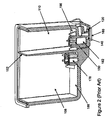
- the compartment 110 is in fluid communication with the print head 160 via a cavity 182 and the outlet port 140, Figure 2
- the compartment 110 is in fluid communication with the print head 160 via a cavity (not shown but similar to cavities 172, 182) and the outlet port 120.
- a duct (or standpipe) 174 located within the compartment 106 is connected to the exit port 170, Figure 1 .
- the entrance to the standpipe 174 is above the bottom of the compartment 106.
- the standpipe 174 constitutes the only exit from the compartment 106 to the print head 160.
- Similar standpipes 178, 180 for compartments 108, 110 respectively can be seen in Figure 2 , each having an entrance above the bottom of the respective compartment and constituting the only exit from the compartment to the print head 160.
- Respective filters are fitted over the entrance to each standpipe.
- a respective foam block (not shown in Figures 1 and 2 ) is pre-compressed and push fitted into each compartment 106, 108, 110.
- Each block is generally rectangular and conforms closely to the side walls of the respective compartment.
- the bottom surface of each block sits on top of a respective standpipe filter and defines a free space (herein referred to as a snout region) laterally adjacent each standpipe at the bottom of each compartment.
- a snout region a free space laterally adjacent each standpipe at the bottom of each compartment.
- the snout regions for compartments 108, 110 are indicated by numerals 188, 190 respectively.
- a lid (not shown in Figures 1 and 2 but similar to the lid 166 shown in the embodiment of Figure 5 ) is fitted to the top of the housing 100. Within the lid 166 at least one hole 167 is formed in register with each standpipe. The cartridge is subjected to a vacuum with air being drawn downwardly through the compartments from the base of the housing through their respective standpipes. Respective ink dispensing needles (not shown in Figures 1 and 2 ) are introduced through the holes in the lid into the body of the foam blocks filling the compartments.
- the foam employed is polyurethane which is strongly hydrophobic when dry.
- Ink dispensed by the needles is therefore forced into the foam and the ink expands outwardly and downwardly within the foam until the ink meets an outside surface of the foam block.
- the ink will first meet the underside of the foam block above the standpipe, at which time the ink will tend to be drawn into and fill the standpipe and associated cavity before spreading further into the foam. Thereafter, the ink settles and spreads out in the compartment and, if enough ink is injected, will ultimately meet the internal sidewalls of the compartment as well as fill the snout region.
- the needles are withdrawn, and the cartridge is removed from the vacuum.
- the holes in the lid may be covered, for example with a label, although they should not be sealed so that they can act as air vents to allow ink to be drawn downwardly from the compartments during use of the cartridge.
- a disadvantage of this cartridge is that several foam blocks are required and each of these must be placed in a respective compartment prior to filling the cartridge. While the blocks for compartments 106 and 108 may be the same size, the block for compartment 110 may be a different shape leading to a relatively high part count for fabricating the cartridge.
- EP771662A2 discloses a print cartridge with several foam blocks for containing several inks.
- the invention enables relatively low capacity cartridges to be produced with a minimal part count and with a simplified manufacturing process.
- a method for making a print cartridge is also claimed in claim 7.
- the number of foam to plastic wall interfaces is smaller and hence reduces the probability of reliability defects that occur at these boundaries such as foam curling.
- the compression of the foam and the effective capillary radius is the same across all ink chambers, thus reducing backpressure variation and its impact on print quality and ink efficiency.
- the principle difference from the prior art is that the entrances to the standpipes 174, 178, 180 are at substantially the same height within the housing 100 and the partitions 150, 152 have been replaced by low walls 150a, 152a extending upwardly from the bottom of the compartment to substantially the same height as the entrances to the standpipes.
- This structure defines a single interior compartment 250 within the housing 100 rather than, as before, three separate compartments 106, 108 and 1-10, and all three standpipes have entrances in this single compartment 250.
- the cartridge now comprises only a single block 252 of hydrophobic foam material.
- the block 252 is inserted under compression into the compartment 250 and is dimensioned to substantially fill the compartment 250 above the entrances to the standpipes 174, 178 and 180, the lower surface of the block being immediately above and preferably in contact with the entrances to the standpipes.
- a free space or snout region 186, 188, 190 is located laterally adjacent to each standpipe 174, 178, 180 respectively.
- Respective ink dispensing needles 192 are introduced through the holes 167 in the lid into the body of the foam block 252. Each needle terminates in the foam block centrally above a respective standpipe entrance. Ink is injected into the block 252 through the needles 192, each needle dispensing a differently coloured ink.
- the ink dispensed by each needle is forced into the foam block and expands outwardly and downwardly within the foam until the ink meets the underside of the foam block above a respective standpipe, at which time the ink will tend to be drawn into and fill the standpipe and associated snout region.
- the amount of ink injected by each needle 192 is precisely controlled to ensure that the differently coloured regions of ink injected by the needles do not meet in the block but remain as separate, non-contiguous regions - see, for example, the regions of ink 194, 196 dispensed into the foam block above the standpipes 174, 180.
- the regions of ink 194, 196 dispensed into the foam block above the standpipes 174, 180.
Landscapes
- Ink Jet (AREA)
- Automatic Analysis And Handling Materials Therefor (AREA)
Abstract
Description
- The present invention relates to a print cartridge.
-
US 6,851,800 discloses a colour print cartridge for an desktop ink jet printer. As shown inFigure 1 , the cartridge comprises ahousing 100 whose interior is divided bypartitions Figure 1 ,compartments compartment 110 extends across the full width of the front of the housing (in the present specification top, bottom, front, rear and like expressions refer to the orientation of the cartridge shown in the drawings). - A
print head die 160 is attached to the base of theprint cartridge housing 100. Theprint head 160 includes slots which align withoutlet ports housing 100. The bottom of thecompartment 106 includes anexit port 170 that opens into acavity 172 of thehousing 100 to provide fluid communication between the interior of thecompartment 106 and theprint head 160 via theoutlet port 130. Similarly, thecompartment 110 is in fluid communication with theprint head 160 via acavity 182 and theoutlet port 140,Figure 2 , and thecompartment 110 is in fluid communication with theprint head 160 via a cavity (not shown but similar tocavities 172, 182) and theoutlet port 120. - A duct (or standpipe) 174 located within the
compartment 106 is connected to theexit port 170,Figure 1 . The entrance to thestandpipe 174 is above the bottom of thecompartment 106. Thestandpipe 174 constitutes the only exit from thecompartment 106 to theprint head 160.Similar standpipes compartments Figure 2 , each having an entrance above the bottom of the respective compartment and constituting the only exit from the compartment to theprint head 160. Respective filters (not shown) are fitted over the entrance to each standpipe. - In order to charge the cartridge with ink, a respective foam block (not shown in
Figures 1 and2 ) is pre-compressed and push fitted into eachcompartment Figure 2 the snout regions forcompartments numerals - Before charging the cartridge, a lid (not shown in
Figures 1 and2 but similar to thelid 166 shown in the embodiment ofFigure 5 ) is fitted to the top of thehousing 100. Within thelid 166 at least onehole 167 is formed in register with each standpipe. The cartridge is subjected to a vacuum with air being drawn downwardly through the compartments from the base of the housing through their respective standpipes. Respective ink dispensing needles (not shown inFigures 1 and2 ) are introduced through the holes in the lid into the body of the foam blocks filling the compartments. Typically, the foam employed is polyurethane which is strongly hydrophobic when dry. Ink dispensed by the needles is therefore forced into the foam and the ink expands outwardly and downwardly within the foam until the ink meets an outside surface of the foam block. Typically, the ink will first meet the underside of the foam block above the standpipe, at which time the ink will tend to be drawn into and fill the standpipe and associated cavity before spreading further into the foam. Thereafter, the ink settles and spreads out in the compartment and, if enough ink is injected, will ultimately meet the internal sidewalls of the compartment as well as fill the snout region. - Once the ink has been dispensed, the needles are withdrawn, and the cartridge is removed from the vacuum. The holes in the lid may be covered, for example with a label, although they should not be sealed so that they can act as air vents to allow ink to be drawn downwardly from the compartments during use of the cartridge.
- Recently, there has been a demand to supply ink cartridges of a given format (i.e. exterior size and shape) with varying levels of ink capacity. So, for example, more intense printer users may wish to purchase high capacity cartridges for their printer containing, for example, 8ml of ink per compartment, whereas low use users may wish to purchase low capacity cartridges containing, for example, 1ml of ink per compartment for the same model of printer. Heretofore, colour print cartridges with different ink capacities have been manufactured simply by injecting different quantities of ink into each
compartment - A disadvantage of this cartridge is that several foam blocks are required and each of these must be placed in a respective compartment prior to filling the cartridge. While the blocks for
compartments compartment 110 may be a different shape leading to a relatively high part count for fabricating the cartridge. -
EP771662A2 - According to the present invention there is provided a print cartridge as claimed in claim 1.
- The invention enables relatively low capacity cartridges to be produced with a minimal part count and with a simplified manufacturing process. A method for making a print cartridge is also claimed in claim 7.
- Also, the number of foam to plastic wall interfaces is smaller and hence reduces the probability of reliability defects that occur at these boundaries such as foam curling.
- Furthermore, the compression of the foam and the effective capillary radius is the same across all ink chambers, thus reducing backpressure variation and its impact on print quality and ink efficiency.
- An embodiment of the invention will now be described, by way of example, with reference to the accompanying drawings, in which:
-
Figure 1 is a perspective view of a conventional print cartridge; -
Figure 2 is a perspective view of a front-to-rear section of the print cartridge ofFigure 1 ; -
Figure 3 is plan view of a housing for a low capacity print cartridge according to an embodiment of the invention; -
Figure 4 is top perspective view of the print cartridge housing ofFigure 3 ; -
Figure 5 is a vertical cross-section of the low capacity print cartridge according to the embodiment of the invention, taken on line V-V ofFigure 3 . - In the drawings the same reference numerals are used for the same or equivalent parts in the prior art and the embodiment. Only the differences between the embodiment and prior art will be described.
- Referring now to the embodiment of the invention shown in
Figures 3 to 5 , the principle difference from the prior art is that the entrances to thestandpipes housing 100 and thepartitions low walls interior compartment 250 within thehousing 100 rather than, as before, threeseparate compartments single compartment 250. - In addition, the cartridge now comprises only a
single block 252 of hydrophobic foam material. Theblock 252 is inserted under compression into thecompartment 250 and is dimensioned to substantially fill thecompartment 250 above the entrances to thestandpipes snout region standpipe - To charge the cartridge with ink, the cartridge is first subjected to a vacuum with air being drawn downwardly through the
compartment 250 from the base of the housing through the three standpipes. Respective ink dispensing needles 192 (only the needles for thestandpipes Figure 5 ) are introduced through theholes 167 in the lid into the body of thefoam block 252. Each needle terminates in the foam block centrally above a respective standpipe entrance. Ink is injected into theblock 252 through theneedles 192, each needle dispensing a differently coloured ink. The ink dispensed by each needle is forced into the foam block and expands outwardly and downwardly within the foam until the ink meets the underside of the foam block above a respective standpipe, at which time the ink will tend to be drawn into and fill the standpipe and associated snout region. - However, the amount of ink injected by each
needle 192 is precisely controlled to ensure that the differently coloured regions of ink injected by the needles do not meet in the block but remain as separate, non-contiguous regions - see, for example, the regions ofink standpipes - Although a respective single, centrally positioned
needle 192 is used in the above embodiment to inject the ink into a region of the foam block above each standpipe, it is possible to use two injection needles, offset from the centre of the standpipe, to inject each region of ink. The use of two needles to dispense a single region of ink above a respective standpipe is described in our co-pendingUK application no. 0708268.8 filed 30 April 2007 - The invention is not limited to the embodiment described herein but can be amended or modified without departing from the scope of the present invention as claimed.
Claims (7)
- A print cartridge comprising a plurality of printing inks and an ink housing(100) containing a block of hydrophobic foam material (252), the bock of hydrophobic foam material (252) containing the plurality of printing inks, wherein each printing ink has a different colour and occupies a region (194;196) of the block of hydrophobic foam material (252), the region (194; 196) that each printing ink occupies being non-contiguous with the region (196; 194) occupied by another printing ink..
- A print cartridge as claimed in claim 1, wherein the ink housing (100) has a top and a base and an interior compartment (250), the print cartridge further comprising a print head mounted at the base of the housing (100) in fluid communication with the interior of the compartment (250) via a plurality of passageways in the base each having an entrance in the compartment (250), wherein the block of hydrophobic foam material (252) is compressed in the compartment (250) immediately above the passageway entrances, and wherein the plurality of different printing inks each fills a respective passageway and a respective region of the block of hydrophobic foam material (252) above the passageway.
- A print cartridge as claimed in claim 2, wherein each passageway has an entrance above the bottom of the compartment (250), the entrances being partitioned off from one another by low walls (150a; 152a) extending upwardly from the bottom of the compartment (250), wherein the compressed block of hydrophobic foam material (252) above the passageway entrances leaves a free space laterally adjacent to each passageway, and wherein the plurality different printing inks further fill the free space adjacent to each passageway.
- A print cartridge as claimed in claim 2 or 3, wherein the compartment (250) is closed by a cover at the top of the housing, the cover having at least one air vent.
- A print cartridge as claimed in any of claims 2 to 4, wherein the entrances to the passageways are all located at substantially the same height above the base of the ink housing (100).
- A print cartridge as claimed in any of the preceding claims, wherein the ink housing (100) has a top and a base and an interior compartment (250), the ink housing (100) further having a plurality of passageways in the base each having an entrance in the compartment (250) to allow fluid communication between the interior of the compartment (250) and a print head mounted at the base of the ink housing (100).
- A method of making a print cartridge comprising providing an ink housing (100) having a top and a base and an interior compartment (250), the ink housing (100) further having a plurality of passageways in the base each having an entrance in the compartment (250) to allow fluid communication between the interior of the compartment (250) and a print head mounted at the base of the ink housing (100), inserting a block of hydrophobic foam material (252) under compression into the compartment (250) immediately above the passageway entrances, and injecting a plurality of different printing inks, each printing ink having a different colour, into the block of foam material (252) such that each printing ink fills a respective passageway and a respective region of the block of foam material (252) above the passageway, the different printing inks occupying non-contiguous regions within the block of hydrophobic foam material (252).
Applications Claiming Priority (2)
| Application Number | Priority Date | Filing Date | Title |
|---|---|---|---|
| GB0714565A GB2451280A (en) | 2007-07-26 | 2007-07-26 | Colour print cartridge having a single block of hydrophobic foam material |
| PCT/US2008/009062 WO2009017676A1 (en) | 2007-07-26 | 2008-07-25 | Colour print cartridge |
Publications (3)
| Publication Number | Publication Date |
|---|---|
| EP2170615A1 EP2170615A1 (en) | 2010-04-07 |
| EP2170615A4 EP2170615A4 (en) | 2010-07-21 |
| EP2170615B1 true EP2170615B1 (en) | 2012-03-14 |
Family
ID=38512898
Family Applications (1)
| Application Number | Title | Priority Date | Filing Date |
|---|---|---|---|
| EP08794766A Not-in-force EP2170615B1 (en) | 2007-07-26 | 2008-07-25 | Colour print cartridge |
Country Status (6)
| Country | Link |
|---|---|
| US (1) | US8602539B2 (en) |
| EP (1) | EP2170615B1 (en) |
| AT (1) | ATE549167T1 (en) |
| GB (1) | GB2451280A (en) |
| TW (1) | TWI342832B (en) |
| WO (1) | WO2009017676A1 (en) |
Families Citing this family (4)
| Publication number | Priority date | Publication date | Assignee | Title |
|---|---|---|---|---|
| WO2019013753A1 (en) * | 2017-07-10 | 2019-01-17 | Hewlett-Packard Development Company, L.P. | Printing fluid cartridge |
| JP7110038B2 (en) | 2018-09-06 | 2022-08-01 | キヤノン株式会社 | Liquid storage container and liquid ejection device |
| US11897270B2 (en) | 2018-11-20 | 2024-02-13 | Hewlett-Packard Development Company, L.P. | Fluid supply valve |
| CN113015627B (en) | 2018-11-20 | 2023-02-03 | 惠普发展公司,有限责任合伙企业 | Printer fluid port |
Family Cites Families (22)
| Publication number | Priority date | Publication date | Assignee | Title |
|---|---|---|---|---|
| US4771295B1 (en) * | 1986-07-01 | 1995-08-01 | Hewlett Packard Co | Thermal ink jet pen body construction having improved ink storage and feed capability |
| US6015210A (en) * | 1993-11-29 | 2000-01-18 | Canon Kabushiki Kaisha | Ink container with two ink absorbing members for controlling ink flow to a recording head |
| US5467117A (en) * | 1994-02-23 | 1995-11-14 | Hewlett-Packard Company | Addition of alcohol to prewet solutions to enhance and accelerate wetting to hydrophobic foams for application to ink-jet pens |
| US5576750A (en) * | 1994-10-11 | 1996-11-19 | Lexmark International, Inc. | Reliable connecting pathways for a three-color ink-jet cartridge |
| US5661510A (en) * | 1994-11-22 | 1997-08-26 | Lexmark International, Inc. | Ink-jet cartridge venting |
| JP3315589B2 (en) * | 1995-06-21 | 2002-08-19 | キヤノン株式会社 | Ink tank and recording apparatus provided with the same |
| EP0770489B1 (en) * | 1995-10-26 | 1999-05-26 | Hewlett-Packard Company | Ink containment system for an ink-jet pen |
| JP3226803B2 (en) * | 1995-11-02 | 2001-11-05 | キヤノン株式会社 | Ink absorber for injecting ink, ink tank using the absorber, inkjet cartridge, inkjet recording apparatus, and method of manufacturing ink tank |
| JPH10235890A (en) * | 1996-06-25 | 1998-09-08 | Seiko Epson Corp | ink cartridge |
| GB2316037B (en) * | 1996-08-02 | 2000-03-22 | Seiko Epson Corp | Ink cartridge and a printing device using the ink cartridge |
| US5926195A (en) * | 1996-11-22 | 1999-07-20 | Lexmark International Inc. | Ink jet printhead cartridge |
| US6095643A (en) * | 1998-05-07 | 2000-08-01 | Lexmark International, Inc. | Refillable disposable inkjet cartridge with foam-filled and free ink reservoirs |
| US6260961B1 (en) * | 2000-03-02 | 2001-07-17 | Hewlett-Packard Company | Unitary one-piece body structure for ink-jet cartridge |
| US6585361B1 (en) * | 2000-10-06 | 2003-07-01 | Seiko Epson Corporation | Multiple-chamber cartridge with varying porous member compression |
| TW553838B (en) * | 2001-05-02 | 2003-09-21 | Int United Technology Co Ltd | Ink container which can improve ink flow |
| US7033010B2 (en) * | 2003-09-16 | 2006-04-25 | Hewlett-Packard Development, L.P. | Ink delivery apparatus with collapsible ink chamber and method of use |
| US7290871B2 (en) * | 2004-06-30 | 2007-11-06 | Lexmark International, Inc. | Ink cartridge with pocketed lid |
| US7448742B2 (en) * | 2004-09-14 | 2008-11-11 | Shaw Raymond D | Reusable cartridge for inkjet printer |
| WO2006132427A1 (en) * | 2005-06-10 | 2006-12-14 | Canon Kabushiki Kaisha | Ink jet ink, method of producing ink jet ink, ink jet recording method, ink cartridge, and cyan ink |
| US20070035596A1 (en) * | 2005-08-10 | 2007-02-15 | Lexmark International, Inc. | Ink jet cartridge |
| US7399074B2 (en) * | 2005-09-30 | 2008-07-15 | Lexmark International, Inc. | Ink tank for a printhead |
| CN101291813A (en) * | 2005-10-14 | 2008-10-22 | 惠普开发有限公司 | ink tank |
-
2007
- 2007-07-26 GB GB0714565A patent/GB2451280A/en not_active Withdrawn
-
2008
- 2008-06-26 TW TW097123869A patent/TWI342832B/en not_active IP Right Cessation
- 2008-07-25 AT AT08794766T patent/ATE549167T1/en active
- 2008-07-25 US US12/663,567 patent/US8602539B2/en not_active Expired - Fee Related
- 2008-07-25 WO PCT/US2008/009062 patent/WO2009017676A1/en not_active Ceased
- 2008-07-25 EP EP08794766A patent/EP2170615B1/en not_active Not-in-force
Also Published As
| Publication number | Publication date |
|---|---|
| EP2170615A4 (en) | 2010-07-21 |
| US20100177150A1 (en) | 2010-07-15 |
| GB0714565D0 (en) | 2007-09-05 |
| US8602539B2 (en) | 2013-12-10 |
| EP2170615A1 (en) | 2010-04-07 |
| GB2451280A (en) | 2009-01-28 |
| TW200914281A (en) | 2009-04-01 |
| ATE549167T1 (en) | 2012-03-15 |
| WO2009017676A1 (en) | 2009-02-05 |
| TWI342832B (en) | 2011-06-01 |
Similar Documents
| Publication | Publication Date | Title |
|---|---|---|
| EP1114725B1 (en) | ink-jet pen with two-part lid and techniques for filling | |
| EP1258362B1 (en) | Ink cartridge and method of ink injection thereinto | |
| US7699452B2 (en) | Ink cartridge and method of ink injection thereinto | |
| EP0956959B1 (en) | Ink container with dual negative pressure producing members urged together and method of manufacturing the same | |
| US6010212A (en) | Ink cartridge | |
| US8602539B2 (en) | Colour print cartridge | |
| US6276785B1 (en) | Ink-supplied printer head and ink container | |
| CN101356059A (en) | Printer Cartridges and Ink Refill Methods | |
| US5821964A (en) | Cartridge for supplying liquid to a print head | |
| US8449088B2 (en) | Making print cartridge using two hollow needles | |
| KR100571776B1 (en) | Ink cartridge | |
| EP2152518B1 (en) | Print cartridge | |
| CN105291593A (en) | Box | |
| EP0770489B1 (en) | Ink containment system for an ink-jet pen | |
| CN220129792U (en) | Printer ink box structure and printer | |
| EP0887189A2 (en) | Ink-jet print cartridge body | |
| CN210148932U (en) | Universal ink box | |
| EP1885562B1 (en) | Ink supply | |
| KR200361310Y1 (en) | An ink cartridge for use in ink-jet printer | |
| US20050088496A1 (en) | Ink refilling cap | |
| MXPA97008747A (en) | Container for liquid that goes to eyecta | |
| KR20060020052A (en) | Inkjet Cartridge and Manufacturing Method Thereof | |
| TH18380A (en) | Ink cartridge, nozzles and printer cartridges | |
| EP2197689A2 (en) | Filling an ink pen | |
| HK1079158A (en) | Liquid container, method of manufacturing the container, package of the container, ink jet head cartridge in which the container and a recording head are made integral with each other, and liquid discharge recording apparatus |
Legal Events
| Date | Code | Title | Description |
|---|---|---|---|
| PUAI | Public reference made under article 153(3) epc to a published international application that has entered the european phase |
Free format text: ORIGINAL CODE: 0009012 |
|
| 17P | Request for examination filed |
Effective date: 20100113 |
|
| AK | Designated contracting states |
Kind code of ref document: A1 Designated state(s): AT BE BG CH CY CZ DE DK EE ES FI FR GB GR HR HU IE IS IT LI LT LU LV MC MT NL NO PL PT RO SE SI SK TR |
|
| AX | Request for extension of the european patent |
Extension state: AL BA MK RS |
|
| A4 | Supplementary search report drawn up and despatched |
Effective date: 20100623 |
|
| DAX | Request for extension of the european patent (deleted) | ||
| GRAP | Despatch of communication of intention to grant a patent |
Free format text: ORIGINAL CODE: EPIDOSNIGR1 |
|
| GRAS | Grant fee paid |
Free format text: ORIGINAL CODE: EPIDOSNIGR3 |
|
| GRAA | (expected) grant |
Free format text: ORIGINAL CODE: 0009210 |
|
| GRAL | Information related to payment of fee for publishing/printing deleted |
Free format text: ORIGINAL CODE: EPIDOSDIGR3 |
|
| GRAS | Grant fee paid |
Free format text: ORIGINAL CODE: EPIDOSNIGR3 |
|
| AK | Designated contracting states |
Kind code of ref document: B1 Designated state(s): AT BE BG CH CY CZ DE DK EE ES FI FR GB GR HR HU IE IS IT LI LT LU LV MC MT NL NO PL PT RO SE SI SK TR |
|
| REG | Reference to a national code |
Ref country code: GB Ref legal event code: FG4D |
|
| REG | Reference to a national code |
Ref country code: AT Ref legal event code: REF Ref document number: 549167 Country of ref document: AT Kind code of ref document: T Effective date: 20120315 Ref country code: CH Ref legal event code: EP |
|
| REG | Reference to a national code |
Ref country code: NL Ref legal event code: T3 |
|
| REG | Reference to a national code |
Ref country code: IE Ref legal event code: FG4D |
|
| REG | Reference to a national code |
Ref country code: DE Ref legal event code: R096 Ref document number: 602008014149 Country of ref document: DE Effective date: 20120510 |
|
| PG25 | Lapsed in a contracting state [announced via postgrant information from national office to epo] |
Ref country code: HR Free format text: LAPSE BECAUSE OF FAILURE TO SUBMIT A TRANSLATION OF THE DESCRIPTION OR TO PAY THE FEE WITHIN THE PRESCRIBED TIME-LIMIT Effective date: 20120314 Ref country code: LT Free format text: LAPSE BECAUSE OF FAILURE TO SUBMIT A TRANSLATION OF THE DESCRIPTION OR TO PAY THE FEE WITHIN THE PRESCRIBED TIME-LIMIT Effective date: 20120314 Ref country code: NO Free format text: LAPSE BECAUSE OF FAILURE TO SUBMIT A TRANSLATION OF THE DESCRIPTION OR TO PAY THE FEE WITHIN THE PRESCRIBED TIME-LIMIT Effective date: 20120614 |
|
| LTIE | Lt: invalidation of european patent or patent extension |
Effective date: 20120314 |
|
| PG25 | Lapsed in a contracting state [announced via postgrant information from national office to epo] |
Ref country code: LV Free format text: LAPSE BECAUSE OF FAILURE TO SUBMIT A TRANSLATION OF THE DESCRIPTION OR TO PAY THE FEE WITHIN THE PRESCRIBED TIME-LIMIT Effective date: 20120314 Ref country code: FI Free format text: LAPSE BECAUSE OF FAILURE TO SUBMIT A TRANSLATION OF THE DESCRIPTION OR TO PAY THE FEE WITHIN THE PRESCRIBED TIME-LIMIT Effective date: 20120314 Ref country code: GR Free format text: LAPSE BECAUSE OF FAILURE TO SUBMIT A TRANSLATION OF THE DESCRIPTION OR TO PAY THE FEE WITHIN THE PRESCRIBED TIME-LIMIT Effective date: 20120615 |
|
| REG | Reference to a national code |
Ref country code: AT Ref legal event code: MK05 Ref document number: 549167 Country of ref document: AT Kind code of ref document: T Effective date: 20120314 |
|
| PG25 | Lapsed in a contracting state [announced via postgrant information from national office to epo] |
Ref country code: CY Free format text: LAPSE BECAUSE OF FAILURE TO SUBMIT A TRANSLATION OF THE DESCRIPTION OR TO PAY THE FEE WITHIN THE PRESCRIBED TIME-LIMIT Effective date: 20120314 |
|
| PG25 | Lapsed in a contracting state [announced via postgrant information from national office to epo] |
Ref country code: RO Free format text: LAPSE BECAUSE OF FAILURE TO SUBMIT A TRANSLATION OF THE DESCRIPTION OR TO PAY THE FEE WITHIN THE PRESCRIBED TIME-LIMIT Effective date: 20120314 Ref country code: CZ Free format text: LAPSE BECAUSE OF FAILURE TO SUBMIT A TRANSLATION OF THE DESCRIPTION OR TO PAY THE FEE WITHIN THE PRESCRIBED TIME-LIMIT Effective date: 20120314 Ref country code: SE Free format text: LAPSE BECAUSE OF FAILURE TO SUBMIT A TRANSLATION OF THE DESCRIPTION OR TO PAY THE FEE WITHIN THE PRESCRIBED TIME-LIMIT Effective date: 20120314 Ref country code: IS Free format text: LAPSE BECAUSE OF FAILURE TO SUBMIT A TRANSLATION OF THE DESCRIPTION OR TO PAY THE FEE WITHIN THE PRESCRIBED TIME-LIMIT Effective date: 20120714 Ref country code: BE Free format text: LAPSE BECAUSE OF FAILURE TO SUBMIT A TRANSLATION OF THE DESCRIPTION OR TO PAY THE FEE WITHIN THE PRESCRIBED TIME-LIMIT Effective date: 20120314 Ref country code: PL Free format text: LAPSE BECAUSE OF FAILURE TO SUBMIT A TRANSLATION OF THE DESCRIPTION OR TO PAY THE FEE WITHIN THE PRESCRIBED TIME-LIMIT Effective date: 20120314 Ref country code: EE Free format text: LAPSE BECAUSE OF FAILURE TO SUBMIT A TRANSLATION OF THE DESCRIPTION OR TO PAY THE FEE WITHIN THE PRESCRIBED TIME-LIMIT Effective date: 20120314 Ref country code: SI Free format text: LAPSE BECAUSE OF FAILURE TO SUBMIT A TRANSLATION OF THE DESCRIPTION OR TO PAY THE FEE WITHIN THE PRESCRIBED TIME-LIMIT Effective date: 20120314 |
|
| PG25 | Lapsed in a contracting state [announced via postgrant information from national office to epo] |
Ref country code: SK Free format text: LAPSE BECAUSE OF FAILURE TO SUBMIT A TRANSLATION OF THE DESCRIPTION OR TO PAY THE FEE WITHIN THE PRESCRIBED TIME-LIMIT Effective date: 20120314 Ref country code: PT Free format text: LAPSE BECAUSE OF FAILURE TO SUBMIT A TRANSLATION OF THE DESCRIPTION OR TO PAY THE FEE WITHIN THE PRESCRIBED TIME-LIMIT Effective date: 20120716 |
|
| PLBE | No opposition filed within time limit |
Free format text: ORIGINAL CODE: 0009261 |
|
| STAA | Information on the status of an ep patent application or granted ep patent |
Free format text: STATUS: NO OPPOSITION FILED WITHIN TIME LIMIT |
|
| PG25 | Lapsed in a contracting state [announced via postgrant information from national office to epo] |
Ref country code: AT Free format text: LAPSE BECAUSE OF FAILURE TO SUBMIT A TRANSLATION OF THE DESCRIPTION OR TO PAY THE FEE WITHIN THE PRESCRIBED TIME-LIMIT Effective date: 20120314 Ref country code: DK Free format text: LAPSE BECAUSE OF FAILURE TO SUBMIT A TRANSLATION OF THE DESCRIPTION OR TO PAY THE FEE WITHIN THE PRESCRIBED TIME-LIMIT Effective date: 20120314 |
|
| 26N | No opposition filed |
Effective date: 20121217 |
|
| PG25 | Lapsed in a contracting state [announced via postgrant information from national office to epo] |
Ref country code: MC Free format text: LAPSE BECAUSE OF NON-PAYMENT OF DUE FEES Effective date: 20120731 Ref country code: IT Free format text: LAPSE BECAUSE OF FAILURE TO SUBMIT A TRANSLATION OF THE DESCRIPTION OR TO PAY THE FEE WITHIN THE PRESCRIBED TIME-LIMIT Effective date: 20120314 |
|
| REG | Reference to a national code |
Ref country code: CH Ref legal event code: PL |
|
| REG | Reference to a national code |
Ref country code: DE Ref legal event code: R097 Ref document number: 602008014149 Country of ref document: DE Effective date: 20121217 |
|
| PG25 | Lapsed in a contracting state [announced via postgrant information from national office to epo] |
Ref country code: ES Free format text: LAPSE BECAUSE OF FAILURE TO SUBMIT A TRANSLATION OF THE DESCRIPTION OR TO PAY THE FEE WITHIN THE PRESCRIBED TIME-LIMIT Effective date: 20120625 Ref country code: LI Free format text: LAPSE BECAUSE OF NON-PAYMENT OF DUE FEES Effective date: 20120731 Ref country code: CH Free format text: LAPSE BECAUSE OF NON-PAYMENT OF DUE FEES Effective date: 20120731 |
|
| REG | Reference to a national code |
Ref country code: IE Ref legal event code: MM4A |
|
| PG25 | Lapsed in a contracting state [announced via postgrant information from national office to epo] |
Ref country code: BG Free format text: LAPSE BECAUSE OF FAILURE TO SUBMIT A TRANSLATION OF THE DESCRIPTION OR TO PAY THE FEE WITHIN THE PRESCRIBED TIME-LIMIT Effective date: 20120614 Ref country code: MT Free format text: LAPSE BECAUSE OF FAILURE TO SUBMIT A TRANSLATION OF THE DESCRIPTION OR TO PAY THE FEE WITHIN THE PRESCRIBED TIME-LIMIT Effective date: 20120314 Ref country code: IE Free format text: LAPSE BECAUSE OF NON-PAYMENT OF DUE FEES Effective date: 20120725 |
|
| PG25 | Lapsed in a contracting state [announced via postgrant information from national office to epo] |
Ref country code: TR Free format text: LAPSE BECAUSE OF FAILURE TO SUBMIT A TRANSLATION OF THE DESCRIPTION OR TO PAY THE FEE WITHIN THE PRESCRIBED TIME-LIMIT Effective date: 20120314 |
|
| PG25 | Lapsed in a contracting state [announced via postgrant information from national office to epo] |
Ref country code: LU Free format text: LAPSE BECAUSE OF NON-PAYMENT OF DUE FEES Effective date: 20120725 |
|
| PG25 | Lapsed in a contracting state [announced via postgrant information from national office to epo] |
Ref country code: HU Free format text: LAPSE BECAUSE OF FAILURE TO SUBMIT A TRANSLATION OF THE DESCRIPTION OR TO PAY THE FEE WITHIN THE PRESCRIBED TIME-LIMIT Effective date: 20080725 |
|
| PGFP | Annual fee paid to national office [announced via postgrant information from national office to epo] |
Ref country code: NL Payment date: 20150622 Year of fee payment: 8 |
|
| REG | Reference to a national code |
Ref country code: FR Ref legal event code: PLFP Year of fee payment: 9 |
|
| REG | Reference to a national code |
Ref country code: NL Ref legal event code: MM Effective date: 20160801 |
|
| PG25 | Lapsed in a contracting state [announced via postgrant information from national office to epo] |
Ref country code: NL Free format text: LAPSE BECAUSE OF NON-PAYMENT OF DUE FEES Effective date: 20160801 |
|
| REG | Reference to a national code |
Ref country code: FR Ref legal event code: PLFP Year of fee payment: 10 |
|
| REG | Reference to a national code |
Ref country code: FR Ref legal event code: PLFP Year of fee payment: 11 |
|
| PGFP | Annual fee paid to national office [announced via postgrant information from national office to epo] |
Ref country code: FR Payment date: 20201214 Year of fee payment: 14 |
|
| PGFP | Annual fee paid to national office [announced via postgrant information from national office to epo] |
Ref country code: GB Payment date: 20210623 Year of fee payment: 14 |
|
| PGFP | Annual fee paid to national office [announced via postgrant information from national office to epo] |
Ref country code: DE Payment date: 20201214 Year of fee payment: 14 |
|
| REG | Reference to a national code |
Ref country code: DE Ref legal event code: R119 Ref document number: 602008014149 Country of ref document: DE |
|
| GBPC | Gb: european patent ceased through non-payment of renewal fee |
Effective date: 20220725 |
|
| PG25 | Lapsed in a contracting state [announced via postgrant information from national office to epo] |
Ref country code: FR Free format text: LAPSE BECAUSE OF NON-PAYMENT OF DUE FEES Effective date: 20220731 |
|
| PG25 | Lapsed in a contracting state [announced via postgrant information from national office to epo] |
Ref country code: GB Free format text: LAPSE BECAUSE OF NON-PAYMENT OF DUE FEES Effective date: 20220725 Ref country code: DE Free format text: LAPSE BECAUSE OF NON-PAYMENT OF DUE FEES Effective date: 20230201 |