EP2169975A1 - Radio control device, radio communication system, and communication path setting method - Google Patents
Radio control device, radio communication system, and communication path setting method Download PDFInfo
- Publication number
- EP2169975A1 EP2169975A1 EP08765726A EP08765726A EP2169975A1 EP 2169975 A1 EP2169975 A1 EP 2169975A1 EP 08765726 A EP08765726 A EP 08765726A EP 08765726 A EP08765726 A EP 08765726A EP 2169975 A1 EP2169975 A1 EP 2169975A1
- Authority
- EP
- European Patent Office
- Prior art keywords
- transmission device
- dtm
- identifier
- base transceiver
- transceiver station
- Prior art date
- Legal status (The legal status is an assumption and is not a legal conclusion. Google has not performed a legal analysis and makes no representation as to the accuracy of the status listed.)
- Withdrawn
Links
Images



Classifications
-
- H—ELECTRICITY
- H04—ELECTRIC COMMUNICATION TECHNIQUE
- H04W—WIRELESS COMMUNICATION NETWORKS
- H04W76/00—Connection management
- H04W76/10—Connection setup
- H04W76/12—Setup of transport tunnels
-
- H—ELECTRICITY
- H04—ELECTRIC COMMUNICATION TECHNIQUE
- H04W—WIRELESS COMMUNICATION NETWORKS
- H04W76/00—Connection management
- H04W76/10—Connection setup
- H04W76/11—Allocation or use of connection identifiers
Definitions
- the present invention relates to radio network controllers, radio communication systems, and communication path setting methods, particularly to a radio network controller whereby a communication path is set up by use of a transmission device and a base transceiver station to be selected for every call when communication is originated, a radio communication system including the radio network controller, and a communication path setting method.
- a mobile communication network shown in FIG. 8 is composed of: a Radio Network Controller (hereinafter referred to as RNC) 1 connected to a core network (hereinafter referred to as CN) 10; and base transceiver stations (hereinafter referred to as BTS) 31, 32, 33, and 34 connected to the RNC 1 via a network (Network) 20.
- RNC Radio Network Controller
- CN core network
- BTS base transceiver stations
- UE User Equipments 41 and 42
- UE are capable of making use of mobile communication services to be provided by the BTSs, when they are located within radio service areas. That is to say, when a call is originated from an originator UE 41, a communication path is established with a recipient UE 42 to enable a telephone call and communication.
- the above configuration is a mobile radio communication system that complies with 3GPP.
- the network of FIG. 8 also includes Base Station-Data Transfer Modules (hereinafter referred to as BS-DTM) 21 and 22, to be selected by the RNC 1.
- BS-DTMs 21 and 22 is equipped with a user data termination/forwarding function, whereby every call is connected by an RNC at the start of communication to establish a communication path with a BTS.
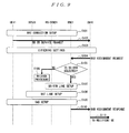
- FIG. 9 a sequence example for setting up a BS-DTM communication line in a Circuit Switching (CS) communication will be described with reference to FIG. 9 .
- the originator UE 41 transmits a communication start request
- a radio connection setup (RRC Connection Setup) is conducted between the UE and the RNC (S101).
- a service request signal (MM CM Service Request) is transmitted to an upper node from the originator UE 41 (S102), and then the setup (including ciphering settings or the like) is started between the ORIGINATOR UE 41 and the upper node (S103).
- a Radio Access Bearer Assignment Request (RAB Assignment Request) is transmitted from the upper node in the CN 10 to the RNC 1, so the BS-DTM for the originator is selected at the RNC (S105). If there are multiple BS-DTMs, the correspondence of the BTS and the BS-DTM is performed when a call is originated. In this situation, as logic of selecting a BS-DTM, examples are a method of assigning resources (in this case, BS-DTM) sequentially and a method of assigning resources randomly. If a BS-DTM cannot be selected, the processing goes onto a release procedure (S105 ⁇ S106).
- the BS-DTM line setup between the BS-DTM and the RNC is performed (S105 ⁇ S107).
- the BTS line setup between the BTS and the RNC is performed (S108).
- radio access setup is performed (S109), and an RAB Assignment Response is transmitted from the RNC 1 to the upper node in the CN 10 (S110).
- the processing is shifted to the settings for the recipient (S111).
- the BS-DTM line setup sequence for the recipient includes a sequence of Paging in the beginning. However, the subsequent sequence is identical to that of the BS-DTM line setup sequence for the originator.
- JP 2006-108891 A (hereinafter, referred to as Document 2).
- JP H08-294168 A (hereinafter, referred to as Document 3) describes that the communication is shifted to a state without the intervention of a base transceiver station, when an identical base transceiver station is used for establishing the communication, and also describes determining of whether or not the positional relationship between terminals are close to each other at the time of shifting.
- a BS-DTM close to the BTS is not always selected.
- far or close in this case denotes not only a physical distance but also a distance including the consideration of a network topology. That is to say, in a case where there are BS-DTMs, one of which is close to and another of which is far from the BTS when the consideration of the network topology is also included, the BS-DTM closest to the BTS is not always selected when a call is originated.
- Document 3 describes the determination of a positional relationship of mobile terminals in a service area of a base transceiver station, and does not address the above drawbacks generated at the time of BS-DTM selection.
- the present invention has been made to address the above drawbacks described in Background Art, and it is an object of the present invention to provide a radio network controller, a radio communication system, and a communication path setting method, whereby loss in a transmission cost, transmission delay of user data, and load on the transmission path between a BTS and a BS-DTM are suppressed.
- a radio network controller that sets up a communication path by use of a transmission device and a base transceiver station to be selected for every call, when communication is originated, the radio network controller comprising select means for selecting the transmission device and the base transceiver station that are close to each other in distance including a consideration of a network topology, wherein the communication path is set up by use of the transmission device and the base transceiver station selected by the select means.
- the radio network controller may further comprise a table in which an identical identifier is applied to the transmission device and the base transceiver station that are close to each other in distance including the consideration of the network topology, wherein the select means selects the transmission device and the base transceiver station to be used for setting up the communication path, on the basis of the identifier. This allows the transmission device and the base transceiver station to be selected in an appropriate manner by referring to the identifier in the table.
- the table may include: a first table indicative of a correspondence relationship between the identifier and the base transceiver station, the identifier being applied in accordance with a distance from a given device in consideration of the network topology; and a second table indicative of a correspondence relationship between the identifier and the transmission device, and the select means refers to the first table and the second table and selects the transmission device.
- the provision of the first table and the second table allows the transmission device and the base transceiver station to be selected in an appropriate manner by referring to the identifier in the table, even if the correspondence relationship among the transmission device, the base transceiver station, and the identifier is complicated.
- a plurality of the identifiers may be applied to a single transmission device in the table, and the select means may select the transmission device on the basis of the number of the identifiers corresponding thereto. This allows the selection of the transmission device with the smallest number of the identifiers to corresponding thereto, thereby setting up a communication path by use of an appropriate transmission device and an appropriate base transceiver station.
- the second table may include a correspondence relationship between a special identifier that is not included in the first table and the transmission device corresponding to the special identifier, and the select means may select the transmission device corresponding to the special identifier, if the identifier extracted by referring to the first table is not included in the second table.
- This allows the transmission device to be commonly used nationwide, if the special identifier is corresponding to the newly provided transmission device. This also allows the transmission device to be selected, even if the information on the correspondence between the identifier and the transmission device is not updated at the time when the facilities are increased or reduced, thereby curtailing the maintenance operations.
- a radio communication system that sets up a communication path by use of a transmission device and a base transceiver station, the system comprising select means for selecting the transmission device and the base transceiver station that are close to each other in distance including a consideration of a network topology, wherein the communication path is set up by use of the transmission device and the base transceiver station selected by the select means.
- a communication path setting method for setting up a communication path by use of a transmission device and a base transceiver station to be selected for every call, when communication is originated, the method comprising: referring to a first table indicative of a correspondence relationship between an identifier and the base transceiver station, the identifier being applied in accordance with a distance from a given device in consideration of a network topology; referring to a second table indicative of a correspondence relationship between the identifier and the transmission device; and setting up the communication path by use of the transmission device that has been selected on the basis of a result of referring to the first table and the second table.
- the provision of the first table and the second table allows the communication path to be set up in an appropriate manner, even if the correspondence relationship among the transmission device, the base transceiver station, and the identifier is complicated.
- the present invention it is made possible to suppress the loss in a transmission path cost, the transmission delay of user data, and the load on a transmission path, to be addressed, between a transmission device and a base transceiver station, in implementing a radio communication system in which use data is turned at a transmission device instead of going through a radio network controller, so as to shorten the communication path of the user data.
- BS-DTM In a case where there are BS-DTMs, one of which is close to and another of which is far from a BTS, it is necessary to provide measures of preferentially selecting a BS-DTM that is closest to the BTS in distance including the consideration of the network topology.
- an identical identifier hereinafter, referred to as Location ID
- a BS-DTM is selected by use of the afore-mentioned Location ID. That is, in the present system, the BS-DTM applied with an identical Location ID is preferentially selected on the basis of the Location ID of the BTS when a call is originated. This is different from the techniques described above in Background Art.
- FIG. 1 is a block diagram illustrative of an example of main configuration of an RNC 1 in a radio communication system according to the present example.
- FIG. 1 illustrates the components relating to a BS-DTM select function.
- a RANAP signal transmitter/receiver 11 a transmitter/receiver for BS-DTM 12, a signal analysis generator 13, and a BS-DTM selector 14 are existing functional components.
- a static memory 17 holds a table (Table) A and a table (Table) B.
- the process flow in the RNC 1 with such a configuration will be described as follows.
- the RANAP signal transmitter/receiver 11 receives a radio access setup request from an upper node, the request is passed onto the signal analysis generator 13 and is then shifted to a BS-DTM select procedure to be described below.
- the signal analysis generator 13 receives a corresponding BTS number, the corresponding BTS number is attached to a BS-DTM select signal, and is passed to the BS-DTM selector 14.
- the Location ID extractor extracting from BTS number 15 extracts the Location ID from the corresponding BTS number.
- the BS-DTM number extractor extracting from Location ID 16 extracts the BS-DTM number from the Location ID.
- Such extracted BS-DTM number is attached to a BS-DTM select signal, and is transmitted back to the signal analysis generator 13.
- the signal analysis generator 13 attaches the extracted BS-DTM number to the BS-DTM line setup signal and is then passed to the transmitter/receiver for BS-DTM 12.
- the transmitter/receiver for BS-DTM 12 transmits a BS-DTM line setup signal to the corresponding BS-DTM.
- the RNC 1 includes a functional part such as a call processor or a device controller.
- a functional part such as a call processor or a device controller.
- the illustration or description of any functional part that is not related to the present embodiment will be omitted herein.
- another configuration can be conceived in such a manner that Table A and Table B are provided in another device, instead of in an RNC. In this case, the RNC will refer to Table A or Table B in another device.
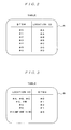
- FIG. 2 illustrates an example of a correspondence table between a BTS number that is an identifier of a BTS and a Location ID thereof.
- a BTS number "#0" has a corresponding Location ID "#A”.
- a BTS number "#1" has a corresponding Location ID “#A”
- a BTS number “#2” has a corresponding Location ID “#B”
- a BTS number “#3” has a corresponding Location ID “#B”
- a BTS number "#4" has a corresponding Location ID “#C”
- a BTS number "#5" has a corresponding Location ID “#C”
- a BTS number "#6” has a corresponding Location ID "#D”.
- FIG. 3 illustrates an example of a correspondence table between a Location ID and a BS-DTM number that is a BS-DTM identifier.
- the BS-DTM number "#2" corresponds to the Location ID "#A”
- the BS-DTM number "#1" corresponds to the Location ID "#C”.
- multiple Location IDs may correspond to a single BS-DTM number. An example thereof is that the Location IDs "#A”, “#B", and "#C" correspond to the BS-DTM number "#0".
- a special identifier that is a Location ID "#*" is provided. If the Location ID extracted from the BTS number is not included in the correspondence table of FIG. 3 , the Location ID is replaced with the afore-mentioned special identifier "#*" so that the BS-DTM can be selected. For instance, if the Location ID is "#D”, the Location ID is replaced with "#*", so the BS-DTM number "#3" is selected.
- FIG. 4 illustrates a flowchart of an example of logic of selecting a BS-DTM when a call is originated in the present example.
- FIG. 4 illustrates the BS-DTM select process (S105), when a call is originated, in the above sequence of FIG. 9 .
- the BTS number used at the start of communication is extracted firstly (step S201).
- the correspondence table A (hereinafter, referred to as Table A) of the BTS number and the Location ID illustrated in FIG. 2 is used to extract the Location ID from the BTS number (step S202).
- step S203 whether or not the Location ID has been extracted from the BTS number is determined (step S203). If the Location ID has not been extracted, the processing goes onto a release procedure (step S203 ⁇ S204).
- step S203 the processing goes to the next procedure (step S203 ⁇ S205).
- Table B the correspondence table B (hereinafter, referred to as Table B) of the Location ID and the BS-DTM number is used to extract the BS-DTM number from the Location ID (step S205).
- step S206 whether or not the BS-DTM number has been extracted from the Location ID is determined. If the BS-DTM number has successfully been extracted, the BS-DTM has been extracted from the BTS number by use of the Location ID, so the processing ends (step S206 ⁇ S207). If the BS-DTM has not been extracted with the use of the Location ID as key information, the processing goes onto a release procedure (step S206 ⁇ S208).
- FIG. 5 is a flowchart illustrative of a process of extracting a BS-DTM from a Location ID, in detail.
- whether or not the Location ID (extracted from Table A with the BTS number used as key information) passed from the former step of S203 is included in Table B is determined firstly (step S301). If the corresponding Location ID is not included in Table B, the corresponding Location ID is replaced with the Location ID "#*" (step S302).
- the Location ID "#*" is a special identifier to be replaced for selecting a BS-DTM, if the Location ID that has been extracted from the BTS number is not included in Table B.
- step S303 whether or not the BS-DTM can be selected with the Location ID "#*" used as key information is determined. If the BS-DTM is successfully selected, the BS-DTM extraction flow by use of the Location ID ends (step S303 ⁇ S304). In other words, the above flow corresponds to a case where the BS-DTM is selected from the BTS #6, and BS-DTM #3 is selected. Conversely, if the BS-DTM cannot be selected, the processing goes onto a release procedure (step S303 ⁇ S305).
- step S301 ⁇ S306 whether or not the BS-DTM corresponding to the Location ID on one-to-one basis can be selected is determined. As a result of the determination, if the BS-DTM corresponding to the Location ID on one-to-one basis can be selected, the BS-DTM extraction flow by use of the Location ID ends (step S301 ⁇ S307).
- the above flow corresponds to a case where the BS-DTM is selected from the BTS "#0", “#1", “#4", and "#5".
- the BS-DTM "#2" is selected in a case where the BTS is "#0" or "#1”
- the BS-DTM "#1" is selected in a case where the BTS is "#4 or "#5".
- step S306 Whether or not there is a BS-DTM corresponding to multiple Location IDs is determined (step S306 ⁇ S308). Then, if there is no BS-DTM corresponding to multiple Location IDs, the processing goes onto a release procedure (step S308 ⁇ S309).
- the BS-DTM corresponding to the smallest number of the Location IDs is selected (step S308 ⁇ S310).
- the BS-DTM extraction flow by use of the Location ID ends (step S310 ⁇ S311).
- the above flow corresponds to a case where the BS-DTM is selected from BTS "#2" or "#3", and the BS-DTM "#1" is selected.
- FIG. 6 is a view illustrative of an image of applying a Location ID.
- an identical Location ID is applied beforehand to a BS-DTM and a BTS that are close to each other in distance including a consideration of a network topology.
- the RNC 1 holds Table A (an example is FIG. 2 ) that is a table in which BTS numbers and Location IDs are corresponding to each other, respectively, and Table B (an example is FIG. 3 ) in which Location IDs and BS-DTM numbers are corresponding to each other, respectively.
- a Location ID "ID1” is applied to the BTS “#0" and the BTS “#1”.
- the Location ID “ID1” identical to those of the BTS “#0” and the BTS “#1” is applied to the BS-DTM "#0", which is close to the BTS "#0" and the BTS “#1".
- a Location ID "ID2” is applied to the BTS “#2” and the BTS “#3”.
- the Location ID “ID2” identical to those of the BTS “#2” and the BTS “#3” is applied to the BS-DTM "#1", which is close to the BTS "#2” and the BTS “#3”.
- the Location IDs "ID1" and “ID2” may be applicable to the BS-DTM "#2" to be a commonly available BS-DTM.
- a new BS-DTM may be provided to be applied with a Location ID "#*" that is a special identifier.
- a Location ID "#*" is a special identifier.
- Such a newly provided BS-DTM will be commonly available nationwide. This allows the selection of the BS-DTM, even if the information of correspondence between the Location ID and the BS-DTM is not updated at the time when facilities are added or reduced. The maintenance operations will be curtailed.
- the special identifier "#*" is not provided, another operation will be needed so that all of the Location IDs nationwide are corresponding to a newly setup BS-DTM. That is, in the present example, the provision of the special identifier "#*" eliminates such an operation.
- FIG. 7 illustrates four BS-DTMs 21 to 24, six BTSs 31 to 36, and eight routers 50 to 57 that are arranged between the BS-DTMs and the BTSs.
- Each of numerals (such as 100m) in FIG. 7 indicates a physical distance between the respective apparatuses.
- a switch that is a mobile switching center
- one of the following examples of criteria (1) to (3) is employed to determine the distance including the consideration of the network topology.
- Example of a criterion is a hop number between routers
- the path with the smallest number of the hops between the routers is assumed to be the shortest distance including the consideration of the network topology between a BTS and a BS-DTM. If this criterion is employed and if a user equipment is included in an area of the BTS 31 or the BTS 32, the BS-DTM 23 is the closest (by way of the router 55 to the router 54). If a user equipment is included in an area of the BTS 33 or the BTS 34, the BS-DTM 22 is the closest (by way of the router 56 to the router 53).
- the BS-DTM 22 is the closest (by way of the router 57 to the router 53) or the BS-DTM 24 is the closest (by way of the router 57 to the router 52).
- Example of a criterion is an overall distance of a transmission path
- the distance of a transmission path between a BTS and a BS-DTM is assumed to be the shortest distance. If this criterion is employed and if a user equipment is included in an area of the BTS 33 or the BTS 34, the BS-DTM 21 is the closest (by way of the router 56, through the router 53, to the router 51).
- Example of a criterion is a distance of the closest transmission path
- the shortest transmission path to the next router is assumed to be the shortest distance. If this criterion is employed and if a user equipment is included in an area of the BTS 33 or the BTS 34, the BS-DTM 24 is the closest (by way of the router 56, through the router 53, to the router 52). Additionally, the information on the paths may be registered beforehand in a fixed manner on the basis of the above criteria (such as the number of the hops, distance, or the like), so as to enable routing in accordance with the registered path information. Further, FIG. 7 illustrates two BTSs included in an area of each router. However, one BTS may be provided, and there are no limitations on the number of the BTSs.
- a communication path setting method for setting up a communication path by use of a transmission device and a base transceiver station to be selected for every call at the time of originating communication.
- the method includes: a step of referring to a first table indicative of a correspondence relationship between an identifier that is applied in accordance with a distance, from a given device, including a consideration of a network topology; a step of referring to a second table indicative of a correspondence relationship between the identifier and the transmission device; and the base transceiver station (this step corresponds to step S202 of FIG.
- this step corresponds to steps S107 and S108 of FIG. 9 , for example).
- a communication path setting method since the first and second tables are used, a communication path is set up in an appropriate manner by referring to the identifier in the tables, even if the correspondence relationship among the transmission device, the base transceiver station, and the identifier is complicated.
- a transmission device is selected on the basis of information on correspondence between a base transceiver station and an identifier, and that between the identifier and a transmission device.
- Such a selection suppresses loss in a transmission path cost, transmission delay of user data, and load applied on a transmission path, to be addressed, between the transmission device and the base transceiver station, in implementing a mobile communication network in which the communication path for user data is shortened by utilizing the user data functionality of the radio network controller and turning the user data at the data transmission device instead of going through a radio network controller.
- multiple identifiers corresponds to a single transmission device so that the transmission device is selected on the basis of the number of the corresponding identifiers, thereby allowing the transmission device to be commonly used and suppressing the equipment cost of the transmission device.
- a special identifier is provided so that if an identifier extracted from the information on correspondence between the base transceiver station and identifier is not found in the information on correspondence between the identifier and the transmission device, the extracted identifier is replaced with the special identifier.
- This allows the selection of the transmission device corresponding to the special identifier. Accordingly, even if the identifier is changed because of the change in the network configuration and there is no identifier that is extracted from the information on correspondence between the identifier and the transmission device, the transmission device can be selected. Confirmation and update operations for confirming and updating whether or not all identifiers correspond to the transmission devices can be curtailed, and the maintenance operations in the network operation can also be curtailed.
- the present invention is applicable to a case where a communication path is set up by use of a transmission device and a base transceiver station to be selected for every call at the time of originating communication.
Landscapes
- Engineering & Computer Science (AREA)
- Computer Networks & Wireless Communication (AREA)
- Signal Processing (AREA)
- Mobile Radio Communication Systems (AREA)
Abstract
Description
- The present invention relates to radio network controllers, radio communication systems, and communication path setting methods, particularly to a radio network controller whereby a communication path is set up by use of a transmission device and a base transceiver station to be selected for every call when communication is originated, a radio communication system including the radio network controller, and a communication path setting method.
- In recent years, 3GPP (3rd Generation Partnership Projects) have proposed a mobile communication system named as W-CDMA system on the basis of Code Division Multiple Access (CDMA) technology. Such a proposed system is specified in 3GPP technical specification TS 21.101.
A mobile communication network shown inFIG. 8 is composed of: a Radio Network Controller (hereinafter referred to as RNC) 1 connected to a core network (hereinafter referred to as CN) 10; and base transceiver stations (hereinafter referred to as BTS) 31, 32, 33, and 34 connected to theRNC 1 via a network (Network) 20.User Equipments 41 and 42 (hereinafter referred to as UE) are capable of making use of mobile communication services to be provided by the BTSs, when they are located within radio service areas. That is to say, when a call is originated from an originator UE 41, a communication path is established with a recipient UE 42 to enable a telephone call and communication. - The above configuration is a mobile radio communication system that complies with 3GPP. In addition to the above configuration, the network of
FIG. 8 also includes Base Station-Data Transfer Modules (hereinafter referred to as BS-DTM) 21 and 22, to be selected by theRNC 1. The BS-DTMs 21 and 22 is equipped with a user data termination/forwarding function, whereby every call is connected by an RNC at the start of communication to establish a communication path with a BTS. - In the network with such a configuration, the provision of the BS-DTMs 21 and 22 enables a telephone call and communication by transmitting the user data back, without passing the user data to the
RNC 1. Accordingly, the communication path of the user data (U-Plane) is shortened as indicated by a thick line in the drawing. Such a technique is described inJP 2004-364054 - Now, a sequence example for setting up a BS-DTM communication line in a Circuit Switching (CS) communication will be described with reference to
FIG. 9 .
InFIG. 9 , the originator UE 41 transmits a communication start request, a radio connection setup (RRC Connection Setup) is conducted between the UE and the RNC (S101). Next, a service request signal (MM CM Service Request) is transmitted to an upper node from the originator UE 41 (S102), and then the setup (including ciphering settings or the like) is started between the ORIGINATOR UE 41 and the upper node (S103). - Subsequently, a Radio Access Bearer Assignment Request (RAB Assignment Request) is transmitted from the upper node in the
CN 10 to theRNC 1, so the BS-DTM for the originator is selected at the RNC (S105). If there are multiple BS-DTMs, the correspondence of the BTS and the BS-DTM is performed when a call is originated.
In this situation, as logic of selecting a BS-DTM, examples are a method of assigning resources (in this case, BS-DTM) sequentially and a method of assigning resources randomly. If a BS-DTM cannot be selected, the processing goes onto a release procedure (S105 → S106). - If a BS-DTM is selected, the BS-DTM line setup between the BS-DTM and the RNC is performed (S105 → S107). Next, the BTS line setup between the BTS and the RNC is performed (S108). Then, radio access setup is performed (S109), and an RAB Assignment Response is transmitted from the
RNC 1 to the upper node in the CN 10 (S110). Subsequently, the processing is shifted to the settings for the recipient (S111). The BS-DTM line setup sequence for the recipient includes a sequence of Paging in the beginning. However, the subsequent sequence is identical to that of the BS-DTM line setup sequence for the originator. - It should be noted that, however, the communication enabled without going through the CN is also described in
JP 2006-108891 A JP H08-294168 A - In the above-described configuration, if there are multiple BS-DTMs, a BS-DTM close to the BTS is not always selected. Herein, "far or close" in this case denotes not only a physical distance but also a distance including the consideration of a network topology. That is to say, in a case where there are BS-DTMs, one of which is close to and another of which is far from the BTS when the consideration of the network topology is also included, the BS-DTM closest to the BTS is not always selected when a call is originated. For this reason, if a BS-DTM far from the BTS is selected, such a selection will cause drawbacks of loss in transmission cost between the selected BS-DTM and the BTS, transmission delay of user data, and load applied on a transmission path. Neither
Document 1 norDocument 2 addresses such drawbacks. -
Document 3 describes the determination of a positional relationship of mobile terminals in a service area of a base transceiver station, and does not address the above drawbacks generated at the time of BS-DTM selection.
The present invention has been made to address the above drawbacks described in Background Art, and it is an object of the present invention to provide a radio network controller, a radio communication system, and a communication path setting method, whereby loss in a transmission cost, transmission delay of user data, and load on the transmission path between a BTS and a BS-DTM are suppressed. - According to an aspect of the present invention, there is provided a radio network controller that sets up a communication path by use of a transmission device and a base transceiver station to be selected for every call, when communication is originated, the radio network controller comprising select means for selecting the transmission device and the base transceiver station that are close to each other in distance including a consideration of a network topology, wherein the communication path is set up by use of the transmission device and the base transceiver station selected by the select means.
This allows an appropriate transmission device to be selected, thereby suppressing the loss in the transmission path cost, transmission delay of user data, and load on the transmission path between a BTS and a BS-DTM are suppressed. - In the above configuration, the radio network controller may further comprise a table in which an identical identifier is applied to the transmission device and the base transceiver station that are close to each other in distance including the consideration of the network topology, wherein the select means selects the transmission device and the base transceiver station to be used for setting up the communication path, on the basis of the identifier.
This allows the transmission device and the base transceiver station to be selected in an appropriate manner by referring to the identifier in the table. - In the above configuration, the table may include: a first table indicative of a correspondence relationship between the identifier and the base transceiver station, the identifier being applied in accordance with a distance from a given device in consideration of the network topology; and a second table indicative of a correspondence relationship between the identifier and the transmission device, and the select means refers to the first table and the second table and selects the transmission device.
The provision of the first table and the second table allows the transmission device and the base transceiver station to be selected in an appropriate manner by referring to the identifier in the table, even if the correspondence relationship among the transmission device, the base transceiver station, and the identifier is complicated. - In the above configuration, a plurality of the identifiers may be applied to a single transmission device in the table, and the select means may select the transmission device on the basis of the number of the identifiers corresponding thereto.
This allows the selection of the transmission device with the smallest number of the identifiers to corresponding thereto, thereby setting up a communication path by use of an appropriate transmission device and an appropriate base transceiver station. - In the above configuration, the second table may include a correspondence relationship between a special identifier that is not included in the first table and the transmission device corresponding to the special identifier, and the select means may select the transmission device corresponding to the special identifier, if the identifier extracted by referring to the first table is not included in the second table.
This allows the transmission device to be commonly used nationwide, if the special identifier is corresponding to the newly provided transmission device. This also allows the transmission device to be selected, even if the information on the correspondence between the identifier and the transmission device is not updated at the time when the facilities are increased or reduced, thereby curtailing the maintenance operations. - According to another aspect of the present invention, there is provided a radio communication system that sets up a communication path by use of a transmission device and a base transceiver station, the system comprising select means for selecting the transmission device and the base transceiver station that are close to each other in distance including a consideration of a network topology, wherein the communication path is set up by use of the transmission device and the base transceiver station selected by the select means.
This allows an appropriate transmission device to be selected, thereby suppressing the loss in the transmission path cost between the base transceiver station and the transmission device, the transmission delay of user data, and the load on the transmission path. - According to further another aspect of the present invention, there is provided a communication path setting method for setting up a communication path by use of a transmission device and a base transceiver station to be selected for every call, when communication is originated, the method comprising: referring to a first table indicative of a correspondence relationship between an identifier and the base transceiver station, the identifier being applied in accordance with a distance from a given device in consideration of a network topology; referring to a second table indicative of a correspondence relationship between the identifier and the transmission device; and setting up the communication path by use of the transmission device that has been selected on the basis of a result of referring to the first table and the second table.
The provision of the first table and the second table allows the communication path to be set up in an appropriate manner, even if the correspondence relationship among the transmission device, the base transceiver station, and the identifier is complicated. - According to an aspect of the present invention, it is made possible to suppress the loss in a transmission path cost, the transmission delay of user data, and the load on a transmission path, to be addressed, between a transmission device and a base transceiver station, in implementing a radio communication system in which use data is turned at a transmission device instead of going through a radio network controller, so as to shorten the communication path of the user data.
-
-
FIG. 1 is a block view illustrative of an example of main components of an RNC in a system according to the present embodiment; -
FIG. 2 is a view illustrative of an example of a correspondence table between a BTS number that is an identifier of a BTS and a Location ID; -
FIG. 3 is a view illustrative of an example of a correspondence table between the Location ID and a BS-DTM number that is an identifier of a BS-DTM; -
FIG. 4 is a flowchart illustrative of an example of logic of selecting the BS-DTM at the time of originating a call according to the present embodiment; -
FIG. 5 is a flowchart illustrative of details of a process of extracting the BS-DTM from the Location ID (step S205); -
FIG. 6 is a view illustrative of an image of applying the Location ID; -
FIG. 7 is a view illustrative of examples of criteria for determining that the distance including the consideration of network topology is close; -
FIG. 8 is a view illustrative of a configuration example of a mobile communication network; and -
FIG. 9 is a view illustrative of a sequence example of setting up a BS-DTM line in circuit switching. -
- 1
- radio network controller
- 10
- core network
- 11
- RANAP signal transmitter/receiver
- 12
- transmitter/receiver for BS-DTM
- 13
- signal analysis generator
- 14
- BS-DTM selector
- 15
- Location ID extractor extracting from BTS number
- 16
- BS-DTM number extractor extracting from Location ID
- 17
- static memory
- 21 - 24
- transmission device
- 31 - 36
- base transceiver station
- 41, 42
- user equipment
- 50 - 57
- router
- A, B
- table
- Embodiments of the present invention will now be described with reference to the drawings. In each of the drawings to be referenced to in the following description, the same components and configurations have the same reference numerals.
The entire configuration of a radio communication system according to the present embodiment is same as that shown inFIG. 8 . In addition, the entire sequence at the time of originating a call according to the present embodiment is same as that shown inFIG. 9 . - In a case where there are BS-DTMs, one of which is close to and another of which is far from a BTS, it is necessary to provide measures of preferentially selecting a BS-DTM that is closest to the BTS in distance including the consideration of the network topology. In the present system, to accomplish the above measure, an identical identifier (hereinafter, referred to as Location ID) is beforehand applied to a BTS and a BS-DTM that are close to each other in distance including the consideration of the network topology.
Additionally, when a call is originated, a BS-DTM is selected by use of the afore-mentioned Location ID. That is, in the present system, the BS-DTM applied with an identical Location ID is preferentially selected on the basis of the Location ID of the BTS when a call is originated. This is different from the techniques described above in Background Art. -
FIG. 1 is a block diagram illustrative of an example of main configuration of anRNC 1 in a radio communication system according to the present example.FIG. 1 illustrates the components relating to a BS-DTM select function.
InFIG. 1 , a RANAP signal transmitter/receiver 11, a transmitter/receiver for BS-DTM 12, asignal analysis generator 13, and a BS-DTM selector 14 are existing functional components. In the present system, there are provided a Location ID extractor extracting fromBTS number 15 and a BS-DTM number extractor extracting fromLocation ID 16. Astatic memory 17 holds a table (Table) A and a table (Table) B. - The process flow in the
RNC 1 with such a configuration will be described as follows. When the RANAP signal transmitter/receiver 11 receives a radio access setup request from an upper node, the request is passed onto thesignal analysis generator 13 and is then shifted to a BS-DTM select procedure to be described below.
In the BS-DTM select procedure, thesignal analysis generator 13 receives a corresponding BTS number, the corresponding BTS number is attached to a BS-DTM select signal, and is passed to the BS-DTM selector 14. Next, the Location ID extractor extracting fromBTS number 15 extracts the Location ID from the corresponding BTS number. - Then, the BS-DTM number extractor extracting from
Location ID 16 extracts the BS-DTM number from the Location ID. Such extracted BS-DTM number is attached to a BS-DTM select signal, and is transmitted back to thesignal analysis generator 13. Thesignal analysis generator 13 attaches the extracted BS-DTM number to the BS-DTM line setup signal and is then passed to the transmitter/receiver for BS-DTM 12. The transmitter/receiver for BS-DTM 12 transmits a BS-DTM line setup signal to the corresponding BS-DTM. - Incidentally, it is common that the
RNC 1 includes a functional part such as a call processor or a device controller. However, the illustration or description of any functional part that is not related to the present embodiment will be omitted herein.
Additionally, another configuration can be conceived in such a manner that Table A and Table B are provided in another device, instead of in an RNC. In this case, the RNC will refer to Table A or Table B in another device. - An example of table configuration of Table A and Table B to be used in the present system will be described with reference to
FIG. 2 and FIG. 3 .
FIG. 2 illustrates an example of a correspondence table between a BTS number that is an identifier of a BTS and a Location ID thereof. InFIG. 2 , a BTS number "#0" has a corresponding Location ID "#A". Likewise, a BTS number "#1" has a corresponding Location ID "#A", a BTS number "#2" has a corresponding Location ID "#B", a BTS number "#3" has a corresponding Location ID "#B", a BTS number "#4" has a corresponding Location ID "#C", a BTS number "#5" has a corresponding Location ID "#C", and a BTS number "#6" has a corresponding Location ID "#D". - Meanwhile,
FIG. 3 illustrates an example of a correspondence table between a Location ID and a BS-DTM number that is a BS-DTM identifier. InFIG. 3 , the BS-DTM number "#2" corresponds to the Location ID "#A", and the BS-DTM number "#1" corresponds to the Location ID "#C".
In addition, as illustrated inFIG. 3 , multiple Location IDs may correspond to a single BS-DTM number. An example thereof is that the Location IDs "#A", "#B", and "#C" correspond to the BS-DTM number "#0". - Furthermore, a special identifier that is a Location ID "#*" is provided. If the Location ID extracted from the BTS number is not included in the correspondence table of
FIG. 3 , the Location ID is replaced with the afore-mentioned special identifier "#*" so that the BS-DTM can be selected.
For instance, if the Location ID is "#D", the Location ID is replaced with "#*", so the BS-DTM number "#3" is selected. -
FIG. 4 illustrates a flowchart of an example of logic of selecting a BS-DTM when a call is originated in the present example.FIG. 4 illustrates the BS-DTM select process (S105), when a call is originated, in the above sequence ofFIG. 9 .
InFIG. 4 , the BTS number used at the start of communication is extracted firstly (step S201). Next, the correspondence table A (hereinafter, referred to as Table A) of the BTS number and the Location ID illustrated inFIG. 2 is used to extract the Location ID from the BTS number (step S202). Then, whether or not the Location ID has been extracted from the BTS number is determined (step S203). If the Location ID has not been extracted, the processing goes onto a release procedure (step S203 → S204). - Meanwhile, if the Location ID has successfully been extracted, the processing goes to the next procedure (step S203 → S205). Next, the correspondence table B (hereinafter, referred to as Table B) of the Location ID and the BS-DTM number is used to extract the BS-DTM number from the Location ID (step S205). Then, whether or not the BS-DTM number has been extracted from the Location ID is determined (step S206). If the BS-DTM number has successfully been extracted, the BS-DTM has been extracted from the BTS number by use of the Location ID, so the processing ends (step S206 → S207). If the BS-DTM has not been extracted with the use of the Location ID as key information, the processing goes onto a release procedure (step S206 → S208).
In a case where the above select logic is employed, regarding the BTS number "#2", for instance, Table A is used at step S202 and the Location ID is "#A". Regarding the Location ID "#A", Table B is used at step S205 and the BS-DTM number is "#1". -
FIG. 5 is a flowchart illustrative of a process of extracting a BS-DTM from a Location ID, in detail. InFIG. 5 , whether or not the Location ID (extracted from Table A with the BTS number used as key information) passed from the former step of S203 is included in Table B is determined firstly (step S301). If the corresponding Location ID is not included in Table B, the corresponding Location ID is replaced with the Location ID "#*" (step S302). The Location ID "#*" is a special identifier to be replaced for selecting a BS-DTM, if the Location ID that has been extracted from the BTS number is not included in Table B. - Next, whether or not the BS-DTM can be selected with the Location ID "#*" used as key information is determined (step S303). If the BS-DTM is successfully selected, the BS-DTM extraction flow by use of the Location ID ends (step S303 → S304). In other words, the above flow corresponds to a case where the BS-DTM is selected from the
BTS # 6, and BS-DTM # 3 is selected. Conversely, if the BS-DTM cannot be selected, the processing goes onto a release procedure (step S303 → S305). - A process of a case where the corresponding Location ID is included in Table B will now be described. The process to be described below is applicable to a case where multiple Location IDs correspond to a single BS-DTM as illustrated in
FIG. 3 . If the corresponding Location ID is included in Table B, whether or not the BS-DTM corresponding to the Location ID on one-to-one basis can be selected is determined (step S301 → S306). As a result of the determination, if the BS-DTM corresponding to the Location ID on one-to-one basis can be selected, the BS-DTM extraction flow by use of the Location ID ends (step S301 → S307). In other words, the above flow corresponds to a case where the BS-DTM is selected from the BTS "#0", "#1", "#4", and "#5". The BS-DTM "#2" is selected in a case where the BTS is "#0" or "#1", whereas the BS-DTM "#1" is selected in a case where the BTS is "#4 or "#5". - If the BS-DTM corresponding to the Location ID on one-to-one basis cannot be selected, the following process will be performed. Whether or not there is a BS-DTM corresponding to multiple Location IDs is determined (step S306 → S308). Then, if there is no BS-DTM corresponding to multiple Location IDs, the processing goes onto a release procedure (step S308 → S309).
- Conversely, if there is a BS-DTM corresponding to multiple Location IDs, the BS-DTM corresponding to the smallest number of the Location IDs is selected (step S308 → S310). The BS-DTM extraction flow by use of the Location ID ends (step S310 → S311). In other words, the above flow corresponds to a case where the BS-DTM is selected from BTS "#2" or "#3", and the BS-DTM "#1" is selected.
-
FIG. 6 is a view illustrative of an image of applying a Location ID. Referring toFIG. 6 , an identical Location ID is applied beforehand to a BS-DTM and a BTS that are close to each other in distance including a consideration of a network topology. Then, theRNC 1 holds Table A (an example isFIG. 2 ) that is a table in which BTS numbers and Location IDs are corresponding to each other, respectively, and Table B (an example isFIG. 3 ) in which Location IDs and BS-DTM numbers are corresponding to each other, respectively. - In the present example, a Location ID "ID1" is applied to the BTS "#0" and the BTS "#1". Next, the Location ID "ID1" identical to those of the BTS "#0" and the BTS "#1" is applied to the BS-DTM "#0", which is close to the BTS "#0" and the BTS "#1".
Also, a Location ID "ID2" is applied to the BTS "#2" and the BTS "#3". Then, the Location ID "ID2" identical to those of the BTS "#2" and the BTS "#3" is applied to the BS-DTM "#1", which is close to the BTS "#2" and the BTS "#3".
Incidentally, as illustrated inFIG. 6 , the Location IDs "ID1" and "ID2" may be applicable to the BS-DTM "#2" to be a commonly available BS-DTM. - Furthermore, a new BS-DTM may be provided to be applied with a Location ID "#*" that is a special identifier. Such a newly provided BS-DTM will be commonly available nationwide. This allows the selection of the BS-DTM, even if the information of correspondence between the Location ID and the BS-DTM is not updated at the time when facilities are added or reduced. The maintenance operations will be curtailed.
Moreover, if the special identifier "#*" is not provided, another operation will be needed so that all of the Location IDs nationwide are corresponding to a newly setup BS-DTM.
That is, in the present example, the provision of the special identifier "#*" eliminates such an operation. - Referring now to
FIG. 7 , examples of criteria for determining that it is close in distance including the consideration of the network topology will be described.FIG. 7 illustrates four BS-DTMs 21 to 24, sixBTSs 31 to 36, and eightrouters 50 to 57 that are arranged between the BS-DTMs and the BTSs. Each of numerals (such as 100m) inFIG. 7 indicates a physical distance between the respective apparatuses. Instead of each router, a switch (that is a mobile switching center) may be provided. In such a network configuration, one of the following examples of criteria (1) to (3) is employed to determine the distance including the consideration of the network topology. - The path with the smallest number of the hops between the routers is assumed to be the shortest distance including the consideration of the network topology between a BTS and a BS-DTM. If this criterion is employed and if a user equipment is included in an area of the
BTS 31 or theBTS 32, the BS-DTM 23 is the closest (by way of therouter 55 to the router 54). If a user equipment is included in an area of theBTS 33 or theBTS 34, the BS-DTM 22 is the closest (by way of therouter 56 to the router 53). If a user equipment is included in an area of theBTS 35 or theBTS 36, the BS-DTM 22 is the closest (by way of therouter 57 to the router 53) or the BS-DTM 24 is the closest (by way of therouter 57 to the router 52). - The distance of a transmission path between a BTS and a BS-DTM is assumed to be the shortest distance. If this criterion is employed and if a user equipment is included in an area of the
BTS 33 or theBTS 34, the BS-DTM 21 is the closest (by way of therouter 56, through therouter 53, to the router 51). - The shortest transmission path to the next router (or switch) is assumed to be the shortest distance. If this criterion is employed and if a user equipment is included in an area of the
BTS 33 or theBTS 34, the BS-DTM 24 is the closest (by way of therouter 56, through therouter 53, to the router 52).
Additionally, the information on the paths may be registered beforehand in a fixed manner on the basis of the above criteria (such as the number of the hops, distance, or the like), so as to enable routing in accordance with the registered path information. Further,FIG. 7 illustrates two BTSs included in an area of each router. However, one BTS may be provided, and there are no limitations on the number of the BTSs. - In the above radio communication system, a communication path setting method, to be described below, is employed. That is a communication path setting method for setting up a communication path by use of a transmission device and a base transceiver station to be selected for every call at the time of originating communication. The method includes: a step of referring to a first table indicative of a correspondence relationship between an identifier that is applied in accordance with a distance, from a given device, including a consideration of a network topology; a step of referring to a second table indicative of a correspondence relationship between the identifier and the transmission device; and the base transceiver station (this step corresponds to step S202 of
FIG. 4 , for example); and a step of setting up a communication path by use of the transmission device that has been selected on the basis of a result of referring to the first and second tables (this step corresponds to steps S107 and S108 ofFIG. 9 , for example).
With such a communication path setting method, since the first and second tables are used, a communication path is set up in an appropriate manner by referring to the identifier in the tables, even if the correspondence relationship among the transmission device, the base transceiver station, and the identifier is complicated. - According to an aspect of the present invention as described heretofore, a transmission device is selected on the basis of information on correspondence between a base transceiver station and an identifier, and that between the identifier and a transmission device. Such a selection suppresses loss in a transmission path cost, transmission delay of user data, and load applied on a transmission path, to be addressed, between the transmission device and the base transceiver station, in implementing a mobile communication network in which the communication path for user data is shortened by utilizing the user data functionality of the radio network controller and turning the user data at the data transmission device instead of going through a radio network controller.
In addition, multiple identifiers corresponds to a single transmission device so that the transmission device is selected on the basis of the number of the corresponding identifiers, thereby allowing the transmission device to be commonly used and suppressing the equipment cost of the transmission device. - Further, a special identifier is provided so that if an identifier extracted from the information on correspondence between the base transceiver station and identifier is not found in the information on correspondence between the identifier and the transmission device, the extracted identifier is replaced with the special identifier. This allows the selection of the transmission device corresponding to the special identifier. Accordingly, even if the identifier is changed because of the change in the network configuration and there is no identifier that is extracted from the information on correspondence between the identifier and the transmission device, the transmission device can be selected. Confirmation and update operations for confirming and updating whether or not all identifiers correspond to the transmission devices can be curtailed, and the maintenance operations in the network operation can also be curtailed.
- The present invention is applicable to a case where a communication path is set up by use of a transmission device and a base transceiver station to be selected for every call at the time of originating communication.
Claims (7)
- A radio network controller that sets up a communication path by use of a transmission device and a base transceiver station to be selected for every call, when communication is originated, the radio network controller comprising select means for selecting the transmission device and the base transceiver station that are close to each other in distance including a consideration of a network topology,
wherein the communication path is set up by use of the transmission device and the base transceiver station selected by the select means. - The radio network controller according to claim 1, further comprising a table in which an identical identifier is applied to the transmission device and the base transceiver station that are close to each other in distance including the consideration of the network topology,
wherein the select means selects the transmission device and the base transceiver station to be used for setting up the communication path, on the basis of the identifier. - The radio network controller according to claim 2, wherein:the table comprises: a first table indicative of a correspondence relationship between the identifier and the base transceiver station, the identifier being applied in accordance with a distance from a given device in consideration of the network topology; and a second table indicative of a correspondence relationship between the identifier and the transmission device, andthe select means refers to the first table and the second table and selects the transmission device.
- The radio network controller according to claim 2 or 3, wherein:a plurality of the identifiers are applied to a single transmission device in the table, andthe select means selects the transmission device on the basis of the number of the identifiers to be corresponding thereto.
- The radio network controller according to claim 3, wherein:the second table includes a correspondence relationship between a special identifier that is not included in the first table and the transmission device corresponding to the special identifier, andthe select means selects the transmission device corresponding to the special identifier, if the identifier extracted by referring to the first table is not included in the second table.
- A radio communication system that sets up a communication path by use of a transmission device and a base transceiver station, the system comprising select means for selecting the transmission device and the base transceiver station that are close to each other in distance including a consideration of a network topology, wherein the communication path is set up by use of the transmission device and the base transceiver station selected by the select means.
- A communication path setting method for setting up a communication path by use of a transmission device and a base transceiver station to be selected for every call, when communication is originated, the method comprising:referring to a first table indicative of a correspondence relationship between an identifier and the base transceiver station, the identifier being applied in accordance with a distance from a given device in consideration of a network topology;referring to a second table indicative of a correspondence relationship between the identifier and the transmission device; andsetting up the communication path by use of the transmission device that has been selected on the basis of a result of referring to the first table and the second table.
Applications Claiming Priority (2)
| Application Number | Priority Date | Filing Date | Title |
|---|---|---|---|
| JP2007160288A JP4787792B2 (en) | 2007-06-18 | 2007-06-18 | Radio control apparatus, radio communication system, and communication path setting method |
| PCT/JP2008/061159 WO2008156120A1 (en) | 2007-06-18 | 2008-06-18 | Radio control device, radio communication system, and communication path setting method |
Publications (2)
| Publication Number | Publication Date |
|---|---|
| EP2169975A1 true EP2169975A1 (en) | 2010-03-31 |
| EP2169975A4 EP2169975A4 (en) | 2013-10-09 |
Family
ID=40156279
Family Applications (1)
| Application Number | Title | Priority Date | Filing Date |
|---|---|---|---|
| EP08765726.8A Withdrawn EP2169975A4 (en) | 2007-06-18 | 2008-06-18 | RADIO CONTROL DEVICE, RADIO COMMUNICATION SYSTEM, AND METHOD OF ESTABLISHING COMMUNICATION PATH |
Country Status (5)
| Country | Link |
|---|---|
| US (1) | US20100278126A1 (en) |
| EP (1) | EP2169975A4 (en) |
| JP (1) | JP4787792B2 (en) |
| CN (1) | CN101675703B (en) |
| WO (1) | WO2008156120A1 (en) |
Cited By (1)
| Publication number | Priority date | Publication date | Assignee | Title |
|---|---|---|---|---|
| CN111194563A (en) * | 2017-10-13 | 2020-05-22 | 瑞典爱立信有限公司 | Method for facilitating selection of network access for a wireless communication device |
Family Cites Families (27)
| Publication number | Priority date | Publication date | Assignee | Title |
|---|---|---|---|---|
| JPH08294168A (en) | 1995-04-21 | 1996-11-05 | Casio Comput Co Ltd | Wireless communication system and wireless communication terminal |
| US7783299B2 (en) * | 1999-01-08 | 2010-08-24 | Trueposition, Inc. | Advanced triggers for location-based service applications in a wireless location system |
| US7072656B2 (en) * | 1999-03-16 | 2006-07-04 | Telefonaktiebolaget Lm Ericsson (Publ) | Handover in a shared radio access network environment using subscriber-dependent neighbor cell lists |
| US6871187B1 (en) * | 2000-06-13 | 2005-03-22 | Dell Products L.P. | Translator for use in an automated order entry system |
| US6804532B1 (en) * | 2000-12-22 | 2004-10-12 | Cisco Technology, Inc. | System and method for re-routing communications based on wireless communication link quality |
| JP3717805B2 (en) * | 2001-06-07 | 2005-11-16 | 三洋電機株式会社 | Mobile communication terminal |
| DE60212404T2 (en) * | 2001-08-21 | 2007-01-04 | Telefonaktiebolaget Lm Ericsson (Publ) | MULTIPLE SHIPMENT IN PACKET-MEDIATED POINT-TO-POINT NETWORKS |
| JP4318884B2 (en) * | 2002-03-06 | 2009-08-26 | ソフトバンクテレコム株式会社 | Neighboring router recognition method in packet communication network |
| JP3924502B2 (en) * | 2002-07-04 | 2007-06-06 | 富士通株式会社 | Mobile communication method and mobile communication system |
| JP4217544B2 (en) * | 2003-06-05 | 2009-02-04 | 株式会社エヌ・ティ・ティ・ドコモ | Mobile communication system, control apparatus, and communication method |
| WO2004114695A1 (en) * | 2003-06-19 | 2004-12-29 | Mitsubishi Denki Kabushiki Kaisha | Radio base station device and mobile communication system |
| JP3798769B2 (en) * | 2003-07-25 | 2006-07-19 | 日本テレコム株式会社 | Data communication apparatus and data communication system |
| JP4071700B2 (en) * | 2003-11-07 | 2008-04-02 | 株式会社エヌ・ティ・ティ・ドコモ | Mobile communication system, extension transmission / reception device, radio base station device, radio control device, and mobile switching center |
| JP4312655B2 (en) * | 2004-05-11 | 2009-08-12 | 株式会社神戸製鋼所 | WIRELESS NETWORK COMMUNICATION SYSTEM, SOURCE WIRELESS TERMINAL USED IN THE SYSTEM, AND WIRELESS COMMUNICATION ROUTE ROUTING METHOD |
| JP4776202B2 (en) * | 2004-10-01 | 2011-09-21 | 株式会社エヌ・ティ・ティ・ドコモ | Communication path switching system and method |
| US7542761B2 (en) * | 2004-10-06 | 2009-06-02 | At&T Mobility Ii Llc | Voice quality on a communication link based on customer feedback |
| ES2529680T3 (en) * | 2004-12-03 | 2015-02-24 | Telecom Italia S.P.A. | Activation of combinational services in a communications network |
| CN101185357B (en) * | 2005-03-29 | 2011-06-01 | 富士通株式会社 | switch system |
| EP1884090B1 (en) * | 2005-05-27 | 2014-08-13 | Telefonaktiebolaget L M Ericsson (publ) | Local switching in radio access networks |
| DE502005002726D1 (en) * | 2005-05-27 | 2008-03-20 | Tektronix Int Sales Gmbh | Method and apparatus for providing ATM cells ordered by ATM channels at an interface located between a first and a second node of a transmission system |
| WO2007095473A1 (en) * | 2006-02-10 | 2007-08-23 | Qualcomm Incorporated | Signaling with opaque ue identities |
| JP4897038B2 (en) * | 2006-03-20 | 2012-03-14 | ケイティーフリーテル カンパニー リミテッド | Traffic information measuring method and system using CDMA network |
| US8081923B1 (en) * | 2007-02-13 | 2011-12-20 | Extenet Systems Inc. | Method and apparatus for providing location services for a distributed network |
| US20080194226A1 (en) * | 2007-02-13 | 2008-08-14 | Antonio Rivas | Method and Apparatus for Providing Location Services for a Distributed Network |
| US20080222701A1 (en) * | 2007-03-05 | 2008-09-11 | Nokia Corporation | Using secondary bearer to detect proximity of a device |
| US7830817B1 (en) * | 2007-12-05 | 2010-11-09 | Sprint Spectrum L.P. | Vocoder selection based on location of client device |
| EP2250832B1 (en) * | 2007-12-31 | 2015-07-01 | Telecom Italia S.p.A. | Method and system for optimizing the configuration of a wireless mobile communications network |
-
2007
- 2007-06-18 JP JP2007160288A patent/JP4787792B2/en not_active Expired - Fee Related
-
2008
- 2008-06-18 EP EP08765726.8A patent/EP2169975A4/en not_active Withdrawn
- 2008-06-18 US US12/665,546 patent/US20100278126A1/en not_active Abandoned
- 2008-06-18 CN CN2008800146152A patent/CN101675703B/en not_active Expired - Fee Related
- 2008-06-18 WO PCT/JP2008/061159 patent/WO2008156120A1/en not_active Ceased
Cited By (2)
| Publication number | Priority date | Publication date | Assignee | Title |
|---|---|---|---|---|
| CN111194563A (en) * | 2017-10-13 | 2020-05-22 | 瑞典爱立信有限公司 | Method for facilitating selection of network access for a wireless communication device |
| US11627520B2 (en) | 2017-10-13 | 2023-04-11 | Telefonaktiebolaget Lm Ericsson (Publ) | Method of facilitating selection of network access for wireless communication devices |
Also Published As
| Publication number | Publication date |
|---|---|
| US20100278126A1 (en) | 2010-11-04 |
| WO2008156120A1 (en) | 2008-12-24 |
| EP2169975A4 (en) | 2013-10-09 |
| CN101675703B (en) | 2013-07-03 |
| JP4787792B2 (en) | 2011-10-05 |
| CN101675703A (en) | 2010-03-17 |
| JP2008312137A (en) | 2008-12-25 |
Similar Documents
| Publication | Publication Date | Title |
|---|---|---|
| JP4554868B2 (en) | Reassignment method for in-zone wireless network controller using signaling for linking transport channels | |
| US7164917B2 (en) | Radio access network apparatus and mobile communication system using the same | |
| KR100801132B1 (en) | Method and system for unifying resource allocation between time division duplex and frequency division duplex in wireless communication system | |
| EP1797737B1 (en) | Transfer of a user equipment in a communication system | |
| JP5383025B2 (en) | Flexible network architecture with user group support | |
| EP2514240A1 (en) | Resource sharing in communications systems | |
| EP3741144A1 (en) | Interconnections between the core networks | |
| JP2005295189A (en) | Mobile communication system and its handover control method | |
| JP5082657B2 (en) | Mobile communication system and mobile terminal device | |
| US7616958B2 (en) | Method for setting cell information in radio access network | |
| CN101031146B (en) | Implementation method, device and system of network switching | |
| JP5645035B2 (en) | Communications system | |
| JP4760531B2 (en) | Mobile communication system, radio base station control device, and operation control method | |
| EP2169975A1 (en) | Radio control device, radio communication system, and communication path setting method | |
| KR20190035397A (en) | Method, mobility management entity and path manager apparatus for selecting core network | |
| JP2010141602A (en) | Core network device, radio network control apparatus, position registration method, and radio network system | |
| JP2009225394A (en) | Mobile communication system | |
| US7391752B1 (en) | Method for generation of unique mobile station IDs in a 1×EVDO network | |
| JP4389632B2 (en) | Heterogeneous wireless service distribution system based on 3G technology | |
| CN111698793B (en) | Communication method and device | |
| CN109219077B (en) | Resource selection method and device | |
| JP5643365B2 (en) | Wireless communication system, user plane control apparatus and communication method therefor | |
| WO2010075896A1 (en) | Base station apparatus and method for routing a connection to an interface of the base station apparatus |
Legal Events
| Date | Code | Title | Description |
|---|---|---|---|
| PUAI | Public reference made under article 153(3) epc to a published international application that has entered the european phase |
Free format text: ORIGINAL CODE: 0009012 |
|
| 17P | Request for examination filed |
Effective date: 20091124 |
|
| AK | Designated contracting states |
Kind code of ref document: A1 Designated state(s): AT BE BG CH CY CZ DE DK EE ES FI FR GB GR HR HU IE IS IT LI LT LU LV MC MT NL NO PL PT RO SE SI SK TR |
|
| AX | Request for extension of the european patent |
Extension state: AL BA MK RS |
|
| DAX | Request for extension of the european patent (deleted) | ||
| A4 | Supplementary search report drawn up and despatched |
Effective date: 20130909 |
|
| RIC1 | Information provided on ipc code assigned before grant |
Ipc: H04W 76/02 20090101AFI20130903BHEP |
|
| STAA | Information on the status of an ep patent application or granted ep patent |
Free format text: STATUS: THE APPLICATION HAS BEEN WITHDRAWN |
|
| 18W | Application withdrawn |
Effective date: 20131107 |