EP2169862A1 - Radio communication control method, base station device, and user device - Google Patents
Radio communication control method, base station device, and user device Download PDFInfo
- Publication number
- EP2169862A1 EP2169862A1 EP08765681A EP08765681A EP2169862A1 EP 2169862 A1 EP2169862 A1 EP 2169862A1 EP 08765681 A EP08765681 A EP 08765681A EP 08765681 A EP08765681 A EP 08765681A EP 2169862 A1 EP2169862 A1 EP 2169862A1
- Authority
- EP
- European Patent Office
- Prior art keywords
- division number
- control information
- distributed
- transmission
- data
- Prior art date
- Legal status (The legal status is an assumption and is not a legal conclusion. Google has not performed a legal analysis and makes no representation as to the accuracy of the status listed.)
- Withdrawn
Links
Images






Classifications
-
- H—ELECTRICITY
- H04—ELECTRIC COMMUNICATION TECHNIQUE
- H04L—TRANSMISSION OF DIGITAL INFORMATION, e.g. TELEGRAPHIC COMMUNICATION
- H04L5/00—Arrangements affording multiple use of the transmission path
- H04L5/0001—Arrangements for dividing the transmission path
- H04L5/0003—Two-dimensional division
- H04L5/0005—Time-frequency
- H04L5/0007—Time-frequency the frequencies being orthogonal, e.g. OFDM(A) or DMT
-
- H—ELECTRICITY
- H04—ELECTRIC COMMUNICATION TECHNIQUE
- H04L—TRANSMISSION OF DIGITAL INFORMATION, e.g. TELEGRAPHIC COMMUNICATION
- H04L1/00—Arrangements for detecting or preventing errors in the information received
- H04L1/0001—Systems modifying transmission characteristics according to link quality, e.g. power backoff
- H04L1/0036—Systems modifying transmission characteristics according to link quality, e.g. power backoff arrangements specific to the receiver
- H04L1/0038—Blind format detection
-
- H—ELECTRICITY
- H04—ELECTRIC COMMUNICATION TECHNIQUE
- H04L—TRANSMISSION OF DIGITAL INFORMATION, e.g. TELEGRAPHIC COMMUNICATION
- H04L5/00—Arrangements affording multiple use of the transmission path
- H04L5/0091—Signalling for the administration of the divided path, e.g. signalling of configuration information
-
- H—ELECTRICITY
- H04—ELECTRIC COMMUNICATION TECHNIQUE
- H04L—TRANSMISSION OF DIGITAL INFORMATION, e.g. TELEGRAPHIC COMMUNICATION
- H04L5/00—Arrangements affording multiple use of the transmission path
- H04L5/0091—Signalling for the administration of the divided path, e.g. signalling of configuration information
- H04L5/0092—Indication of how the channel is divided
-
- H—ELECTRICITY
- H04—ELECTRIC COMMUNICATION TECHNIQUE
- H04W—WIRELESS COMMUNICATION NETWORKS
- H04W72/00—Local resource management
- H04W72/04—Wireless resource allocation
- H04W72/044—Wireless resource allocation based on the type of the allocated resource
- H04W72/0453—Resources in frequency domain, e.g. a carrier in FDMA
-
- H—ELECTRICITY
- H04—ELECTRIC COMMUNICATION TECHNIQUE
- H04W—WIRELESS COMMUNICATION NETWORKS
- H04W72/00—Local resource management
- H04W72/20—Control channels or signalling for resource management
- H04W72/23—Control channels or signalling for resource management in the downlink direction of a wireless link, i.e. towards a terminal
-
- H—ELECTRICITY
- H04—ELECTRIC COMMUNICATION TECHNIQUE
- H04L—TRANSMISSION OF DIGITAL INFORMATION, e.g. TELEGRAPHIC COMMUNICATION
- H04L5/00—Arrangements affording multiple use of the transmission path
- H04L5/003—Arrangements for allocating sub-channels of the transmission path
- H04L5/0032—Distributed allocation, i.e. involving a plurality of allocating devices, each making partial allocation
-
- H—ELECTRICITY
- H04—ELECTRIC COMMUNICATION TECHNIQUE
- H04L—TRANSMISSION OF DIGITAL INFORMATION, e.g. TELEGRAPHIC COMMUNICATION
- H04L5/00—Arrangements affording multiple use of the transmission path
- H04L5/003—Arrangements for allocating sub-channels of the transmission path
- H04L5/0037—Inter-user or inter-terminal allocation
Definitions
- the present invention generally relates to a mobile communication technique. More particularly, the present invention relates to a radio communication control method including efficient transmission control of radio resources when performing distributed transmission in which data is transmitted while distributing the data by using divided resource blocks, and relates to configurations of a base station apparatus and a user apparatus.
- OFDM orthogonal frequency division multiplexing
- resource blocks In the OFDMA, band is divided into chunks called resource blocks (RB) so as to frequency-multiplex a plurality of users.
- RB resource blocks
- assignment/transmission schemes for resource blocks two schemes which are a localized RB scheme and a distributed RB scheme are defined (refer to non-patent document 1, for example).
- a downlink signal is generated and transmitted by distributing subdivided frequency components over a wideband.
- frequency diversity can be expected, so that this scheme is advantageous for data transmission by a user of large mobility, and for periodical transmission of small-sized data like voice packets (VoIP).
- VoIP voice packets
- each resource block assigned by the base station is specified by a resource block number (RB index).
- RB index resource block number
- the base station specifies that a RB number 2 is assigned in the distributed RB scheme, it is uniquely specified that the left half of the physical resource block number 2 and the left half of the physical resource block number 8 are used.
- a relative resource block number assigned by the base station may be called "virtual resource block number" in a sense of distinguishing from the actual physical resource block number.
- Fig. 2 it is proposed to allow coexistence of both of the localized RB scheme and the distributed RB scheme according to situations of users (refer to non-patent document 2, for example).
- a part of localized RBs assigned by the base station is replaced with distributed RBs.
- positions used for distributed transmission are determined by a division number irrespective of N DRB . More particularly, a k-th block and a (k+6)-th block form a pair, and the pair is not changed irrespective of N DRS .
- the number (division number) of blocks into which one physical resource block is divided is determined in a fixed manner for each cell.
- the user apparatus recognizes mapping relationship between resource block numbers assigned by the base station in the distributed transmission and actual physical resource block positions, by using a broadcast channel and the like.
- the user apparatus after receiving, from the base station, a notification that the user apparatus is a target of distributed transmission in the current TTI, the user apparatus can receive, demodulate and decode a data channel at corresponding physical resource block positions based on the assigned virtual resource block numbers and the division number which is determined in a fixed manner.
- waste occurs if the number of total resource blocks assigned to a user in the distributed scheme is not an integral multiple of the division number of the resource block (in the above-mentioned example, since the resource block is divided into 2, the division number is 2).
- the resource block number N DRB for distributed transmission for example, resource assignment to a user moving at high speed
- the fixed division number is 2
- the resource block cannot be divided into 2 for distribution unless 6 resource blocks are reserved by incrementing N DRB to 6.
- An object of the present invention is to provide a resource assignment control method which can eliminate resource waste and can maintain frequency diversity effect.
- the division number of one resource block is not fixed when performing distributed transmission, and the division number is adaptively (dynamically) changed according to the number N DRB of resource blocks of the distributed scheme or according to using bandwidth.
- the user apparatus needs to know the current division number in order to receive and decode a distributed-transmitted data channel addressed to the user apparatus at proper physical resource blocks.
- methods for detecting the division number by the user apparatus there are:
- the method (1) for reporting division number there are (1a) a method for reporting the division number as common control information by preparing a control channel field common to a plurality of users, and (1b) a method for preparing a field for reporting the division number in dedicated control information for each user.
- (1a) a method for reporting the division number as common control information by preparing a control channel field common to a plurality of users and (1b) a method for preparing a field for reporting the division number in dedicated control information for each user.
- every user apparatus to which distributed transmission is assigned decodes the field of the common control information necessarily.
- the division number is associated with each using bandwidth beforehand, so that both of the base station and the user apparatus recognizes the correspondence relationship, and the user apparatus determines the division number based on bandwidth information broadcasted from the base station.
- the base station apparatus includes:
- the base station apparatus includes:
- Each of base station apparatuses of the above-mentioned embodiments may be configured to further include a control information generation unit configured to generate control information for reporting the determined division number to one or more user apparatuses.
- control information generation unit includes the division number into the control information as common control information common to the one or more user apparatuses.
- the control information generation unit may be configured to include the division number into the control information as dedicated control information which is to be reported individually to each of the one or more user apparatuses.
- a configuration of a user apparatus is provided in the case when the division number is not reported.
- the user apparatus includes:
- a configuration of a user apparatus in the case when the division number is changed according to the using bandwidth.
- the user apparatus includes:
- a radio communication control method for performing distributed transmission using a division number according to the number of resource blocks used for the distributed transmission. This method includes the steps of:
- a radio communication control method for performing distributed transmission using a division number according to the using bandwidth. This method includes the steps of:
- a step of generating control information for reporting the determined division number to the one or more user apparatuses may be included.
- the division number may be included into the control information as common control information common to the one or more user apparatuses, and the division number may be included into the control information as dedicated control information which is to be reported individually to each of the one or more user apparatuses.
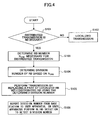
- Fig. 4 is a flowchart of the distribute transmission method according to the first embodiment of the present invention.
- the division number of the resource block is adaptively determined according to the number N DRB of resource blocks to be used for distributed transmission.
- step S101 necessity of distributed transmission is determined at a TTI of transmission timing.
- the determination is performed in the base station for each user apparatus in a cell based on the communication quality (SINR etc.), moving speed, QoS and the like. For example, when the moving speed of the user apparatus exceeds a predetermined speed, or when voice communication is performed, distributed transmission is determined to be necessary. When mobility is small, or when there are only users who transmit large capacity data with high quality, distributed transmission is determined to be unnecessary.
- N DRB is a sum total of resource block sizes (numbers) necessary for data transmission of target users of the distributed transmission.
- the division number of the resource block is determined according to the value (S104).
- the division number can be obtained by storing necessary correspondence relationship between the distributed RB number N DRB and the division number in the base station beforehand.
- N DRB is associated with the division number such that the division number is 2 when N DRB is 2, the division number is 3 when N DRB is 3, and the division number is 2 when N DRB is 4, and the like.
- the number N DRB of localized RBs are replaced with distributed RBs based on a pattern according to the obtained division number, so that the distributed RBs are transmitted (S105).
- the base station reports the division number to the user apparatus using a control channel, or instead of reporting the division number, the division number is detected by the user apparatus by performing blind detection (S106).
- the method for reporting the division number is described later.
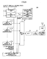
- Fig. 5 is a schematic block diagram of the base station apparatus 10A used in the first embodiment.
- the base station apparatus 10A includes a scheduler 11, a division number determination unit 13A, data generation processing units 17-1 - 17-n for each user, a control information generation processing unit 19, and a multiplexing unit 20.
- the scheduler 11 receives transmission data addressed to each user apparatus from a buffer which is not shown in the figure, and the scheduler 11 receives user apparatus information such as user quality (SINR etc.), requested service quality QoS, moving speed f D and the like which have been received in the uplink and demodulated.
- SINR user quality
- QoS moving speed f D and the like
- the division number determination unit 13A determines the division number according to N DRB based on a N DRB -division number correspondence table 15, and outputs the determined division number to the control information generation unit 19 and the multiplexing unit 20.
- Fig. 6 shows an example of the N DRB -division number correspondence table 15. In this example, the resource block is divided into 2 when N DRB is 2 and 4, and the resource block is divided into 3 when N DRB is 3, 5 and 6.
- the scheduler 11 determines which resource block and what kind of transmission scheme are used for transmitting a data channel for each of user apparatuses (which include a user apparatus of a target of distributed transmission and a user apparatus of a target of localized transmission), and the scheduler 11 provides the determined information to the control information generation processing unit 19.
- the input information to the control information generation unit 19 includes information (L/D information) indicating whether a user is a target of distributed transmission or a target of localized transmission, assigned resource block numbers, transmission format, and the like.
- Each data generation processing unit 17 generates a data signal with a resource block size (number) determined by the scheduler 11, and performs channel coding and data modulation using a predetermined coding rate and modulation scheme, for each corresponding user apparatus.
- the control information generation processing unit 19 generates a control channel based on the L/D information of each user, assigned RB number and transmission format information received from the scheduler 11 and based on the division number information received from the division number determination unit 13A. Then, the control information generation processing unit 19 performs channel coding and modulation for the control channel.
- the multiplexing unit 20 maps (multiplexes), onto a frequency axis, a control channel, data channels for a plurality of users, and other physical channels (not shown in the figure) as necessary.
- the multiplexing unit 20 includes a pattern for mapping into physical resource blocks, so that the multiplexing unit 20 performs user multiplexing based on the division number supplied from the division number determination unit 13A.
- the multiplexed signal is modulated by inverse Fourier transform in the inverse fast Fourier transform unit 21.
- a guard interval is added using a cyclic prefix scheme in the CP adding unit 22, and, D/A conversion, RF conversion and band limitation and the like are performed by the RF transmission circuit 23.
- transmission power is adjusted by the power amplifier 24, so that the signal is transmitted from the antenna.
- the division number determination unit 13A may be embedded into the scheduler 11 as a unit.
- Fig. 7 is a diagram showing an example of distributed transmission based on variable division number according to the value of N DRB .
- N DRB 5
- data is not transmitted in the shaded area (assigned resource block number 10) so that waste of one physical resource block occurs.
- Fig. 8A shows a first reporting method (1a) for reporting the division number to the user apparatus from the base station apparatus 10A in each TTI.
- a field 51 which is common to user apparatuses which are targets of the distributed transmission is prepared in a control channel. Every use apparatus which is the target of the distributed transmission demodulates the field 51 for this common control information.
- Information indicating whether a user apparatus is a target of the distributed transmission is inserted into dedicated control information fields 52-1, 52-2 and 52-3 for UE1, UE2 and UE3 respectively. For example, by providing one bit area in the field 52 for each user apparatus, information (L/D) indicating whether to apply distributed transmission or localized transmission is embedded into the one bit area.
- Such control channel is generated by the control information generation processing unit 19.
- Fig. 8A distributed transmission is performed for the user apparatuses UE1 and UE2, and localized transmission is performed for UE3.
- the user apparatus UE1 recognizes that assignment has been performed for UE1 since the control channel includes the field UE1 (52-1) corresponding to the ID number of UE1. Then, the user apparatus UE1 extracts L/D information and assigned resource block number form the dedicated control information field 52-1.
- the dedicated control information field 52-1 includes control information such as modulation method and channel coding rate and the like.
- the user apparatus UE1 After the user apparatus UE1 detects that the user apparatus UE1 is a target of the distributed transmission by the L/D information, the user apparatus UE1 demodulates the common control information field 51 so as to recognize the division number in the current TTI. Similarly, the user apparatus UE2 recognizes that the user apparatus UE2 is a target of the distributed transmission based on the control information field 52-2, and demodulates the common control information field 51. On the other hand, the user apparatus UE3 detects that it is a target of the localized transmission, and the user apparatus UE3 does not demodulate the common control information field 51.
- Fig. 9A shows a second reporting method (1a) for reporting the division number in each TTI from the base station apparatus 10A to the user apparatus.
- a dedicated field 53 indicating the division number is provided for each user apparatus which is the target of the distributed transmission.
- the use apparatuses UE1 and UE2 are provided with dedicated division number fields 53-1 and 53-2 addressed to the respective apparatuses.
- each of the user apparatuses recognizes that it is a target of the distributed transmission, so that the user apparatuses can receive and demodulate data at distributed proper positions in actual physical resource blocks by using the resource block numbers included in the dedicated control information fields 52-1 and 52-2, and the division number in the current TTI included in the division number fields 53-1 and 53-2. Since there is no dedicated division number field for the user apparatus UE3, the user apparatus UE3 recognizes that localized transmission is performed, and receives and demodulates user data at actual positions of the physical resource blocks specified from the assigned resource block numbers.
- Fig. 10 shows a configuration example of the user apparatus 30 when the user apparatus detects the division number in a blind manner.
- the base station transmits, to each user apparatus, control information such as information indicating that distributed transmission is performed, assigned RB number, modulation method and channel coding rate and the like without reporting the division number. Therefore, in this case, in the configuration of Fig. 5 , the input line from the division number determination unit 13A to the control information generation processing unit 19 is not provided.
- the user apparatus 30 includes a control channel demodulation unit 31 and data demodulation units 32-1,32-2, ... according to the number of division number candidates to be used. For example, assuming that the division number is adaptively changed between 2 and 3 (2-block division and 3-block division) in the system of the present invention, a data demodulation unit 1 (32-1) and a data demodulation unit 2 (32-2) are provided since the number of division number candidates is 2.
- a data demodulation unit 1 (32-1) and a data demodulation unit 2 (32-2) are provided since the number of division number candidates is 2.
- the control information demodulation unit 31 extracts the control channel from a received signal which has been converted to a base band signal, and demodulates the control channel, so that it is recognized that the user apparatus 30 is a target of the distributed transmission in a current TTI. Further, the control information demodulation unit 31 demodulates the RB number assigned to the user apparatus 30 and transmission format information, and provides each pieces of the information to each of the data demodulation units 32-1 and 32-2 with L/D information.
- the first data demodulation unit 32-1 extracts, from the received signal, a downlink data channel addressed to the user apparatus based on the assigned RB number and a first division number candidate (division number 2, for example) received from the control information demodulation unit 31, and the first data demodulation unit 32-1 demodulates the data channel based on the transmission format information received from the control information demodulation unit 31.
- the first error detection unit 33-1 performs error detection on the data channel which is de-mapped based on the division number 2.
- the user apparatus 30 stores mapping relationship between assigned RB number assigned by the base station apparatus 10A and actual physical resource block number in a memory and the like which is not shown in the figure.
- the second data demodulation unit 32-2 extracts, from the received signal, the downlink data channel addressed to the user apparatus based on the assigned RB number and a second division number candidate (division number 3, for example) received from the control information demodulation unit 31, and the second data demodulation unit 32-2 demodulates the data channel based on the transmission format information received from the control information demodulation unit 31.
- the second error detection unit 33-2 performs error detection on the data channel which is de-mapped based on the division number 3.
- Outputs of the first and the second detection units 33-1 and 33-2 are connected to inputs of the selecting unit 34.
- the selecting unit 34 selects one having fewer errors and outputs the selected one.
- 2-block division and 3-block division are used as a range of division number variable control in the example shown in Fig. 10
- a third demodulation unit and a third error detection unit are further used.
- the number N DRB of resource blocks which require distributed transmission in a TTI is obtained according to state of users in a cell, so that a division number is determined according to the value of N DRB , and distributed transmission is performed. Therefore, deterioration of resource efficiency can be decreased largely.
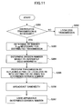
- Fig. 11 shows a flowchart of the distributed transmission method according to a second embodiment of the present invention.
- the division number of the resource block is adaptively determined according to the bandwidth to be used.
- multi-band communication communication is performed by choosing a bandwidth from among a plurality of bandwidths in order to provide optimal transmission condition according to services.
- a proper division number is selected according to the bandwidth used at transmission timing.
- step S201 the base station determines necessity of distributed transmission for each user in the cell.
- distributed transmission is unnecessary, localized transmission is performed (S202).
- the base station determines the number N DRB of total resource blocks to be assigned to the distributed transmission (S203).
- the base station determines the division number of the resource block based on the bandwidth which is being used at the current transmission timing simultaneously with step S203 or sequentially (s204).
- the base station replaces N DRB localized RBs with distributed RBs using a pattern according to the obtained division number, and transmits the blocks (S205).
- the base station reports the current frequency bandwidth using a broadcast channel (S206).
- the user apparatus determines the division number based on the reported bandwidth (S207).
- Fig. 12 is a block diagram of a base station apparatus 10B used in the second embodiment.
- the division number determination unit 13B includes a bandwidth-division number correspondence table 25.
- the bandwidth used by the base station 10B is input to the division number determination unit 13B and to the broadcast information generation unit 26 as information indicating current radio communication state.
- the division number determination unit 13B determines the current division number based on the bandwidth-division number correspondence table 25, and outputs the determined division number to the multiplexing unit 20.
- the broadcast information generation unit 26 generates a broadcast channel including bandwidth information.
- Fig. 13 shows an example of the bandwidth-division number correspondence table 25.
- 1.25 MHz, 5 MHz, 10 MHz and 20 MHz are provided as available bandwidths, and division numbers 2, 3, 3 and 3 are set respectively.
- the control information generation unit 19 generates a control channel based on L/D information, assigned RB number, transmission format and the line input from the scheduler 11, so as to perform channel coding and modulation.
- the multiplexing unit 20 maps (multiplexes), onto a frequency axis, the control channel, data channels for a plurality of users, and the broadcast channel onto a frequency axis.
- the multiplexing unit 20 includes a mapping pattern for mapping to physical resource blocks, so that the multiplexing unit 20 performs user multiplexing based on the division number supplied from the division number determination unit 13B.
- the multiplexed signal is modulated by inverse Fourier transform in the inverse fast Fourier transform unit 21. Then, a guard interval is added using a cyclic prefix scheme in the CP adding unit 22, and D/A conversion, RF conversion and band limitation and the like are performed by the RF transmission circuit 23. Then, transmission power is adjusted by the power amplifier 24, so that the signal is transmitted from the antenna.
- Fig. 14 shows a schematic block diagram of the user apparatus used in the second embodiment.
- the user apparatus 40 includes a broadcast channel demodulation unit 41, a control channel demodulation unit 42, a data demodulation/decoding unit 43, and a bandwidth-division number correspondence table 45.
- the broadcast channel demodulation unit 41 extracts a broadcast signal from a received signal which has been converted to a baseband signal, and demodulates the broadcast channel.
- the broadcast channel includes bandwidth information which is currently used.
- the division number is determined from the bandwidth-division number correspondence table 45 based on the broadcasted bandwidth information. In this sense, the correspondence table 45 functions as a division number determination unit.
- This correspondence table 45 has information similar to that in the correspondence table of the base station apparatus 10B. For example, the correspondence table 45 is similar to the table shown in Fig. 13 .
- the determined division number is input to the data demodulation unit 43.
- the control channel demodulation unit 42 extracts a control channel from the received signal which has been converted to the baseband signal, and demodulates the control channel, so that it is recognized that the user apparatus 40 is a target of the distributed transmission in the current TTI based on the L/D information.
- the control channel demodulation unit 42 demodulates the RB number assigned to the user apparatus 40 and transmission format information, and supply them to the data demodulation unit 43 with L/D information
- the data demodulation unit 43 extracts a downlink data channel addressed to the user apparatus from the received signal based on L/D information and assigned RB number received from the control information demodulation unit 42 and based on the division number received from the broadcast channel demodulation unit 41. Then, the data demodulation unit demodulates and decodes the data channel based on the transmission format information received from the control information demodulation unit 42, so as to output user data.
- mapping relationship between assigned RB number assigned by the base station and actual physical resource blocks is stored in a memory and the like which is not shown in the figure.
- the division number is adaptively changed according to the bandwidth which is being used.
- the bandwidth which is being used.
- transmission cannot be performed efficiently even if the division number is increased.
- the transmission efficiency can be improved as a whole.
Landscapes
- Engineering & Computer Science (AREA)
- Signal Processing (AREA)
- Computer Networks & Wireless Communication (AREA)
- Quality & Reliability (AREA)
- Mobile Radio Communication Systems (AREA)
Abstract
Description
- The present invention generally relates to a mobile communication technique. More particularly, the present invention relates to a radio communication control method including efficient transmission control of radio resources when performing distributed transmission in which data is transmitted while distributing the data by using divided resource blocks, and relates to configurations of a base station apparatus and a user apparatus.
- Demand for data services of higher speed and larger capacity is increasing as mobile terminals such as mobile phones become widespread and as multimedia expands. Especially, the orthogonal frequency division multiplexing (OFDM) scheme is considered to be a promising access scheme because demand for higher speed and larger capacity in the downlink is strong, and because efficient use of wide frequency bands is desired.
- In the OFDMA, band is divided into chunks called resource blocks (RB) so as to frequency-multiplex a plurality of users. As assignment/transmission schemes for resource blocks, two schemes which are a localized RB scheme and a distributed RB scheme are defined (refer to
non-patent document 1, for example). - In the localized RB scheme, contiguous bands are preferentially assigned to users in good channel state locally on a frequency axis. This scheme is advantageous for communication performed by a user of small mobility and is advantageous for high-quality and high-capacity data transmission and the like.
- In the distributed RB scheme, a downlink signal is generated and transmitted by distributing subdivided frequency components over a wideband. According to this scheme, frequency diversity can be expected, so that this scheme is advantageous for data transmission by a user of large mobility, and for periodical transmission of small-sized data like voice packets (VoIP).
- As shown in
Fig. 1 , in both of the localized RB scheme and the distributed RB scheme, each resource block assigned by the base station (cell) is specified by a resource block number (RB index). In the example shown inFig. 1 , in the localized RB scheme, if it is specified that a resource block of theRB number 2 is assigned, it is uniquely specified that resources of a physicalresource block number 2 are actually used. When the base station specifies that aRB number 2 is assigned in the distributed RB scheme, it is uniquely specified that the left half of the physicalresource block number 2 and the left half of the physicalresource block number 8 are used. A relative resource block number assigned by the base station may be called "virtual resource block number" in a sense of distinguishing from the actual physical resource block number. - In addition, as shown in
Fig. 2 , it is proposed to allow coexistence of both of the localized RB scheme and the distributed RB scheme according to situations of users (refer tonon-patent document 2, for example). When assignment and transmission of the distributed RB scheme become necessary for a user (for example, when starting high-speed movement), a part of localized RBs assigned by the base station is replaced with distributed RBs. Assuming that the number of resource blocks replaced by the distributed RBs is NDRB, positions used for distributed transmission are determined by a division number irrespective of NDRB. More particularly, a k-th block and a (k+6)-th block form a pair, and the pair is not changed irrespective of NDRS. - In the conventional method, when performing distributed transmission, the number (division number) of blocks into which one physical resource block is divided is determined in a fixed manner for each cell. The user apparatus recognizes mapping relationship between resource block numbers assigned by the base station in the distributed transmission and actual physical resource block positions, by using a broadcast channel and the like. In each user apparatus, after receiving, from the base station, a notification that the user apparatus is a target of distributed transmission in the current TTI, the user apparatus can receive, demodulate and decode a data channel at corresponding physical resource block positions based on the assigned virtual resource block numbers and the division number which is determined in a fixed manner.
- [Non-patent document 1] 3GPP, R1-062089, NTT DoCoMo, et al. "Comparison between RB-level and Subcarrier-level Distributed Transmission for Shared Data Channel in E-UTRA Downlink".
- [Non-patent document 2] 3GPP TSG RAN WG1 #49, Kobe, Japan, May 7-11, 2007, R1-072431, NTT DoCoMo, et al.
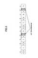
- When the division number is determined in a fixed manner as mentioned above, waste occurs if the number of total resource blocks assigned to a user in the distributed scheme is not an integral multiple of the division number of the resource block (in the above-mentioned example, since the resource block is divided into 2, the division number is 2). For examples, as shown in
Fig. 3 , in the case when the resource block number NDRB for distributed transmission (for example, resource assignment to a user moving at high speed) is 5 and the fixed division number is 2, the resource block cannot be divided into 2 for distribution unless 6 resource blocks are reserved by incrementing NDRB to 6. - In the example shown in
Fig. 3 , there is no data transmission in the right half of the physicalresource block number 4 and the right half of the physicalresource block number 10, so that efficiency decreases by one physical resource block. Similar waste continues to occur when NDRB changes to 3 or 9 as time passes. Such deterioration of the efficiency becomes remarkable when increasing the division number in order to obtain frequency diversity effects, because probability that NDRB becomes an integral multiple of the division number decreases. - In addition, in the case when a plurality of bandwidths can be used according to transmission conditions, if the division number is set to be fixed, there is a fear that transmission efficiency deteriorates when the bandwidth changes. The reason is as follows. When the bandwidth is large, frequency diversity effect can be easily realized by increasing the division number. But, data transmission efficiency deteriorates even by subdividing the resource blocks when the bandwidth is narrow.
- An object of the present invention is to provide a resource assignment control method which can eliminate resource waste and can maintain frequency diversity effect.
- In order to overcome the problem, the division number of one resource block is not fixed when performing distributed transmission, and the division number is adaptively (dynamically) changed according to the number NDRB of resource blocks of the distributed scheme or according to using bandwidth.
- In the configuration for adaptively changing the division number of the resource block when performing distributed transmission, the user apparatus needs to know the current division number in order to receive and decode a distributed-transmitted data channel addressed to the user apparatus at proper physical resource blocks. As methods for detecting the division number by the user apparatus, there are:
- (1) a method for reporting the division number from the base station to the user apparatus as control information at each transmission time interval TTI; and
- (2) a method for detecting the division number in a blind manner by the user apparatus.
- Further, as the method (1) for reporting division number, there are (1a) a method for reporting the division number as common control information by preparing a control channel field common to a plurality of users, and (1b) a method for preparing a field for reporting the division number in dedicated control information for each user. In the former case, every user apparatus to which distributed transmission is assigned decodes the field of the common control information necessarily.
- On the other hand, in the case in which the division number is changed according to the using bandwidth, as a method for ascertaining the current division number by the user apparatus, the division number is associated with each using bandwidth beforehand, so that both of the base station and the user apparatus recognizes the correspondence relationship, and the user apparatus determines the division number based on bandwidth information broadcasted from the base station.
- More particularly, according to a first aspect, the base station apparatus includes:
- a distributed transmission determination unit configured to determine a number (NDRB) of resource blocks to be used for data transmission of a distributed transmission scheme for a user apparatus at predetermined time interval; and
- a division number determination unit configured to variably determine a division number of one resource block according to the determined number of resource blocks of the distributed transmission scheme.
- According to a second aspect, the base station apparatus includes:
- a distributed transmission determination unit configured to determine a user apparatus which requires distributed transmission in which data is distributed using divided resource blocks for transmission; and
- a division number determination unit configured to variably determine a division number of one resource block according to a frequency bandwidth which is being used when there is the user apparatus which requires the distributed transmission.
- Each of base station apparatuses of the above-mentioned embodiments may be configured to further include a control information generation unit configured to generate control information for reporting the determined division number to one or more user apparatuses.
- In this case, the control information generation unit includes the division number into the control information as common control information common to the one or more user apparatuses. Or, the control information generation unit may be configured to include the division number into the control information as dedicated control information which is to be reported individually to each of the one or more user apparatuses.
- According to a third aspect, a configuration of a user apparatus is provided in the case when the division number is not reported. The user apparatus includes:
- a control information demodulation unit configured to demodulate control information indicating data transmission of a distributed scheme in which data is distributed using divided resource blocks;
- a plurality of data demodulation units provided according to a number of candidates of division number of the resource block which is adaptively selected for data transmission of the distributed scheme, each of the data demodulation units being configured to, when receiving the control information, extract and demodulate a data channel using a division number of a corresponding candidate; and
- a selecting unit configured to select a best demodulation result from among outputs of the plurality of data demodulation units, and output the result.
- According to a fourth aspect, a configuration of a user apparatus is provided in the case when the division number is changed according to the using bandwidth. The user apparatus includes:
- a control information demodulation unit configured to demodulate control information indicating data transmission of a distributed scheme in which data is distributed using divided resource blocks;
- a broadcast information demodulation unit configured to demodulate broadcast information indicating a current use bandwidth;
- a division number determination unit configured to determine a division number of the resource block based on the demodulated broadcast information; and
- a data demodulation unit configured to extract the data from a received signal based on the control information and the division number, and demodulate the data.
- According to a fifth aspect, a radio communication control method is provided for performing distributed transmission using a division number according to the number of resource blocks used for the distributed transmission. This method includes the steps of:
- determining a number (NDRB) of resource blocks to be transmitted using a distributed transmission scheme to one or more user apparatuses at predetermined time interval; and
- variably determining a division number of one resource block according to the determined number of distributed resource blocks.
- According to a sixth aspect, a radio communication control method is provided for performing distributed transmission using a division number according to the using bandwidth. This method includes the steps of:
- determining whether it is necessary to perform distributed transmission in which data is distributed using divided resource blocks for transmission for one or more user apparatuses; and
- variably determining a division number of one resource block according to a frequency bandwidth which is being used when it is determined that the distributed transmission is necessary.
- In either method, a step of generating control information for reporting the determined division number to the one or more user apparatuses may be included. In this case, the division number may be included into the control information as common control information common to the one or more user apparatuses, and the division number may be included into the control information as dedicated control information which is to be reported individually to each of the one or more user apparatuses.
- By adaptively changing the division number of the resource block when performing distributed transmission, wasted resources which causes no data transmission can be reduced as much as possible, so that data transmission efficiency improves.
-
-
Fig. 1 is a diagram showing assignment of resource blocks in the localized RB scheme and the distributed RB scheme; -
Fig. 2 is a diagram showing relationship between the number NDRB of resource blocks for distributed transmission and positions of the physical resource.blocks for distributed transmission; -
Fig. 3 is a diagram for explaining a problem in conventional setting of the division number in a fixed manner; -
Fig. 4 shows a flowchart of distributed transmission using the variable division number in the first embodiment; -
Fig. 5 is a schematic block diagram of a base station used in the first embodiment; -
Fig. 6 shows an example of a NDRB - division number correspondence table used in the base station shown inFig. 5 ; -
Fig. 7 is a diagram showing an example of distributed transmission using the variable division number according to the value of NDRB; -
Fig. 8A is a diagram showing an example of a reporting method of the division number from the base station to the user apparatus; -
Fig. 8B is a diagram showing an example of a reporting method of the division number from the base station to the user apparatus; -
Fig. 9A is a diagram showing an example of a reporting method of the division number from the base station to the user apparatus; -
Fig. 9B is a diagram showing an example of a reporting method of the division number from the base station to the user apparatus; -
Fig. 10 is a diagram showing a configuration example of a user apparatus which performs blind detection for detecting the division number in the first embodiment; -
Fig. 11 shows a flowchart of distributed transmission using the variable division number in the second embodiment; -
Fig. 12 is a schematic block diagram of a base station used in the second embodiment; -
Fig. 13 shows an example of a bandwidth - division number correspondence table used in the base station shown and the user apparatus of the second embodiment; and -
Fig. 14 is a diagram showing a configuration example of a user apparatus used in the second embodiment. -
- 10A, 10B
- base station apparatus
- 11
- scheduler
- 12
- NDRB determination unit (distributed transmission determination unit)
- 13A,
- 13B division number determination unit
- 15
- NDRB - division number correspondence table
- 17-1 - 17-n
- data generation processing unit
- 19
- control information generation processing unit
- 20
- multiplexing unit
- 25
- bandwidth - division number correspondence table
- 26
- broadcast information generation unit
- 30, 40
- user apparatus
- 31
- control information demodulation unit
- 32-1, 32-2
- data demodulation unit
- 33-1, 33-2
- error detection unit
- 34
- selecting unit
- 41
- broadcast channel demodulation unit
- 42
- control channel demodulation unit
- 43
- data demodulation/decoding unit
- 45
- bandwidth - division number correspondence table (division number determination unit)
- 51
- common control information field
- 52-1 - 52-3
- dedicated control information field
- 53-1 - 53-2
- dedicated division number field
- In the following, preferred embodiments of the present invention are described with reference to figures.
-
Fig. 4 is a flowchart of the distribute transmission method according to the first embodiment of the present invention. In the first embodiment, the division number of the resource block is adaptively determined according to the number NDRB of resource blocks to be used for distributed transmission. - First, in step S101, necessity of distributed transmission is determined at a TTI of transmission timing. The determination is performed in the base station for each user apparatus in a cell based on the communication quality (SINR etc.), moving speed, QoS and the like. For example, when the moving speed of the user apparatus exceeds a predetermined speed, or when voice communication is performed, distributed transmission is determined to be necessary. When mobility is small, or when there are only users who transmit large capacity data with high quality, distributed transmission is determined to be unnecessary.
- When the distributed transmission is unnecessary, localized transmission is performed (S102). When the distributed transmission is necessary, the number NDRB (to be referred to as "distributed RB number") of total resource blocks assigned to the distributed transmission is determined (S103). NDRB is a sum total of resource block sizes (numbers) necessary for data transmission of target users of the distributed transmission. By the way, for a user who requires a plurality of resource blocks for data transmission, separated physical resource blocks can be assigned without dividing the resource block while maintaining the state of localized RB. Therefore, users targeted for the distributed transmission can be limited to users requiring assignment of only one resource block. But, from the viewpoint of enhancing frequency diversity effect, a user requiring assignment of more than one resource block can be determined to be a target user for the distributed transmission.
- When the distributed RB number NDRB is determined, the division number of the resource block is determined according to the value (S104). The division number can be obtained by storing necessary correspondence relationship between the distributed RB number NDRB and the division number in the base station beforehand. In this case, for example, NDRB is associated with the division number such that the division number is 2 when NDRB is 2, the division number is 3 when NDRB is 3, and the division number is 2 when NDRB is 4, and the like. Then, the number NDRB of localized RBs are replaced with distributed RBs based on a pattern according to the obtained division number, so that the distributed RBs are transmitted (S105).
- The base station reports the division number to the user apparatus using a control channel, or instead of reporting the division number, the division number is detected by the user apparatus by performing blind detection (S106). The method for reporting the division number is described later.
-
Fig. 5 is a schematic block diagram of thebase station apparatus 10A used in the first embodiment. Thebase station apparatus 10A includes ascheduler 11, a divisionnumber determination unit 13A, data generation processing units 17-1 - 17-n for each user, a control informationgeneration processing unit 19, and amultiplexing unit 20. Thescheduler 11 receives transmission data addressed to each user apparatus from a buffer which is not shown in the figure, and thescheduler 11 receives user apparatus information such as user quality (SINR etc.), requested service quality QoS, moving speed fD and the like which have been received in the uplink and demodulated. - The distributed RB number (NDRB)
determination unit 12 determines whether there is a user requiring distributed transmission in a current TTI based on the received user apparatus information. If there is such a user, the distributed RB number (NDRB)determination unit 12 determines the total resource block number NDRB used for the distributed transmission. When there is no user requiring the distributed transmission, NDRB=0. In this since, the NDRB number determination unit can be more broadly called as "distributed transmission determination unit". The determined NDRB is input to the divisionnumber determination unit 13A as a parameter representing a radio communication state in the current TTI. - The division
number determination unit 13A determines the division number according to NDRB based on a NDRB-division number correspondence table 15, and outputs the determined division number to the controlinformation generation unit 19 and the multiplexingunit 20.Fig. 6 shows an example of the NDRB-division number correspondence table 15. In this example, the resource block is divided into 2 when NDRB is 2 and 4, and the resource block is divided into 3 when NDRB is 3, 5 and 6. - The
scheduler 11 determines which resource block and what kind of transmission scheme are used for transmitting a data channel for each of user apparatuses (which include a user apparatus of a target of distributed transmission and a user apparatus of a target of localized transmission), and thescheduler 11 provides the determined information to the control informationgeneration processing unit 19. The input information to the controlinformation generation unit 19 includes information (L/D information) indicating whether a user is a target of distributed transmission or a target of localized transmission, assigned resource block numbers, transmission format, and the like. - Each data
generation processing unit 17 generates a data signal with a resource block size (number) determined by thescheduler 11, and performs channel coding and data modulation using a predetermined coding rate and modulation scheme, for each corresponding user apparatus. - The control information
generation processing unit 19 generates a control channel based on the L/D information of each user, assigned RB number and transmission format information received from thescheduler 11 and based on the division number information received from the divisionnumber determination unit 13A. Then, the control informationgeneration processing unit 19 performs channel coding and modulation for the control channel. - The multiplexing
unit 20 maps (multiplexes), onto a frequency axis, a control channel, data channels for a plurality of users, and other physical channels (not shown in the figure) as necessary. The multiplexingunit 20 includes a pattern for mapping into physical resource blocks, so that the multiplexingunit 20 performs user multiplexing based on the division number supplied from the divisionnumber determination unit 13A. The multiplexed signal is modulated by inverse Fourier transform in the inverse fastFourier transform unit 21. Then, a guard interval is added using a cyclic prefix scheme in theCP adding unit 22, and, D/A conversion, RF conversion and band limitation and the like are performed by theRF transmission circuit 23. Then, transmission power is adjusted by thepower amplifier 24, so that the signal is transmitted from the antenna. - In the example shown in
Fig. 5 , although thescheduler 11 and the divisionnumber determination unit 13A are separated, the divisionnumber determination unit 13A may be embedded into thescheduler 11 as a unit. -
Fig. 7 is a diagram showing an example of distributed transmission based on variable division number according to the value of NDRB. When NDRB=2 and NDRB=4, the resource (frequency) is distributed by dividing into 2 for transmission. When NDRB=3, 5 and 6, the resource (frequency) is distributed by dividing into 3. Although not shown in the figure, when NDRB=8, the resource may be divided into 2. But, when sufficient bandwidth is provided, high frequency diversity effect can be achieved by dividing the resource into 4. - When NDRB=5, data is not transmitted in the shaded area (assigned resource block number 10) so that waste of one physical resource block occurs. But, this situation is limited only to the case when the number of resource blocks for the distributed transmission is 5 in a TTI. If the number is changed to NDRB=4, the division number is also changed to 2 according to the change, so that the waste is eliminated. Therefore, compared to the conventional method in which 2-block division or 3-block division is set in a fixed manner, the transmission efficiency is remarkable improved.
-
Fig. 8A shows a first reporting method (1a) for reporting the division number to the user apparatus from thebase station apparatus 10A in each TTI. In the first reporting method, afield 51 which is common to user apparatuses which are targets of the distributed transmission is prepared in a control channel. Every use apparatus which is the target of the distributed transmission demodulates thefield 51 for this common control information. Information indicating whether a user apparatus is a target of the distributed transmission is inserted into dedicated control information fields 52-1, 52-2 and 52-3 for UE1, UE2 and UE3 respectively. For example, by providing one bit area in the field 52 for each user apparatus, information (L/D) indicating whether to apply distributed transmission or localized transmission is embedded into the one bit area. Such control channel is generated by the control informationgeneration processing unit 19. - In the example of
Fig. 8A , distributed transmission is performed for the user apparatuses UE1 and UE2, and localized transmission is performed for UE3. As shown inFig. 8B , the user apparatus UE1 recognizes that assignment has been performed for UE1 since the control channel includes the field UE1 (52-1) corresponding to the ID number of UE1. Then, the user apparatus UE1 extracts L/D information and assigned resource block number form the dedicated control information field 52-1. In addition to that, the dedicated control information field 52-1 includes control information such as modulation method and channel coding rate and the like. - After the user apparatus UE1 detects that the user apparatus UE1 is a target of the distributed transmission by the L/D information, the user apparatus UE1 demodulates the common
control information field 51 so as to recognize the division number in the current TTI. Similarly, the user apparatus UE2 recognizes that the user apparatus UE2 is a target of the distributed transmission based on the control information field 52-2, and demodulates the commoncontrol information field 51. On the other hand, the user apparatus UE3 detects that it is a target of the localized transmission, and the user apparatus UE3 does not demodulate the commoncontrol information field 51. -
Fig. 9A shows a second reporting method (1a) for reporting the division number in each TTI from thebase station apparatus 10A to the user apparatus. In the second reporting method, a dedicated field 53 indicating the division number is provided for each user apparatus which is the target of the distributed transmission. In this example, as shown inFig. 9B , the use apparatuses UE1 and UE2 are provided with dedicated division number fields 53-1 and 53-2 addressed to the respective apparatuses. Thus, each of the user apparatuses recognizes that it is a target of the distributed transmission, so that the user apparatuses can receive and demodulate data at distributed proper positions in actual physical resource blocks by using the resource block numbers included in the dedicated control information fields 52-1 and 52-2, and the division number in the current TTI included in the division number fields 53-1 and 53-2. Since there is no dedicated division number field for the user apparatus UE3, the user apparatus UE3 recognizes that localized transmission is performed, and receives and demodulates user data at actual positions of the physical resource blocks specified from the assigned resource block numbers. -
Fig. 10 shows a configuration example of theuser apparatus 30 when the user apparatus detects the division number in a blind manner. In this case, the base station transmits, to each user apparatus, control information such as information indicating that distributed transmission is performed, assigned RB number, modulation method and channel coding rate and the like without reporting the division number. Therefore, in this case, in the configuration ofFig. 5 , the input line from the divisionnumber determination unit 13A to the control informationgeneration processing unit 19 is not provided. - The
user apparatus 30 includes a controlchannel demodulation unit 31 and data demodulation units 32-1,32-2, ... according to the number of division number candidates to be used. For example, assuming that the division number is adaptively changed between 2 and 3 (2-block division and 3-block division) in the system of the present invention, a data demodulation unit 1 (32-1) and a data demodulation unit 2 (32-2) are provided since the number of division number candidates is 2. By the way, when theuser apparatus 30 is a target of the localized transmission in the current TTI, only a single data demodulation unit 32 is used. In the present embodiment, processing when the user apparatus is a target of the distributed transmission is described. - The control
information demodulation unit 31 extracts the control channel from a received signal which has been converted to a base band signal, and demodulates the control channel, so that it is recognized that theuser apparatus 30 is a target of the distributed transmission in a current TTI. Further, the controlinformation demodulation unit 31 demodulates the RB number assigned to theuser apparatus 30 and transmission format information, and provides each pieces of the information to each of the data demodulation units 32-1 and 32-2 with L/D information. - The first data demodulation unit 32-1 extracts, from the received signal, a downlink data channel addressed to the user apparatus based on the assigned RB number and a first division number candidate (
division number 2, for example) received from the controlinformation demodulation unit 31, and the first data demodulation unit 32-1 demodulates the data channel based on the transmission format information received from the controlinformation demodulation unit 31. The first error detection unit 33-1 performs error detection on the data channel which is de-mapped based on thedivision number 2. By the way, theuser apparatus 30 stores mapping relationship between assigned RB number assigned by thebase station apparatus 10A and actual physical resource block number in a memory and the like which is not shown in the figure. - The second data demodulation unit 32-2 extracts, from the received signal, the downlink data channel addressed to the user apparatus based on the assigned RB number and a second division number candidate (
division number 3, for example) received from the controlinformation demodulation unit 31, and the second data demodulation unit 32-2 demodulates the data channel based on the transmission format information received from the controlinformation demodulation unit 31. The second error detection unit 33-2 performs error detection on the data channel which is de-mapped based on thedivision number 3. - Outputs of the first and the second detection units 33-1 and 33-2 are connected to inputs of the selecting
unit 34. The selectingunit 34 selects one having fewer errors and outputs the selected one. Although two of 2-block division and 3-block division are used as a range of division number variable control in the example shown inFig. 10 , when 4-block division is included in the range of the variable control, a third demodulation unit and a third error detection unit are further used. - Accordingly, in the first embodiment, the number NDRB of resource blocks which require distributed transmission in a TTI is obtained according to state of users in a cell, so that a division number is determined according to the value of NDRB, and distributed transmission is performed. Therefore, deterioration of resource efficiency can be decreased largely.
-
Fig. 11 shows a flowchart of the distributed transmission method according to a second embodiment of the present invention. In the second embodiment, the division number of the resource block is adaptively determined according to the bandwidth to be used. - In multi-band communication, communication is performed by choosing a bandwidth from among a plurality of bandwidths in order to provide optimal transmission condition according to services. Thus, when performing distributed transmission, a proper division number is selected according to the bandwidth used at transmission timing.
- First, in step S201, the base station determines necessity of distributed transmission for each user in the cell. When distributed transmission is unnecessary, localized transmission is performed (S202). When distributed transmission is necessary, the base station determines the number NDRB of total resource blocks to be assigned to the distributed transmission (S203). Then, the base station determines the division number of the resource block based on the bandwidth which is being used at the current transmission timing simultaneously with step S203 or sequentially (s204). The base station replaces NDRB localized RBs with distributed RBs using a pattern according to the obtained division number, and transmits the blocks (S205).
- The base station reports the current frequency bandwidth using a broadcast channel (S206). The user apparatus determines the division number based on the reported bandwidth (S207).
-
Fig. 12 is a block diagram of abase station apparatus 10B used in the second embodiment. In the second embodiment, the divisionnumber determination unit 13B includes a bandwidth-division number correspondence table 25. The bandwidth used by thebase station 10B is input to the divisionnumber determination unit 13B and to the broadcastinformation generation unit 26 as information indicating current radio communication state. The divisionnumber determination unit 13B determines the current division number based on the bandwidth-division number correspondence table 25, and outputs the determined division number to themultiplexing unit 20. The broadcastinformation generation unit 26 generates a broadcast channel including bandwidth information. -
Fig. 13 shows an example of the bandwidth-division number correspondence table 25. For example, 1.25 MHz, 5 MHz, 10 MHz and 20 MHz are provided as available bandwidths, anddivision numbers - The control
information generation unit 19 generates a control channel based on L/D information, assigned RB number, transmission format and the line input from thescheduler 11, so as to perform channel coding and modulation. - The multiplexing
unit 20 maps (multiplexes), onto a frequency axis, the control channel, data channels for a plurality of users, and the broadcast channel onto a frequency axis. The multiplexingunit 20 includes a mapping pattern for mapping to physical resource blocks, so that the multiplexingunit 20 performs user multiplexing based on the division number supplied from the divisionnumber determination unit 13B. The multiplexed signal is modulated by inverse Fourier transform in the inverse fastFourier transform unit 21. Then, a guard interval is added using a cyclic prefix scheme in theCP adding unit 22, and D/A conversion, RF conversion and band limitation and the like are performed by theRF transmission circuit 23. Then, transmission power is adjusted by thepower amplifier 24, so that the signal is transmitted from the antenna. -
Fig. 14 shows a schematic block diagram of the user apparatus used in the second embodiment. Theuser apparatus 40 includes a broadcastchannel demodulation unit 41, a controlchannel demodulation unit 42, a data demodulation/decoding unit 43, and a bandwidth-division number correspondence table 45. - The broadcast
channel demodulation unit 41 extracts a broadcast signal from a received signal which has been converted to a baseband signal, and demodulates the broadcast channel. The broadcast channel includes bandwidth information which is currently used. The division number is determined from the bandwidth-division number correspondence table 45 based on the broadcasted bandwidth information. In this sense, the correspondence table 45 functions as a division number determination unit. This correspondence table 45 has information similar to that in the correspondence table of thebase station apparatus 10B. For example, the correspondence table 45 is similar to the table shown inFig. 13 . The determined division number is input to thedata demodulation unit 43. - The control
channel demodulation unit 42 extracts a control channel from the received signal which has been converted to the baseband signal, and demodulates the control channel, so that it is recognized that theuser apparatus 40 is a target of the distributed transmission in the current TTI based on the L/D information. In addition, the controlchannel demodulation unit 42 demodulates the RB number assigned to theuser apparatus 40 and transmission format information, and supply them to thedata demodulation unit 43 with L/D information - The
data demodulation unit 43 extracts a downlink data channel addressed to the user apparatus from the received signal based on L/D information and assigned RB number received from the controlinformation demodulation unit 42 and based on the division number received from the broadcastchannel demodulation unit 41. Then, the data demodulation unit demodulates and decodes the data channel based on the transmission format information received from the controlinformation demodulation unit 42, so as to output user data. By the way, mapping relationship between assigned RB number assigned by the base station and actual physical resource blocks is stored in a memory and the like which is not shown in the figure. - Accordingly, in the second embodiment, the division number is adaptively changed according to the bandwidth which is being used. When a narrow bandwidth is used, transmission cannot be performed efficiently even if the division number is increased. Thus, by adaptively changing the division number according to the bandwidth, the transmission efficiency can be improved as a whole.
- The present international application claims priority based on Japanese patent application No.
2007-161949 2007-161949
Claims (18)
- A base station apparatus comprising:a distributed transmission determination unit configured to determine a number (NDRB) of resource blocks to be used for data transmission of a distributed transmission scheme for a user apparatus at predetermined time interval; anda division number determination unit configured to variably determine a division number of one resource block according to the determined number of resource blocks of the distributed transmission scheme.
- A base station apparatus comprising:a distributed transmission determination unit configured to determine a user apparatus which requires distributed transmission in which data is distributed using divided resource blocks for transmission; anda division number determination unit configured to variably determine a division number of one resource block according to a frequency bandwidth which is being used when there is the user apparatus which requires the distributed transmission.
- The base station apparatus as claimed in claim 1 or 2, further comprising:a control information generation unit configured to generate control information for reporting the determined division number to one or more user apparatuses.
- The base station apparatus as claimed in claim 3, wherein the control information generation unit includes the division number into the control information as common control information common to the one or more user apparatuses.
- The base station apparatus as claimed in claim 3, wherein the control information generation unit includes the division number into the control information as dedicated control information which is to be reported individually to each of the one or more user apparatuses.
- The base station apparatus as claimed in claim 1, wherein the division number determination unit includes a correspondence table in which an arbitrary number of distributed resource blocks is associated with the division number beforehand.
- The base station apparatus as claimed in claim 2, wherein the division number determination unit includes a correspondence table in which frequency bandwidth which is usable in the base station is associated with the division number beforehand.
- A user apparatus comprising:a control information demodulation unit configured to demodulate control information indicating data transmission of a distributed scheme in which data is distributed using divided resource blocks;a plurality of data demodulation units provided according to a number of candidates of division number of the resource block which is adaptively selected for data transmission of the distributed scheme, each of the data demodulation units being configured to, when receiving the control information, extract and demodulate a data channel using a division number of a corresponding candidate; anda selecting unit configured to select a best demodulation result from among outputs of the plurality of data demodulation units, and output the result.
- A user apparatus comprising:a control information demodulation unit configured to demodulate control information indicating data transmission of a distributed scheme in which data is distributed using divided resource blocks;a broadcast information demodulation unit configured to demodulate broadcast information indicating a current use bandwidth;a division number determination unit configured to determine a division number of the resource block based on the demodulated broadcast information; anda data demodulation unit configured to extract the data from a received signal based on the control information and the division number, and demodulate the data.
- A radio communication control method comprising the steps of:determining a number (NDRB) of resource blocks to be transmitted using a distributed transmission scheme to one or more user apparatuses at predetermined time interval; andvariably determining a division number of one resource block according to the determined number of distributed resource blocks.
- A radio communication control method comprising the steps of:determining whether it is necessary to perform distributed transmission in which data is distributed using divided resource blocks for transmission for one or more user apparatuses; andvariably determining a division number of one resource block according to a frequency bandwidth which is being used when it is determined that the distributed transmission is necessary.
- The radio communication control method as claimed in claim 10 or 11, further comprising:a step of generating control information for reporting the determined division number to the one or more user apparatuses.
- The radio communication control method as claimed in claim 12, wherein the control information generation step includes the division number into the control information as common control information common to the one or more user apparatuses.
- The radio communication control method as claimed in claim 12, wherein the control information generation step includes the division number into the control information as dedicated control information which is to be reported individually to each of the one or more user apparatuses.
- The radio communication control method as claimed in claim 10, wherein the division number is determined based on predetermined correspondence relationship between an arbitrary number of distributed resource blocks and the division number.
- The radio communication control method as claimed in claim 11, wherein the division number is determined based on predetermined correspondence relationship between available frequency bandwidth and the division number.
- The radio communication control method as claimed in claim 10, further comprising the steps of:transmitting control information indicating that the distributed transmission is performed to the one or more user apparatuses; anddetecting the division number using a blind scheme when the one or more user apparatuses receive the control information.
- The radio communication control method as claimed in claim 11, further comprising the steps of:transmitting control information indicating that the distributed transmission is performed to the one or more user apparatuses;broadcasting frequency bandwidth which is used; anddetermining the division number of the resource block based on the broadcasted frequency bandwidth when the one or more user apparatuses receive the control information.
Applications Claiming Priority (2)
| Application Number | Priority Date | Filing Date | Title |
|---|---|---|---|
| JP2007161949A JP4916389B2 (en) | 2007-06-19 | 2007-06-19 | Wireless communication control method, base station apparatus, and user apparatus |
| PCT/JP2008/060998 WO2008156062A1 (en) | 2007-06-19 | 2008-06-16 | Radio communication control method, base station device, and user device |
Publications (2)
| Publication Number | Publication Date |
|---|---|
| EP2169862A1 true EP2169862A1 (en) | 2010-03-31 |
| EP2169862A4 EP2169862A4 (en) | 2014-06-25 |
Family
ID=40156221
Family Applications (1)
| Application Number | Title | Priority Date | Filing Date |
|---|---|---|---|
| EP08765681.5A Withdrawn EP2169862A4 (en) | 2007-06-19 | 2008-06-16 | RADIO COMMUNICATION CONTROL METHOD, BASE STATION DEVICE, AND USER DEVICE |
Country Status (6)
| Country | Link |
|---|---|
| US (1) | US8311550B2 (en) |
| EP (1) | EP2169862A4 (en) |
| JP (1) | JP4916389B2 (en) |
| KR (1) | KR20100024487A (en) |
| CN (1) | CN101779510B (en) |
| WO (1) | WO2008156062A1 (en) |
Cited By (1)
| Publication number | Priority date | Publication date | Assignee | Title |
|---|---|---|---|---|
| WO2012150833A3 (en) * | 2011-05-03 | 2013-03-21 | Samsung Electronics Co., Ltd. | Method and system for computing layer 2 load conditions in a wireless network environment |
Families Citing this family (21)
| Publication number | Priority date | Publication date | Assignee | Title |
|---|---|---|---|---|
| JP3860556B2 (en) | 2003-04-04 | 2006-12-20 | 松下電器産業株式会社 | Base station apparatus and communication method |
| US9125068B2 (en) | 2010-06-04 | 2015-09-01 | Ixia | Methods, systems, and computer readable media for simulating realistic movement of user equipment in a long term evolution (LTE) network |
| US8855070B2 (en) | 2011-12-14 | 2014-10-07 | Ixia | Methods, systems, and computer readable media for improved long term evolution (LTE) hybrid automatic repeat request (HARQ) processing |
| US9154979B2 (en) | 2011-12-14 | 2015-10-06 | Ixia | Scalable architecture for long term evolution (LTE) multiple user equipment (multi-UE) simulation |
| US9204325B2 (en) | 2011-12-20 | 2015-12-01 | Ixia | Methods, systems, and computer readable media for reducing the impact of false downlink control information (DCI) detection in long term evolution (LTE) physical downlink control channel (PDCCH) data |
| US9071995B2 (en) | 2012-01-17 | 2015-06-30 | Ixia | Methods, systems, and computer readable media for long term evolution (LTE) uplink data processing |
| US8908535B2 (en) | 2012-02-10 | 2014-12-09 | Ixia | Methods, traffic simulators, and computer readable media for validating long term evolution (LTE) code blocks and transport blocks |
| US8724498B2 (en) * | 2012-02-14 | 2014-05-13 | Ixia | Methods, systems, and computer readable media for performing long term evolution (LTE) channel delineation |
| US8892829B2 (en) | 2012-02-29 | 2014-11-18 | Ixia | Methods, systems, and computer readable media for integrated sub-block interleaving and rate matching |
| EP3065494A1 (en) * | 2012-02-29 | 2016-09-07 | Kyocera Corporation | Mobile communication system, mobile communication method, and radio base station |
| US8738985B2 (en) | 2012-03-28 | 2014-05-27 | Ixia | Methods, systems, and computer readable media for dynamically controlling a turbo decoding process in a long term evolution (LTE) multi-user equipment (UE) traffic simulator |
| US9131000B2 (en) | 2012-04-13 | 2015-09-08 | Ixia | Methods, systems, and computer readable media for heuristics-based adaptive protocol parsing |
| CN107484159B (en) * | 2012-07-24 | 2023-04-11 | 华为技术有限公司 | Counter checking method and device |
| WO2014043922A1 (en) * | 2012-09-24 | 2014-03-27 | 华为技术有限公司 | Method, base station and user equipment for transmitting broadcast message |
| US9801191B2 (en) * | 2013-01-18 | 2017-10-24 | Lg Electronics Inc. | Resource allocation method for supporting interference removal, and serving cell base station |
| US9198065B2 (en) | 2013-03-15 | 2015-11-24 | Ixia | Methods, systems, and computer readable media for utilizing adaptive symbol processing in a multiple user equipment (multi-UE) simulator |
| WO2015022736A1 (en) * | 2013-08-14 | 2015-02-19 | 富士通株式会社 | Communication system, base station, radio devices, and communication method |
| US9577669B2 (en) | 2014-11-03 | 2017-02-21 | Ixia | Methods, systems, and computer readable media for optimized message decoding |
| US9807204B2 (en) | 2015-03-06 | 2017-10-31 | Ixia | Optimized message processing |
| US10341066B2 (en) | 2017-08-03 | 2019-07-02 | Samsung Electronics Co., Ltd. | System and method for common phase error and inter-carrier interference estimation and compensation |
| US11088744B1 (en) | 2020-02-07 | 2021-08-10 | Keysight Technologies, Inc. | Methods, systems, and computer readable media for 5G digital beamforming testing |
Family Cites Families (26)
| Publication number | Priority date | Publication date | Assignee | Title |
|---|---|---|---|---|
| US6760882B1 (en) * | 2000-09-19 | 2004-07-06 | Intel Corporation | Mode selection for data transmission in wireless communication channels based on statistical parameters |
| MXPA03005307A (en) * | 2000-12-15 | 2004-12-02 | Adaptix Inc | Multi-carrier communications with group-based subcarrier allocation. |
| US7346037B2 (en) * | 2001-03-26 | 2008-03-18 | Lg Electronics Inc. | Method of transmitting or receiving a data packet in packet data communication system using hybrid automatic repeat request |
| US6912240B2 (en) * | 2001-11-26 | 2005-06-28 | Time Domain Corporation | Method and apparatus for generating a large number of codes having desirable correlation properties |
| KR100560386B1 (en) * | 2003-12-17 | 2006-03-13 | 한국전자통신연구원 | Transmitter and Method of Orthogonal Frequency Division Multiple Access for Coherent Detection in Uplink of Wireless Communication System |
| US8031583B2 (en) * | 2005-03-30 | 2011-10-04 | Motorola Mobility, Inc. | Method and apparatus for reducing round trip latency and overhead within a communication system |
| KR100724949B1 (en) * | 2005-05-03 | 2007-06-04 | 삼성전자주식회사 | Method and apparatus for multiplexing data and control information in frequency division multiple access based wireless communication system |
| US8594207B2 (en) * | 2005-10-31 | 2013-11-26 | Motorola Mobility Llc | Method and apparatus for providing channel quality feedback in an orthogonal frequency division multiplexing communication system |
| TW200733622A (en) * | 2006-01-17 | 2007-09-01 | Interdigital Tech Corp | Method and apparatus for mapping an uplink control channel to a physical channel in a single carrier frequency division multiple access system |
| JP4343926B2 (en) | 2006-02-08 | 2009-10-14 | 株式会社エヌ・ティ・ティ・ドコモ | Transmitting apparatus and transmitting method |
| US20070217362A1 (en) * | 2006-03-20 | 2007-09-20 | Nokia Corporation | Amended control for resource allocation in a radio access network |
| US8131306B2 (en) * | 2006-03-20 | 2012-03-06 | Intel Corporation | Wireless access network and method for allocating data subcarriers within a downlink subframe based on grouping of user stations |
| US10044532B2 (en) * | 2006-03-20 | 2018-08-07 | Texas Instruments Incorporated | Pre-coder selection based on resource block grouping |
| EP1990942A1 (en) * | 2006-03-20 | 2008-11-12 | Matsushita Electric Industrial Co., Ltd. | Radio communication system, radio transmission device, and retransmission method |
| US8102802B2 (en) * | 2006-05-08 | 2012-01-24 | Motorola Mobility, Inc. | Method and apparatus for providing downlink acknowledgments and transmit indicators in an orthogonal frequency division multiplexing communication system |
| KR101284836B1 (en) * | 2006-05-25 | 2013-07-10 | 삼성전자주식회사 | Constructing method of resource assignment map for mobile communication systems |
| US8150410B2 (en) * | 2006-06-16 | 2012-04-03 | Samsung Electronics Co., Ltd. | System and method for a fractional loading scheme for broadcast/multicast traffic |
| US7720470B2 (en) * | 2006-06-19 | 2010-05-18 | Intel Corporation | Reference signals for downlink beamforming validation in wireless multicarrier MIMO channel |
| JPWO2008001728A1 (en) * | 2006-06-26 | 2009-11-26 | パナソニック株式会社 | Radio communication base station apparatus and resource block allocation method |
| JP4295300B2 (en) * | 2006-08-22 | 2009-07-15 | 株式会社エヌ・ティ・ティ・ドコモ | Transmitting apparatus and transmitting method |
| JP5006001B2 (en) * | 2006-08-22 | 2012-08-22 | 株式会社エヌ・ティ・ティ・ドコモ | Downlink MIMO transmission control method and base station apparatus |
| US8073062B2 (en) * | 2007-02-08 | 2011-12-06 | Motorola Mobility, Inc. | Method and apparatus for downlink resource allocation in an orthogonal frequency division multiplexing communication system |
| EP2159938A4 (en) * | 2007-06-18 | 2013-09-18 | Mitsubishi Electric Corp | COMMUNICATION METHOD, WIRELESS COMMUNICATION SYSTEM, TRANSMITTER AND RECEIVER |
| US7907677B2 (en) * | 2007-08-10 | 2011-03-15 | Intel Corporation | Open loop MU-MIMO |
| KR100904433B1 (en) * | 2008-01-07 | 2009-06-24 | 엘지전자 주식회사 | Distributed Virtual Resource Block Scheduling Method |
| KR100925441B1 (en) * | 2008-01-07 | 2009-11-06 | 엘지전자 주식회사 | Distributed Virtual Resource Block Scheduling Method |
-
2007
- 2007-06-19 JP JP2007161949A patent/JP4916389B2/en not_active Expired - Fee Related
-
2008
- 2008-06-16 CN CN200880103100XA patent/CN101779510B/en not_active Expired - Fee Related
- 2008-06-16 WO PCT/JP2008/060998 patent/WO2008156062A1/en not_active Ceased
- 2008-06-16 EP EP08765681.5A patent/EP2169862A4/en not_active Withdrawn
- 2008-06-16 KR KR1020107000710A patent/KR20100024487A/en not_active Ceased
- 2008-06-16 US US12/665,362 patent/US8311550B2/en not_active Expired - Fee Related
Non-Patent Citations (4)
| Title |
|---|
| NTT DOCOMO ET AL: "Comparison between RB-level and Sub-carrier-level Distributed Transmission for Shared Data Channel in E-UTRA Downlink", 3GPP DRAFT; R1-071115 DL COMPARISON ON DISTRIBUTED TRANSMISSION, 3RD GENERATION PARTNERSHIP PROJECT (3GPP), MOBILE COMPETENCE CENTRE ; 650, ROUTE DES LUCIOLES ; F-06921 SOPHIA-ANTIPOLIS CEDEX ; FRANCE, vol. RAN WG1, no. St. Louis, USA; 20070207, 7 February 2007 (2007-02-07), XP050105106, [retrieved on 2007-02-07] * |
| NTT DOCOMO ET AL: "Distributed OFDMA Transmission for Shared Data Channel in E-UTRA Downlink", 3GPP DRAFT; R1-060038 DL SHARED DATA CHANNEL, 3RD GENERATION PARTNERSHIP PROJECT (3GPP), MOBILE COMPETENCE CENTRE ; 650, ROUTE DES LUCIOLES ; F-06921 SOPHIA-ANTIPOLIS CEDEX ; FRANCE, vol. RAN WG1, no. Helsinki, Finland; 20060123, 19 January 2006 (2006-01-19), XP050417425, [retrieved on 2006-01-19] * |
| NTT DOCOMO ET AL: "L1/L2 Control Channel Structure for E-UTRA Downlink", 3GPP DRAFT; R1-060032 DL L1L2 CONTROL CHANNEL, 3RD GENERATION PARTNERSHIP PROJECT (3GPP), MOBILE COMPETENCE CENTRE ; 650, ROUTE DES LUCIOLES ; F-06921 SOPHIA-ANTIPOLIS CEDEX ; FRANCE, vol. RAN WG1, no. Helsinki, Finland; 20060119, 19 January 2006 (2006-01-19), XP050111175, [retrieved on 2006-01-19] * |
| See also references of WO2008156062A1 * |
Cited By (2)
| Publication number | Priority date | Publication date | Assignee | Title |
|---|---|---|---|---|
| WO2012150833A3 (en) * | 2011-05-03 | 2013-03-21 | Samsung Electronics Co., Ltd. | Method and system for computing layer 2 load conditions in a wireless network environment |
| US9615275B2 (en) | 2011-05-03 | 2017-04-04 | Samsung Electronics Co., Ltd. | Method and apparatus for computing layer 2 load conditions in a wireless network environment |
Also Published As
| Publication number | Publication date |
|---|---|
| US8311550B2 (en) | 2012-11-13 |
| JP4916389B2 (en) | 2012-04-11 |
| WO2008156062A1 (en) | 2008-12-24 |
| JP2009004923A (en) | 2009-01-08 |
| CN101779510A (en) | 2010-07-14 |
| US20100184447A1 (en) | 2010-07-22 |
| EP2169862A4 (en) | 2014-06-25 |
| KR20100024487A (en) | 2010-03-05 |
| CN101779510B (en) | 2013-06-12 |
Similar Documents
| Publication | Publication Date | Title |
|---|---|---|
| US8311550B2 (en) | Radio communication control method, base station apparatus and user apparatus | |
| CN101223720B (en) | Sending device, sending method, receiving device and receiving method | |
| US8243839B2 (en) | Base station, mobile station and method | |
| KR101215346B1 (en) | Mobile station base station and method | |
| US7983236B2 (en) | Pilot structure for multicarrier transmissions | |
| JP5512757B2 (en) | Uplink pilot multiplexing in single user MIMO and SDMA for single carrier frequency division multiple access systems | |
| JP4510077B2 (en) | Apparatus and method for generating preamble sequence for adaptive antenna system in orthogonal frequency division multiple access communication system | |
| CN102415180B (en) | Mobile terminal device and radio communication method | |
| US20090219910A1 (en) | Method for transmitting and receiving signals using multi-band radio frequencies | |
| CN101406077A (en) | Transmitting device, and transmitting method | |
| US8428613B2 (en) | Wireless communication system, base station device and mobile station device | |
| US20120120942A1 (en) | Wireless communication system, transmitter and wireless communication method | |
| RU2396715C2 (en) | Transmission device, data transmission method, reception device and data reception method | |
| RU2477581C2 (en) | Mobile station, channel allocation method and apparatus | |
| WO2008094022A1 (en) | Method of transmitting scheduling reference signal | |
| CN105847214A (en) | Localized and distributed allocation multiplexing and control |
Legal Events
| Date | Code | Title | Description |
|---|---|---|---|
| PUAI | Public reference made under article 153(3) epc to a published international application that has entered the european phase |
Free format text: ORIGINAL CODE: 0009012 |
|
| 17P | Request for examination filed |
Effective date: 20091221 |
|
| AK | Designated contracting states |
Kind code of ref document: A1 Designated state(s): AT BE BG CH CY CZ DE DK EE ES FI FR GB GR HR HU IE IS IT LI LT LU LV MC MT NL NO PL PT RO SE SI SK TR |
|
| AX | Request for extension of the european patent |
Extension state: AL BA MK RS |
|
| DAX | Request for extension of the european patent (deleted) | ||
| A4 | Supplementary search report drawn up and despatched |
Effective date: 20140528 |
|
| RIC1 | Information provided on ipc code assigned before grant |
Ipc: H04J 11/00 20060101AFI20140522BHEP Ipc: H04L 5/00 20060101ALI20140522BHEP Ipc: H04W 72/04 20090101ALI20140522BHEP |
|
| STAA | Information on the status of an ep patent application or granted ep patent |
Free format text: STATUS: THE APPLICATION IS DEEMED TO BE WITHDRAWN |
|
| 18D | Application deemed to be withdrawn |
Effective date: 20150106 |