EP2169686B1 - Replacement basket, a system using the replacement basket, and a method for loading the replacement basket - Google Patents
Replacement basket, a system using the replacement basket, and a method for loading the replacement basket Download PDFInfo
- Publication number
- EP2169686B1 EP2169686B1 EP09170402A EP09170402A EP2169686B1 EP 2169686 B1 EP2169686 B1 EP 2169686B1 EP 09170402 A EP09170402 A EP 09170402A EP 09170402 A EP09170402 A EP 09170402A EP 2169686 B1 EP2169686 B1 EP 2169686B1
- Authority
- EP
- European Patent Office
- Prior art keywords
- basket
- vertical wall
- central pipe
- surface portion
- pellets
- Prior art date
- Legal status (The legal status is an assumption and is not a legal conclusion. Google has not performed a legal analysis and makes no representation as to the accuracy of the status listed.)
- Active
Links
Images


Classifications
-
- G—PHYSICS
- G21—NUCLEAR PHYSICS; NUCLEAR ENGINEERING
- G21C—NUCLEAR REACTORS
- G21C19/00—Arrangements for treating, for handling, or for facilitating the handling of, fuel or other materials which are used within the reactor, e.g. within its pressure vessel
- G21C19/28—Arrangements for introducing fluent material into the reactor core; Arrangements for removing fluent material from the reactor core
- G21C19/30—Arrangements for introducing fluent material into the reactor core; Arrangements for removing fluent material from the reactor core with continuous purification of circulating fluent material, e.g. by extraction of fission products deterioration or corrosion products, impurities, e.g. by cold traps
- G21C19/307—Arrangements for introducing fluent material into the reactor core; Arrangements for removing fluent material from the reactor core with continuous purification of circulating fluent material, e.g. by extraction of fission products deterioration or corrosion products, impurities, e.g. by cold traps specially adapted for liquids
-
- C—CHEMISTRY; METALLURGY
- C02—TREATMENT OF WATER, WASTE WATER, SEWAGE, OR SLUDGE
- C02F—TREATMENT OF WATER, WASTE WATER, SEWAGE, OR SLUDGE
- C02F1/00—Treatment of water, waste water, or sewage
- C02F1/68—Treatment of water, waste water, or sewage by addition of specified substances, e.g. trace elements, for ameliorating potable water
-
- C—CHEMISTRY; METALLURGY
- C02—TREATMENT OF WATER, WASTE WATER, SEWAGE, OR SLUDGE
- C02F—TREATMENT OF WATER, WASTE WATER, SEWAGE, OR SLUDGE
- C02F2101/00—Nature of the contaminant
- C02F2101/006—Radioactive compounds
-
- C—CHEMISTRY; METALLURGY
- C02—TREATMENT OF WATER, WASTE WATER, SEWAGE, OR SLUDGE
- C02F—TREATMENT OF WATER, WASTE WATER, SEWAGE, OR SLUDGE
- C02F2103/00—Nature of the water, waste water, sewage or sludge to be treated
- C02F2103/02—Non-contaminated water, e.g. for industrial water supply
- C02F2103/023—Water in cooling circuits
-
- C—CHEMISTRY; METALLURGY
- C02—TREATMENT OF WATER, WASTE WATER, SEWAGE, OR SLUDGE
- C02F—TREATMENT OF WATER, WASTE WATER, SEWAGE, OR SLUDGE
- C02F2303/00—Specific treatment goals
- C02F2303/08—Corrosion inhibition
-
- Y—GENERAL TAGGING OF NEW TECHNOLOGICAL DEVELOPMENTS; GENERAL TAGGING OF CROSS-SECTIONAL TECHNOLOGIES SPANNING OVER SEVERAL SECTIONS OF THE IPC; TECHNICAL SUBJECTS COVERED BY FORMER USPC CROSS-REFERENCE ART COLLECTIONS [XRACs] AND DIGESTS
- Y02—TECHNOLOGIES OR APPLICATIONS FOR MITIGATION OR ADAPTATION AGAINST CLIMATE CHANGE
- Y02E—REDUCTION OF GREENHOUSE GAS [GHG] EMISSIONS, RELATED TO ENERGY GENERATION, TRANSMISSION OR DISTRIBUTION
- Y02E30/00—Energy generation of nuclear origin
- Y02E30/30—Nuclear fission reactors
Definitions
- Example embodiments relate to an apparatus for holding a bed of zinc pellets, and more particularly, a replacement basket for holding a bed of zinc pellets through which reactor feedwater may pass.
- Example embodiments also relate to a system including the apparatus and a method of filling the apparatus with zinc pellets.
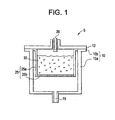
- FIG. 1 is a schematic view of a conventional zinc feedwater system 5.
- the zinc feedwater system 5 may generally includes a pressure vessel 10 with piping 15 leading into the pressure vessel 10 and piping 20 leading out of the pressure vessel 10.
- the pressure vessel may include a body 10a with a flange 10b and a cover 12.
- the zinc feedwater system 5 also includes a zinc feedwater basket 25 within the pressure vessel 10 for holding a bed of zinc pellets 30.
- a conventional zinc feedwater basket 25 includes a vertical wall 25a and a perforated plate bottom 25b.
- the zinc feedwater system 5 also includes a flow control valve (not shown) attached to the piping 20 leaving the pressure vessel through the cover 12.
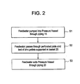
- FIG. 2 is a flowchart illustrating a method of the flowing feedwater through the zinc feedwater system.
- Feedwater is pumped into the pressure vessel 10 through the piping 15 in step S1.
- the feedwater passes upward through the perforated bottom plate 25b and the bed of zinc pellets 30 supported in the basket 25 in step 2.
- Feedwater passes from the bed of zinc pellets 30 and into the outlet piping 20 in step 3.
- Feedwater may leave the zinc feedwater system via the outlet piping 20.
- Example embodiments provide a replacement basket (a downward flow basket) which may house a bed of pellets and allow for a fluid to pass through the bed of pellets in a downward direction. Because the direction of fluid flow in the replacement basket is downward, the downward flow may prevent the bed from fluidizing, minimizing the chipping of zinc pellets.
- Example embodiments also provide for a method of providing pellets into the basket.
- Example embodiments also provide for a system using the basket.
- a downward flow basket may include at least one vertical wall with an upper surface portion and a lower surface portion, at least one vertical wall including at least one hole near the upper surface portion.
- the downward flow basket in accordance with example embodiments, may also include a solid bottom attached to the lower surface portion of the at least one vertical wall, the bottom and at least one vertical wall enclosing an inner space of the basket.
- a downward flow basket may also include a perforated plate above the bottom of the downward flow basket and within the inner space of the basket, the perforated plate and the bottom may define a plenum into which fluid exiting the pellets may flow.
- a downward flow basket may also include a central pipe extending from the plenum up through the downward flow basket.
- a system may include a pressure vessel and the above described downward flow basket, wherein the downward flow basket is located inside the pressure vessel.
- the pressure vessel may include a top flange that may be a stepped flange.
- the top of the downward flow basket may be configured to contact the stepped portion of the stepped flange.
- a method of loading pellets into the above described downward flow basket may include blocking the central pipe of the basket and pouring pellets around the blocked central pipe and into the basket to fill the inner space of the basket.
- the central pipe may be blocked with a tool and the tool may include a funnel configured to guide the pellets into the basket.
- first, second, etc. may be used herein to describe various elements, components, regions, layers, and/or sections, these elements, components, regions, layers, and/or sections should not be limited by these terms. These terms are only used to distinguish one element, component, region, layer, and/or section from another element, component, region, layer, and/or section. Thus, a first element, component, region, layer, or section discussed below could be termed a second element, component, region, layer, or section without departing from the teachings of example embodiments.
- spatially relative terms such as “beneath”, “below”, “lower”, “above”, “upper”, and the like, may be used herein for ease of description to describe one element or feature's relationship to another element(s) or feature(s) as illustrated in the figures. It will be understood that the spatially relative terms are intended to encompass different orientations of the device in use or operation in addition to the orientation depicted in the figures. For example, if the device in the figures is turned over, elements described as “below” or “beneath” other elements or features would then be oriented “above” the other elements or features. Thus, the exemplary term “below” can encompass both an orientation of above and below. The device may be otherwise oriented (rotated 90 degrees or at other orientations) and the spatially relative descriptors used herein interpreted accordingly.
- Embodiments described herein will refer to plan views and/or cross-sectional views by way of ideal schematic views. Accordingly, the views may be modified depending on manufacturing technologies and/or tolerances. Therefore, example embodiments are not limited to those shown in the views, but include modifications in configuration formed on the basis of manufacturing processes. Therefore, regions exemplified in figures have schematic properties and shapes of regions shown in figures exemplify specific shapes or regions of elements, and do not limit example embodiments.
- Example embodiments will now be described more fully hereinafter with reference to FIGS. 3A-3D , 4A-4D , 6 and 7 , in which example embodiments are shown.
- Example embodiments may, however, be embodied in different forms and should not be construed as limited to the embodiments set forth herein. Rather, example embodiments are provided so that this disclosure will be thorough and complete, and will fully convey the scope of example embodiments to those skilled in the art.
- Like numbers refer to like elements throughout the specification.
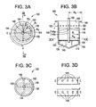
- the downward flow basket may include a bottom 110, and at least one vertical wall 115 connected to the bottom 110.
- the vertical wall 115 as shown in FIGS. 3A-3C , may be a vertically oriented and cylindrically shaped wall with an inside radius Ri and an outside radius Ro.
- the vertical wall, 115 may include an upper surface portion 105 and a lower surface portion 160.
- the upper surface portion 105 of the vertical wall 115 may include a flange 106.
- the flange 106 may be a relatively short vertically oriented and cylindrically shaped flange with an inside radius equal to the outside radius Ro of the vertical wall 115 and an outside radius Ro' larger than the outside radius Roof the vertical wall 115.
- the centerline of the top flange 106 and the centerline of the vertical wall 115 may be coincident. Furthermore, as shown in FIG. 3B , the top of the flange 106 may be coincident with the top of the vertical wall 115.
- the bottom of the downward flow basket 110 may be shaped in a variety of configurations to redirect fluid flow towards the vertical wall 115.
- the bottom of the downward flow basket 110 may, for example, be cone shaped.
- the base of the cone shaped bottom 110 may connect to the lower surface portion 160 of the vertical wall 115 which may be coincident with the bottom of the vertical wall 115.
- the vertex of the cone shaped bottom 110 may be directed downwards and away from vertical wall 115 and the vertex may be coincident with the centerline of the vertical wall 115.
- the outer radius of the base of the cone shaped bottom 110 in accordance with example embodiments, may be equal to the outer radius Ro of the vertical wall 115.
- the thickness of the bottom 110 may be equal to the thickness of the vertical wall 115. However, example embodiments are not limited thereto. For example, the thickness of the bottom 110 may be thicker than the thickness of the wall 115 or the thickness of the bottom 110 may be thinner than the thickness of the wall 115. Furthermore, although FIG. 3B illustrates a cone-shaped bottom, example embodiments are not limited thereto. For example, the bottom could be a hemisphere, or a geometric shape with an elliptical or parabolic profile, or it could be flat.
- the vertical wall 115 may include holes 120 near the top of the vertical wall 115.
- the holes 120 may be circular holes or rectangular holes, as illustrated in FIG. 3D , and may be positioned symmetrically around the perimeter of vertical wall 115. However, the holes 120 are not limited to these shapes.
- the holes are configured to allow feedwater to pass from the outside of the vertical wall 115 to the inside of the downward flow basket 100.
- a mesh (not shown) may be provided over the hole in order to prevent contaminates from entering the downward flow basket 100.
- the mesh may be provided either on the inside of the vertical wall 115 and/or the outside of the vertical wall 115. In the alternative, the holes may be constructed such that the mesh is integral with the wall. Examples of meshed holes and open holes are illustrated in FIGS. 4A-4D .
- zinc pellets 125 may be stored inside the downward flow basket 100.
- the zinc pellets may be vertically supported by a perforated plate 130 and horizontally restrained by the vertical wall 115.
- the perforated plate may be positioned in the inside of the downward flow basket 100 above the bottom 110.
- the perforated plate 130 may be formed as an annular plate such that the thickness of the plate is aligned in the vertical direction and the center of the plate is aligned with the center of the vertical wall 115.
- the outer radius of the annular perforated plate 130 may be equal to or less than the inside radius Ri of the vertical wall 115.
- the inner radius of the annular perforated plate may be equal to or larger than the outer diameter of a discharge pipe 145 (to be discussed later).
- the space between the perforated plate 130 and the bottom 110 constitutes a plenum 140 between the perforated plate 130 and the bottom 110.
- the perforated plate 130 may be attached to and/or supported by the vertical wall 115 and/or may be supported by vertically oriented support braces 135.
- the support braces 135 may be attached to the vertical wall and/or the bottom 110 of the downward flow basket and may be arranged symmetrically around the center of the downward flow basket as shown in FIG. 3C .
- FIG. 3C shows four symmetrically placed braces 135, example embodiments are not limited thereto.
- the bottom of the support braces may be supported by the bottom 110 of the downward flow basket 100 and formed to match the contour of the bottom 110.
- the bottom 110 of the downward flow basket 100 is cone-shaped then the bottom of the support braces 135 may be angled to match the angle of the cone.
- example embodiments are not limited thereto.
- the bottom of the support braces 135 could be curve shaped in the event the bottom 110 of the downward flow basket 100 had a curved profile.
- the support braces 135 illustrated in FIG. 3B appear solid, the support braces may include holes in order to allow fluid to pass through the support brace 135 instead of flowing around the support brace 135.
- the downward flow basket also may include a central pipe 145 extending from the plenum 140 up through the downward flow basket as shown in FIG. 3B .
- the outer radius of the central pipe 145 may be equal to or smaller than the inner radius of the annular perforated plate 130 as shown in FIG. 3C .
- the central pipe 145 may be a single pipe.
- the central pipe may be comprised of an upper flow tube 145a and a lower flow tube 145b and may be held together as a pipe-in-pipe arrangement.
- the central pipe 145 may be supported by support braces 150.
- the support braces 150 may be attached to the inside surface of the vertical wall 115 and may be attached to the central pipe 145.
- the support braces 150 may be symmetrically positioned around the pipe as shown in FIGS. 3A and 3B . If the central pipe includes a lower flow tube 145b and an upper flow tube 145a, the lower flow tube may be supported by the support braces 150.
- a filter 155 may be located in the central pipe near the top of the downward flow basket 100. An additional filter (not shown) may also be placed near the bottom of the central pipe 145.
- FIG. 5 describes the flow of feedwater in a zinc feedwater system using a conventional flow basket.
- feedwater is fed into a pressure vessel 10 through a pipe 15.
- the flow of feedwater F1 into the pressure vessel 10 may spread and transform into pattern FC2 after entering the pressure vessel 10 but before passing through the perforated plate 25b.
- the flow of feedwater may pass through the perforated plate 25b and the bed of zinc pellets 30 and may leave the pressure vessel through the pipe 20.
- the flow of feedwater is sufficiently low, the zinc pellets may remain in place and water may flow around the pellets.
- the forces exerted on the pellets by the feedwater may cause the pellets to displace and move with respect to each other. This movement, as explained above, can damage the zinc pellets causing particles to enter the reactor thereby adversely affecting the feedwater Zn control.
- FIG. 6 describes the flow of feedwater through a zinc feedwater system using the downward flow basket in accordance with example embodiments.
- feedwater may be fed into a pressure vessel at one end, however, in example embodiments, this flow is redirected by the bottom of the downward flow basket 110 to the outside of the vertical walls of the downward flow basket 115 (see FIG. 6 , F for direction of feedwater into the pressure vessel, see FIG. 6 , FE2 for the flow of water being redirected to the vertical wall 115 by the bottom of the downward flow basket 110).
- the feedwater may flow along the outside of the vertical wall of the downward flow basket 115 towards the top of the downward flow basket (see FIG. 6 , FE3).
- feedwater passes through the holes 120 in the vertical wall 115 and into the downward flow basket 100 (see FIG. 6 , FE4).
- the feedwater may flow into the plenum 140, accordingly, the feedwater in the downward flow basket may flow in a downward direction, through the bed of zinc pellets 125, through a perforated plate 130, and into the plenum 140 (see FIG. 6 , FE5).
- the feedwater may exit the downward flow basket by flowing up inside the central pipe 145 (see FIG. 6 , FE6 and FE7).
- the flow of feedwater presses the zinc pellets 125 against the perforated plate 130 and the vertical wall 115. Accordingly, the force of water against the zinc pellets 125 compresses the pellets 125 reducing or preventing their fluidization.
- zinc pellets may be placed into the flow basket by removing the cover of the pressure vessel 12 and pouring the zinc pellets 30 directly into the flow basket 25.
- a central pipe 145 within the downward flow basket may be exposed when the pressure vessel cover 12 is removed, care must be taken to ensure the pellets do not enter the central pipe 145 during filling.
- a method for loading pellets into the downward flow basket may include providing a blocker 200 to block a central pipe 145.
- a method for loading pellets into the downward flow basket may also include pouring the pellets into the downward flow basket around the blocked central pipe 145.
- a special tool may be used to block the central pipe. This tool may be configured to include a funnel 205 for guiding the pellets into the basket as shown in FIG. 7 .
- the downward flow basket may be configured to replace the conventional flow basket in conventional zinc feedwater systems.
- the pressure vessel used in conjunction with the conventional flow basket, has a stepped flange in which the conventional flow basket mates.
- the downward flow basket 100 could likewise be configured so that the upper surface portion of the downward flow basket 105 mates with the stepped flange of a conventional pressure vessel in the same manner as the conventional flow basket.
- the downward flow basket may be used for retrofitting existing systems.
- the downward flow basket may be made of materials identical to those of the conventional flow basket, for example, stainless steel. However, the downward flow basket could be made of any number of materials such as glass, plastic, ceramic, metal, or composite material.
Landscapes
- Physics & Mathematics (AREA)
- Engineering & Computer Science (AREA)
- Plasma & Fusion (AREA)
- General Engineering & Computer Science (AREA)
- High Energy & Nuclear Physics (AREA)
- Manufacture And Refinement Of Metals (AREA)
- Processing And Handling Of Plastics And Other Materials For Molding In General (AREA)
Abstract
Description
- Example embodiments relate to an apparatus for holding a bed of zinc pellets, and more particularly, a replacement basket for holding a bed of zinc pellets through which reactor feedwater may pass. Example embodiments also relate to a system including the apparatus and a method of filling the apparatus with zinc pellets.
- In conventional boiling water reactors, zinc may be added to the reactor feedwater to reduce the levels of radioactivity in the reactor piping. In many conventional boiling water reactors, zinc is introduced into the feedwater by a zinc feedwater system.
FIG. 1 is a schematic view of a conventionalzinc feedwater system 5. Thezinc feedwater system 5 may generally includes apressure vessel 10 withpiping 15 leading into thepressure vessel 10 and piping 20 leading out of thepressure vessel 10. The pressure vessel may include abody 10a with aflange 10b and acover 12. Thezinc feedwater system 5 also includes azinc feedwater basket 25 within thepressure vessel 10 for holding a bed ofzinc pellets 30. A conventionalzinc feedwater basket 25 includes avertical wall 25a and aperforated plate bottom 25b. Thezinc feedwater system 5 also includes a flow control valve (not shown) attached to thepiping 20 leaving the pressure vessel through thecover 12. -
FIG. 2 is a flowchart illustrating a method of the flowing feedwater through the zinc feedwater system. Feedwater is pumped into thepressure vessel 10 through thepiping 15 in step S1. The feedwater passes upward through theperforated bottom plate 25b and the bed ofzinc pellets 30 supported in thebasket 25 instep 2. Feedwater passes from the bed ofzinc pellets 30 and into theoutlet piping 20 instep 3. Feedwater may leave the zinc feedwater system via theoutlet piping 20. - It has been observed that when the rate of flow of feedwater passing through the bed of
zinc pellets 30 is relatively high, the pellets tend to move in a fluidized manner. This fluidization increases the possibility of pellet chipping and subsequent introduction of zinc particles into the reactor. From an operational standpoint, large intrusions of zinc into the feedwater, due to these particles, may cause unexpected spikes in feedwater zinc concentrations which are undesirable for fuel. - Example embodiments provide a replacement basket (a downward flow basket) which may house a bed of pellets and allow for a fluid to pass through the bed of pellets in a downward direction. Because the direction of fluid flow in the replacement basket is downward, the downward flow may prevent the bed from fluidizing, minimizing the chipping of zinc pellets. Example embodiments also provide for a method of providing pellets into the basket. Example embodiments also provide for a system using the basket.
- According to example embodiments, a downward flow basket may include at least one vertical wall with an upper surface portion and a lower surface portion, at least one vertical wall including at least one hole near the upper surface portion. The downward flow basket, in accordance with example embodiments, may also include a solid bottom attached to the lower surface portion of the at least one vertical wall, the bottom and at least one vertical wall enclosing an inner space of the basket. According to example embodiments, a downward flow basket may also include a perforated plate above the bottom of the downward flow basket and within the inner space of the basket, the perforated plate and the bottom may define a plenum into which fluid exiting the pellets may flow. According to example embodiments, a downward flow basket may also include a central pipe extending from the plenum up through the downward flow basket.
- According to example embodiments, a system may include a pressure vessel and the above described downward flow basket, wherein the downward flow basket is located inside the pressure vessel. According to example embodiments, the pressure vessel may include a top flange that may be a stepped flange. According to example embodiments, the top of the downward flow basket may be configured to contact the stepped portion of the stepped flange.
- According to example embodiments, a method of loading pellets into the above described downward flow basket may include blocking the central pipe of the basket and pouring pellets around the blocked central pipe and into the basket to fill the inner space of the basket. According to example embodiments, the central pipe may be blocked with a tool and the tool may include a funnel configured to guide the pellets into the basket.
- There follows a detailed description of embodiments of the invention by way of example only with reference to the accompanying drawings, in which:
-
FIG. 1 is a schematic view of a conventional zinc feedwater system including a conventional flow basket for holding zinc pellets; -
FIG. 2 is a flowchart illustrating a method of flowing feedwater through a conventional zinc feedwater system; -
FIG. 3A is a top schematic view of a downward flow basket according to example embodiments; -
FIG. 3B is a section view of the downward flow basket illustrated inFIG. 3A ; -
FIG. 3C is a section view of the downward flow basket illustrated inFIG. 3B ; -
FIG. 3D is an elevation view of the vertical wall from c-c' as shown inFIG. 3A and from z-z' as shown inFIG. 3B . -
FIG. 4A is a view of a meshed hole in a vertical wall in the downward flow basket according to example embodiments; -
FIG. 4B is a view of a meshed hole in a vertical wall in the downward flow basket according to example embodiments; -
FIG. 4C is a view of a meshed hole in a vertical wall in the downward flow basket according to example embodiments; -
FIG 4D is a view of an open hole in a vertical wall in the downward flow basket according to example embodiments; -
FIG. 5 is a view illustrating a flow pattern of feedwater through a conventional zinc feedwater system using a conventional flow basket; -
FIG. 6 is a view illustrating a flow pattern of feedwater through a conventional zinc feedwater system using a downward flow basket according to example embodiments; -
FIG. 7 is a view illustrating a method for pellet reloading in a downward flow basket according to example embodiments. - Example embodiments will now be described more fully with reference to the accompanying drawings, in which example embodiments are shown. The invention may, however, be embodied in different forms and should not be construed as limited to the embodiments set forth herein. Rather, these embodiments are provided so that this disclosure will be thorough and complete, and will fully convey the scope of the invention to those skilled in the art. In the drawings, the sizes of components may be exaggerated for clarity.
- It will be understood that when an element or layer is referred to as being "on", "connected to", or "coupled to" another element or layer, it can be directly on, connected to, or coupled to the other element or layer or intervening elements or layers that may be present. In contrast, when an element is referred to as being "directly on", "directly connected to", or "directly coupled to" another element or layer, there are no intervening elements or layers present. As used herein, the term "and/or" includes any and all combinations of one or more of the associated listed items.
- It will be understood that, although the terms first, second, etc. may be used herein to describe various elements, components, regions, layers, and/or sections, these elements, components, regions, layers, and/or sections should not be limited by these terms. These terms are only used to distinguish one element, component, region, layer, and/or section from another element, component, region, layer, and/or section. Thus, a first element, component, region, layer, or section discussed below could be termed a second element, component, region, layer, or section without departing from the teachings of example embodiments.
- Spatially relative terms, such as "beneath", "below", "lower", "above", "upper", and the like, may be used herein for ease of description to describe one element or feature's relationship to another element(s) or feature(s) as illustrated in the figures. It will be understood that the spatially relative terms are intended to encompass different orientations of the device in use or operation in addition to the orientation depicted in the figures. For example, if the device in the figures is turned over, elements described as "below" or "beneath" other elements or features would then be oriented "above" the other elements or features. Thus, the exemplary term "below" can encompass both an orientation of above and below. The device may be otherwise oriented (rotated 90 degrees or at other orientations) and the spatially relative descriptors used herein interpreted accordingly.
- Embodiments described herein will refer to plan views and/or cross-sectional views by way of ideal schematic views. Accordingly, the views may be modified depending on manufacturing technologies and/or tolerances. Therefore, example embodiments are not limited to those shown in the views, but include modifications in configuration formed on the basis of manufacturing processes. Therefore, regions exemplified in figures have schematic properties and shapes of regions shown in figures exemplify specific shapes or regions of elements, and do not limit example embodiments.
- Example embodiments will now be described more fully hereinafter with reference to
FIGS. 3A-3D ,4A-4D ,6 and 7 , in which example embodiments are shown. Example embodiments may, however, be embodied in different forms and should not be construed as limited to the embodiments set forth herein. Rather, example embodiments are provided so that this disclosure will be thorough and complete, and will fully convey the scope of example embodiments to those skilled in the art. Like numbers refer to like elements throughout the specification. - The downward flow basket, according to example embodiments, may include a bottom 110, and at least one
vertical wall 115 connected to the bottom 110. Thevertical wall 115, as shown inFIGS. 3A-3C , may be a vertically oriented and cylindrically shaped wall with an inside radius Ri and an outside radius Ro. The vertical wall, 115 may include anupper surface portion 105 and alower surface portion 160. Theupper surface portion 105 of thevertical wall 115 may include aflange 106. As shown inFIGS. 3A - 3B , theflange 106 may be a relatively short vertically oriented and cylindrically shaped flange with an inside radius equal to the outside radius Ro of thevertical wall 115 and an outside radius Ro' larger than the outside radius Roof thevertical wall 115. As shown inFIG. 3A , the centerline of thetop flange 106 and the centerline of thevertical wall 115 may be coincident. Furthermore, as shown inFIG. 3B , the top of theflange 106 may be coincident with the top of thevertical wall 115. - The bottom of the
downward flow basket 110 may be shaped in a variety of configurations to redirect fluid flow towards thevertical wall 115. Referring toFIG. 3B , the bottom of thedownward flow basket 110 may, for example, be cone shaped. The base of the cone shapedbottom 110 may connect to thelower surface portion 160 of thevertical wall 115 which may be coincident with the bottom of thevertical wall 115. The vertex of the cone shapedbottom 110 may be directed downwards and away fromvertical wall 115 and the vertex may be coincident with the centerline of thevertical wall 115. The outer radius of the base of the cone shapedbottom 110, in accordance with example embodiments, may be equal to the outer radius Ro of thevertical wall 115. The thickness of the bottom 110 may be equal to the thickness of thevertical wall 115. However, example embodiments are not limited thereto. For example, the thickness of the bottom 110 may be thicker than the thickness of thewall 115 or the thickness of the bottom 110 may be thinner than the thickness of thewall 115. Furthermore, althoughFIG. 3B illustrates a cone-shaped bottom, example embodiments are not limited thereto. For example, the bottom could be a hemisphere, or a geometric shape with an elliptical or parabolic profile, or it could be flat. - The
vertical wall 115 may includeholes 120 near the top of thevertical wall 115. Theholes 120, for example, may be circular holes or rectangular holes, as illustrated inFIG. 3D , and may be positioned symmetrically around the perimeter ofvertical wall 115. However, theholes 120 are not limited to these shapes. The holes are configured to allow feedwater to pass from the outside of thevertical wall 115 to the inside of thedownward flow basket 100. A mesh (not shown) may be provided over the hole in order to prevent contaminates from entering thedownward flow basket 100. The mesh may be provided either on the inside of thevertical wall 115 and/or the outside of thevertical wall 115. In the alternative, the holes may be constructed such that the mesh is integral with the wall. Examples of meshed holes and open holes are illustrated inFIGS. 4A-4D . - Inside the
downward flow basket 100, according to example embodiments,zinc pellets 125 may be stored. The zinc pellets may be vertically supported by aperforated plate 130 and horizontally restrained by thevertical wall 115. The perforated plate may be positioned in the inside of thedownward flow basket 100 above the bottom 110. Theperforated plate 130 may be formed as an annular plate such that the thickness of the plate is aligned in the vertical direction and the center of the plate is aligned with the center of thevertical wall 115. The outer radius of the annularperforated plate 130 may be equal to or less than the inside radius Ri of thevertical wall 115. The inner radius of the annular perforated plate may be equal to or larger than the outer diameter of a discharge pipe 145 (to be discussed later). The space between theperforated plate 130 and the bottom 110 constitutes aplenum 140 between theperforated plate 130 and the bottom 110. - The
perforated plate 130 may be attached to and/or supported by thevertical wall 115 and/or may be supported by vertically oriented support braces 135. The support braces 135 may be attached to the vertical wall and/or thebottom 110 of the downward flow basket and may be arranged symmetrically around the center of the downward flow basket as shown inFIG. 3C . AlthoughFIG. 3C shows four symmetrically placedbraces 135, example embodiments are not limited thereto. - The bottom of the support braces may be supported by the
bottom 110 of thedownward flow basket 100 and formed to match the contour of the bottom 110. For example, if the bottom 110 of thedownward flow basket 100 is cone-shaped then the bottom of the support braces 135 may be angled to match the angle of the cone. However, example embodiments are not limited thereto. For example, the bottom of the support braces 135 could be curve shaped in the event thebottom 110 of thedownward flow basket 100 had a curved profile. Although the support braces 135 illustrated inFIG. 3B appear solid, the support braces may include holes in order to allow fluid to pass through thesupport brace 135 instead of flowing around thesupport brace 135. - The downward flow basket, according to example embodiments, also may include a
central pipe 145 extending from theplenum 140 up through the downward flow basket as shown inFIG. 3B . The outer radius of thecentral pipe 145 may be equal to or smaller than the inner radius of the annularperforated plate 130 as shown inFIG. 3C . Thecentral pipe 145 may be a single pipe. In the alternative, the central pipe may be comprised of anupper flow tube 145a and alower flow tube 145b and may be held together as a pipe-in-pipe arrangement. - The
central pipe 145 may be supported by support braces 150. The support braces 150 may be attached to the inside surface of thevertical wall 115 and may be attached to thecentral pipe 145. The support braces 150 may be symmetrically positioned around the pipe as shown inFIGS. 3A and 3B . If the central pipe includes alower flow tube 145b and anupper flow tube 145a, the lower flow tube may be supported by the support braces 150. Afilter 155 may be located in the central pipe near the top of thedownward flow basket 100. An additional filter (not shown) may also be placed near the bottom of thecentral pipe 145. -
FIG. 5 describes the flow of feedwater in a zinc feedwater system using a conventional flow basket. As illustrated inFIG. 5 , feedwater is fed into apressure vessel 10 through apipe 15. The flow of feedwater F1 into thepressure vessel 10 may spread and transform into pattern FC2 after entering thepressure vessel 10 but before passing through theperforated plate 25b. The flow of feedwater may pass through theperforated plate 25b and the bed ofzinc pellets 30 and may leave the pressure vessel through thepipe 20. If the flow of feedwater is sufficiently low, the zinc pellets may remain in place and water may flow around the pellets. However, if the flow is sufficiently high, the forces exerted on the pellets by the feedwater may cause the pellets to displace and move with respect to each other. This movement, as explained above, can damage the zinc pellets causing particles to enter the reactor thereby adversely affecting the feedwater Zn control. -
FIG. 6 describes the flow of feedwater through a zinc feedwater system using the downward flow basket in accordance with example embodiments. As above, feedwater may be fed into a pressure vessel at one end, however, in example embodiments, this flow is redirected by the bottom of thedownward flow basket 110 to the outside of the vertical walls of the downward flow basket 115 (seeFIG. 6 , F for direction of feedwater into the pressure vessel, seeFIG. 6 , FE2 for the flow of water being redirected to thevertical wall 115 by the bottom of the downward flow basket 110). The feedwater may flow along the outside of the vertical wall of thedownward flow basket 115 towards the top of the downward flow basket (seeFIG. 6 , FE3). Near the top of the downward flow basket, feedwater passes through theholes 120 in thevertical wall 115 and into the downward flow basket 100 (seeFIG. 6 , FE4). At the bottom of thedownward flow basket 110 the feedwater may flow into theplenum 140, accordingly, the feedwater in the downward flow basket may flow in a downward direction, through the bed ofzinc pellets 125, through aperforated plate 130, and into the plenum 140 (seeFIG. 6 , FE5). Once in the plenum, the feedwater may exit the downward flow basket by flowing up inside the central pipe 145 (seeFIG. 6 , FE6 and FE7). - According to example embodiments, because the direction of feedwater within the
downward flow basket 100 is directed downwards, the flow of feedwater presses thezinc pellets 125 against theperforated plate 130 and thevertical wall 115. Accordingly, the force of water against thezinc pellets 125 compresses thepellets 125 reducing or preventing their fluidization. - In conventional flow baskets, zinc pellets may be placed into the flow basket by removing the cover of the
pressure vessel 12 and pouring thezinc pellets 30 directly into theflow basket 25. However, according to example embodiments, because acentral pipe 145 within the downward flow basket may be exposed when thepressure vessel cover 12 is removed, care must be taken to ensure the pellets do not enter thecentral pipe 145 during filling. - Referring to
FIG. 7 , a method for loading pellets into the downward flow basket according to example embodiments may include providing ablocker 200 to block acentral pipe 145. According to example embodiments, a method for loading pellets into the downward flow basket may also include pouring the pellets into the downward flow basket around the blockedcentral pipe 145. According to example embodiments, a special tool may be used to block the central pipe. This tool may be configured to include afunnel 205 for guiding the pellets into the basket as shown inFIG. 7 . - Although the configuration of the downward flow basket, according to example embodiments, is at least internally different from that of the conventional flow basket, the size of the downward flow basket may be similar to that of the conventional flow basket. Therefore, the downward flow basket, according to example embodiments, may be configured to replace the conventional flow basket in conventional zinc feedwater systems. For example, the pressure vessel, used in conjunction with the conventional flow basket, has a stepped flange in which the conventional flow basket mates. The
downward flow basket 100, according to example embodiments, could likewise be configured so that the upper surface portion of thedownward flow basket 105 mates with the stepped flange of a conventional pressure vessel in the same manner as the conventional flow basket. Thus, the downward flow basket may be used for retrofitting existing systems. - The downward flow basket may be made of materials identical to those of the conventional flow basket, for example, stainless steel. However, the downward flow basket could be made of any number of materials such as glass, plastic, ceramic, metal, or composite material.
- While example embodiments have been particularly shown and described with reference to example embodiments thereof, it will be understood by those of ordinary skill in the an that various changes in form and details may be made therein without departing from the scope of the following claims.
Claims (15)
- A basket (100) comprising:at least one vertical wall (115) with an upper surface portion (105) and a lower surface portion (160), the at least one vertical wall (115) including at least one hole (120) near the upper surface portion (105);a bottom (110) attached to the lower surface portion (160) of the at least one vertical wall (115), the bottom (110) and the at least one vertical wall (115) enclosing an inner space of the basket (100);a perforated plate (130) above the bottom (110) and within the inner space of the basket (100), the perforated plate (130) and the bottom (110) defining a plenum (140) into which fluid flowing out of a pellet bed (125) may flow; anda central pipe (145) extending from the plenum (140) up through the basket (100).
- The basket (100) of claim 1, wherein the upper surface portion (105) of the at least one vertical wall (115) includes a flange (106).
- The basket (100) of claim 1 or 2, wherein the bottom (110) has a flat, conical or elliptical profile.
- The basket (100) of any of the preceding claims, wherein the central pipe (145) includes a filter (155) at a top of the central pipe (145).
- The basket (100) of any of the preceding claims, wherein the central pipe (145) includes a filter at a bottom of the central pipe (145).
- The basket (100) of any of the preceding claims, further comprising:at least one support brace (150) configured to support the central pipe (145), wherein the at least one support brace (150) is attached to an inside surface of the at least one vertical wall (115).
- The basket (100) of any of the preceding claims, wherein the central pipe (145) includes an upper flow tube (145a) and a lower flow tube (145b).
- The basket (100) of claim 7, further comprising:at least one support brace (150) configured to support the lower flow tube (145b), wherein the at least one support brace (150) is attached to an inside surface of the at least one vertical wall (115).
- The basket of any of the preceding claims, further comprising:at least one support brace configured to support the perforated plate, the at least one support brace contacting an upper surface of the bottom.
- The basket of any of the preceding claims, wherein the perforated plate is configured to support a bed of pellets.
- A system comprising:a pressure vessel (10); anda basket (100) disposed inside the pressure vessel (10), the basket (100) including,at least one vertical wall (115) with an upper surface portion (105) and a lower surface portion (160), the at least one vertical wall (115) including at least one hole (120) near the upper surface portion (105);a bottom (110) attached to the lower surface portion (160) of the at least one vertical wall (115), the bottom (110) and the at least one vertical wall (115) enclosing an inner space of the basket (100);a perforated plate (130) above the bottom (110) and within the inner space of the basket (100), the perforated plate (130) and the bottom (110) defining a plenum (140) into which fluid flowing from a pellet bed (125) may flow; anda central pipe (145) extending from the plenum (140) up through the basket (100).
- The system of claim 11, wherein the pressure vessel includes a stepped flange and the upper surface portion of the at least one vertical wall is configured to contact a stepped portion of the stepped flange.
- A method of loading pellets (125) into the basket (100) of claim 1, comprising:blocking the central pipe (145) of the basket (100); andpouring pellets (125) around the central pipe (145) and into the basket (100) to fill the inner space.
- The method of claim 13, wherein the central pipe is blocked with a tool, the tool including a funnel configured to guide the pellets into the basket.
- The method of claim 13 or 14, wherein a cover of a pressure vessel is removed to expose the basket prior to blocking the central pipe of the basket.
Applications Claiming Priority (1)
| Application Number | Priority Date | Filing Date | Title |
|---|---|---|---|
| US12/232,853 US20100074389A1 (en) | 2008-09-25 | 2008-09-25 | Replacement basket, a system using the replacement basket, and a method for loading the replacement basket |
Publications (2)
| Publication Number | Publication Date |
|---|---|
| EP2169686A1 EP2169686A1 (en) | 2010-03-31 |
| EP2169686B1 true EP2169686B1 (en) | 2011-12-07 |
Family
ID=41466677
Family Applications (1)
| Application Number | Title | Priority Date | Filing Date |
|---|---|---|---|
| EP09170402A Active EP2169686B1 (en) | 2008-09-25 | 2009-09-16 | Replacement basket, a system using the replacement basket, and a method for loading the replacement basket |
Country Status (6)
| Country | Link |
|---|---|
| US (2) | US20100074389A1 (en) |
| EP (1) | EP2169686B1 (en) |
| JP (1) | JP5662663B2 (en) |
| AT (1) | ATE536620T1 (en) |
| ES (1) | ES2375821T3 (en) |
| MX (1) | MX2009010333A (en) |
Family Cites Families (15)
| Publication number | Priority date | Publication date | Assignee | Title |
|---|---|---|---|---|
| US2802724A (en) * | 1956-04-05 | 1957-08-13 | Tom R Johnson | Combined dry chemical dissolver and feeder |
| JPS58151438U (en) * | 1982-03-30 | 1983-10-11 | 三菱電機株式会社 | reaction tube |
| JPS59228195A (en) * | 1983-06-10 | 1984-12-21 | 日揮株式会社 | Device for treating radioactive waste water |
| IN165082B (en) * | 1985-05-15 | 1989-08-12 | Ammonia Casale Sa | |
| US4753779A (en) * | 1985-08-02 | 1988-06-28 | The Boeing Company | Sliding tray reactor |
| US5403387A (en) * | 1991-09-06 | 1995-04-04 | Reading Technologies, Inc. | Apparatus for removing moisture from a gas |
| JP3118783B2 (en) * | 1995-06-28 | 2000-12-18 | 株式会社三好商会 | Batch type wastewater treatment method and its treatment device |
| US6306354B1 (en) * | 1996-05-17 | 2001-10-23 | International Fuel Cells, Llc | Shift converter |
| US5769909A (en) * | 1996-05-31 | 1998-06-23 | International Fuel Cells Corp. | Method and apparatus for desulfurizing fuel gas |
| CN1073869C (en) * | 1997-03-26 | 2001-10-31 | 株式会社日立制作所 | Fluidized bed filtering apparatus |
| IL126775A (en) * | 1998-10-27 | 2002-03-10 | Tsabari Yigal | Water treatment system |
| US6190623B1 (en) * | 1999-06-18 | 2001-02-20 | Uop Llc | Apparatus for providing a pure hydrogen stream for use with fuel cells |
| US20020074292A1 (en) * | 2000-09-26 | 2002-06-20 | Andreas Schlegel | Adsorption vessels |
| IL147279A0 (en) * | 2001-12-24 | 2002-08-14 | Schneider Igor | Compact water treatment device |
| JP2007033352A (en) * | 2005-07-29 | 2007-02-08 | Hitachi Ltd | Zinc supply method to nuclear reactor |
-
2008
- 2008-09-25 US US12/232,853 patent/US20100074389A1/en not_active Abandoned
-
2009
- 2009-09-16 ES ES09170402T patent/ES2375821T3/en active Active
- 2009-09-16 AT AT09170402T patent/ATE536620T1/en active
- 2009-09-16 EP EP09170402A patent/EP2169686B1/en active Active
- 2009-09-17 JP JP2009215221A patent/JP5662663B2/en active Active
- 2009-09-25 MX MX2009010333A patent/MX2009010333A/en active IP Right Grant
-
2011
- 2011-12-30 US US13/340,749 patent/US20120103908A1/en not_active Abandoned
Also Published As
| Publication number | Publication date |
|---|---|
| US20120103908A1 (en) | 2012-05-03 |
| US20100074389A1 (en) | 2010-03-25 |
| JP5662663B2 (en) | 2015-02-04 |
| EP2169686A1 (en) | 2010-03-31 |
| MX2009010333A (en) | 2010-05-03 |
| JP2010078601A (en) | 2010-04-08 |
| ES2375821T3 (en) | 2012-03-06 |
| ATE536620T1 (en) | 2011-12-15 |
Similar Documents
| Publication | Publication Date | Title |
|---|---|---|
| CN105830167B (en) | Filtration and discharge systems used in nuclear power plants | |
| WO2001023080A1 (en) | Catalytic reactor | |
| KR101649398B1 (en) | Ion exchange equipment | |
| EP2169686A1 (en) | Replacement basket, a system using the replacement basket, and a method for loading the replacement basket | |
| JPH0446613B2 (en) | ||
| CN216987587U (en) | Device for loading and unloading materials of catalyst of fixed bed reactor | |
| US20190282985A1 (en) | Systems and methods for improving flow in radial flow reactor | |
| CN111116548B (en) | A kind of inferior sulfolane regeneration equipment, system and method | |
| KR101555692B1 (en) | Imbedded cfvs for nuclear power plant | |
| JP4278612B2 (en) | Method and apparatus for packing chromatography column | |
| CN106232223B (en) | Moving bed catalytic reactor for managing catalyst circulation interruption and process using the same | |
| EP2937867B1 (en) | Containment filtered venting system used for nuclear power plant | |
| US8071047B2 (en) | Centerpipe design for radial flow reactor | |
| US6689329B2 (en) | Fouling tolerant fixed bed reactor with virtual second bed | |
| US7901640B2 (en) | Optimized counter-current flow baffle | |
| CN107949434B (en) | Product Containers and Fluid Bed Plants for Fluid Bed Plants | |
| US10150092B2 (en) | Float valve for a chemical reactor | |
| EP1393806A1 (en) | Method for charging ion exchange resins into condensate demineralizer | |
| CN108854857A (en) | A kind of flow-guiding type supportive grid and flowing bed reactor for reactor catalyst bed | |
| JPS63201597A (en) | Stop device for high-temperature nuclear reactor | |
| CN111116547B (en) | Inferior sulfolane regeneration equipment, system and method | |
| US20240383778A1 (en) | Fluid Treatment Facility Which Operates Under Pressure and Implements a Fluidised Bed of Adsorbent Media Particles | |
| CN108201865A (en) | Allow the equipment for storing a certain amount of catalyst temporarily He returning it into cycle in catalytic reforming unit | |
| CN120457147A (en) | method | |
| CN111111306A (en) | A kind of inferior sulfolane regeneration equipment, system and method |
Legal Events
| Date | Code | Title | Description |
|---|---|---|---|
| PUAI | Public reference made under article 153(3) epc to a published international application that has entered the european phase |
Free format text: ORIGINAL CODE: 0009012 |
|
| AK | Designated contracting states |
Kind code of ref document: A1 Designated state(s): AT BE BG CH CY CZ DE DK EE ES FI FR GB GR HR HU IE IS IT LI LT LU LV MC MK MT NL NO PL PT RO SE SI SK SM TR |
|
| AX | Request for extension of the european patent |
Extension state: AL BA RS |
|
| 17P | Request for examination filed |
Effective date: 20100930 |
|
| 17Q | First examination report despatched |
Effective date: 20101027 |
|
| GRAP | Despatch of communication of intention to grant a patent |
Free format text: ORIGINAL CODE: EPIDOSNIGR1 |
|
| GRAS | Grant fee paid |
Free format text: ORIGINAL CODE: EPIDOSNIGR3 |
|
| GRAA | (expected) grant |
Free format text: ORIGINAL CODE: 0009210 |
|
| AK | Designated contracting states |
Kind code of ref document: B1 Designated state(s): AT BE BG CH CY CZ DE DK EE ES FI FR GB GR HR HU IE IS IT LI LT LU LV MC MK MT NL NO PL PT RO SE SI SK SM TR |
|
| REG | Reference to a national code |
Ref country code: GB Ref legal event code: FG4D |
|
| REG | Reference to a national code |
Ref country code: CH Ref legal event code: EP |
|
| REG | Reference to a national code |
Ref country code: CH Ref legal event code: NV Representative=s name: SERVOPATENT GMBH |
|
| REG | Reference to a national code |
Ref country code: IE Ref legal event code: FG4D |
|
| REG | Reference to a national code |
Ref country code: SE Ref legal event code: TRGR |
|
| REG | Reference to a national code |
Ref country code: DE Ref legal event code: R096 Ref document number: 602009004042 Country of ref document: DE Effective date: 20120301 |
|
| REG | Reference to a national code |
Ref country code: ES Ref legal event code: FG2A Ref document number: 2375821 Country of ref document: ES Kind code of ref document: T3 Effective date: 20120306 |
|
| REG | Reference to a national code |
Ref country code: NL Ref legal event code: VDEP Effective date: 20111207 |
|
| PG25 | Lapsed in a contracting state [announced via postgrant information from national office to epo] |
Ref country code: LT Free format text: LAPSE BECAUSE OF FAILURE TO SUBMIT A TRANSLATION OF THE DESCRIPTION OR TO PAY THE FEE WITHIN THE PRESCRIBED TIME-LIMIT Effective date: 20111207 Ref country code: NO Free format text: LAPSE BECAUSE OF FAILURE TO SUBMIT A TRANSLATION OF THE DESCRIPTION OR TO PAY THE FEE WITHIN THE PRESCRIBED TIME-LIMIT Effective date: 20120307 |
|
| LTIE | Lt: invalidation of european patent or patent extension |
Effective date: 20111207 |
|
| PG25 | Lapsed in a contracting state [announced via postgrant information from national office to epo] |
Ref country code: NL Free format text: LAPSE BECAUSE OF FAILURE TO SUBMIT A TRANSLATION OF THE DESCRIPTION OR TO PAY THE FEE WITHIN THE PRESCRIBED TIME-LIMIT Effective date: 20111207 Ref country code: GR Free format text: LAPSE BECAUSE OF FAILURE TO SUBMIT A TRANSLATION OF THE DESCRIPTION OR TO PAY THE FEE WITHIN THE PRESCRIBED TIME-LIMIT Effective date: 20120308 Ref country code: LV Free format text: LAPSE BECAUSE OF FAILURE TO SUBMIT A TRANSLATION OF THE DESCRIPTION OR TO PAY THE FEE WITHIN THE PRESCRIBED TIME-LIMIT Effective date: 20111207 Ref country code: HR Free format text: LAPSE BECAUSE OF FAILURE TO SUBMIT A TRANSLATION OF THE DESCRIPTION OR TO PAY THE FEE WITHIN THE PRESCRIBED TIME-LIMIT Effective date: 20111207 Ref country code: SI Free format text: LAPSE BECAUSE OF FAILURE TO SUBMIT A TRANSLATION OF THE DESCRIPTION OR TO PAY THE FEE WITHIN THE PRESCRIBED TIME-LIMIT Effective date: 20111207 |
|
| PG25 | Lapsed in a contracting state [announced via postgrant information from national office to epo] |
Ref country code: BE Free format text: LAPSE BECAUSE OF FAILURE TO SUBMIT A TRANSLATION OF THE DESCRIPTION OR TO PAY THE FEE WITHIN THE PRESCRIBED TIME-LIMIT Effective date: 20111207 Ref country code: CY Free format text: LAPSE BECAUSE OF FAILURE TO SUBMIT A TRANSLATION OF THE DESCRIPTION OR TO PAY THE FEE WITHIN THE PRESCRIBED TIME-LIMIT Effective date: 20111207 |
|
| PG25 | Lapsed in a contracting state [announced via postgrant information from national office to epo] |
Ref country code: CZ Free format text: LAPSE BECAUSE OF FAILURE TO SUBMIT A TRANSLATION OF THE DESCRIPTION OR TO PAY THE FEE WITHIN THE PRESCRIBED TIME-LIMIT Effective date: 20111207 Ref country code: EE Free format text: LAPSE BECAUSE OF FAILURE TO SUBMIT A TRANSLATION OF THE DESCRIPTION OR TO PAY THE FEE WITHIN THE PRESCRIBED TIME-LIMIT Effective date: 20111207 Ref country code: SK Free format text: LAPSE BECAUSE OF FAILURE TO SUBMIT A TRANSLATION OF THE DESCRIPTION OR TO PAY THE FEE WITHIN THE PRESCRIBED TIME-LIMIT Effective date: 20111207 Ref country code: BG Free format text: LAPSE BECAUSE OF FAILURE TO SUBMIT A TRANSLATION OF THE DESCRIPTION OR TO PAY THE FEE WITHIN THE PRESCRIBED TIME-LIMIT Effective date: 20120307 Ref country code: IS Free format text: LAPSE BECAUSE OF FAILURE TO SUBMIT A TRANSLATION OF THE DESCRIPTION OR TO PAY THE FEE WITHIN THE PRESCRIBED TIME-LIMIT Effective date: 20120407 |
|
| PG25 | Lapsed in a contracting state [announced via postgrant information from national office to epo] |
Ref country code: PL Free format text: LAPSE BECAUSE OF FAILURE TO SUBMIT A TRANSLATION OF THE DESCRIPTION OR TO PAY THE FEE WITHIN THE PRESCRIBED TIME-LIMIT Effective date: 20111207 Ref country code: PT Free format text: LAPSE BECAUSE OF FAILURE TO SUBMIT A TRANSLATION OF THE DESCRIPTION OR TO PAY THE FEE WITHIN THE PRESCRIBED TIME-LIMIT Effective date: 20120409 Ref country code: RO Free format text: LAPSE BECAUSE OF FAILURE TO SUBMIT A TRANSLATION OF THE DESCRIPTION OR TO PAY THE FEE WITHIN THE PRESCRIBED TIME-LIMIT Effective date: 20111207 |
|
| REG | Reference to a national code |
Ref country code: AT Ref legal event code: MK05 Ref document number: 536620 Country of ref document: AT Kind code of ref document: T Effective date: 20111207 |
|
| PLBE | No opposition filed within time limit |
Free format text: ORIGINAL CODE: 0009261 |
|
| STAA | Information on the status of an ep patent application or granted ep patent |
Free format text: STATUS: NO OPPOSITION FILED WITHIN TIME LIMIT |
|
| PG25 | Lapsed in a contracting state [announced via postgrant information from national office to epo] |
Ref country code: DK Free format text: LAPSE BECAUSE OF FAILURE TO SUBMIT A TRANSLATION OF THE DESCRIPTION OR TO PAY THE FEE WITHIN THE PRESCRIBED TIME-LIMIT Effective date: 20111207 |
|
| 26N | No opposition filed |
Effective date: 20120910 |
|
| PG25 | Lapsed in a contracting state [announced via postgrant information from national office to epo] |
Ref country code: IT Free format text: LAPSE BECAUSE OF FAILURE TO SUBMIT A TRANSLATION OF THE DESCRIPTION OR TO PAY THE FEE WITHIN THE PRESCRIBED TIME-LIMIT Effective date: 20111207 |
|
| REG | Reference to a national code |
Ref country code: DE Ref legal event code: R097 Ref document number: 602009004042 Country of ref document: DE Effective date: 20120910 |
|
| PG25 | Lapsed in a contracting state [announced via postgrant information from national office to epo] |
Ref country code: AT Free format text: LAPSE BECAUSE OF FAILURE TO SUBMIT A TRANSLATION OF THE DESCRIPTION OR TO PAY THE FEE WITHIN THE PRESCRIBED TIME-LIMIT Effective date: 20111207 |
|
| PG25 | Lapsed in a contracting state [announced via postgrant information from national office to epo] |
Ref country code: MC Free format text: LAPSE BECAUSE OF NON-PAYMENT OF DUE FEES Effective date: 20120930 |
|
| REG | Reference to a national code |
Ref country code: IE Ref legal event code: MM4A |
|
| REG | Reference to a national code |
Ref country code: FR Ref legal event code: ST Effective date: 20130531 |
|
| PG25 | Lapsed in a contracting state [announced via postgrant information from national office to epo] |
Ref country code: DE Free format text: LAPSE BECAUSE OF NON-PAYMENT OF DUE FEES Effective date: 20130403 Ref country code: IE Free format text: LAPSE BECAUSE OF NON-PAYMENT OF DUE FEES Effective date: 20120916 |
|
| PG25 | Lapsed in a contracting state [announced via postgrant information from national office to epo] |
Ref country code: FR Free format text: LAPSE BECAUSE OF NON-PAYMENT OF DUE FEES Effective date: 20121001 |
|
| REG | Reference to a national code |
Ref country code: DE Ref legal event code: R119 Ref document number: 602009004042 Country of ref document: DE Effective date: 20130403 |
|
| PG25 | Lapsed in a contracting state [announced via postgrant information from national office to epo] |
Ref country code: MT Free format text: LAPSE BECAUSE OF FAILURE TO SUBMIT A TRANSLATION OF THE DESCRIPTION OR TO PAY THE FEE WITHIN THE PRESCRIBED TIME-LIMIT Effective date: 20111207 |
|
| PG25 | Lapsed in a contracting state [announced via postgrant information from national office to epo] |
Ref country code: TR Free format text: LAPSE BECAUSE OF FAILURE TO SUBMIT A TRANSLATION OF THE DESCRIPTION OR TO PAY THE FEE WITHIN THE PRESCRIBED TIME-LIMIT Effective date: 20111207 |
|
| GBPC | Gb: european patent ceased through non-payment of renewal fee |
Effective date: 20130916 |
|
| PG25 | Lapsed in a contracting state [announced via postgrant information from national office to epo] |
Ref country code: LU Free format text: LAPSE BECAUSE OF NON-PAYMENT OF DUE FEES Effective date: 20120916 Ref country code: SM Free format text: LAPSE BECAUSE OF FAILURE TO SUBMIT A TRANSLATION OF THE DESCRIPTION OR TO PAY THE FEE WITHIN THE PRESCRIBED TIME-LIMIT Effective date: 20111207 |
|
| PG25 | Lapsed in a contracting state [announced via postgrant information from national office to epo] |
Ref country code: HU Free format text: LAPSE BECAUSE OF FAILURE TO SUBMIT A TRANSLATION OF THE DESCRIPTION OR TO PAY THE FEE WITHIN THE PRESCRIBED TIME-LIMIT Effective date: 20090916 Ref country code: GB Free format text: LAPSE BECAUSE OF NON-PAYMENT OF DUE FEES Effective date: 20130916 |
|
| PG25 | Lapsed in a contracting state [announced via postgrant information from national office to epo] |
Ref country code: MK Free format text: LAPSE BECAUSE OF FAILURE TO SUBMIT A TRANSLATION OF THE DESCRIPTION OR TO PAY THE FEE WITHIN THE PRESCRIBED TIME-LIMIT Effective date: 20111207 |
|
| REG | Reference to a national code |
Ref country code: CH Ref legal event code: PCAR Free format text: NEW ADDRESS: WANNERSTRASSE 9/1, 8045 ZUERICH (CH) |
|
| REG | Reference to a national code |
Ref country code: CH Ref legal event code: U11 Free format text: ST27 STATUS EVENT CODE: U-0-0-U10-U11 (AS PROVIDED BY THE NATIONAL OFFICE) Effective date: 20251001 |
|
| PGFP | Annual fee paid to national office [announced via postgrant information from national office to epo] |
Ref country code: FI Payment date: 20250820 Year of fee payment: 17 |
|
| PGFP | Annual fee paid to national office [announced via postgrant information from national office to epo] |
Ref country code: SE Payment date: 20250820 Year of fee payment: 17 |
|
| PGFP | Annual fee paid to national office [announced via postgrant information from national office to epo] |
Ref country code: CH Payment date: 20251001 Year of fee payment: 17 |
|
| PGFP | Annual fee paid to national office [announced via postgrant information from national office to epo] |
Ref country code: ES Payment date: 20251001 Year of fee payment: 17 |