EP2169612A1 - Vein authentication device, vein authentication imaging device, and vein illuminating method - Google Patents
Vein authentication device, vein authentication imaging device, and vein illuminating method Download PDFInfo
- Publication number
- EP2169612A1 EP2169612A1 EP08778345A EP08778345A EP2169612A1 EP 2169612 A1 EP2169612 A1 EP 2169612A1 EP 08778345 A EP08778345 A EP 08778345A EP 08778345 A EP08778345 A EP 08778345A EP 2169612 A1 EP2169612 A1 EP 2169612A1
- Authority
- EP
- European Patent Office
- Prior art keywords
- imaging
- vein
- light
- illuminating
- finger
- Prior art date
- Legal status (The legal status is an assumption and is not a legal conclusion. Google has not performed a legal analysis and makes no representation as to the accuracy of the status listed.)
- Withdrawn
Links
Images




Classifications
-
- G—PHYSICS
- G06—COMPUTING OR CALCULATING; COUNTING
- G06V—IMAGE OR VIDEO RECOGNITION OR UNDERSTANDING
- G06V40/00—Recognition of biometric, human-related or animal-related patterns in image or video data
- G06V40/10—Human or animal bodies, e.g. vehicle occupants or pedestrians; Body parts, e.g. hands
-
- G—PHYSICS
- G06—COMPUTING OR CALCULATING; COUNTING
- G06V—IMAGE OR VIDEO RECOGNITION OR UNDERSTANDING
- G06V40/00—Recognition of biometric, human-related or animal-related patterns in image or video data
- G06V40/10—Human or animal bodies, e.g. vehicle occupants or pedestrians; Body parts, e.g. hands
- G06V40/12—Fingerprints or palmprints
- G06V40/1382—Detecting the live character of the finger, i.e. distinguishing from a fake or cadaver finger
-
- G—PHYSICS
- G06—COMPUTING OR CALCULATING; COUNTING
- G06V—IMAGE OR VIDEO RECOGNITION OR UNDERSTANDING
- G06V40/00—Recognition of biometric, human-related or animal-related patterns in image or video data
- G06V40/10—Human or animal bodies, e.g. vehicle occupants or pedestrians; Body parts, e.g. hands
- G06V40/14—Vascular patterns
Definitions
- the present invention relates to a vein authentication apparatus, an imaging apparatus for vein authentication, and a vein illuminating method.
- Authentication technologies utilizing a living body as authentication means are coming into wide use. And, incorporating biometric authentication into a potable communication device, such as a cellular phone, enables authentication processing to be easily performed on a communication party anywhere through the portable communication device, so it is important to incorporate a biometric authentication apparatus into a portable communication device. Reduction in size and increase in density of a portable communication device in recent years are drastic, so size reduction in an incorporated apparatus is an important issue.
- vein authentication apparatuses utilizing a vein as a target
- vein authentication apparatuses utilizing a vein as a target
- a vein authentication apparatus of this transmissive type a vein authentication apparatus of this transmissive type
- a light illuminating portion and an imaging portion are disposed so as to sandwich a finger containing a vein being an authentication target, and it is illuminated with near-infrared light from behind the vein.
- a non-vein section is in a light state, whereas a vein section is maintained in a dark state because of absorption properties of hemoglobin. This leads to a sharp contrast between the vein section and the non-vein section, and therefore, a good vein image is obtainable.
- the vein authentication apparatus of the transmissive type the light illuminating portion and the imaging portion are disposed so as to sandwich a finger, and typically, the finger sandwiched between the light illuminating portion and the imaging portion is covered with a blocking portion for blocking light other than imaging light.
- a vein authentication apparatus of the reflective scattering type (refer to Patent Document 1).
- a light illuminating portion and an imaging portion are disposed on the same direction side with respect to a finger containing a vein being an authentication target, and the finger is not covered with a blocking portion, and it is illuminated with near-infrared light from behind the vein.
- ease can be offered to an authentication-target person and size reduction can be achieved.
- a non-vein section is in a light state, whereas a vein section is maintained in a dark state because of absorption properties of hemoglobin, so a vein image having a good contrast is obtainable.
- Patent Document 1 International Publication No. 03-096272
- the light illuminating portion and the imaging portion are disposed on the same direction side with respect to the finger being an authentication target, in order to prevent light from entering the gap between a vein plexus being an imaging target and the imaging portion, it is necessary to largely incline near-infrared light to be output toward the vein plexus. Because of this, there is a problem in which the apparatus has a large size.
- the present invention is made in consideration of the above respects and is directed to providing a vein authentication apparatus capable of having a reduced size, an imaging apparatus for vein authentication, and a vein illuminating method.
- the present invention is a vein authentication apparatus including an imaging portion including a plurality of imaging sections for imaging reflected light reflected from a vein plexus inside a finger and transmitted light transmitted through the vein plexus, the imaging portion being controlled such that the imaging sections perform imaging in different periods, an illuminating portion arranged on the same direction side as the imaging portion with respect to the vein plexus and configured to emit near-infrared light, an authentication processing portion configured to perform authentication processing on the basis of an image imaged by the imaging portion and vein information previously stored, and an illumination control portion configured to control the illuminating portion such that the near-infrared light emitted from the illuminating portion is scattered behind a vein section corresponding to an imaging section being in an imaging period among the plurality of imaging sections.
- the present invention is an imaging apparatus for vein authentication, the imaging apparatus including an imaging portion including a plurality of imaging sections for imaging reflected light reflected from a vein plexus inside a finger and transmitted light transmitted through the vein plexus, the imaging portion being controlled such that the imaging sections perform imaging in different periods, an illuminating portion arranged on the same direction side as the imaging portion with respect to the vein plexus and configured to emit near-infrared light, and an illumination control portion configured to control the illuminating portion such that the near-infrared light emitted from the illuminating portion is scattered behind a vein section corresponding to an imaging section being in an imaging period among the plurality of imaging sections.
- the present invention is a vein illuminating method of driving an illuminating portion configured to illuminate a vein plexus inside a finger with near-infrared light, the illuminating portion being arranged on the same direction side as an imaging portion, the vein illuminating method controlling the illuminating portion such that, in the case where a plurality of imaging sections in the imaging portion for imaging reflected light reflected from the vein plexus inside the finger and transmitted light transmitted through the vein plexus perform imaging in different periods, the near-infrared light emitted from the illuminating portion is scattered behind a vein section corresponding to an imaging section being in an imaging period among the plurality of imaging sections.
- an illuminating portion is controlled such that near-infrared light emitted from the illuminating portion is scattered behind a vein plexus opposite to an imaging section being in an imaging period among a plurality of imaging sections, and thus, the near-infrared light emitted from the illuminating portion can be permitted to enter a gap between an imaging section not being in an imaging period and the vein plexus, sufficient authentication accuracy is obtainable even if the illuminating portion is brought closer to an imaging target. Hence, size reduction can be achieved.
- Fig. 1 illustrates a general configuration of an authentication apparatus 1 according to the present embodiment.
- This authentication apparatus 1 is configured such that an operating portion 11, an imaging unit 12, a memory 13, an interface 14, and a notification portion 15 are connected to a control portion 10 through a bus 16.
- the control portion 10 is configured as a computer containing a central processing unit (CPU) controlling the whole of the authentication apparatus 1, a read-only memory (ROM) in which various programs and setting information are stored, and a random-access memory (RAM) serving as a work memory of the CPU.
- CPU central processing unit
- ROM read-only memory
- RAM random-access memory
- a command COM1 for a mode for registering a vein of a finger of a user being a registration target (hereinafter, the mode is referred to as a blood-vessel registration mode, and the registration target user is referred to as a registrant) or a command COM2 for a mode for determining whether a user is a registrant or not (hereinafter referred to as an authentication mode) is input from the operating portion 11 into the control portion 10.
- the control portion 10 determines a mode to be executed on the basis of the command COM1 or COM2, appropriately controls the imaging unit 12, the memory 13, the interface 14, and the notification portion 15 on the basis of a program corresponding to a result of the determination, and executes the blood-vessel registration mode or the authentication mode.
- the imaging unit 12 illuminates a surface on which a finger can be placed (hereinafter referred to as a finger placement surface) with imaging light and outputs image data relating to an image containing a vein inside the finger placed on the finger placement surface (hereinafter referred to as a venous image) to the control portion 10.
- a finger placement surface a surface on which a finger can be placed
- image data relating to an image containing a vein inside the finger placed on the finger placement surface
- the memory 13 can be a flash memory, for example, and stores or reads data specified by the control portion 10.
- the interface 14 exchanges various kinds of data with an external device connected through a predetermined transmission line.
- the notification portion 15 includes a display portion 15a and an audio output portion 15b.
- the display portion 15a displays text and graphics based on display data supplied from the control portion 10 on its display screen.
- the audio output portion 15b outputs, from a speaker, audio based on audio data supplied from the control portion 10.
- the control portion 10 When determining the blood-vessel registration mode as the mode to be executed, the control portion 10 notifies that a finger should be placed on the finger placement surface through the notification portion 15, and after that, as illustrated in Fig. 2 , the control portion 10 functions as a driving portion 21, a vein-information extracting portion 22, and a registration portion 23.
- the driving portion 21 generates a predetermined control signal and drives the imaging unit 12 in accordance with the control signal.
- the vein-information extracting portion 22 extracts information relating to a vein shown in a venous image (hereinafter referred to as vein information) on the basis of image data supplied from the imaging unit 12.
- vein information various elements, for example, a venous image from which the center of a blood-vessel width or the peak of luminance is extracted, all or part of the center of the blood-vessel width or the peak of luminance, or a parameter subjected to curve fitting to a blood vessel can be employed.
- the registration portion 23 acquires vein information extracted by the vein-information extracting portion 22 and registers it by storing it as registration data into the memory 13.
- control portion 10 can execute the blood-vessel registration mode.
- the control portion 10 When determining the authentication mode as the mode to be executed, the control portion 10 notifies that a finger should be placed on the finger placement surface through the notification portion 15, and after that, as illustrated in Fig. 3 , in which like parts are identified by the same reference numerals as in Fig. 2 , the control portion 10 functions as the driving portion 21, the finger placement surface 22, and an authentication portion 31.
- the driving portion 21 drives the imaging unit 12, and the finger placement surface 22 extracts vein information on the basis of image data supplied from the imaging unit 12.
- the authentication portion 31 checks the vein information extracted by the finger placement surface 22 against the vein information registered as registration data in the memory 13.
- the authentication portion 31 determines that the person cannot be authenticated as a registrant. In this case, the authentication portion 31 visually and aurally notifies that the person cannot be authenticated as a registrant through the display portion 15a and the audio output portion 15b.
- the authentication portion 31 determines that the person can be authenticated as a registrant. In this case, the authentication portion 31 sends data for starting execution of predetermined processing to a device connected to the interface 14. This device performs processing to be executed for successful authentication, as the predetermined processing, for example, closing a door in a fixed period of time or clearing an operational mode of a restriction target.
- this control portion 10 can execute the authentication mode.
- the imaging unit 12 is a unit that can also be incorporated into a portable device, such as a cellular phone.
- the imaging unit 12 includes an imaging portion 12A containing an area image sensor 41 and a microlens array 42 and an illuminating portion 12B containing a plurality of light sources 43 1 to 43 n and a plurality of prisms 44 1 to 44 n .
- the area image sensor 41 includes an imaging element having an imaging surface in which a plurality of light receiving elements are arranged in a grid-like fashion.
- the area image sensor 41 is controlled by the driving portion 21 ( Fig. 2 , Fig. 3 ) so as to sequentially perform imaging for each light receiving element on a scan line.
- the imaging surface of this area image sensor 41 is arranged at a location spaced away by a predetermined distance from the back side of the finger placement surface so as to be opposed thereto.
- the microlens array 42 includes a plate member having objective lenses arranged in a grid-like fashion, and each of the objective lenses guides light incident from its light incident surface to the imaging surface of the area image sensor 41.
- a surface of the microlens array 42 that is adjacent to the light incident surface of the objective lens is the finger placement surface.
- the surface of the microlens array 42 that is adjacent to the light incident surface of the objective lens is the finger placement surface.
- ambient light light in atmosphere, such as visible light
- near-infrared light near-infrared light
- the microlens array 42 can guide near-infrared light that contains a small noise component resulting from the ambient light to the imaging surface of the area image sensor 41.
- the light sources 43 1 to 43 n and the prisms 44 1 to 44 n are disposed on the same direction as the side at which the area image sensor 41 is disposed with respect to a vein plexus inside a finger placed on the finger placement surface (light input surface).
- the light sources 43 1 to 43 n and the prisms 44 1 to 44 n are disposed in, of a first area adjacent to the finger placement surface and a second area opposite to the finger placement surface, the first and second areas being divided with reference to a vein plexus inside a finger placed on the finger placement surface (light input surface), the first area, where the area image sensor 41 is disposed.
- the light sources 43 1 to 43 n and the prisms 44 1 to 44 n two of them serving as one set are arranged along the longitudinal direction of the finger placed on the finger placement surface (light input surface) so as to sandwich the finger placement surface (light input surface).
- Each of the light sources 43 1 to 43 n outputs near-infrared light having a wavelength contained in a wavelength band (700 [nm] to 900 [nm]) having a characteristic of being specifically absorbed in both deoxygenated hemoglobin and oxygenated hemoglobin.
- These light sources 43 1 to 43 n are covered with a blocking member SL covering a section other than a section where the prisms 44 1 to 44 n are disposed.
- the prisms 44 1 to 44 n illuminates a section behind a vein plexus inside a finger when the finger is placed on the finger placement surface and above the finger placement surface (light input surface) with near-infrared light output from the corresponding light sources 43 1 to 43 n through the blocking member SL.
- the vein plexus is contained in the intermediate layer (dermal layer) of a three-layer structure (epidermal layer, dermal layer, subcutaneous tissue layer).
- the dermal layer has a thickness of 2 to 3 [mm] from a location of 0.1 to 0.3 [mm] from the surface of a finger. From this, if a section spaced away from the finger placement surface by approximately 3.5 [mm] or more in its horizontal direction is an illumination target, the subcutaneous tissue layer being above the dermal layer when a finger is placed on the finger placement surface (light input surface), that is, a section behind the vein plexus can be illuminated with near-infrared light.
- the prisms 44 1 to 44 n are configured such that a section behind the vein plexus is illuminated with light from a direction having an angle ⁇ with respect to the finger placement surface (light input surface).
- This angle ⁇ is set at any angle in the range of 30[°] to 60[°].
- Fig. 5 illustrates only an incident angle of near-infrared light emitted from the light source 43 6 through the corresponding prism 44 6 .
- the imaging unit 12 when a section behind the vein plexus inside a finger placed on the finger placement surface (light input surface) is illuminated with near-infrared light, the near-infrared light enters the inside of the finger, travels through the vein plexus and epidermal layer by reflection and scattering inside the finger, and enters the light input surface of the microlens array 42.
- a non-vein section inside the finger is in a light state, whereas a vein section is maintained in a dark state because of absorption properties of hemoglobin, and the contrast between the vein section and the non-vein section is sharp, so the near-infrared light entering the light input surface is guided as light for projecting a vein (hereinafter referred to as vein projection light) to the imaging surface of the area image sensor 41.
- vein projection light a vein projection light
- this imaging unit 12 can make vein projection light achieving a sharp contract between a vein section and a non-vein section enter the imaging portion 12A by illuminating a section behind a vein plexus inside a finger using the illuminating portion 12B, and therefore, a blood vessel inside a finger can be faithfully represented.
- the illuminating portion 12B in this imaging unit 12 is configured such that not the whole of a space corresponding to a section behind a vein of a finger placed on the finger placement surface (light input surface) is set as an illumination target, but an illumination target for the space is assigned so as to correspond to one or more scan lines in the area image sensor 41.
- the illumination direction, the location, and the like of a pair of the prisms 44 9 and 44 10 are selected such that, when a finger is placed on the finger placement surface (light input surface), the light sources 43 9 and 43 10 are assigned as an illumination target for a space region behind a vein being an image formation target to the scan lines of, for example, the 11th line to 15th line in the area image sensor 41.
- the illumination direction, the location, and the like of a pair of prisms 44 (n-1) and 44 n are selected such that the light sources 43 (n-1) and 43 n are assigned as an illumination target for a space region behind a vein being an image formation target to the scan lines of the 21st line to 25th line in the area image sensor 41, whereas, and the illumination direction, the position, and the like of a pair of prisms 44 3 and 44 4 are selected such that assignment as an illumination target for a space region behind a vein being an image formation target to the scan lines of the 35th line to 40th line in the area image sensor 41 is performed.
- the illumination targets in the sets of the prisms 44 1 and 44 2 , 44 3 and 44 4 , ..., and 44 (n-1) and 44 n and the light sources 43 1 and 43 2 , 43 3 and 43 4 , ..., and 43 (n-1) and 43 n are assigned.
- any assignment technique such as correlating one space region with a plurality of sets of prisms and light sources, can be used as long as illumination targets are assigned to corresponding space regions behind a vein being image formation targets to imaging sections.
- control portion 10 of this authentication apparatus 1 functions as the driving portion 21 in the blood-vessel registration mode or the authentication mode, and when the control portion 10 drives the imaging unit 12, it makes only part of the light sources 43 1 to 43 n be lightened while operating together with a scan line being a scan target among the scan lines in the area image sensor 41.
- the driving portion 21 lightens only the light sources 43 1 and 43 2 , 433 and 434, ..., or 43 (n-1) and 43 n assigned to the space region AR 1 , AR 2 , ..., or AR M behind a vein being an image formation target to the scan lines.
- the driving portion 21 when scanning the scan lines from the 21st line to 25th line, for example, the driving portion 21 lightens only the light sources 43 (n-1) and 43 n assigned to the space region behind a vein being an image formation target to the scan lines until the end of the scan period of the 25th line from a point a predetermined period before the beginning of the scan period of the 21st line.
- near-infrared light emitted from the light sources 43 (n-1) and 43 n passes through the space regions AR 2 to AR M behind a vein being image formation targets to scan lines subsequent to the 25th line being a non-scan target and enters the inside of a finger obliquely with respect to the surface of the finger toward behind a vein being an image formation target to a scan line being the current scan target.
- the near-infrared light entering the inside of the finger travels through the vein plexus and the epidermal layer by reflection and scattering inside the finger and enters the scan lines from the 21st line to the 25th line in the area image sensor 41 from the surface of the finger through the microlens array 42 as vein projection light, so only the vein section being the current imaging target in the vein plexus inside the finger placed on the finger placement surface is subjected to image formation.
- this imaging unit 12 can use the space regions AR 2 to AR M corresponding to a non-imaging section as an illumination light path for the space region AR 1 corresponding to the current imaging section. Accordingly, this imaging unit 12 can bring the illuminating portion 12B closer to the finger placement surface (light input surface), as compared with the case where the whole of the space regions AR 1 to AR M is an illumination target, so size reduction can be made.
- this imaging unit 12 can more reduce unnecessary power consumption, and additionally, significantly reduce the occurrence of events where vein projection light in the space regions AR 2 to AR M other than the space region AR 1 is mixed into vein projection light in the space region AR 1 being a scan target. Therefore, a blood vessel inside a living body (finger) can be faithfully represented.
- this authentication apparatus 1 assigns an illumination target for a space region corresponding to a section behind a vein of a finger placed on the finger placement surface (light input surface) such that the illumination target corresponds to one or more scan lines in the area image sensor 41 ( Fig. 6 ).
- this authentication apparatus 1 drives the light sources 43 1 and 43 2 , 43 3 and 43 4 , ..., or 43 (n-1) and 43 n assigned to the corresponding space region AR 1 , AR 2 ,..., or AR M corresponding to a scan line until a scan period of the scan line elapses from a point a predetermined period before the beginning of the scan period for the scan line ( Fig. 5 , Fig. 7 ).
- this authentication apparatus 1 can individually perform imaging on a vein inside a finger for each vein section corresponding to the space region AR 1 , AR 2 , ..., or AR M corresponding to the scan line.
- this authentication apparatus 1 can use a space region corresponding to a non-imaging section, which is not a scan target, as an illumination light path for a space region corresponding to an imaging section being the current scan target, that is, can share the illumination light path in each of the light sources 43 1 to 43 n within a space between the light sources 43 1 to 43 n and the finger placement surface, so the illuminating portion 12B can be brought closer to the finger placement surface (light input surface), as compared with the case where the whole of the space regions AR 1 to AR M is an illumination target, and size reduction can be made.
- the illumination direction of each of the light sources 43 1 and 43 2 , 43 3 and 43 4 , ..., and 43 (n-1) and 43 n is set such that the angle ⁇ formed with the finger placement surface is any angle in the range from 30[°] to 60[°] ( Fig. 6 ).
- this authentication apparatus 1 can have a small incident angle of near-infrared light from each of the light sources 43 1 to 43 n with respect to a finger placed on the finger placement surface, so reflected light from the surface of the finger can be more reduced, as compared with the case where near-infrared light is emitted from a direction opposite to the surface of the finger by 180[°]. Therefore, a blood vessel inside a finger can be more faithfully represented.
- the authentication apparatus 1 capable of expanding a range for use in acquiring a good-quality image can be achieved.
- the illuminating portion 12B is constructed of the plurality of prisms 44 1 to 44 n and the plurality of light sources 43 1 to 43 n .
- the present invention is not limited to this case.
- Other various configurations can be employed as long as an illumination target is assigned to each of the space regions AR 1 to AR M corresponding to an imaging section in an imaging element.
- moving members allowing rotation movement or translation movement can be disposed so as to sandwich the finger placement surface (light input surface) such that each of the moving members is provided with one light source.
- the driving portion 21 can move the moving members operating together with an imaging section in the imaging element such that an illumination target for the light source provided to each of the moving members is the space region AR 1 , AR 2 , ..., or AR M corresponding to an imaging section.
- the plurality of prisms 44 1 to 44 n can be omitted, so the size can be further reduced.
- the arrangement and the like are not limited to the case illustrated in Fig. 4 .
- Other various arrangements and the like can be employed as long as an illumination target is assigned to each of the space regions AR 1 to AR M corresponding to imaging sections in an imaging element.
- one prism is individually provided to one light source.
- the present invention is not intended to enforce a one-to-one correspondence on the correspondence relationship between the light sources and prisms, for example, one prism can be provided to a plurality of light sources.
- an angle between the illumination direction of a prism and the finger placement surface is set at any angle in the range from 30[°] to 60[°].
- the present invention is not limited to this case, and other angle can be set. Specifically, it may preferably be in the range from 30[°] to 45[°]. If it is at least an obtuse angle, surface reflection light can be reduced.
- the present invention is not limited to this case.
- a light source that emits light having the other wavelength may also be used, depending to imaging environment.
- the microlens array 41 is used as an optical system.
- the present invention is not limited to this case.
- an optical system that bends light incident from the finger placement surface and guides it into the area image sensor 41 may also be used.
- an optical system other than this bending-type optical system or the microlens array 41 can be employed as appropriate as long as it is an optical system that guides light into the area image sensor 41.
- the case is described where a two-dimensional imaging element (area image sensor 41) is used.
- the present invention is not limited to this case.
- a one-dimensional imaging element (line image sensor) movable in parallel with the finger placement surface may also be used.
- the authentication apparatus 1 having the imaging function, checking function, and registration function is used.
- the present invention is not limited to this case.
- a mode in which each function or part of the functions is allocated to a single device depending on the application may also be used.
- the present invention can be utilized in the field of biometrics authentication.
Landscapes
- Engineering & Computer Science (AREA)
- Human Computer Interaction (AREA)
- Physics & Mathematics (AREA)
- General Physics & Mathematics (AREA)
- Multimedia (AREA)
- Theoretical Computer Science (AREA)
- Measurement Of The Respiration, Hearing Ability, Form, And Blood Characteristics Of Living Organisms (AREA)
- Image Input (AREA)
Abstract
Description
- The present invention relates to a vein authentication apparatus, an imaging apparatus for vein authentication, and a vein illuminating method.
- Authentication technologies utilizing a living body as authentication means are coming into wide use. And, incorporating biometric authentication into a potable communication device, such as a cellular phone, enables authentication processing to be easily performed on a communication party anywhere through the portable communication device, so it is important to incorporate a biometric authentication apparatus into a portable communication device. Reduction in size and increase in density of a portable communication device in recent years are drastic, so size reduction in an incorporated apparatus is an important issue.
- Traditionally, there are vein authentication apparatuses utilizing a vein as a target, and one example of such vein authentication apparatuses is a vein authentication apparatus called the transmissive type. For the vein authentication apparatus of this transmissive type, a light illuminating portion and an imaging portion are disposed so as to sandwich a finger containing a vein being an authentication target, and it is illuminated with near-infrared light from behind the vein. Owing to this, a non-vein section is in a light state, whereas a vein section is maintained in a dark state because of absorption properties of hemoglobin. This leads to a sharp contrast between the vein section and the non-vein section, and therefore, a good vein image is obtainable.
- However, for the vein authentication apparatus of the transmissive type, the light illuminating portion and the imaging portion are disposed so as to sandwich a finger, and typically, the finger sandwiched between the light illuminating portion and the imaging portion is covered with a blocking portion for blocking light other than imaging light. This may cause problems in which an authentication-target person feels uneasy about the finger being covered and the apparatus has a large size. One example that can solve these problems is a vein authentication apparatus of the reflective scattering type (refer to Patent Document 1).
- For the vein authentication apparatus of this reflective scattering type, a light illuminating portion and an imaging portion are disposed on the same direction side with respect to a finger containing a vein being an authentication target, and the finger is not covered with a blocking portion, and it is illuminated with near-infrared light from behind the vein. Owing to this, as compared with a vein authentication apparatus of the transmissive type, ease can be offered to an authentication-target person and size reduction can be achieved. Additionally, owing to the production of scattering light behind a vein plexus being an authentication target, a non-vein section is in a light state, whereas a vein section is maintained in a dark state because of absorption properties of hemoglobin, so a vein image having a good contrast is obtainable.
- However, in the case where the light illuminating portion and the imaging portion are disposed on the same direction side with respect to the finger being an authentication target, in order to prevent light from entering the gap between a vein plexus being an imaging target and the imaging portion, it is necessary to largely incline near-infrared light to be output toward the vein plexus. Because of this, there is a problem in which the apparatus has a large size.
- The present invention is made in consideration of the above respects and is directed to providing a vein authentication apparatus capable of having a reduced size, an imaging apparatus for vein authentication, and a vein illuminating method.
- To solve the above issues, the present invention is a vein authentication apparatus including an imaging portion including a plurality of imaging sections for imaging reflected light reflected from a vein plexus inside a finger and transmitted light transmitted through the vein plexus, the imaging portion being controlled such that the imaging sections perform imaging in different periods, an illuminating portion arranged on the same direction side as the imaging portion with respect to the vein plexus and configured to emit near-infrared light, an authentication processing portion configured to perform authentication processing on the basis of an image imaged by the imaging portion and vein information previously stored, and an illumination control portion configured to control the illuminating portion such that the near-infrared light emitted from the illuminating portion is scattered behind a vein section corresponding to an imaging section being in an imaging period among the plurality of imaging sections.
- And, the present invention is an imaging apparatus for vein authentication, the imaging apparatus including an imaging portion including a plurality of imaging sections for imaging reflected light reflected from a vein plexus inside a finger and transmitted light transmitted through the vein plexus, the imaging portion being controlled such that the imaging sections perform imaging in different periods, an illuminating portion arranged on the same direction side as the imaging portion with respect to the vein plexus and configured to emit near-infrared light, and an illumination control portion configured to control the illuminating portion such that the near-infrared light emitted from the illuminating portion is scattered behind a vein section corresponding to an imaging section being in an imaging period among the plurality of imaging sections.
- Additionally, the present invention is a vein illuminating method of driving an illuminating portion configured to illuminate a vein plexus inside a finger with near-infrared light, the illuminating portion being arranged on the same direction side as an imaging portion, the vein illuminating method controlling the illuminating portion such that, in the case where a plurality of imaging sections in the imaging portion for imaging reflected light reflected from the vein plexus inside the finger and transmitted light transmitted through the vein plexus perform imaging in different periods, the near-infrared light emitted from the illuminating portion is scattered behind a vein section corresponding to an imaging section being in an imaging period among the plurality of imaging sections.
- As described above, with the present invention, because an illuminating portion is controlled such that near-infrared light emitted from the illuminating portion is scattered behind a vein plexus opposite to an imaging section being in an imaging period among a plurality of imaging sections, and thus, the near-infrared light emitted from the illuminating portion can be permitted to enter a gap between an imaging section not being in an imaging period and the vein plexus, sufficient authentication accuracy is obtainable even if the illuminating portion is brought closer to an imaging target. Hence, size reduction can be achieved.
-
-
Fig. 1 is a block diagram that illustrates a configuration of an authentication apparatus according to the present embodiment. -
Fig. 2 is a block diagram that illustrates a functional configuration of a control portion in a blood-vessel registration mode. -
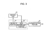
Fig. 3 is a block diagram that illustrates a functional configuration of the control portion in an authentication mode. -
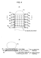
Fig. 4 is a schematic diagram that illustrates a configuration of an imaging unit. -
Fig. 5 is a schematic diagram that illustrates a relationship between an illumination direction and a finger placement surface. -
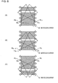
Fig. 6 is a schematic diagram for use in describing assignment of an illumination target to a region corresponding to a scan line. -
Fig. 7 is a schematic diagram for use in describing a distance between the location of the finger placement surface and the location of an illuminating portion for total illumination and for partial illumination. -
Fig. 8 is a schematic diagram that illustrates an optical system according to another embodiment. - An embodiment in which the present invention is used is described below about the drawings.
-
Fig. 1 illustrates a general configuration of anauthentication apparatus 1 according to the present embodiment. Thisauthentication apparatus 1 is configured such that anoperating portion 11, animaging unit 12, amemory 13, aninterface 14, and anotification portion 15 are connected to acontrol portion 10 through a bus 16. - The
control portion 10 is configured as a computer containing a central processing unit (CPU) controlling the whole of theauthentication apparatus 1, a read-only memory (ROM) in which various programs and setting information are stored, and a random-access memory (RAM) serving as a work memory of the CPU. - In response to a user operation, a command COM1 for a mode for registering a vein of a finger of a user being a registration target (hereinafter, the mode is referred to as a blood-vessel registration mode, and the registration target user is referred to as a registrant) or a command COM2 for a mode for determining whether a user is a registrant or not (hereinafter referred to as an authentication mode) is input from the
operating portion 11 into thecontrol portion 10. - The
control portion 10 determines a mode to be executed on the basis of the command COM1 or COM2, appropriately controls theimaging unit 12, thememory 13, theinterface 14, and thenotification portion 15 on the basis of a program corresponding to a result of the determination, and executes the blood-vessel registration mode or the authentication mode. - The
imaging unit 12 illuminates a surface on which a finger can be placed (hereinafter referred to as a finger placement surface) with imaging light and outputs image data relating to an image containing a vein inside the finger placed on the finger placement surface (hereinafter referred to as a venous image) to thecontrol portion 10. - The
memory 13 can be a flash memory, for example, and stores or reads data specified by thecontrol portion 10. - The
interface 14 exchanges various kinds of data with an external device connected through a predetermined transmission line. - The
notification portion 15 includes adisplay portion 15a and anaudio output portion 15b. Thedisplay portion 15a displays text and graphics based on display data supplied from thecontrol portion 10 on its display screen. On the other hand, theaudio output portion 15b outputs, from a speaker, audio based on audio data supplied from thecontrol portion 10. - Next, the blood-vessel registration mode is described. When determining the blood-vessel registration mode as the mode to be executed, the
control portion 10 notifies that a finger should be placed on the finger placement surface through thenotification portion 15, and after that, as illustrated inFig. 2 , thecontrol portion 10 functions as adriving portion 21, a vein-information extracting portion 22, and aregistration portion 23. - In this case, the
driving portion 21 generates a predetermined control signal and drives theimaging unit 12 in accordance with the control signal. - The vein-
information extracting portion 22 extracts information relating to a vein shown in a venous image (hereinafter referred to as vein information) on the basis of image data supplied from theimaging unit 12. As this vein information, various elements, for example, a venous image from which the center of a blood-vessel width or the peak of luminance is extracted, all or part of the center of the blood-vessel width or the peak of luminance, or a parameter subjected to curve fitting to a blood vessel can be employed. - The
registration portion 23 acquires vein information extracted by the vein-information extracting portion 22 and registers it by storing it as registration data into thememory 13. - In such a way, the
control portion 10 can execute the blood-vessel registration mode. - Next, the authentication mode is described. When determining the authentication mode as the mode to be executed, the
control portion 10 notifies that a finger should be placed on the finger placement surface through thenotification portion 15, and after that, as illustrated inFig. 3 , in which like parts are identified by the same reference numerals as inFig. 2 , thecontrol portion 10 functions as thedriving portion 21, thefinger placement surface 22, and anauthentication portion 31. - In this case, the driving
portion 21 drives theimaging unit 12, and thefinger placement surface 22 extracts vein information on the basis of image data supplied from theimaging unit 12. - The
authentication portion 31 checks the vein information extracted by thefinger placement surface 22 against the vein information registered as registration data in thememory 13. - And, when the degree of correlation of the vein information obtained as a result of this checking is less than a predetermined level, the
authentication portion 31 determines that the person cannot be authenticated as a registrant. In this case, theauthentication portion 31 visually and aurally notifies that the person cannot be authenticated as a registrant through thedisplay portion 15a and theaudio output portion 15b. - On the other hand, when the degree of correlation of the vein information obtained as a result of the checking is greater than or equal to the predetermined level, the
authentication portion 31 determines that the person can be authenticated as a registrant. In this case, theauthentication portion 31 sends data for starting execution of predetermined processing to a device connected to theinterface 14. This device performs processing to be executed for successful authentication, as the predetermined processing, for example, closing a door in a fixed period of time or clearing an operational mode of a restriction target. - In such a way, this
control portion 10 can execute the authentication mode. - Next, the
imaging unit 12 is described. - The
imaging unit 12 is a unit that can also be incorporated into a portable device, such as a cellular phone. - An example of the configuration of the
imaging unit 12 is described usingFig. 4(A) and Fig. 4(B) , which illustrates the X-Y cross section ofFig. 4(A) . For this example ofFig. 4 , theimaging unit 12 includes animaging portion 12A containing anarea image sensor 41 and amicrolens array 42 and an illuminatingportion 12B containing a plurality oflight sources 431 to 43n and a plurality ofprisms 441 to 44n. - The
area image sensor 41 includes an imaging element having an imaging surface in which a plurality of light receiving elements are arranged in a grid-like fashion. Thearea image sensor 41 is controlled by the driving portion 21 (Fig. 2 ,Fig. 3 ) so as to sequentially perform imaging for each light receiving element on a scan line. The imaging surface of thisarea image sensor 41 is arranged at a location spaced away by a predetermined distance from the back side of the finger placement surface so as to be opposed thereto. - The
microlens array 42 includes a plate member having objective lenses arranged in a grid-like fashion, and each of the objective lenses guides light incident from its light incident surface to the imaging surface of thearea image sensor 41. In this present embodiment, a surface of themicrolens array 42 that is adjacent to the light incident surface of the objective lens is the finger placement surface. - In the case of this present embodiment, the surface of the
microlens array 42 that is adjacent to the light incident surface of the objective lens is the finger placement surface. In this case, when a finger is placed on the finger placement surface, ambient light (light in atmosphere, such as visible light) other than light obtained through the inside of the finger from the light source (near-infrared light) does not substantially enter the light incident surface covered with the surface of the finger. Accordingly, themicrolens array 42 can guide near-infrared light that contains a small noise component resulting from the ambient light to the imaging surface of thearea image sensor 41. - The
light sources 431 to 43n and theprisms 441 to 44n are disposed on the same direction as the side at which thearea image sensor 41 is disposed with respect to a vein plexus inside a finger placed on the finger placement surface (light input surface). - In this example of
Fig. 4 , as is clear fromFig. 4(B) , thelight sources 431 to 43n and theprisms 441 to 44n are disposed in, of a first area adjacent to the finger placement surface and a second area opposite to the finger placement surface, the first and second areas being divided with reference to a vein plexus inside a finger placed on the finger placement surface (light input surface), the first area, where thearea image sensor 41 is disposed. - Among the
light sources 431 to 43n and theprisms 441 to 44n, two of them serving as one set are arranged along the longitudinal direction of the finger placed on the finger placement surface (light input surface) so as to sandwich the finger placement surface (light input surface). - Each of the
light sources 431 to 43n outputs near-infrared light having a wavelength contained in a wavelength band (700 [nm] to 900 [nm]) having a characteristic of being specifically absorbed in both deoxygenated hemoglobin and oxygenated hemoglobin. Theselight sources 431 to 43n are covered with a blocking member SL covering a section other than a section where theprisms 441 to 44n are disposed. - On the other hand, the
prisms 441 to 44n illuminates a section behind a vein plexus inside a finger when the finger is placed on the finger placement surface and above the finger placement surface (light input surface) with near-infrared light output from the correspondinglight sources 431 to 43n through the blocking member SL. - The vein plexus is contained in the intermediate layer (dermal layer) of a three-layer structure (epidermal layer, dermal layer, subcutaneous tissue layer). The dermal layer has a thickness of 2 to 3 [mm] from a location of 0.1 to 0.3 [mm] from the surface of a finger. From this, if a section spaced away from the finger placement surface by approximately 3.5 [mm] or more in its horizontal direction is an illumination target, the subcutaneous tissue layer being above the dermal layer when a finger is placed on the finger placement surface (light input surface), that is, a section behind the vein plexus can be illuminated with near-infrared light.
- Specifically, as illustrated in
Fig. 5 , for example, theprisms 441 to 44n are configured such that a section behind the vein plexus is illuminated with light from a direction having an angle θ with respect to the finger placement surface (light input surface). This angle θ is set at any angle in the range of 30[°] to 60[°]. Incidentally, for the sake of convenience,Fig. 5 illustrates only an incident angle of near-infrared light emitted from thelight source 436 through thecorresponding prism 446. - Accordingly, for the
imaging unit 12, when a section behind the vein plexus inside a finger placed on the finger placement surface (light input surface) is illuminated with near-infrared light, the near-infrared light enters the inside of the finger, travels through the vein plexus and epidermal layer by reflection and scattering inside the finger, and enters the light input surface of themicrolens array 42. At this time, a non-vein section inside the finger is in a light state, whereas a vein section is maintained in a dark state because of absorption properties of hemoglobin, and the contrast between the vein section and the non-vein section is sharp, so the near-infrared light entering the light input surface is guided as light for projecting a vein (hereinafter referred to as vein projection light) to the imaging surface of thearea image sensor 41. - In such a way, this
imaging unit 12 can make vein projection light achieving a sharp contract between a vein section and a non-vein section enter theimaging portion 12A by illuminating a section behind a vein plexus inside a finger using the illuminatingportion 12B, and therefore, a blood vessel inside a finger can be faithfully represented. - In addition to such a configuration, the illuminating
portion 12B in thisimaging unit 12 is configured such that not the whole of a space corresponding to a section behind a vein of a finger placed on the finger placement surface (light input surface) is set as an illumination target, but an illumination target for the space is assigned so as to correspond to one or more scan lines in thearea image sensor 41. - In this present embodiment, as illustrated in
Fig. 6 , for example, the illumination direction, the location, and the like of a pair of theprisms light sources area image sensor 41. - Similarly, the illumination direction, the location, and the like of a pair of
prisms light sources area image sensor 41, ....., and the illumination direction, the position, and the like of a pair ofprisms area image sensor 41 is performed. - In such a way, for this example of
Fig. 6 , with respect to the illumination targets for the corresponding space regions AR1 to ARM behind a vein plexus, to each of the space regions behind a vein being an image formation target to an imaging section (five scan lines) in thearea image sensor 41, the illumination targets in the sets of theprisms light sources - It is to be noted that, although in this example of
Fig. 6 space regions and illumination targets in sets of prisms and light sources are in a one-to-one correspondence, any assignment technique, such as correlating one space region with a plurality of sets of prisms and light sources, can be used as long as illumination targets are assigned to corresponding space regions behind a vein being image formation targets to imaging sections. - On the other hand, the
control portion 10 of thisauthentication apparatus 1 functions as the drivingportion 21 in the blood-vessel registration mode or the authentication mode, and when thecontrol portion 10 drives theimaging unit 12, it makes only part of thelight sources 431 to 43n be lightened while operating together with a scan line being a scan target among the scan lines in thearea image sensor 41. - Specifically, until a scan period in one or more scan lines elapses from a point a predetermined period before the beginning of that scan period, the driving
portion 21 lightens only thelight sources - In the example of
Fig. 6 , when scanning the scan lines from the 21st line to 25th line, for example, the drivingportion 21 lightens only thelight sources - In this case, as is clear from
Fig. 7 , near-infrared light emitted from thelight sources - And, the near-infrared light entering the inside of the finger travels through the vein plexus and the epidermal layer by reflection and scattering inside the finger and enters the scan lines from the 21st line to the 25th line in the
area image sensor 41 from the surface of the finger through themicrolens array 42 as vein projection light, so only the vein section being the current imaging target in the vein plexus inside the finger placed on the finger placement surface is subjected to image formation. - In such a way, it is possible for this
imaging unit 12 to use the space regions AR2 to ARM corresponding to a non-imaging section as an illumination light path for the space region AR1 corresponding to the current imaging section. Accordingly, thisimaging unit 12 can bring the illuminatingportion 12B closer to the finger placement surface (light input surface), as compared with the case where the whole of the space regions AR1 to ARM is an illumination target, so size reduction can be made. - And, as compared with the case where the
light sources 431 to 43n are lightened at the same time, thisimaging unit 12 can more reduce unnecessary power consumption, and additionally, significantly reduce the occurrence of events where vein projection light in the space regions AR2 to ARM other than the space region AR1 is mixed into vein projection light in the space region AR1 being a scan target. Therefore, a blood vessel inside a living body (finger) can be faithfully represented. - In the above configuration, this
authentication apparatus 1 assigns an illumination target for a space region corresponding to a section behind a vein of a finger placed on the finger placement surface (light input surface) such that the illumination target corresponds to one or more scan lines in the area image sensor 41 (Fig. 6 ). - Then, this
authentication apparatus 1 drives thelight sources Fig. 5 ,Fig. 7 ). - Owing to this, this
authentication apparatus 1 can individually perform imaging on a vein inside a finger for each vein section corresponding to the space region AR1, AR2, ..., or ARM corresponding to the scan line. - And, this
authentication apparatus 1 can use a space region corresponding to a non-imaging section, which is not a scan target, as an illumination light path for a space region corresponding to an imaging section being the current scan target, that is, can share the illumination light path in each of thelight sources 431 to 43n within a space between thelight sources 431 to 43n and the finger placement surface, so the illuminatingportion 12B can be brought closer to the finger placement surface (light input surface), as compared with the case where the whole of the space regions AR1 to ARM is an illumination target, and size reduction can be made. - And, for this
authentication apparatus 1, the illumination direction of each of thelight sources Fig. 6 ). - Owing to this, this
authentication apparatus 1 can have a small incident angle of near-infrared light from each of thelight sources 431 to 43n with respect to a finger placed on the finger placement surface, so reflected light from the surface of the finger can be more reduced, as compared with the case where near-infrared light is emitted from a direction opposite to the surface of the finger by 180[°]. Therefore, a blood vessel inside a finger can be more faithfully represented. - With the above configuration, of the finger placement surface, only the space region AR1, AR2, ..., or ARM corresponding to a scan line is individually illuminated with imaging light, and, of blood vessels inside a finger placed on the finger placement surface, blood vessels projected on the imaging surface can be read for each of the blood vessels corresponding to the scan line when it becomes a scan target. This can make a good image quality of the whole of the
area image sensor 41. Hence, theauthentication apparatus 1 capable of expanding a range for use in acquiring a good-quality image can be achieved. - In the above-described embodiment, the case is described where the illuminating
portion 12B is constructed of the plurality ofprisms 441 to 44n and the plurality oflight sources 431 to 43n. However, the present invention is not limited to this case. Other various configurations can be employed as long as an illumination target is assigned to each of the space regions AR1 to ARM corresponding to an imaging section in an imaging element. - For example, moving members allowing rotation movement or translation movement can be disposed so as to sandwich the finger placement surface (light input surface) such that each of the moving members is provided with one light source. On the other hand, the driving
portion 21 can move the moving members operating together with an imaging section in the imaging element such that an illumination target for the light source provided to each of the moving members is the space region AR1, AR2, ..., or ARM corresponding to an imaging section. With this, the plurality ofprisms 441 to 44n can be omitted, so the size can be further reduced. - And, in the case where a configuration of having the plurality of
prisms 441 to 44n and the plurality oflight sources 431 to 43n is used, the arrangement and the like are not limited to the case illustrated inFig. 4 . Other various arrangements and the like can be employed as long as an illumination target is assigned to each of the space regions AR1 to ARM corresponding to imaging sections in an imaging element. - And, in the above-described embodiment, the case is described where one prism is individually provided to one light source. However, the present invention is not intended to enforce a one-to-one correspondence on the correspondence relationship between the light sources and prisms, for example, one prism can be provided to a plurality of light sources.
- Additionally, in the above-described embodiment, the case is described where an angle between the illumination direction of a prism and the finger placement surface is set at any angle in the range from 30[°] to 60[°]. However, the present invention is not limited to this case, and other angle can be set. Specifically, it may preferably be in the range from 30[°] to 45[°]. If it is at least an obtuse angle, surface reflection light can be reduced.
- Additionally, in the above-described embodiment, the case is described where a light source that emits light having a wavelength contained in a wavelength band having a characteristic of being specifically absorbed in both deoxygenated hemoglobin and oxygenated hemoglobin is used. However, the present invention is not limited to this case. A light source that emits light having the other wavelength may also be used, depending to imaging environment.
- Additionally, in the above-described embodiment, the case is described where the
microlens array 41 is used as an optical system. However, the present invention is not limited to this case. For example, as illustrated inFig. 8 , an optical system that bends light incident from the finger placement surface and guides it into thearea image sensor 41 may also be used. It is to be noted that an optical system other than this bending-type optical system or themicrolens array 41 can be employed as appropriate as long as it is an optical system that guides light into thearea image sensor 41. - Additionally, in the above-described embodiment, the case is described where a two-dimensional imaging element (area image sensor 41) is used. However, the present invention is not limited to this case. A one-dimensional imaging element (line image sensor) movable in parallel with the finger placement surface may also be used.
- Additionally, in the above-described embodiment, the case is described where the
authentication apparatus 1 having the imaging function, checking function, and registration function is used. However, the present invention is not limited to this case. A mode in which each function or part of the functions is allocated to a single device depending on the application may also be used. - The present invention can be utilized in the field of biometrics authentication.
Claims (6)
- A vein authentication apparatus characterized by comprising:an imaging portion including a plurality of imaging sections for imaging reflected light reflected from a vein plexus inside a finger and transmitted light transmitted through the vein plexus, the imaging portion being controlled such that the imaging sections perform imaging in different periods;an illuminating portion arranged on the same direction side as the imaging portion with respect to the vein plexus and configured to emit near-infrared light;an authentication processing portion configured to perform authentication processing on the basis of an image imaged by the imaging portion and vein information previously stored; andan illumination control portion configured to control the illuminating portion such that the near-infrared light emitted from the illuminating portion is scattered behind a vein section corresponding to an imaging section being in an imaging period among the plurality of imaging sections.
- The vein authentication apparatus according to Claim 1, characterized in that the illuminating portion includes a plurality of light sources, and
the illumination control portion is configured to control output of the plurality of light sources such that near-infrared light output from part of the plurality of light sources is scattered behind the vein section corresponding to the imaging section being in the imaging period among the plurality of imaging sections. - The vein authentication apparatus according to Claim 2, characterized in that the illumination control portion is configured to restrain illumination by a light source other than the part of the plurality of light sources.
- The vein authentication apparatus according to Claim 1, characterized in that the illuminating portion is configured such that an angle of a section for emitting near-infrared light varies, and
the illumination control portion is configured to make the angle of the section vary such that the near-infrared light emitted from the illuminating portion is scattered behind the vein section corresponding to the imaging section being in the imaging period among the plurality of imaging sections. - An imaging apparatus for vein authentication, the imaging apparatus being characterized by comprising:an imaging portion including a plurality of imaging sections for imaging reflected light reflected from a vein plexus inside a finger and transmitted light transmitted through the vein plexus, the imaging portion being controlled such that the imaging sections perform imaging in different periods;an illuminating portion arranged on the same direction side as the imaging portion with respect to the vein plexus and configured to emit near-infrared light; andan illumination control portion configured to control the illuminating portion such that the near-infrared light emitted from the illuminating portion is scattered behind a vein section corresponding to an imaging section being in an imaging period among the plurality of imaging sections.
- A vein illuminating method of driving an illuminating portion configured to illuminate a vein plexus inside a finger with near-infrared light, the illuminating portion being arranged on the same direction side as an imaging portion, the vein illuminating method being characterized by comprising:controlling the illuminating portion such that, in the case where a plurality of imaging sections in the imaging portion for imaging reflected light reflected from the vein plexus inside the finger and transmitted light transmitted through the vein plexus perform imaging in different periods, the near-infrared light emitted from the illuminating portion is scattered behind a vein section corresponding to an imaging section being in an imaging period among the plurality of imaging sections.
Applications Claiming Priority (2)
| Application Number | Priority Date | Filing Date | Title |
|---|---|---|---|
| JP2007189869A JP4910923B2 (en) | 2007-07-20 | 2007-07-20 | Imaging apparatus, imaging method, and imaging program |
| PCT/JP2008/063333 WO2009014194A1 (en) | 2007-07-20 | 2008-07-17 | Vein authentication device, vein authentication imaging device, and vein illuminating method |
Publications (2)
| Publication Number | Publication Date |
|---|---|
| EP2169612A1 true EP2169612A1 (en) | 2010-03-31 |
| EP2169612A4 EP2169612A4 (en) | 2015-05-06 |
Family
ID=40281441
Family Applications (1)
| Application Number | Title | Priority Date | Filing Date |
|---|---|---|---|
| EP20080778345 Withdrawn EP2169612A4 (en) | 2007-07-20 | 2008-07-17 | VEIN AUTHENTICATION DEVICE, VEIN AUTHENTICATION IMAGING DEVICE, AND VEIN LIGHTING METHOD |
Country Status (7)
| Country | Link |
|---|---|
| US (1) | US8649568B2 (en) |
| EP (1) | EP2169612A4 (en) |
| JP (1) | JP4910923B2 (en) |
| KR (1) | KR101551369B1 (en) |
| CN (1) | CN101743564B (en) |
| TW (1) | TW200917134A (en) |
| WO (1) | WO2009014194A1 (en) |
Cited By (2)
| Publication number | Priority date | Publication date | Assignee | Title |
|---|---|---|---|---|
| CN107657209A (en) * | 2017-07-07 | 2018-02-02 | 杭州电子科技大学 | A kind of template image login mechanism based on finger vein image quality |
| CN111249582A (en) * | 2020-02-04 | 2020-06-09 | 中国计量大学 | Deep vein visualization device and deep vein visualization method based on NIR-Ⅱ light single-pixel imaging |
Families Citing this family (33)
| Publication number | Priority date | Publication date | Assignee | Title |
|---|---|---|---|---|
| US7057256B2 (en) | 2001-05-25 | 2006-06-06 | President & Fellows Of Harvard College | Silicon-based visible and near-infrared optoelectric devices |
| US7442629B2 (en) | 2004-09-24 | 2008-10-28 | President & Fellows Of Harvard College | Femtosecond laser-induced formation of submicrometer spikes on a semiconductor substrate |
| US9673243B2 (en) | 2009-09-17 | 2017-06-06 | Sionyx, Llc | Photosensitive imaging devices and associated methods |
| US8692198B2 (en) | 2010-04-21 | 2014-04-08 | Sionyx, Inc. | Photosensitive imaging devices and associated methods |
| CN103081128B (en) | 2010-06-18 | 2016-11-02 | 西奥尼克斯公司 | High-speed photosensitive device and related method |
| US9496308B2 (en) | 2011-06-09 | 2016-11-15 | Sionyx, Llc | Process module for increasing the response of backside illuminated photosensitive imagers and associated methods |
| JP2014525091A (en) | 2011-07-13 | 2014-09-25 | サイオニクス、インク. | Biological imaging apparatus and related method |
| JP6010898B2 (en) * | 2011-11-16 | 2016-10-19 | ソニー株式会社 | Biological measuring device, biological measuring method, program, and recording medium |
| US11399898B2 (en) | 2012-03-06 | 2022-08-02 | Briteseed, Llc | User interface for a system used to determine tissue or artifact characteristics |
| TWI476702B (en) * | 2012-03-16 | 2015-03-11 | Pixart Imaging Inc | User identification system and method for identifying user |
| CN105308626A (en) * | 2013-01-17 | 2016-02-03 | 西奥尼克斯股份有限公司 | Biometric imaging devices and associated methods |
| EP2946339A4 (en) * | 2013-01-17 | 2016-09-14 | Sionyx Llc | BIOMETRIC IMAGING DEVICES AND ASSOCIATED METHODS |
| WO2014209421A1 (en) | 2013-06-29 | 2014-12-31 | Sionyx, Inc. | Shallow trench textured regions and associated methods |
| EP3122237B1 (en) | 2014-03-25 | 2018-10-17 | Briteseed, LLC | Vessel detector and method of detection |
| KR102302844B1 (en) | 2014-10-23 | 2021-09-16 | 삼성전자주식회사 | Method and apparatus certifying user using vein pattern |
| ES2907824T3 (en) | 2015-02-19 | 2022-04-26 | Briteseed Llc | System to determine the edge of a glass |
| US10820838B2 (en) | 2015-02-19 | 2020-11-03 | Briteseed, Llc | System for determining vessel size using light absorption |
| CN104715182A (en) * | 2015-03-11 | 2015-06-17 | 识益生物科技(北京)有限公司 | Mobile terminal with digital vein recognition device and digital vein recognition method |
| US10679081B2 (en) * | 2015-07-29 | 2020-06-09 | Industrial Technology Research Institute | Biometric device and wearable carrier |
| CN111242092A (en) * | 2015-07-29 | 2020-06-05 | 财团法人工业技术研究院 | Biological identification device and wearable carrier |
| US9722793B2 (en) | 2015-09-09 | 2017-08-01 | Microsoft Technology Licensing, Llc | Personal identification via acoustically stimulated biospeckles |
| JP7057277B2 (en) | 2015-10-08 | 2022-04-19 | ブライトシード・エルエルシー | A system for determining vascular size and its method |
| CN105512636A (en) * | 2015-12-19 | 2016-04-20 | 南京福瑞林生物科技有限公司 | Living fingerprint identification device and living fingerprint identification method |
| CN105701454A (en) * | 2016-01-06 | 2016-06-22 | 深圳市亚略特生物识别科技有限公司 | Vein identity authentication device and electronic system |
| JP6951348B2 (en) | 2016-02-12 | 2021-10-20 | ブライトシード・エルエルシーBriteseed,Llc | Systems and methods for determining organizational characteristics |
| EP3506815B1 (en) | 2016-08-30 | 2022-03-09 | Briteseed, LLC | Optical surgical system with non-parallel jaws with angular distortion compensation |
| EP3678535B1 (en) | 2017-09-05 | 2021-11-03 | Briteseed, LLC | System and method used to determine tissue and/or artifact characteristics |
| US11200408B2 (en) * | 2017-11-28 | 2021-12-14 | Fingerprint Cards Anacatum Ip Ab | Biometric imaging system and method for controlling the system |
| JP7313353B2 (en) | 2017-12-22 | 2023-07-24 | ブライトシード・エルエルシー | Miniature system used to determine tissue or artifact properties |
| EP3902471B1 (en) | 2018-12-30 | 2024-09-18 | Briteseed, LLC | A system used to detect or differentiate tissue or an artifact |
| JP7469871B2 (en) | 2019-12-04 | 2024-04-17 | 株式会社日立製作所 | Photography and authentication devices |
| CN111310742B (en) * | 2020-04-20 | 2023-08-01 | 青岛海泰新光科技股份有限公司 | Ultrathin fingerprint acquisition device |
| USD962239S1 (en) * | 2020-08-20 | 2022-08-30 | Amazon Technologies, Inc. | Pedestal scanner |
Family Cites Families (34)
| Publication number | Priority date | Publication date | Assignee | Title |
|---|---|---|---|---|
| US5737439A (en) * | 1996-10-29 | 1998-04-07 | Smarttouch, Llc. | Anti-fraud biometric scanner that accurately detects blood flow |
| JP3617476B2 (en) * | 2001-07-19 | 2005-02-02 | 株式会社日立製作所 | Finger authentication device |
| JP4499341B2 (en) * | 2002-05-09 | 2010-07-07 | ソニー株式会社 | Biometric authentication device and biometric authentication method |
| EP1503330B1 (en) | 2002-05-09 | 2010-06-02 | Sony Corporation | Method of detecting biological pattern, biological pattern detector, method of biological certificate and biological certificate apparatus |
| JP3972779B2 (en) * | 2002-09-20 | 2007-09-05 | 株式会社日立製作所 | Personal authentication device |
| JP4236214B2 (en) * | 2003-08-01 | 2009-03-11 | バイオニクス株式会社 | Personal authentication device |
| JP4546169B2 (en) * | 2004-06-28 | 2010-09-15 | 富士通株式会社 | An imaging device for palm authentication |
| JP4556111B2 (en) * | 2004-09-02 | 2010-10-06 | ソニー株式会社 | Information processing device |
| JP4626801B2 (en) * | 2004-09-02 | 2011-02-09 | ソニー株式会社 | Imaging device |
| AT413896B (en) * | 2004-09-08 | 2006-07-15 | Nanoident Technologies Ag | DEVICE FOR DETECTING A FINGERPRINT |
| WO2006041780A1 (en) * | 2004-10-04 | 2006-04-20 | Validity Sensors, Inc. | Fingerprint sensing assemblies comprising a substrate |
| CN101044493B (en) * | 2004-10-22 | 2011-05-04 | 皇家飞利浦电子股份有限公司 | Biometrics-based identification method and apparatus |
| JP4423557B2 (en) * | 2004-11-19 | 2010-03-03 | ソニー株式会社 | Authentication device, authentication method and program, and authentication information registration device |
| WO2006067226A2 (en) * | 2004-12-22 | 2006-06-29 | Dilab I Lund Ab | Biometric identification of laboratory animals |
| JP4736502B2 (en) | 2005-03-30 | 2011-07-27 | 株式会社日立製作所 | Personal authentication device, personal authentication method |
| KR100927757B1 (en) * | 2005-06-13 | 2009-11-20 | 가부시키가이샤 히타치세이사쿠쇼 | Information portable terminal |
| JP4704129B2 (en) * | 2005-06-30 | 2011-06-15 | 富士通株式会社 | Biometric authentication method, biometric authentication apparatus, and blood vessel image reading apparatus |
| JP4622763B2 (en) * | 2005-09-14 | 2011-02-02 | 日本電気株式会社 | Mobile communication terminal device and authentication method |
| JP2007148950A (en) * | 2005-11-30 | 2007-06-14 | Hitachi Ltd | Information processing device |
| JP2007206991A (en) * | 2006-02-02 | 2007-08-16 | Hitachi Ltd | Biological information processing apparatus and biological information processing program |
| US20070201727A1 (en) * | 2006-02-13 | 2007-08-30 | Precor Incorporated | User identification for fitness equipment |
| JP4952026B2 (en) * | 2006-03-31 | 2012-06-13 | 株式会社日立製作所 | Biometric information authentication apparatus and authentication method |
| JP2008073377A (en) * | 2006-09-25 | 2008-04-03 | Hitachi Ltd | Finger vein authentication input device |
| US8280118B2 (en) * | 2006-11-21 | 2012-10-02 | Hitachi, Ltd. | Biometrics authentication device and portable terminal |
| JP4306744B2 (en) * | 2007-03-01 | 2009-08-05 | ソニー株式会社 | Biometric authentication device |
| US8098900B2 (en) * | 2007-03-06 | 2012-01-17 | Honeywell International Inc. | Skin detection sensor |
| JP2008287432A (en) * | 2007-05-16 | 2008-11-27 | Sony Corp | Vein pattern management system, vein pattern registration device, vein pattern authentication device, vein pattern registration method, vein pattern authentication method, program, and vein data structure |
| JP4941311B2 (en) * | 2008-01-09 | 2012-05-30 | ソニー株式会社 | mouse |
| JP5292821B2 (en) * | 2008-01-16 | 2013-09-18 | ソニー株式会社 | Vein image acquisition device and vein image acquisition method |
| JP4748257B2 (en) * | 2008-08-04 | 2011-08-17 | ソニー株式会社 | Biometric authentication device |
| JP5326792B2 (en) * | 2009-05-14 | 2013-10-30 | ソニー株式会社 | Vein imaging device, positional deviation interpolation method and program |
| JP4548542B1 (en) * | 2009-06-30 | 2010-09-22 | ソニー株式会社 | Information processing apparatus, information processing method, and program |
| KR101084894B1 (en) * | 2009-09-16 | 2011-11-17 | 삼성전기주식회사 | Vein authentication device using total reflection |
| JP5895201B2 (en) * | 2011-07-29 | 2016-03-30 | パナソニックIpマネジメント株式会社 | Vehicle opening / closing body control device |
-
2007
- 2007-07-20 JP JP2007189869A patent/JP4910923B2/en not_active Expired - Fee Related
-
2008
- 2008-05-27 TW TW097119560A patent/TW200917134A/en not_active IP Right Cessation
- 2008-07-17 CN CN2008800246485A patent/CN101743564B/en not_active Expired - Fee Related
- 2008-07-17 EP EP20080778345 patent/EP2169612A4/en not_active Withdrawn
- 2008-07-17 US US12/668,973 patent/US8649568B2/en not_active Expired - Fee Related
- 2008-07-17 WO PCT/JP2008/063333 patent/WO2009014194A1/en not_active Ceased
- 2008-07-17 KR KR1020107001097A patent/KR101551369B1/en not_active Expired - Fee Related
Non-Patent Citations (1)
| Title |
|---|
| See references of WO2009014194A1 * |
Cited By (4)
| Publication number | Priority date | Publication date | Assignee | Title |
|---|---|---|---|---|
| CN107657209A (en) * | 2017-07-07 | 2018-02-02 | 杭州电子科技大学 | A kind of template image login mechanism based on finger vein image quality |
| CN107657209B (en) * | 2017-07-07 | 2020-07-28 | 杭州电子科技大学 | Template image registration mechanism based on finger vein image quality |
| CN111249582A (en) * | 2020-02-04 | 2020-06-09 | 中国计量大学 | Deep vein visualization device and deep vein visualization method based on NIR-Ⅱ light single-pixel imaging |
| CN111249582B (en) * | 2020-02-04 | 2022-03-11 | 中国计量大学 | Deep vein visualization device and deep vein visualization method based on NIR-Ⅱ light single-pixel imaging |
Also Published As
| Publication number | Publication date |
|---|---|
| TW200917134A (en) | 2009-04-16 |
| CN101743564A (en) | 2010-06-16 |
| KR20100038375A (en) | 2010-04-14 |
| KR101551369B1 (en) | 2015-09-08 |
| WO2009014194A1 (en) | 2009-01-29 |
| JP4910923B2 (en) | 2012-04-04 |
| JP2009026142A (en) | 2009-02-05 |
| EP2169612A4 (en) | 2015-05-06 |
| TWI373002B (en) | 2012-09-21 |
| US8649568B2 (en) | 2014-02-11 |
| US20100208949A1 (en) | 2010-08-19 |
| CN101743564B (en) | 2013-12-11 |
Similar Documents
| Publication | Publication Date | Title |
|---|---|---|
| US8649568B2 (en) | Vein authentication apparatus, imaging apparatus for vein authentication, and vein illuminating method | |
| CN101866419B (en) | personal authentication device | |
| CN101030250B (en) | Cash register | |
| CN109426812B (en) | Device for simultaneous contact-based acquisition of hand and foot impressions | |
| US20170124376A1 (en) | Infrared fluorescent backlight for optical touch and fingerprint | |
| US20200134282A1 (en) | Image processing method, device, electronic apparatus and storage medium | |
| US20080317293A1 (en) | Finger vein authentication apparatus and information processing apparatus | |
| JP2003030632A (en) | Finger authentication device | |
| JP6870709B2 (en) | Information reader | |
| CN101425130A (en) | Finger vein authentication device | |
| WO2001065471A1 (en) | Method and apparatus for distinguishing a human finger from a reproduction of a fingerprint | |
| US20150062319A1 (en) | Authentication apparatus, prism member for authentication and authentication method | |
| KR20080106483A (en) | Vein authentication device | |
| JP6182830B2 (en) | Electronics | |
| US20210271845A1 (en) | Apparatus for Optically Directly Recording Skin Prints for Mobile Applications | |
| CN103454768A (en) | Imaging device and electronic apparatus | |
| US9619690B2 (en) | Authentication apparatus, prism member for authentication and authentication method | |
| US20120087555A1 (en) | Imaging device having a prismatic element | |
| US20130070073A1 (en) | Biological imaging device and biological imaging method | |
| JP2013225324A (en) | Personal authentication device, image processor, terminal and system | |
| US20150054932A1 (en) | Authentication apparatus, prism member for authentication and authentication method | |
| US11721125B2 (en) | Device for displaying information and for capturing autopodial impressions | |
| JP2023182080A (en) | biometric authentication device | |
| WO2010067545A1 (en) | Biometric information acquisition device, biometric authentication device, light guide, and image acquisition device | |
| JP2006073223A (en) | Surface light emitting device and liquid crystal display device |
Legal Events
| Date | Code | Title | Description |
|---|---|---|---|
| PUAI | Public reference made under article 153(3) epc to a published international application that has entered the european phase |
Free format text: ORIGINAL CODE: 0009012 |
|
| 17P | Request for examination filed |
Effective date: 20100107 |
|
| AK | Designated contracting states |
Kind code of ref document: A1 Designated state(s): AT BE BG CH CY CZ DE DK EE ES FI FR GB GR HR HU IE IS IT LI LT LU LV MC MT NL NO PL PT RO SE SI SK TR |
|
| AX | Request for extension of the european patent |
Extension state: AL BA MK RS |
|
| DAX | Request for extension of the european patent (deleted) | ||
| RA4 | Supplementary search report drawn up and despatched (corrected) |
Effective date: 20150410 |
|
| RIC1 | Information provided on ipc code assigned before grant |
Ipc: G06K 9/00 20060101ALI20150405BHEP Ipc: G06T 1/00 20060101AFI20150405BHEP |
|
| 17Q | First examination report despatched |
Effective date: 20150821 |
|
| GRAP | Despatch of communication of intention to grant a patent |
Free format text: ORIGINAL CODE: EPIDOSNIGR1 |
|
| STAA | Information on the status of an ep patent application or granted ep patent |
Free format text: STATUS: GRANT OF PATENT IS INTENDED |
|
| INTG | Intention to grant announced |
Effective date: 20191111 |
|
| STAA | Information on the status of an ep patent application or granted ep patent |
Free format text: STATUS: THE APPLICATION IS DEEMED TO BE WITHDRAWN |
|
| 18D | Application deemed to be withdrawn |
Effective date: 20200603 |