EP2169377A2 - Vibration data acquisition using an universal serial bus (USB) interface - Google Patents
Vibration data acquisition using an universal serial bus (USB) interface Download PDFInfo
- Publication number
- EP2169377A2 EP2169377A2 EP09169714A EP09169714A EP2169377A2 EP 2169377 A2 EP2169377 A2 EP 2169377A2 EP 09169714 A EP09169714 A EP 09169714A EP 09169714 A EP09169714 A EP 09169714A EP 2169377 A2 EP2169377 A2 EP 2169377A2
- Authority
- EP
- European Patent Office
- Prior art keywords
- data
- usb
- communication device
- electrical signal
- vibrations
- Prior art date
- Legal status (The legal status is an assumption and is not a legal conclusion. Google has not performed a legal analysis and makes no representation as to the accuracy of the status listed.)
- Ceased
Links
- 230000001143 conditioned effect Effects 0.000 claims abstract description 44
- 238000004891 communication Methods 0.000 claims abstract description 37
- 238000013500 data storage Methods 0.000 claims abstract description 30
- 238000005070 sampling Methods 0.000 claims abstract description 17
- 230000003750 conditioning effect Effects 0.000 claims abstract description 13
- 239000000872 buffer Substances 0.000 claims description 23
- 238000012545 processing Methods 0.000 claims description 6
- 230000004044 response Effects 0.000 claims description 3
- 238000000034 method Methods 0.000 description 5
- 238000012360 testing method Methods 0.000 description 4
- 238000012546 transfer Methods 0.000 description 3
- 230000004075 alteration Effects 0.000 description 1
- 238000004590 computer program Methods 0.000 description 1
- 238000001914 filtration Methods 0.000 description 1
- 230000006266 hibernation Effects 0.000 description 1
- 238000005259 measurement Methods 0.000 description 1
- 230000008569 process Effects 0.000 description 1
- 239000007787 solid Substances 0.000 description 1
- 238000006467 substitution reaction Methods 0.000 description 1
Images


Classifications
-
- G—PHYSICS
- G01—MEASURING; TESTING
- G01M—TESTING STATIC OR DYNAMIC BALANCE OF MACHINES OR STRUCTURES; TESTING OF STRUCTURES OR APPARATUS, NOT OTHERWISE PROVIDED FOR
- G01M15/00—Testing of engines
- G01M15/04—Testing internal-combustion engines
- G01M15/12—Testing internal-combustion engines by monitoring vibrations
-
- G—PHYSICS
- G01—MEASURING; TESTING
- G01H—MEASUREMENT OF MECHANICAL VIBRATIONS OR ULTRASONIC, SONIC OR INFRASONIC WAVES
- G01H1/00—Measuring characteristics of vibrations in solids by using direct conduction to the detector
- G01H1/003—Measuring characteristics of vibrations in solids by using direct conduction to the detector of rotating machines
-
- G—PHYSICS
- G01—MEASURING; TESTING
- G01M—TESTING STATIC OR DYNAMIC BALANCE OF MACHINES OR STRUCTURES; TESTING OF STRUCTURES OR APPARATUS, NOT OTHERWISE PROVIDED FOR
- G01M13/00—Testing of machine parts
- G01M13/02—Gearings; Transmission mechanisms
- G01M13/028—Acoustic or vibration analysis
-
- G—PHYSICS
- G01—MEASURING; TESTING
- G01M—TESTING STATIC OR DYNAMIC BALANCE OF MACHINES OR STRUCTURES; TESTING OF STRUCTURES OR APPARATUS, NOT OTHERWISE PROVIDED FOR
- G01M13/00—Testing of machine parts
- G01M13/04—Bearings
- G01M13/045—Acoustic or vibration analysis
Definitions
- the subject matter disclosed herein relates generally to a portable data collector and analyzer for diagnosing machinery and, more particularly, to a portable data collector and analyzer with a Universal Serial Bus (USB) interface for transferring data at a high-rate.
- USB Universal Serial Bus
- rotating machinery diagnostics has required large and bulky test equipment along with a large amount of data to properly diagnose machine vibration problems.
- the bulky test equipment must be operated close to a power source and in a harsh environment.
- a device must be designed to have the same technical capabilities as the large and bulky test equipment, but must be compact in size and have the ability to be operated with a battery for at least 6 to 8 hours.
- a system for collecting and analyzing vibration data includes at least one sensor for sensing vibrations and producing an electrical signal corresponding to the sensed vibrations; a Universal Serial Bus (USB) communication device for receiving the electrical signal corresponding to the sensed vibrations from the at least one sensor and conditioning and sampling the electrical signal to produce a conditioned signal; and a data collector for receiving the conditioned signal and storing the conditioned signal in a data storage device.
- USB Universal Serial Bus
- a vibration data acquisition system in another embodiment, includes at least one sensor for sensing vibrations and producing an electrical signal corresponding to the sensed vibrations; a Universal Serial Bus (USB) communication device for receiving the electrical signal corresponding to the sensed vibrations from the at least one sensor and conditioning and sampling the electrical signal to produce a conditioned signal; and a data collector for receiving the conditioned signal and storing the conditioned signal in a data storage device, the data collector including a power supply configured to supply power to the USB communication device.
- USB Universal Serial Bus
- a portable vibration data acquisition system includes at least one sensor for sensing vibrations and producing an electrical signal corresponding to the sensed vibrations; a Universal Serial Bus (USB) communication device for receiving the electrical signal corresponding to the sensed vibrations from the at least one sensor and conditioning and sampling the electrical signal to produce a conditioned signal; a data collector for receiving the conditioned signal and storing the conditioned signal in a data storage device, the data collector includes a power supply configured to supply power to the USB communication device; and at least one set of buffers for temporarily storing the conditioned signal before being stored in the data storage device.
- USB Universal Serial Bus
- Various embodiments are directed to a system for collecting and analyzing vibration data that includes a USB interface as the primary communication link between sensors and a computer interface of the system in accordance with one embodiment. Further, in these embodiments, the system continuously takes raw analog vibration signals from multiple sensors and converts the signals into self describing data objects (e.g., digital data) for storage onto a data storage device (e.g., non-volatile solid state device) while maintaining a high rate of data transfer in accordance with one exemplary embodiment.
- the USB interface consumes low amounts of power and still effectively provides a high rate of data throughput.
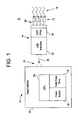
- Figure 1 illustrates a portable vibration data acquisition system 10 in accordance with one exemplary embodiment of the present invention.
- the system includes one or more sensors 12, a USB communications device 14, and a data collector device 16.
- the one or more sensors 12 will be described herein as a plurality of sensors 12. However, it should be understood that a single sensor can be used in exemplary embodiments of the present invention.
- the plurality of sensors 12 is configured to continuously sense vibrations or raw analog vibration signals, which are depicted as lines 18, produced by an operating machine (not shown).
- the plurality of sensors 12 produce electrical signals corresponding to the raw analog vibration signals or sensed vibrations.
- One end of each of the plurality of sensors 12 is placed against the machine to sense vibrations, which are often indicative of the condition of the machine, while another end of each of the plurality of sensors 12 is correspondingly coupled to the USB communications device 14 via signal lines 20.
- signal lines 20 are depicted as single lines, it should be understood that each of these single lines may also represent twisted wire pairs or wireless communication.
- other suitable communication means for transmitting the sensed vibration signals can be used in other exemplary embodiments and should not be limited to the configurations illustrated herein.
- each of the plurality of sensors 12 includes a vibration transducer.
- Each of the plurality of sensors 12 may also include a proximity sensor, velocimeter, accelerometer, or any other sensing device that is capable of sensing vibrations in other exemplary embodiments.
- Figure 1 illustrates four sensors for sensing vibrations. However, it should be understood that less or more than four sensors can be used to sense vibrations depending on the application and should not be limited to the configuration as shown.
- the USB communication device 14 includes a USB interface 22 and a digital signal processor (DSP) 24 or a field-programmable gate array (FPGA).
- DSP digital signal processor
- FPGA field-programmable gate array
- One end of the USB communication device 14 is coupled to the plurality of sensors 12 while the other end of the USB communication device 14 is coupled to the data collector 16 via a USB connector 26.
- the USB communication device 14 operably receives the electrical signals from the sensors and is configured to transfer vibration data to the data collector 16 via the USB connector 26.
- the DSP 24 receives the electrical signals from the sensors 12 for conditioning and sampling the electrical signals to produce a conditioned signal and the USB interface 22 transfers the conditioned signal to the data collector 16 through the USB connector 26.
- the DSP 24 is configured to sample the raw analog vibration signals at different sampling rates in accordance with one exemplary embodiment.
- the USB interface 22 can be any conventional USB interface 22 suitable for transferring data to the data collector 16 at a high-rate while having the power consumption equivalent to more traditional interfaces (i.e. Ethernet, RS-232).
- the USB interface 22 has the ability to be suspended to the data collector 16 when not in use and does not require a separate power source to operate or internet service, which can be difficult to obtain at times.
- a continuous digital vibration data flow which is depicted by arrow 28, can be formed between the USB interface 22 and the data collector 16.
- the DSP 24 includes one or more analog to digital converters (not shown) for converting the analog vibration data to self-describing data objects or digital vibration data.
- the DSP 24 is configured to construct vibration data packets out of the digital vibration data as conditioned signals, which are sent to the data collector 16 by the USB interface 22 for storage and/or further processing.
- the data collector 16 can be any conventional data collecting device suitable for collecting vibration data.
- the data collector 16 includes a housing 30 and a data storage device 32 for storing vibration data.
- the data collector 16 is portable.
- the data collector 16 can be a stationary device in other exemplary embodiments.
- the data storage device 32 is a solid-state device disposed within the housing 30.
- any suitable data storage type can be used in accordance with exemplary embodiments of the present invention.
- the data collector 16 includes a central processing unit (CPU) 34 for controlling the operations of the data collector 16.
- CPU central processing unit
- the CPU 34 parses the vibration data packets and archives the vibration data to the appropriate directory in the data storage device 32 of the data collector 16. In another example, the CPU 34 performs various measurements (e.g., decimation on conditioned signal, digital filtering, etc.) and stores the output in the data storage device 32.
- the CPU 34 can be any conventional processing unit configured for carrying out the methods and/or functions described herein.
- the CPU 34 comprises a combination of hardware and/or software/firmware with a computer program that, when loaded and executed, permits the CPU 34 to operate such that it carries out the methods described herein.
- the data collector 16 further includes a power supply 36 for providing electrical power to the components in the system 10.
- the power supply 36 is a rechargeable battery that can hold enough power to allow the user to complete a test without the need to recharge the power supply 36 while still being compact in size.
- the power supply 36 can be a rechargeable battery with a battery life of approximately 6 to 8 hours.
- the power supply 36 can be a non-rechargeable battery with a battery life of approximately 6 to 8 hours. It should be understood that the power supply 36 can be any size and hold up to any amounts of electrical power depending on the application and should not be limited to the examples set forth above.
- the power supply 36 of the data collector 16 provides electrical power to the USB communication device 14 and the components thereof via the USB connector 26.
- the USB communication device 14 can be powered up when the data collector 16 is powered up.
- the USB communication device 14 is placed in the same state, thereby further minimizing the consumption of power from the power supply 36.
- the power supply 36 may also effectively power the plurality of sensors 12 in accordance with one embodiment. In an alternate embodiment, the sensors 12 are powered by a separate power source.
- the data collector 16 further includes a first set of buffers 38 for temporarily storing the vibration data packets and a second set of buffers 40 for temporarily storing the parsed vibration data packets before being stored in the data storage device 32 as shown in Figure 2 .
- each conditioned signal from the USB interface 22 is stored in one of the buffers in the first set of buffers 38 in a sequential fashion. For example, one conditioned signal is stored in the first buffer; the next conditioned signal is stored in the second buffer; and so forth.
- the CPU 34 takes the conditioned signals from the first set of buffers 38 one at a time and parses the signals and temporarily stores the parsed signals in the second set of buffers 40 in an orderly fashion.
- the CPU 34 takes the parsed signals from the second set of buffers 40 and archives the parsed signals into the data storage device 32 in an orderly fashion. This process is continuous until all data is saved onto the data storage device 32. It is contemplated that only a single set of buffers is used to temporarily store parsed signals.
- the number of buffer sets may vary depending on the application and should not be limited to the configurations herein. It should be understood that the conditioned signals from the USB interface 14 may also be saved directly onto the data storage device 32 without being parsed in accordance with other exemplary embodiments.
- the plurality of sensors 12 senses vibrations produced by the operating machine.
- the plurality of sensors 12 produce electrical signals corresponding to the raw analog vibration signals.
- the DSP 24 receives the raw analog vibrations and conditions and samples the signals to produce digital vibration data.
- the DSP 24 converts the analog vibration data to digital vibration data utilizing analog to digital converters.
- the DSP 24 constructs vibration data packets out of the digital vibration data as conditioned signals.
- the USB interface 22 sends the conditioned signals (vibration data packets) to the data collector 16.
- the data collector 16 parses the vibration data packets and stores the parsed vibration data packets in the data storage device 32.
Landscapes
- Physics & Mathematics (AREA)
- General Physics & Mathematics (AREA)
- Acoustics & Sound (AREA)
- Chemical & Material Sciences (AREA)
- Engineering & Computer Science (AREA)
- Combustion & Propulsion (AREA)
- Measurement Of Mechanical Vibrations Or Ultrasonic Waves (AREA)
- Information Transfer Systems (AREA)
- Recording Measured Values (AREA)
Abstract
Description
- The subject matter disclosed herein relates generally to a portable data collector and analyzer for diagnosing machinery and, more particularly, to a portable data collector and analyzer with a Universal Serial Bus (USB) interface for transferring data at a high-rate.
- Traditionally, rotating machinery diagnostics has required large and bulky test equipment along with a large amount of data to properly diagnose machine vibration problems. The bulky test equipment must be operated close to a power source and in a harsh environment. A device must be designed to have the same technical capabilities as the large and bulky test equipment, but must be compact in size and have the ability to be operated with a battery for at least 6 to 8 hours.
- In one embodiment according to the present invention, a system for collecting and analyzing vibration data is provided. The system includes at least one sensor for sensing vibrations and producing an electrical signal corresponding to the sensed vibrations; a Universal Serial Bus (USB) communication device for receiving the electrical signal corresponding to the sensed vibrations from the at least one sensor and conditioning and sampling the electrical signal to produce a conditioned signal; and a data collector for receiving the conditioned signal and storing the conditioned signal in a data storage device.
- In another embodiment, a vibration data acquisition system is provided. The portable system includes at least one sensor for sensing vibrations and producing an electrical signal corresponding to the sensed vibrations; a Universal Serial Bus (USB) communication device for receiving the electrical signal corresponding to the sensed vibrations from the at least one sensor and conditioning and sampling the electrical signal to produce a conditioned signal; and a data collector for receiving the conditioned signal and storing the conditioned signal in a data storage device, the data collector including a power supply configured to supply power to the USB communication device.
- In yet another embodiment, a portable vibration data acquisition system is provided. The portable system includes at least one sensor for sensing vibrations and producing an electrical signal corresponding to the sensed vibrations; a Universal Serial Bus (USB) communication device for receiving the electrical signal corresponding to the sensed vibrations from the at least one sensor and conditioning and sampling the electrical signal to produce a conditioned signal; a data collector for receiving the conditioned signal and storing the conditioned signal in a data storage device, the data collector includes a power supply configured to supply power to the USB communication device; and at least one set of buffers for temporarily storing the conditioned signal before being stored in the data storage device.
- Various advantages and features will become more apparent from the following description taken in conjunction with the drawings.
- The subject matter which is regarded as the invention is particularly pointed out and distinctly claimed in the claims at the conclusion of the specification. The foregoing and other objects, features, and advantages of the invention are apparent from the following detailed description taken in conjunction with the accompanying drawings in which:
-
FIG. 1 is a schematic of a vibration data acquisition system having a USB communications device that consumes low amounts of power and enables high data throughput in accordance with an exemplary embodiment of the present invention; -
FIG 2 is a schematic of a vibration data acquisition system having a set of buffers for temporarily storing vibration data before being stored in a data storage device in accordance with an exemplary embodiment of the present invention; and -
FIG 3 is a flow chart of a method for transferring raw analog vibration signals from multiple sensors and converting the signals into self describing data objects for storage onto a data storage device in accordance with an exemplary embodiment of the present invention. - The detailed description explains embodiments of the invention, together with advantages and features, by way of example with reference to the drawings.
- Various embodiments are directed to a system for collecting and analyzing vibration data that includes a USB interface as the primary communication link between sensors and a computer interface of the system in accordance with one embodiment. Further, in these embodiments, the system continuously takes raw analog vibration signals from multiple sensors and converts the signals into self describing data objects (e.g., digital data) for storage onto a data storage device (e.g., non-volatile solid state device) while maintaining a high rate of data transfer in accordance with one exemplary embodiment. The USB interface consumes low amounts of power and still effectively provides a high rate of data throughput.
- For a better understanding of various embodiments of the invention and their operation, turning now to the drawings,
Figure 1 illustrates a portable vibrationdata acquisition system 10 in accordance with one exemplary embodiment of the present invention. The system includes one ormore sensors 12, aUSB communications device 14, and adata collector device 16. For simplistic purposes, the one ormore sensors 12 will be described herein as a plurality ofsensors 12. However, it should be understood that a single sensor can be used in exemplary embodiments of the present invention. - The plurality of
sensors 12 is configured to continuously sense vibrations or raw analog vibration signals, which are depicted aslines 18, produced by an operating machine (not shown). The plurality ofsensors 12 produce electrical signals corresponding to the raw analog vibration signals or sensed vibrations. One end of each of the plurality ofsensors 12 is placed against the machine to sense vibrations, which are often indicative of the condition of the machine, while another end of each of the plurality ofsensors 12 is correspondingly coupled to theUSB communications device 14 viasignal lines 20. Whilesignal lines 20 are depicted as single lines, it should be understood that each of these single lines may also represent twisted wire pairs or wireless communication. Of course, other suitable communication means for transmitting the sensed vibration signals can be used in other exemplary embodiments and should not be limited to the configurations illustrated herein. - In accordance with one non-limiting exemplary embodiment, each of the plurality of
sensors 12 includes a vibration transducer. Each of the plurality ofsensors 12 may also include a proximity sensor, velocimeter, accelerometer, or any other sensing device that is capable of sensing vibrations in other exemplary embodiments.Figure 1 illustrates four sensors for sensing vibrations. However, it should be understood that less or more than four sensors can be used to sense vibrations depending on the application and should not be limited to the configuration as shown. - In accordance with one embodiment, the
USB communication device 14 includes aUSB interface 22 and a digital signal processor (DSP) 24 or a field-programmable gate array (FPGA). One end of theUSB communication device 14 is coupled to the plurality ofsensors 12 while the other end of theUSB communication device 14 is coupled to thedata collector 16 via aUSB connector 26. TheUSB communication device 14 operably receives the electrical signals from the sensors and is configured to transfer vibration data to thedata collector 16 via theUSB connector 26. In particular, the DSP 24 receives the electrical signals from thesensors 12 for conditioning and sampling the electrical signals to produce a conditioned signal and theUSB interface 22 transfers the conditioned signal to thedata collector 16 through theUSB connector 26. The DSP 24 is configured to sample the raw analog vibration signals at different sampling rates in accordance with one exemplary embodiment. - The
USB interface 22 can be anyconventional USB interface 22 suitable for transferring data to thedata collector 16 at a high-rate while having the power consumption equivalent to more traditional interfaces (i.e. Ethernet, RS-232). However, theUSB interface 22 has the ability to be suspended to thedata collector 16 when not in use and does not require a separate power source to operate or internet service, which can be difficult to obtain at times. Thus, a continuous digital vibration data flow, which is depicted byarrow 28, can be formed between theUSB interface 22 and thedata collector 16. - The DSP 24 includes one or more analog to digital converters (not shown) for converting the analog vibration data to self-describing data objects or digital vibration data. In accordance with one embodiment, the DSP 24 is configured to construct vibration data packets out of the digital vibration data as conditioned signals, which are sent to the
data collector 16 by theUSB interface 22 for storage and/or further processing. - The
data collector 16 can be any conventional data collecting device suitable for collecting vibration data. In one embodiment, thedata collector 16 includes ahousing 30 and adata storage device 32 for storing vibration data. In accordance with one non-limiting exemplary embodiment, thedata collector 16 is portable. Of course, thedata collector 16 can be a stationary device in other exemplary embodiments. In accordance with one non-limiting embodiment, thedata storage device 32 is a solid-state device disposed within thehousing 30. Of course, any suitable data storage type can be used in accordance with exemplary embodiments of the present invention. Thedata collector 16 includes a central processing unit (CPU) 34 for controlling the operations of thedata collector 16. In one example, theCPU 34 parses the vibration data packets and archives the vibration data to the appropriate directory in thedata storage device 32 of thedata collector 16. In another example, theCPU 34 performs various measurements (e.g., decimation on conditioned signal, digital filtering, etc.) and stores the output in thedata storage device 32. TheCPU 34 can be any conventional processing unit configured for carrying out the methods and/or functions described herein. In one exemplary embodiment, theCPU 34 comprises a combination of hardware and/or software/firmware with a computer program that, when loaded and executed, permits theCPU 34 to operate such that it carries out the methods described herein. - The
data collector 16 further includes apower supply 36 for providing electrical power to the components in thesystem 10. In one embodiment, thepower supply 36 is a rechargeable battery that can hold enough power to allow the user to complete a test without the need to recharge thepower supply 36 while still being compact in size. For example, thepower supply 36 can be a rechargeable battery with a battery life of approximately 6 to 8 hours. In another example, thepower supply 36 can be a non-rechargeable battery with a battery life of approximately 6 to 8 hours. It should be understood that thepower supply 36 can be any size and hold up to any amounts of electrical power depending on the application and should not be limited to the examples set forth above. - In accordance with one embodiment, the
power supply 36 of thedata collector 16 provides electrical power to theUSB communication device 14 and the components thereof via theUSB connector 26. As such, when theUSB communication device 14 is coupled to thehousing 30 of thedata collector 16, theUSB communication device 14 can be powered up when thedata collector 16 is powered up. When thedata collector 16 is powered down or in hibernation, theUSB communication device 14 is placed in the same state, thereby further minimizing the consumption of power from thepower supply 36. Thepower supply 36 may also effectively power the plurality ofsensors 12 in accordance with one embodiment. In an alternate embodiment, thesensors 12 are powered by a separate power source. - In one exemplary embodiment, the
data collector 16 further includes a first set ofbuffers 38 for temporarily storing the vibration data packets and a second set ofbuffers 40 for temporarily storing the parsed vibration data packets before being stored in thedata storage device 32 as shown inFigure 2 . In this embodiment, each conditioned signal from theUSB interface 22 is stored in one of the buffers in the first set ofbuffers 38 in a sequential fashion. For example, one conditioned signal is stored in the first buffer; the next conditioned signal is stored in the second buffer; and so forth. As the buffers in the first set ofbuffers 38 are being filled or once the first set ofbuffers 38 are full, theCPU 34 takes the conditioned signals from the first set ofbuffers 38 one at a time and parses the signals and temporarily stores the parsed signals in the second set ofbuffers 40 in an orderly fashion. As the buffers in the second set ofbuffers 40 are being filled or once the second set ofbuffers 40 are full, theCPU 34 takes the parsed signals from the second set ofbuffers 40 and archives the parsed signals into thedata storage device 32 in an orderly fashion. This process is continuous until all data is saved onto thedata storage device 32. It is contemplated that only a single set of buffers is used to temporarily store parsed signals. Of course, the number of buffer sets may vary depending on the application and should not be limited to the configurations herein. It should be understood that the conditioned signals from theUSB interface 14 may also be saved directly onto thedata storage device 32 without being parsed in accordance with other exemplary embodiments. - Now referring to
Figure 3 , a method for transferring raw analog vibration signals from multiple sensors and converting the signals into self describing data objects for storage onto a data storage device in accordance with one exemplary embodiment will now be discussed. - At
step 100, the plurality ofsensors 12 senses vibrations produced by the operating machine. The plurality ofsensors 12 produce electrical signals corresponding to the raw analog vibration signals. - At
step 102, theDSP 24 receives the raw analog vibrations and conditions and samples the signals to produce digital vibration data. TheDSP 24 converts the analog vibration data to digital vibration data utilizing analog to digital converters. - At
step 104, theDSP 24 constructs vibration data packets out of the digital vibration data as conditioned signals. - At
step 106, theUSB interface 22 sends the conditioned signals (vibration data packets) to thedata collector 16. - At
step 108, thedata collector 16 parses the vibration data packets and stores the parsed vibration data packets in thedata storage device 32. - While the invention has been described in detail in connection with only a limited number of embodiments, it should be readily understood that the invention is not limited to such disclosed embodiments. Rather, the invention can be modified to incorporate any number of variations, alterations, substitutions or equivalent arrangements not heretofore described, but which are commensurate with the spirit and scope of the invention. Additionally, while various embodiments of the invention have been described, it is to be understood that aspects of the invention may include only some of the described embodiments. Accordingly, the invention is not to be seen as limited by the foregoing description, but is only limited by the scope of the appended claims.
- Various aspects and embodiments of the present invention are now defined by the following numbered clauses:
- 1. A system for collecting and analyzing vibration data, the system comprising:
- at least one sensor for sensing vibrations and producing an electrical signal corresponding to the sensed vibrations;
- a Universal Serial Bus (USB) communication device for receiving the electrical signal corresponding to the sensed vibrations from the at least one sensor and conditioning and sampling the electrical signal to produce a conditioned signal; and
- a data collector for receiving the conditioned signal and storing the conditioned signal in a data storage device.
- 2. The system of
clause 1 further comprising a central processing unit for controlling the operations of the system. - 3. The system of any preceding clause further comprising at least one set of buffers for temporarily storing the conditioned signal before being stored in the data storage device.
- 4. The system of any preceding clause, wherein the USB communication device includes a digital signal processor for conditioning and sampling the electrical signal.
- 5. The system of any preceding clause, wherein the digital signal processor is configured to sample the electrical signal at different sampling rates.
- 6. The system of any preceding clause, wherein the USB communication device includes a USB interface for transferring the conditioned signal to the data collector.
- 7. The system of any preceding clause, wherein the data collector includes a power supply configured to supply power to the USB communication device.
- 8. The system of any preceding clause, wherein each of the plurality of sensors comprises a vibration transducer that produces electrical signals in response to vibrations.
- 9. The system of any preceding clause, wherein the data storage device is a solid-state drive.
- 10. A vibration data acquisition system, comprising:
- at least one sensor for sensing vibrations and producing an electrical signal corresponding to the sensed vibrations;
- a Universal Serial Bus (USB) communication device for receiving the electrical signal corresponding to the sensed vibrations from the at least one sensor and conditioning and sampling the electrical signal to produce a conditioned signal; and
- a data collector for receiving the conditioned signal and storing the conditioned signal in a data storage device, the data collector including a power supply configured to supply power to the USB communication device.
- 11. The system of any preceding clause further comprising a central processing unit for controlling the operations of the system.
- 12. The system of any preceding clause further comprising at least one set of buffers for temporarily storing the conditioned signal before being stored in the data storage device.
- 13. The system of any preceding clause, wherein the USB communication device includes a digital signal processor for conditioning and sampling the electrical signal.
- 14. The system of any preceding clause, wherein the digital signal processor is configured to sample the electrical signal at different sampling rates.
- 15. The system of any preceding clause, wherein the USB communication device includes a USB interface for transferring the conditioned signal to the data collector.
- 16. The system of any preceding clause, wherein the data collector includes a power supply configured to supply power to the USB communication device.
- 17. The system of any preceding clause, wherein each of the plurality of sensors comprises a vibration transducer that produces electrical signals in response to vibrations.
- 18. The system of any preceding clause, wherein the data storage device is a solid-state drive.
- 19. A portable vibration data acquisition system, comprising:
- at least one sensor for sensing vibrations and producing an electrical signal corresponding to the sensed vibrations;
- a Universal Serial Bus (USB) communication device for receiving the electrical signal corresponding to the sensed vibrations from the at least one sensor and conditioning and sampling the electrical signal to produce a conditioned signal;
- a portable data collector for receiving the conditioned signal and storing the conditioned signal in a data storage device, the data collector including a power supply configured to supply power to the USB communication device; and
- at least one set of buffers for temporarily storing the conditioned signal before being stored in the data storage device.
- 20. The system of any preceding clause, wherein the USB communication device includes a digital signal processor for conditioning and sampling the electrical signal, the USB communication device further includes a USB interface for transferring the conditioned signal to the data collector.
Claims (9)
- A system (10) for collecting and analyzing vibration data, the system comprising:at least one sensor (12) for sensing vibrations and producing an electrical signal corresponding to the sensed vibrations;a Universal Serial Bus (USB) communication device (14) for receiving the electrical signal corresponding to the sensed vibrations from the at least one sensor (12) and conditioning and sampling the electrical signal to produce a conditioned signal; anda data collector (16) for receiving the conditioned signal and storing the conditioned signal in a data storage device (32).
- The system (10) of claim 1 further comprising a central processing unit (34) for controlling the operations of the system.
- The system (10) of any preceding claim further comprising at least one set of buffers (38) for temporarily storing the conditioned signal before being stored in the data storage device (32).
- The system (10) of any preceding claim, wherein the USB communication device (14) includes a digital signal processor (24) for conditioning and sampling the electrical signal.
- The system (10) of claim 4, wherein the digital signal processor (24) is configured to sample the electrical signal at different sampling rates.
- The system (10) of any preceding claim, wherein the USB communication device (14) includes a USB interface (22) for transferring the conditioned signal to the data collector (16).
- The system (10) of any preceding claim, wherein the data collector (16) includes a power supply (36) configured to supply power to the USB communication device (14).
- The system (10) of any preceding claim, wherein each of the plurality of sensors (12) comprises a vibration transducer that produces electrical signals in response to vibrations.
- The system (10) of any preceding claim, wherein the data storage device (32) is a solid-state drive.
Applications Claiming Priority (1)
| Application Number | Priority Date | Filing Date | Title |
|---|---|---|---|
| US12/239,106 US7689373B1 (en) | 2008-09-26 | 2008-09-26 | USB vibration data acquisition |
Publications (2)
| Publication Number | Publication Date |
|---|---|
| EP2169377A2 true EP2169377A2 (en) | 2010-03-31 |
| EP2169377A3 EP2169377A3 (en) | 2016-08-17 |
Family
ID=41429679
Family Applications (1)
| Application Number | Title | Priority Date | Filing Date |
|---|---|---|---|
| EP09169714.4A Ceased EP2169377A3 (en) | 2008-09-26 | 2009-09-08 | Vibration data acquisition using an universal serial bus (USB) interface |
Country Status (4)
| Country | Link |
|---|---|
| US (1) | US7689373B1 (en) |
| EP (1) | EP2169377A3 (en) |
| JP (1) | JP2010079903A (en) |
| CN (1) | CN101685032A (en) |
Cited By (1)
| Publication number | Priority date | Publication date | Assignee | Title |
|---|---|---|---|---|
| RU183296U1 (en) * | 2018-04-20 | 2018-09-17 | Общество с ограниченной ответственностью "ДиаТех" | Vibrodiagnostic multi-channel system |
Families Citing this family (9)
| Publication number | Priority date | Publication date | Assignee | Title |
|---|---|---|---|---|
| DK2517473T3 (en) * | 2009-12-22 | 2013-07-01 | Abb As | WIRELESS SENSOR DEVICE AND PROCEDURE FOR WIRELESS COMMUNICATION OF A FULLY PHYSICAL PARAMETER |
| GB201006622D0 (en) * | 2010-04-20 | 2010-06-02 | Cranfield Aerospace Ltd | Vibration logger |
| DE102010056466A1 (en) | 2010-12-30 | 2012-07-05 | Prüftechnik Dieter Busch AG | vibration meter |
| CN102141429B (en) * | 2010-12-30 | 2012-08-29 | 中国矿业大学(北京) | Vehicle-mounted large-volume data recording and vibration testing system for coal mining equipment |
| US9477223B2 (en) | 2011-09-14 | 2016-10-25 | General Electric Company | Condition monitoring system and method |
| US9459176B2 (en) * | 2012-10-26 | 2016-10-04 | Azima Holdings, Inc. | Voice controlled vibration data analyzer systems and methods |
| CN109032961B (en) * | 2018-07-11 | 2019-10-01 | 中国科学院地质与地球物理研究所 | A kind of underground vibrating impact data record method |
| US10861496B1 (en) * | 2019-06-25 | 2020-12-08 | Seagate Technology Llc | Storage devices for external data acquisition |
| JP7295212B2 (en) * | 2020-11-20 | 2023-06-20 | 株式会社東京精密 | program |
Family Cites Families (11)
| Publication number | Priority date | Publication date | Assignee | Title |
|---|---|---|---|---|
| US5914877A (en) * | 1996-10-23 | 1999-06-22 | Advanced Micro Devices, Inc. | USB based microphone system |
| US6006164A (en) * | 1997-07-22 | 1999-12-21 | Skf Condition Monitoring, Inc. | Portable vibration monitor |
| JPH1193916A (en) * | 1997-09-19 | 1999-04-06 | Koganei Corp | Fluid pressure system and system apparatus |
| US6577337B1 (en) * | 1997-12-01 | 2003-06-10 | Samsung Electronics Co., Ltd. | Display apparatus for visual communication |
| US6868348B1 (en) * | 1999-10-29 | 2005-03-15 | Entek Ird International Corporation | Adaptive high frequency energy detection |
| US7020565B2 (en) * | 2003-03-11 | 2006-03-28 | Csi Technology, Inc. | Signal analyzer with signal conditioners |
| JP3864146B2 (en) * | 2003-03-18 | 2006-12-27 | 株式会社東芝 | Bearing diagnosis device for rotating machine, bearing diagnosis system for rotating machine, portable terminal and function expansion card |
| US8180595B2 (en) * | 2004-04-23 | 2012-05-15 | The United States Of America As Represented By The Secretary Of The Navy | Portable data acquisition system |
| WO2006030786A1 (en) * | 2004-09-13 | 2006-03-23 | Nsk Ltd. | Abnormality diagnosis device and abnormality diagnosis method |
| US7317994B2 (en) * | 2005-08-10 | 2008-01-08 | General Electric Company | Method and apparatus for signal signature analysis for event detection in rotating machinery |
| JP4983207B2 (en) * | 2006-01-30 | 2012-07-25 | 日産自動車株式会社 | Abnormal noise check device and abnormal noise check method |
-
2008
- 2008-09-26 US US12/239,106 patent/US7689373B1/en active Active
-
2009
- 2009-09-08 EP EP09169714.4A patent/EP2169377A3/en not_active Ceased
- 2009-09-24 JP JP2009218352A patent/JP2010079903A/en active Pending
- 2009-09-25 CN CN200910204430A patent/CN101685032A/en active Pending
Non-Patent Citations (1)
| Title |
|---|
| None * |
Cited By (1)
| Publication number | Priority date | Publication date | Assignee | Title |
|---|---|---|---|---|
| RU183296U1 (en) * | 2018-04-20 | 2018-09-17 | Общество с ограниченной ответственностью "ДиаТех" | Vibrodiagnostic multi-channel system |
Also Published As
| Publication number | Publication date |
|---|---|
| US7689373B1 (en) | 2010-03-30 |
| CN101685032A (en) | 2010-03-31 |
| JP2010079903A (en) | 2010-04-08 |
| EP2169377A3 (en) | 2016-08-17 |
| US20100082272A1 (en) | 2010-04-01 |
Similar Documents
| Publication | Publication Date | Title |
|---|---|---|
| US7689373B1 (en) | USB vibration data acquisition | |
| US6411921B1 (en) | Portable, self-contained data collection systems and methods | |
| US9927285B2 (en) | Multi-unit data analyzer | |
| CN102374876A (en) | Integrated vibration measurement and analysis system | |
| CN207946501U (en) | An Online Monitoring System for Mechanical Faults of Transformer On-Load Tap-Changer | |
| CN105372537B (en) | The Intelligent Test Platform of Inverter Based on Labview/PDA | |
| CN201096624Y (en) | Electric motor automatic detection system | |
| CN109060335A (en) | Operation power device performance testing device and its test suite | |
| CN210154722U (en) | Wireless measuring device for stress of connecting rod | |
| CN206399569U (en) | A kind of torque monitoring system for united reaper | |
| CN206192657U (en) | Bearing failure diagnostic equipment | |
| US20140323181A1 (en) | Accessory for data acquisition and data transfer to an external device | |
| CN201642001U (en) | Medical examination monitoring device with lead wire collectors | |
| CN210346901U (en) | Vibration monitoring device for rotating equipment | |
| CN201269775Y (en) | Wireless remote-measuring system for multi-channel axis set vibration | |
| CN108687706B (en) | An electric torque wrench signal transmission structure and electric torque wrench | |
| CN217211126U (en) | Portable multi-channel wireless vibration meter | |
| CN211210597U (en) | A count bundle equipment and bundling machine for bundling machine | |
| CN2742443Y (en) | Non destructive detector based on USB interface | |
| JP2015045584A (en) | Vibration signal acquisition device and vibration monitoring system | |
| GB2354825A (en) | Plant condition monitoring using vibrational measurements | |
| CN210242845U (en) | Data acquisition module of analytical instrument | |
| CN203203623U (en) | Wireless sensing data acquisition and intelligent diagnosis system used for variable speed equipment monitoring | |
| CN217819009U (en) | Novel wireless vibration measurement device | |
| CN109271948A (en) | A kind of multichannel remote oscillation signal monitor system and monitoring method based on clustering algorithm |
Legal Events
| Date | Code | Title | Description |
|---|---|---|---|
| PUAI | Public reference made under article 153(3) epc to a published international application that has entered the european phase |
Free format text: ORIGINAL CODE: 0009012 |
|
| AK | Designated contracting states |
Kind code of ref document: A2 Designated state(s): AT BE BG CH CY CZ DE DK EE ES FI FR GB GR HR HU IE IS IT LI LT LU LV MC MK MT NL NO PL PT RO SE SI SK SM TR |
|
| PUAL | Search report despatched |
Free format text: ORIGINAL CODE: 0009013 |
|
| AK | Designated contracting states |
Kind code of ref document: A3 Designated state(s): AT BE BG CH CY CZ DE DK EE ES FI FR GB GR HR HU IE IS IT LI LT LU LV MC MK MT NL NO PL PT RO SE SI SK SM TR |
|
| RIC1 | Information provided on ipc code assigned before grant |
Ipc: G01M 13/02 20060101AFI20160708BHEP Ipc: G01H 1/00 20060101ALI20160708BHEP Ipc: G01M 13/04 20060101ALI20160708BHEP Ipc: G01M 15/12 20060101ALI20160708BHEP |
|
| STAA | Information on the status of an ep patent application or granted ep patent |
Free format text: STATUS: REQUEST FOR EXAMINATION WAS MADE |
|
| 17P | Request for examination filed |
Effective date: 20170217 |
|
| RBV | Designated contracting states (corrected) |
Designated state(s): AT BE BG CH CY CZ DE DK EE ES FI FR GB GR HR HU IE IS IT LI LT LU LV MC MK MT NL NO PL PT RO SE SI SK SM TR |
|
| STAA | Information on the status of an ep patent application or granted ep patent |
Free format text: STATUS: THE APPLICATION HAS BEEN REFUSED |
|
| 18R | Application refused |
Effective date: 20191204 |