EP2169365A1 - Accelerometer including diaphragm and power generator and motor including same - Google Patents
Accelerometer including diaphragm and power generator and motor including same Download PDFInfo
- Publication number
- EP2169365A1 EP2169365A1 EP09170410A EP09170410A EP2169365A1 EP 2169365 A1 EP2169365 A1 EP 2169365A1 EP 09170410 A EP09170410 A EP 09170410A EP 09170410 A EP09170410 A EP 09170410A EP 2169365 A1 EP2169365 A1 EP 2169365A1
- Authority
- EP
- European Patent Office
- Prior art keywords
- accelerometer
- diaphragm
- pressure transducer
- housing
- chamber
- Prior art date
- Legal status (The legal status is an assumption and is not a legal conclusion. Google has not performed a legal analysis and makes no representation as to the accuracy of the status listed.)
- Withdrawn
Links
- 238000007789 sealing Methods 0.000 claims abstract description 10
- 238000004804 winding Methods 0.000 claims description 20
- 239000007769 metal material Substances 0.000 claims description 9
- 239000000463 material Substances 0.000 claims description 7
- 239000012530 fluid Substances 0.000 abstract description 6
- 238000005259 measurement Methods 0.000 description 4
- 230000001133 acceleration Effects 0.000 description 3
- 239000002184 metal Substances 0.000 description 3
- 229910052751 metal Inorganic materials 0.000 description 3
- 239000000919 ceramic Substances 0.000 description 2
- 229920003023 plastic Polymers 0.000 description 2
- 239000004033 plastic Substances 0.000 description 2
- 108010010803 Gelatin Proteins 0.000 description 1
- 239000011358 absorbing material Substances 0.000 description 1
- 238000006243 chemical reaction Methods 0.000 description 1
- 230000008878 coupling Effects 0.000 description 1
- 238000010168 coupling process Methods 0.000 description 1
- 238000005859 coupling reaction Methods 0.000 description 1
- -1 e.g. Substances 0.000 description 1
- 230000005684 electric field Effects 0.000 description 1
- 239000007789 gas Substances 0.000 description 1
- 229920000159 gelatin Polymers 0.000 description 1
- 235000019322 gelatine Nutrition 0.000 description 1
- 235000011852 gelatine desserts Nutrition 0.000 description 1
- 230000005484 gravity Effects 0.000 description 1
- 229910001293 incoloy Inorganic materials 0.000 description 1
- 229910001026 inconel Inorganic materials 0.000 description 1
- 239000011261 inert gas Substances 0.000 description 1
- 230000007246 mechanism Effects 0.000 description 1
- 150000002739 metals Chemical class 0.000 description 1
- 230000004048 modification Effects 0.000 description 1
- 238000012986 modification Methods 0.000 description 1
- 239000003607 modifier Substances 0.000 description 1
- 230000004044 response Effects 0.000 description 1
- 229910001220 stainless steel Inorganic materials 0.000 description 1
- 239000010935 stainless steel Substances 0.000 description 1
- 238000003466 welding Methods 0.000 description 1
Images


Classifications
-
- G—PHYSICS
- G01—MEASURING; TESTING
- G01H—MEASUREMENT OF MECHANICAL VIBRATIONS OR ULTRASONIC, SONIC OR INFRASONIC WAVES
- G01H1/00—Measuring characteristics of vibrations in solids by using direct conduction to the detector
-
- G—PHYSICS
- G01—MEASURING; TESTING
- G01P—MEASURING LINEAR OR ANGULAR SPEED, ACCELERATION, DECELERATION, OR SHOCK; INDICATING PRESENCE, ABSENCE, OR DIRECTION, OF MOVEMENT
- G01P15/00—Measuring acceleration; Measuring deceleration; Measuring shock, i.e. sudden change of acceleration
- G01P15/02—Measuring acceleration; Measuring deceleration; Measuring shock, i.e. sudden change of acceleration by making use of inertia forces using solid seismic masses
- G01P15/03—Measuring acceleration; Measuring deceleration; Measuring shock, i.e. sudden change of acceleration by making use of inertia forces using solid seismic masses by using non-electrical means
- G01P15/038—Measuring acceleration; Measuring deceleration; Measuring shock, i.e. sudden change of acceleration by making use of inertia forces using solid seismic masses by using non-electrical means by using fluidic means
Definitions
- the invention relates generally to accelerometers. More particularly, the invention relates to an accelerometer including a diaphragm.
- Accelerometers are devices that measure acceleration and gravity created reaction forces.
- a first aspect of the disclosure provides an accelerometer comprising: a pressure transducer; and a vibration-to-pressure converter (VPC) including: a housing mechanically coupled to an object to be measured, and a diaphragm sealing the housing to form a chamber, the chamber being fluidly coupled to the pressure transducer.
- VPC vibration-to-pressure converter
- a second aspect of the disclosure provides a power generator comprising: a rotor; a stator winding surrounding the rotor; and an accelerometer adjacent to the stator winding, the accelerometer including: a pressure transducer; and a vibration-to-pressure converter (VPC) including: a housing mechanically coupled to an object to be measured, and a diaphragm sealing the housing to form a chamber, the chamber being fluidly coupled to the pressure transducer.
- VPC vibration-to-pressure converter
- a third aspect of the disclosure provides a motor comprising: a rotor; a stator winding surrounding the rotor; and an accelerometer adjacent to the stator winding, the accelerometer including: a pressure transducer; and a vibration-to-pressure converter (VPC) including: a housing mechanically coupled to an object to be measured, and a diaphragm sealing the housing to form a chamber, the chamber being fluidly coupled to the pressure transducer.
- VPC vibration-to-pressure converter
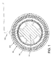
- FIG. 1 accelerometer 100 is positioned to sense motion of an object 124, which as illustrated is in the form of a stator winding 50 of a power generator or motor 52.
- Stator winding 50 is positioned about a rotor 54 of power generator or motor 52.
- FIGS. 2-3 show accelerometer 100 positioned to sense motion of an outer casing of stator winding 50, it is understood that it may alternatively be positioned to sense motion of a more interior stator winding.
- accelerometer 100 may include a pressure transducer 102, and a vibration-to-pressure converter (VPC) 104.
- Pressure transducer 102 may include any now known or later developed mechanism for converting a pressure to an electrical signal.
- VPC 104 includes a housing 106 and a diaphragm 110, forming a chamber 120 within housing 106.
- An area 122 between diaphragm 110 and object 124 is at least partially open to the environment, i.e., not enclosed.
- Housing 106 is mechanically coupled to object 124, e.g., by bolting, welding etc.
- housing 106 includes a single casing 108 that includes one or more vents 109 between diaphragm 110 and object 124.
- any structure capable of forming chamber 120 and mechanically coupling chamber 120 to object 124 such that vibrations are transmitted to housing 106 and diaphragm 110 may be employed.
- An upper end of housing 106 may be designed in a frusto-conical shape with an angle that will minimize the pressure wave reflection from the top of first chamber 120, e.g., an angle of 15° to 60° relative to horizontal, depending on the diameter of housing 106.
- Chamber 120 is fluidly coupled to pressure transducer 102 by, for example, a conduit 126.
- pressure transducer 102 may be located remotely, e.g., several meters, from housing 106.
- Diaphragm 110 may include a proof mass 130 coupled thereto in cases where diaphragm 110 does not include sufficient weight by itself to function.
- Diaphragm 110, proof mass 130 and fluid 140 may all be tuned to operate with pressure transducer 102.
- proof mass 130 is situated at the center of diaphragm 110 whose outer edge is fixed to an inside wall of housing 106. Other configurations are also possible.
- Object 124 may take a variety of forms.
- object 124 includes stator winding 50 of a power generator or a motor 52.
- FIGS. 2-3 show a more detailed cross-sectional view of stator winding 50 compared to FIG. 1 ).
- object 124 may include parts of an electrical transformer, a turbine, a hydro-power generator or practically any object the motion or vibration of which needs to be sensed.
- Fluid 140 within housing 106 can be any fluid, e.g., air, an inert gas, gelatins, etc., capable of transmitting pressure differentials sensed by diaphragm 110 to pressure transducer 102.
- accelerometer 100 allows for housing 106 and diaphragm 110 to be formed exclusively of non-metallic materials, e.g., high temperature plastic, high temperature ceramics, etc. Conduit 126 may also be formed at least partly of a non-metallic material. Such structure is advantageous because in some situation it is impossible to place metal containing accelerometers next to wires because they create interference with measurements. Pressure transducer 102 may be positioned remotely from object 124 so as to not interfere with the measurement. In addition, accelerometer 100 removes the presence of an electrical signal or circuit at the sensing location, which may also interfere with the measurement.
- non-metallic materials e.g., high temperature plastic, high temperature ceramics, etc.
- Conduit 126 may also be formed at least partly of a non-metallic material. Such structure is advantageous because in some situation it is impossible to place metal containing accelerometers next to wires because they create interference with measurements.
- Pressure transducer 102 may be positioned remotely from object 124 so as to not interfere with the measurement.
- accelerometer 100 can be applied in high electrical noise, high magnetic field and/or high electric field (high voltage) environments, e.g., of greater than 450V. Use of non-metallic materials also reduces costs.
- parts of accelerometer 100 such as housing 106 and conduit 126 may include high temperature metallic material (e.g., stainless steel, inconel, incoloy, etc.) and/or high temperature non-metallic materials (e.g., high temperature ceramics, high temperature plastics, etc.) for VPC 104 and conduit 126. Consequently, accelerometer 100 may be applied in high temperature environment, e.g., between 150-500 °C, such as a gas turbine casing, while pressure transducer 102 is remotely located from the high temperature environment.
- high temperature metallic material e.g., stainless steel, inconel, incoloy, etc.
- high temperature non-metallic materials e.g., high temperature ceramics, high temperature plastics, etc.
- FIG. 3 shows an alternative embodiment in which conduit 126 and VPC 104 include an acoustic dampening material 150 to protect the conduit from electrical noise or magnetic interference, which may impact a reading by pressure transducer 102, where pressure transducer 102 is remotely located from object 124.
- Acoustic dampening material 150 may include any now known or later developed vibration absorbing material.
- diaphragm 110 moves in response to acceleration forces created from object 124, which may act upon proof mass 130 supported by diaphragm 110. Since chamber 120 provides a closed system, filled with fluid, between VPC 104 and pressure transducer 102, movements of diaphragm 110 creates pressure waves that propagate through fluid 140 (via conduit 126) and are detected by pressure transducer 102. Hence, acceleration from object 124 is converted to a pressure signal, and eventually to an electrical signal by pressure transducer 102 remotely from object 124.
- conduit 126 is shown as including a bend, it is understood that conduit 126 may be any shape that allows for operative positioning of VPC 104 and pressure transducer 102.
- first,” “second,” and the like, herein do not denote any order, quantity, or importance, but rather are used to distinguish one element from another, and the terms “a” and “an” herein do not denote a limitation of quantity, but rather denote the presence of at least one of the referenced item.
- the modifier “about” used in connection with a quantity is inclusive of the stated value and has the meaning dictated by the context, (e.g., includes the degree of error associated with measurement of the particular quantity).
- suffix "(s)” as used herein is intended to include both the singular and the plural of the term that it modifies, thereby including one or more of that term (e.g., the metal(s) includes one or more metals).
Landscapes
- Physics & Mathematics (AREA)
- General Physics & Mathematics (AREA)
- Measuring Fluid Pressure (AREA)
- Measurement Of Mechanical Vibrations Or Ultrasonic Waves (AREA)
Abstract
Description
- The invention relates generally to accelerometers. More particularly, the invention relates to an accelerometer including a diaphragm.
- Accelerometers are devices that measure acceleration and gravity created reaction forces.
- A first aspect of the disclosure provides an accelerometer comprising: a pressure transducer; and a vibration-to-pressure converter (VPC) including: a housing mechanically coupled to an object to be measured, and a diaphragm sealing the housing to form a chamber, the chamber being fluidly coupled to the pressure transducer.
- A second aspect of the disclosure provides a power generator comprising: a rotor; a stator winding surrounding the rotor; and an accelerometer adjacent to the stator winding, the accelerometer including: a pressure transducer; and a vibration-to-pressure converter (VPC) including: a housing mechanically coupled to an object to be measured, and a diaphragm sealing the housing to form a chamber, the chamber being fluidly coupled to the pressure transducer.
- A third aspect of the disclosure provides a motor comprising: a rotor; a stator winding surrounding the rotor; and an accelerometer adjacent to the stator winding, the accelerometer including: a pressure transducer; and a vibration-to-pressure converter (VPC) including: a housing mechanically coupled to an object to be measured, and a diaphragm sealing the housing to form a chamber, the chamber being fluidly coupled to the pressure transducer.
- Various aspects and embodiments of the present invention will now be described in connection with the accompanying drawings, in which:
-
FIG. 1 is a cross-sectional view of a stator and rotor of a steam turbine. -
FIG. 2 is a cross-sectional view of an accelerometer according to an embodiment of the invention. -
FIG. 3 is a cross-sectional view of an accelerometer according to an embodiment of the invention. - The drawings show illustrative applications of an
accelerometer 100 according to various embodiments of the invention. In one setting, shown inFIG. 1 ,accelerometer 100 is positioned to sense motion of anobject 124, which as illustrated is in the form of a stator winding 50 of a power generator ormotor 52. Stator winding 50 is positioned about arotor 54 of power generator ormotor 52. AlthoughFIGS. 2-3 showaccelerometer 100 positioned to sense motion of an outer casing of stator winding 50, it is understood that it may alternatively be positioned to sense motion of a more interior stator winding. - Referring to the more detailed drawings in
FIGS. 2-3 ,accelerometer 100 may include apressure transducer 102, and a vibration-to-pressure converter (VPC) 104.Pressure transducer 102 may include any now known or later developed mechanism for converting a pressure to an electrical signal. VPC 104 includes ahousing 106 and adiaphragm 110, forming achamber 120 withinhousing 106. Anarea 122 betweendiaphragm 110 andobject 124 is at least partially open to the environment, i.e., not enclosed.Housing 106 is mechanically coupled toobject 124, e.g., by bolting, welding etc. In one embodiment,housing 106 includes asingle casing 108 that includes one ormore vents 109 betweendiaphragm 110 andobject 124. However, any structure capable of formingchamber 120 and mechanicallycoupling chamber 120 toobject 124 such that vibrations are transmitted tohousing 106 anddiaphragm 110 may be employed. An upper end ofhousing 106 may be designed in a frusto-conical shape with an angle that will minimize the pressure wave reflection from the top offirst chamber 120, e.g., an angle of 15° to 60° relative to horizontal, depending on the diameter ofhousing 106. -
Chamber 120 is fluidly coupled topressure transducer 102 by, for example, aconduit 126. In this manner,pressure transducer 102 may be located remotely, e.g., several meters, fromhousing 106.Diaphragm 110 may include aproof mass 130 coupled thereto in cases wherediaphragm 110 does not include sufficient weight by itself to function.Diaphragm 110,proof mass 130 andfluid 140 may all be tuned to operate withpressure transducer 102. As illustrated,proof mass 130 is situated at the center ofdiaphragm 110 whose outer edge is fixed to an inside wall ofhousing 106. Other configurations are also possible. -
Object 124 may take a variety of forms. In one example, shown inFIGS. 2-3 ,object 124 includes stator winding 50 of a power generator or amotor 52. (FIGS. 2-3 show a more detailed cross-sectional view of stator winding 50 compared toFIG. 1 ). In other examples,object 124 may include parts of an electrical transformer, a turbine, a hydro-power generator or practically any object the motion or vibration of which needs to be sensed. -
Fluid 140 withinhousing 106 can be any fluid, e.g., air, an inert gas, gelatins, etc., capable of transmitting pressure differentials sensed bydiaphragm 110 topressure transducer 102. - The structure of
accelerometer 100 allows forhousing 106 anddiaphragm 110 to be formed exclusively of non-metallic materials, e.g., high temperature plastic, high temperature ceramics, etc.Conduit 126 may also be formed at least partly of a non-metallic material. Such structure is advantageous because in some situation it is impossible to place metal containing accelerometers next to wires because they create interference with measurements.Pressure transducer 102 may be positioned remotely fromobject 124 so as to not interfere with the measurement. In addition,accelerometer 100 removes the presence of an electrical signal or circuit at the sensing location, which may also interfere with the measurement. Consequently,accelerometer 100 can be applied in high electrical noise, high magnetic field and/or high electric field (high voltage) environments, e.g., of greater than 450V. Use of non-metallic materials also reduces costs. Alternatively, parts ofaccelerometer 100 such ashousing 106 andconduit 126 may include high temperature metallic material (e.g., stainless steel, inconel, incoloy, etc.) and/or high temperature non-metallic materials (e.g., high temperature ceramics, high temperature plastics, etc.) for VPC 104 andconduit 126. Consequently,accelerometer 100 may be applied in high temperature environment, e.g., between 150-500 °C, such as a gas turbine casing, whilepressure transducer 102 is remotely located from the high temperature environment. -
FIG. 3 shows an alternative embodiment in whichconduit 126 and VPC 104 include anacoustic dampening material 150 to protect the conduit from electrical noise or magnetic interference, which may impact a reading bypressure transducer 102, wherepressure transducer 102 is remotely located fromobject 124.Acoustic dampening material 150 may include any now known or later developed vibration absorbing material. - In operation,
diaphragm 110 moves in response to acceleration forces created fromobject 124, which may act uponproof mass 130 supported bydiaphragm 110. Sincechamber 120 provides a closed system, filled with fluid, betweenVPC 104 andpressure transducer 102, movements ofdiaphragm 110 creates pressure waves that propagate through fluid 140 (via conduit 126) and are detected bypressure transducer 102. Hence, acceleration fromobject 124 is converted to a pressure signal, and eventually to an electrical signal bypressure transducer 102 remotely fromobject 124. Althoughconduit 126 is shown as including a bend, it is understood thatconduit 126 may be any shape that allows for operative positioning ofVPC 104 andpressure transducer 102. - The terms "first," "second," and the like, herein do not denote any order, quantity, or importance, but rather are used to distinguish one element from another, and the terms "a" and "an" herein do not denote a limitation of quantity, but rather denote the presence of at least one of the referenced item. The modifier "about" used in connection with a quantity is inclusive of the stated value and has the meaning dictated by the context, (e.g., includes the degree of error associated with measurement of the particular quantity). The suffix "(s)" as used herein is intended to include both the singular and the plural of the term that it modifies, thereby including one or more of that term (e.g., the metal(s) includes one or more metals).
- While various embodiments are described herein, it will be appreciated from the specification that various combinations of elements, variations or improvements therein may be made by those skilled in the art, and are within the scope of the invention. In addition, many modifications may be made to adapt a particular situation or material to the teachings of the invention without departing from essential scope thereof. Therefore, it is intended that the invention not be limited to the particular embodiment disclosed as the best mode contemplated for carrying out this invention, but that the invention will include all embodiments falling within the scope of the appended claims.
- Various aspects and embodiments of the present invention are defined by the following numbered clauses:
- 1. An accelerometer comprising:
- a pressure transducer; and
- a vibration-to-pressure converter (VPC) including:
- a housing mechanically coupled to an object to be measured, and
- a diaphragm sealing the housing to form a chamber, the chamber being fluidly coupled to the pressure transducer.
- 2. The accelerometer of clause 1, wherein the object includes a stator winding of a power generator or motor.
- 3. The accelerometer of any preceding clause, wherein the diaphragm includes a proof mass coupled thereto.
- 4. The accelerometer of any preceding clause, wherein the housing and the diaphragm are formed exclusively of non-metallic materials.
- 5. The accelerometer of any preceding clause, wherein the chamber is fluidly coupled to the pressure transducer by a conduit.
- 6. The accelerometer of any preceding clause, further comprising an acoustic dampening material protecting the conduit and the VPC from external noise.
- 7. A power generator comprising:
- a rotor;
- a stator winding surrounding the rotor; and
- an accelerometer adjacent to the stator winding, the accelerometer including:
- a pressure transducer; and
- a vibration-to-pressure converter (VPC) including:
- a housing mechanically coupled to an object to be measured, and
- a diaphragm sealing the housing to form a chamber, the chamber being fluidly coupled to the pressure transducer.
- 8. The power generator of clause 7, wherein the diaphragm includes a proof mass coupled thereto.
- 9. The power generator of clause 7 or 8, wherein the housing and the diaphragm are formed exclusively of non-metallic materials.
- 10. The power generator of any of clauses 7 to 9, wherein the chamber is fluidly coupled to the pressure transducer by a conduit.
- 11. The power generator of any of clauses 7 to 10, further comprising an acoustic dampening material protecting the conduit and the VPC from external noise.
- 12. A motor comprising:
- a rotor;
- a stator winding surrounding the rotor; and
- an accelerometer adjacent to the stator winding, the accelerometer including:
- a pressure transducer; and
- a vibration-to-pressure converter (VPC) including:
- a housing mechanically coupled to an object to be measured, and
- a diaphragm sealing the housing to form a chamber, the chamber being fluidly coupled to the pressure transducer.
- 13. The motor of clause 12, wherein the diaphragm includes a proof mass coupled thereto.
- 14. The motor of clause 12 or 13, wherein the housing and the diaphragm are formed exclusively of non-metallic materials.
- 15. The motor of any of clauses 12 to 14, wherein the chamber is fluidly coupled to the pressure transducer by a conduit.
- 16. The motor of any of clauses 12 to 15, further comprising an acoustic dampening material protecting the conduit and the VPC from external noise.
Claims (10)
- An accelerometer (100) comprising:a pressure transducer (102); anda vibration-to-pressure converter (VPC) (104) including:a housing (106) mechanically coupled to an object (24) to be measured, anda diaphragm (110) sealing the housing (106) to form a chamber (120), the chamber (120) being fluidly coupled to the pressure transducer (102).
- The accelerometer (100) of claim 1, wherein the object (24) includes a stator winding (50) of a power generator or motor (52).
- The accelerometer (100) of any preceding claim, wherein the diaphragm (110) includes a proof mass (130) coupled thereto.
- The accelerometer (100) of any preceding claim, wherein the housing (106) and the diaphragm (110) are formed exclusively of non-metallic materials.
- The accelerometer (100) of any preceding claim, wherein the chamber (120) is fluidly coupled to the pressure transducer (102) by a conduit (126).
- The accelerometer (100) of claim 5, further comprising an acoustic dampening material (150) protecting the conduit (126) and the VPC (104) from external noise.
- A power generator comprising:a rotor (54);a stator winding (50) surrounding the rotor (54); andan accelerometer (100) adjacent to the stator winding (50), the accelerometer (100) including:a pressure transducer (102); anda vibration-to-pressure converter (VPC) (104) including:a housing (106) mechanically coupled to an object (24) to be measured, anda diaphragm (110) sealing the housing (106) to form a chamber (120), the chamber (120) being fluidly coupled to the pressure transducer (102).
- The power generator of claim 7, wherein the diaphragm (110) includes a proof mass (130) coupled thereto.
- The power generator of claim 7 or claim 8, wherein the chamber (120) is fluidly (140) coupled to the pressure transducer (102) by a conduit (126).
- A motor (52) comprising:a rotor (54);a stator winding (50) surrounding the rotor (54); andan accelerometer (100) adjacent to the stator winding (50), the accelerometer (100) including:a pressure transducer (102); anda vibration-to-pressure converter (VPC) (104) including:a housing (106) mechanically coupled to an object (24) to be measured, anda diaphragm (110) sealing the housing (106) to form a chamber (120), the chamber (120) being fluidly coupled to the pressure transducer (102).
Applications Claiming Priority (1)
| Application Number | Priority Date | Filing Date | Title |
|---|---|---|---|
| US12/240,316 US7874215B2 (en) | 2008-09-29 | 2008-09-29 | Accelerometer including diaphragm and power generator and motor including same |
Publications (1)
| Publication Number | Publication Date |
|---|---|
| EP2169365A1 true EP2169365A1 (en) | 2010-03-31 |
Family
ID=41560883
Family Applications (1)
| Application Number | Title | Priority Date | Filing Date |
|---|---|---|---|
| EP09170410A Withdrawn EP2169365A1 (en) | 2008-09-29 | 2009-09-16 | Accelerometer including diaphragm and power generator and motor including same |
Country Status (4)
| Country | Link |
|---|---|
| US (1) | US7874215B2 (en) |
| EP (1) | EP2169365A1 (en) |
| JP (1) | JP5537877B2 (en) |
| CN (1) | CN101713786A (en) |
Families Citing this family (2)
| Publication number | Priority date | Publication date | Assignee | Title |
|---|---|---|---|---|
| US7974215B1 (en) * | 2008-02-04 | 2011-07-05 | Crossroads Systems, Inc. | System and method of network diagnosis |
| US9932852B2 (en) | 2011-08-08 | 2018-04-03 | General Electric Company | Sensor assembly for rotating devices and methods for fabricating |
Citations (6)
| Publication number | Priority date | Publication date | Assignee | Title |
|---|---|---|---|---|
| US2702883A (en) | 1951-05-12 | 1955-02-22 | Stewart Warner Corp | Vibration pickup |
| GB2104658A (en) * | 1981-08-26 | 1983-03-09 | Hitachi Ltd | Detecting rubbing in rotary machines |
| JPH01156669A (en) | 1987-12-15 | 1989-06-20 | Fujikura Ltd | Acceleration sensor |
| GB2282891A (en) | 1993-10-13 | 1995-04-19 | Tokai Rika Co Ltd | Accelerometer |
| US5831165A (en) | 1994-05-27 | 1998-11-03 | Kabushiki Kaisha Tokai Rika Denki Seisakusho | Acceleration sensor |
| US20040216525A1 (en) * | 2002-07-19 | 2004-11-04 | Hitachi, Ltd. | Measurement system of torsion vibration for reactor internal pump |
Family Cites Families (5)
| Publication number | Priority date | Publication date | Assignee | Title |
|---|---|---|---|---|
| US6608419B2 (en) * | 2000-12-27 | 2003-08-19 | General Electric Company | Flux shunt for a power generator stator assembly |
| KR20050111662A (en) * | 2004-05-21 | 2005-11-28 | 삼성전자주식회사 | Pressure and vibration sensor |
| JP4869249B2 (en) * | 2005-11-16 | 2012-02-08 | 株式会社東芝 | Stator core looseness diagnosis device and stator core looseness diagnosis method |
| US7348707B2 (en) * | 2005-11-30 | 2008-03-25 | General Electric Company | Electromechanical device having three-dimensional stator laminations |
| CN2901271Y (en) * | 2006-06-14 | 2007-05-16 | 中国石油天然气集团公司 | Flange diaphragm sealed liquid level and pressure transmitter |
-
2008
- 2008-09-29 US US12/240,316 patent/US7874215B2/en active Active
-
2009
- 2009-09-16 EP EP09170410A patent/EP2169365A1/en not_active Withdrawn
- 2009-09-18 JP JP2009216352A patent/JP5537877B2/en not_active Expired - Fee Related
- 2009-09-28 CN CN200910179545A patent/CN101713786A/en active Pending
Patent Citations (6)
| Publication number | Priority date | Publication date | Assignee | Title |
|---|---|---|---|---|
| US2702883A (en) | 1951-05-12 | 1955-02-22 | Stewart Warner Corp | Vibration pickup |
| GB2104658A (en) * | 1981-08-26 | 1983-03-09 | Hitachi Ltd | Detecting rubbing in rotary machines |
| JPH01156669A (en) | 1987-12-15 | 1989-06-20 | Fujikura Ltd | Acceleration sensor |
| GB2282891A (en) | 1993-10-13 | 1995-04-19 | Tokai Rika Co Ltd | Accelerometer |
| US5831165A (en) | 1994-05-27 | 1998-11-03 | Kabushiki Kaisha Tokai Rika Denki Seisakusho | Acceleration sensor |
| US20040216525A1 (en) * | 2002-07-19 | 2004-11-04 | Hitachi, Ltd. | Measurement system of torsion vibration for reactor internal pump |
Also Published As
| Publication number | Publication date |
|---|---|
| CN101713786A (en) | 2010-05-26 |
| US7874215B2 (en) | 2011-01-25 |
| JP5537877B2 (en) | 2014-07-02 |
| JP2010085400A (en) | 2010-04-15 |
| US20100079017A1 (en) | 2010-04-01 |
Similar Documents
| Publication | Publication Date | Title |
|---|---|---|
| EP3267207B1 (en) | Speed or torque probe for gas turbine engines | |
| CN102203686B (en) | Industrial process power scavenging device and method of deriving process device power from an industrial process | |
| JP6634525B2 (en) | Sensor assembly for sensor, and sensor and measurement system formed with the same | |
| JP6552867B2 (en) | Passive wireless sensor | |
| CN210464558U (en) | a sensor | |
| US10287854B2 (en) | Vortex energy harvester for downhole applications | |
| EP2689164B1 (en) | Gear with vibration sensor | |
| US7874215B2 (en) | Accelerometer including diaphragm and power generator and motor including same | |
| JP2004532986A (en) | Flexible dynamic housing | |
| US20090323075A1 (en) | Flexural disc fiber optic sensor | |
| GB2530565A (en) | Acoustic thermometry | |
| EP0144937B1 (en) | Vortex flow meter | |
| CN114830201B (en) | Measurement system and diagnostic system | |
| CN102809389B (en) | instrumentation rake assembly | |
| JP7331821B2 (en) | field equipment | |
| EP0509416B1 (en) | Sensor supporting structure for an accelerometer | |
| JP6637518B2 (en) | Integrated mechanical and electric motor | |
| RU2296953C2 (en) | Gas flow meter with transformation of stream oscillation to electronic signal | |
| CN113720250A (en) | Adiabatic magnetostrictive sensor | |
| JP2005315806A (en) | Vibration measuring device | |
| JP2007286013A (en) | Pressure sensor with disturbance compensation function | |
| CN119164278A (en) | Inductive Linear Position Detection Sensors | |
| CN114322735A (en) | High-sensitivity sheet-shaped piezoresistive magnetostrictive transducer based on MEMS technology | |
| Gibert et al. | Flow induced vibrations of secondary piping of LMFBR |
Legal Events
| Date | Code | Title | Description |
|---|---|---|---|
| PUAI | Public reference made under article 153(3) epc to a published international application that has entered the european phase |
Free format text: ORIGINAL CODE: 0009012 |
|
| AK | Designated contracting states |
Kind code of ref document: A1 Designated state(s): AT BE BG CH CY CZ DE DK EE ES FI FR GB GR HR HU IE IS IT LI LT LU LV MC MK MT NL NO PL PT RO SE SI SK SM TR |
|
| AX | Request for extension of the european patent |
Extension state: AL BA RS |
|
| 17P | Request for examination filed |
Effective date: 20100930 |
|
| 17Q | First examination report despatched |
Effective date: 20101027 |
|
| GRAP | Despatch of communication of intention to grant a patent |
Free format text: ORIGINAL CODE: EPIDOSNIGR1 |
|
| INTG | Intention to grant announced |
Effective date: 20150330 |
|
| STAA | Information on the status of an ep patent application or granted ep patent |
Free format text: STATUS: THE APPLICATION IS DEEMED TO BE WITHDRAWN |
|
| 18D | Application deemed to be withdrawn |
Effective date: 20150811 |