EP2169358A2 - Displacement measurement apparatus - Google Patents
Displacement measurement apparatus Download PDFInfo
- Publication number
- EP2169358A2 EP2169358A2 EP09170356A EP09170356A EP2169358A2 EP 2169358 A2 EP2169358 A2 EP 2169358A2 EP 09170356 A EP09170356 A EP 09170356A EP 09170356 A EP09170356 A EP 09170356A EP 2169358 A2 EP2169358 A2 EP 2169358A2
- Authority
- EP
- European Patent Office
- Prior art keywords
- diffracted
- diffraction grating
- photodetector
- gto
- diffracted beam
- Prior art date
- Legal status (The legal status is an assumption and is not a legal conclusion. Google has not performed a legal analysis and makes no representation as to the accuracy of the status listed.)
- Withdrawn
Links
- 238000006073 displacement reaction Methods 0.000 title claims abstract description 158
- 238000005259 measurement Methods 0.000 title claims abstract description 98
- 230000003287 optical effect Effects 0.000 claims description 53
- 101100257798 Arabidopsis thaliana GBSS1 gene Proteins 0.000 claims description 6
- 238000005286 illumination Methods 0.000 claims description 4
- 230000005540 biological transmission Effects 0.000 claims description 2
- 230000000737 periodic effect Effects 0.000 description 22
- 239000013307 optical fiber Substances 0.000 description 5
- NCGICGYLBXGBGN-UHFFFAOYSA-N 3-morpholin-4-yl-1-oxa-3-azonia-2-azanidacyclopent-3-en-5-imine;hydrochloride Chemical compound Cl.[N-]1OC(=N)C=[N+]1N1CCOCC1 NCGICGYLBXGBGN-UHFFFAOYSA-N 0.000 description 4
- 230000000694 effects Effects 0.000 description 3
- 239000000758 substrate Substances 0.000 description 3
- 238000001514 detection method Methods 0.000 description 2
- 238000000034 method Methods 0.000 description 2
- 239000011295 pitch Substances 0.000 description 2
- 230000010287 polarization Effects 0.000 description 2
- 239000004065 semiconductor Substances 0.000 description 2
- VYPSYNLAJGMNEJ-UHFFFAOYSA-N Silicium dioxide Chemical compound O=[Si]=O VYPSYNLAJGMNEJ-UHFFFAOYSA-N 0.000 description 1
- 230000002411 adverse Effects 0.000 description 1
- 238000006243 chemical reaction Methods 0.000 description 1
- 239000002131 composite material Substances 0.000 description 1
- 238000009826 distribution Methods 0.000 description 1
- 238000005530 etching Methods 0.000 description 1
- 238000003754 machining Methods 0.000 description 1
- 238000004519 manufacturing process Methods 0.000 description 1
- 238000000926 separation method Methods 0.000 description 1
- 239000007787 solid Substances 0.000 description 1
Images






Classifications
-
- G—PHYSICS
- G01—MEASURING; TESTING
- G01B—MEASURING LENGTH, THICKNESS OR SIMILAR LINEAR DIMENSIONS; MEASURING ANGLES; MEASURING AREAS; MEASURING IRREGULARITIES OF SURFACES OR CONTOURS
- G01B9/00—Measuring instruments characterised by the use of optical techniques
- G01B9/02—Interferometers
-
- G—PHYSICS
- G01—MEASURING; TESTING
- G01D—MEASURING NOT SPECIALLY ADAPTED FOR A SPECIFIC VARIABLE; ARRANGEMENTS FOR MEASURING TWO OR MORE VARIABLES NOT COVERED IN A SINGLE OTHER SUBCLASS; TARIFF METERING APPARATUS; MEASURING OR TESTING NOT OTHERWISE PROVIDED FOR
- G01D5/00—Mechanical means for transferring the output of a sensing member; Means for converting the output of a sensing member to another variable where the form or nature of the sensing member does not constrain the means for converting; Transducers not specially adapted for a specific variable
- G01D5/26—Mechanical means for transferring the output of a sensing member; Means for converting the output of a sensing member to another variable where the form or nature of the sensing member does not constrain the means for converting; Transducers not specially adapted for a specific variable characterised by optical transfer means, i.e. using infrared, visible, or ultraviolet light
- G01D5/32—Mechanical means for transferring the output of a sensing member; Means for converting the output of a sensing member to another variable where the form or nature of the sensing member does not constrain the means for converting; Transducers not specially adapted for a specific variable characterised by optical transfer means, i.e. using infrared, visible, or ultraviolet light with attenuation or whole or partial obturation of beams of light
- G01D5/34—Mechanical means for transferring the output of a sensing member; Means for converting the output of a sensing member to another variable where the form or nature of the sensing member does not constrain the means for converting; Transducers not specially adapted for a specific variable characterised by optical transfer means, i.e. using infrared, visible, or ultraviolet light with attenuation or whole or partial obturation of beams of light the beams of light being detected by photocells
- G01D5/36—Forming the light into pulses
- G01D5/38—Forming the light into pulses by diffraction gratings
-
- G—PHYSICS
- G01—MEASURING; TESTING
- G01B—MEASURING LENGTH, THICKNESS OR SIMILAR LINEAR DIMENSIONS; MEASURING ANGLES; MEASURING AREAS; MEASURING IRREGULARITIES OF SURFACES OR CONTOURS
- G01B11/00—Measuring arrangements characterised by the use of optical techniques
Definitions
- the present invention relates to measurement apparatuses that obtain displacement information by converting relative displacements of objects into periodic signals and counting the periodic signals, and also relates to multi-axial displacement measurement apparatuses that measure displacements in multiple directions.
- a displacement measurement apparatus that measures relative displacement of a mechanical stage employ optical encoders and laser interferometers.
- FIG. 4 An exemplary displacement measurement apparatus that measures displacement along a single axis is disclosed in Japanese Patent Laid-Open No. 6-18291 (see Fig. 4 therein).
- This apparatus is an interference encoder, and causes a 0th-order diffracted light beam and a +1st-order diffracted light beam resulting from light transmitted through a diffraction grating to be incident on another diffraction grating provided on a scale attached to an object to be measured, whereby a +1st-order reflected diffracted light beam resulting from the 0th-order diffracted light beam and a -1st-order reflected diffracted light beam resulting from the +1st-order diffracted light beam interfere with each other.
- the intensity of interference light varies with the amount of displacement. Therefore, displacement of the object is measured by detecting the intensity of interference light with a photodetector.
- FIG. 1 Another displacement measurement apparatus is disclosed in Japanese Patent Laid-Open No. 2007-171206 (see Figs. 1 and 19 therein).
- This apparatus measures displacement in one direction (along the X axis) within a plane in which a diffraction grating that moves together with an object to be measured is provided, and displacement in another direction (along the Z axis) orthogonal to the plane.
- the displacements in the X and Z directions are measured with respective measurement systems, each including a light source, an interferometer core, a polarization conversion device, a detector, and so forth.
- two measurement systems are provided in parallel, and two light beams are applied, at Littrow angles, to a diffraction grating, whereby reflected diffracted light beams are produced.
- two pieces of displacement information as composite information with respect to the X and Z directions i.e., Z+X information and Z-X information, are obtained.
- Z+X information and Z-X information are obtained.
- Japanese Patent Laid-Open No. 2007-171206 also discloses a triaxial displacement measurement apparatus that measures displacements in two directions (along the X and Y axes) within a plane in which a diffraction grating that moves together with an object to be measured is provided, and displacement in another direction (along the Z axis) orthogonal to the plane. Also in this case, the same measurement principle as in the biaxial measurement along the X and Z axes applies. That is, three measurement systems are used so as to obtain three pieces of displacement information, i.e., Z+X information, Z-X information, and Z+Y information. Thus, X-direction displacement information, Y-direction displacement information, and Z-direction displacement information are calculated.
- FIG. 1 Another displacement measurement apparatus that measures displacements in two directions within a plane in which a diffraction grating that moves together with an object to be measured is provided is disclosed in Japanese Patent Laid-Open No. 6-288722 (see Fig. 1 therein).
- This apparatus measures displacements of the object in two directions (along the X and Y axes) that are orthogonal to each other within the plane.
- a diffraction grating having a checkerboard pattern and configured to move together with the object is provided in a plane containing the X and Y axes. Light is made to be orthogonally incident on the diffraction grating.
- the displacement measurement apparatus disclosed in Japanese Patent Laid-Open No. 2007-171206 requires a plurality of measurement systems, each including a light source, a polarization beam splitter, a deflector, a photodetector, and so forth, so as to measure displacement in a direction defined within the plane where the diffraction grating is provided and displacement in a direction orthogonal to the plane. Therefore, the apparatus becomes larger and more complicated. Moreover, in the case where a plurality of measurement systems are provided, since positions where measurements are performed vary with different axes, errors may occur particularly when high measurement accuracy is required. In addition, mathematical operations performed by a field-programmable gate array (FPGA), a central processing unit (CPU), or the like include separation operation, preventing quick signal output. For these reasons, such an apparatus may be impractical for use in stage control.
- FPGA field-programmable gate array
- CPU central processing unit
- the displacement measurement apparatus disclosed in Japanese Patent Laid-Open No. 6-288722 measures displacements in two directions within the plane where the diffraction grating is provided, by introducing the plurality of diffracted light beams, produced by light transmitted through the diffraction grating, into the strip waveguides provided in a plane parallel to the diffraction grating.
- the diffraction grating configured to move together with the object is a transmissive component, and therefore is provided between the light source and the incidence diffraction gratings. This increases the size and complexity of the apparatus.
- the present invention provides a displacement measurement apparatus capable of measuring, with a single measurement system, displacement in a direction defined within a plane where a diffraction grating is provided and displacement in a direction perpendicular to the plane, by utilizing a plurality of diffracted light beams that are produced from light emitted from a light source and diffracted through the diffraction grating.
- the present invention also provides a displacement measurement apparatus having a simple and compact configuration and capable of measuring displacements in two directions defined within a plane where a diffraction grating is provided.
- the present invention in its first aspect provides a displacement measurement apparatus as specified in claims 1 to 11.
- the present invention in its second aspect provides an exposure apparatus as specified in claim 12.
- displacements in different directions are obtained as periodic signals that are independent from each other but are generated simultaneously. Therefore, the time required for calculation by a CPU or an FPGA can be reduced. Furthermore, compared with an apparatus including a plurality of measurement systems, the displacement measurement apparatus according to the above aspect of the present invention, including a single measurement system, is constituted by a smaller number of optical components that are substantially common to measurements in different directions. Therefore, the size of the apparatus can be reduced. Moreover, since detections for different directions are performed at a substantially single position, errors due to inclination and the like can be largely reduced.
- Fig. 1 is a schematic perspective view showing optical elements of a displacement measurement apparatus according to a first exemplary embodiment of the present invention.
- Fig. 2 is a schematic cross-sectional view showing the optical elements of the displacement measurement apparatus according to the first exemplary embodiment.
- Fig. 3 illustrates diffraction and light-splitting functions of a first diffraction grating GBSO.
- Fig. 4 includes schematic perspective views showing variations of the first diffraction grating GBSO and a second diffraction grating GTO.
- Fig. 5 illustrates diffraction and light-splitting functions of the second diffraction grating GTO.
- Fig. 6 illustrates two light beams incident on a photodetector and interference fringes produced by the two light beams on photodetector elements.
- Fig. 7 is a schematic cross-sectional view showing optical elements of a displacement measurement apparatus according to a second exemplary embodiment of the present invention.
- Fig. 8 is a schematic perspective view showing optical elements of a displacement measurement apparatus according to a third exemplary embodiment of the present invention.
- Fig. 9 is a schematic perspective view showing optical elements of a displacement measurement apparatus according to a fourth exemplary embodiment of the present invention.
- Fig. 10 is a schematic cross-sectional view showing the optical elements of the displacement measurement apparatus according to the fourth exemplary embodiment.
- Fig. 11 is a schematic cross-sectional view showing optical elements of a displacement measurement apparatus according to a fifth exemplary embodiment of the present invention.
- Fig. 12 is a schematic perspective view showing optical elements of a displacement measurement apparatus according to a sixth exemplary embodiment of the present invention.
- Fig. 13 is a schematic perspective view showing optical elements of a displacement measurement apparatus according to a seventh exemplary embodiment of the present invention.
- Fig. 14 shows an arrangement of an optical system included in an exemplary displacement measurement apparatus that measures displacements by utilizing diffracted light beams in eight directions.
- Fig. 15 schematically shows an exemplary exposure apparatus including any of the displacement measurement apparatuses according to the exemplary embodiments.
- a displacement measurement apparatus includes a first diffraction grating, a second diffraction grating, a first photodetector, a second photodetector, and a calculation unit.
- the first diffraction grating transmits light emitted from a light source, and produces a plurality of diffracted light beams, including first, second, and third diffracted beams, to be output in different directions.
- the first, second, and third diffracted beams further undergo diffraction, reflection, and the like, thereby producing interference light.
- displacements in a plurality of directions can be measured. That is, a single measurement system measures displacements in a plurality of directions.
- the second diffraction grating is provided in a plane parallel to the first diffraction grating, and is movable together with an object to be measured.
- the second diffraction grating reflects the first, second, and third diffracted beams produced by the first diffraction grating.
- the first photodetector receives the first and second diffracted beams that are diffracted by the second diffraction grating.
- the second photodetector receives at least the third diffracted beam.
- the first and second photodetectors are provided for measuring displacements of the object in respective directions.
- the beams received by each of the photodetectors represent displacement in one direction. This means that there is no need to calculate displacement in one direction in accordance with beams received by a plurality of photodetectors. Accordingly, real-time control of the object in a plurality of directions is realized.
- the calculation unit calculates displacement of the object in a first direction in accordance with the beams received by the first photodetector, and displacement of the object in a second direction, different from the first direction, in accordance with the beams received by the second photodetector. Since the beams received by each of the photodetectors represent displacement in one direction, the calculation unit may include two separate units: a unit responsible for calculation of displacement in the first direction, and a unit responsible for calculation of displacement in the second direction.
- Fig. 1 is a schematic perspective view showing optical elements of a displacement measurement apparatus according to a first exemplary embodiment of the present invention.
- Fig. 2 is a schematic cross-sectional view showing the optical elements of the displacement measurement apparatus according to the first exemplary embodiment.
- Figs. 1 and 2 each show a first diffraction grating GBSO, a second diffraction grating GTO, a first photodetector PDy, a second photodetector PDz, calculation units CU, a reflector FM, a lens LNS, and a light source LS.
- the X axis and the Y axis lie in a plane where the first and second diffraction gratings GBSO and GTO are provided, and the Z axis is perpendicular to the plane.
- displacement in the Y direction and displacement in the Z direction are to be measured.
- the Y direction corresponds to the first direction
- the Z direction corresponds to the second direction.
- the first diffraction grating GBSO is provided in a plane containing the X and Y axes, and has a grating pattern of fine structures periodically arranged in the X and Y directions.
- the lens LNS is positioned relative to the first diffraction grating GBSO in the Z direction, and the light source LS is positioned farther from the first diffraction grating GBSO than the lens LNS.
- the fine periodic grating pattern of the first diffraction grating GBSO is provided on a surface thereof remote from the lens LNS and the light source LS.
- the first diffraction grating GBSO produces a plurality of light beams from a single light beam.
- the first diffraction grating GBSO is provided as a substrate having a micron-order pattern in which two-dimensional fine figures are arranged or three-dimensional fine structures are two-dimensionally arranged.
- a diffractive optical element having such a pattern of fine figures/structures can be prepared by processing a quartz-glass substrate by photolithographic selective etching, a replica method, or the like.
- the second diffraction grating GTO is provided on a side opposite the lens LNS and the light source LS with respect to the first diffraction grating GBSO so as to be parallel to the first diffraction grating GBSO, and has on a surface thereof facing the first diffraction grating GBSO fine periodic structures arranged in a grating pattern at least in the Y direction.
- the second diffraction grating GTO moves together with the object to be measured. Therefore, by measuring the displacement of the second diffraction grating GTO, displacement of the object can be measured.
- the second diffraction grating GTO reflects and diffracts light.
- the second diffraction grating GTO also splits a single light beam into a plurality of light beams, as does the first diffraction grating GBSO, and is provided as a substrate having a micron-order pattern in which two-dimensional fine figures are arranged or three-dimensional fine structures are two-dimensionally arranged, such as those shown in Fig. 4 .
- the pattern can be formed by the same method as for the pattern of the first diffraction grating GBSO.
- the diffracted light beams shown in Figs. 3 and 5 are representative beams, and in general there are other beams produced in the outside area of the shown beams.
- the distribution of the amount of light of such beams is changeable by appropriately changing the designs, including the shape of the fine figures/structures, the ratio of the gap between the figures/structures, the amount of level difference, and the like. That is, the designs can be optimized to efficiently produce necessary light beams. Fig.
- FIG. 4 shows variations of the fine pattern, including a pattern of transmissive and nontransmissive fine figures, a pattern of fine two-tiered structures, a pattern of structures with a changed amount of level difference, a pattern of structures with a changed ratio of the gap between structures, a pattern of structures in a changed arrangement, and a pattern of fine three-tiered solid structures.
- the first photodetector PDy and the second photodetector PDz of the first exemplary embodiment are provided in the plane where the first diffraction grating GBSO is provided, and receive the light diffracted by being transmitted through the first diffraction grating GBSO and then reflected by the second diffraction grating GTO.
- the first photodetector PDy measures displacement of the object in the Y direction.
- the second photodetector PDz measures displacement of the object in the Z direction.
- the first and second photodetectors PDy and PDz can be configured in various ways, as long as they can measure changes in interference fringes produced by interference between a plurality of light beams.
- the first and second photodetectors PDy and PDz each include four comb-shaped photodetector elements A(+), A(-), B(+), and B(-) having identical shapes.
- the four comb-shaped photodetector elements are staggered with respect to each other by 1/4 of the pitch of teeth thereof.
- the width of each tooth corresponds to 1/4 or smaller of the tooth period. Thus, light falls onto all the teeth of the four elements.
- first photodetector PDy when the second diffraction grating GTO moves relative thereto in the Y direction, sine-wave periodic signals that are out of phase with each other by 1/4 period are output from the four photodetector elements, respectively. In accordance with these signals, displacement in the Y direction can be measured.
- second photodetector PDz when the second diffraction grating GTO moves relative thereto in the Z direction, sine-wave periodic signals that are out of phase with each other by 1/4 period are output from the four photodetector elements, respectively. In accordance with these signals, displacement in the Z direction can be measured.
- the photodetectors PDy and PDz according to the first exemplary embodiment of the present invention may each include only two or three, instead of four, comb-shaped photodetector elements, as long as a plurality of signals that are out of phase with each other can be obtained.
- the photodetectors PDy and PDz may be each constituted by plate-like elements having slits, instead of comb-shaped elements.
- Photodetectors constituted by comb-shaped elements are advantageous in that they cause little loss of light, leading to improvement in measurement accuracy, and are therefore suitable for use in controlling, for example, stages of exposure apparatuses, in which highly accurate measurement is required.
- photodetectors constituted by plate-like elements having slits are advantageous in that the assembly cost can be reduced.
- the calculation units CU calculate displacements of the object in the different directions in accordance with the signals output from the first and second photodetectors PDy and PDz.
- the calculation units CU may be provided at any position in the displacement measurement apparatus.
- a unit that calculates displacement in the Y direction is provided integrally with the first photodetector PDy
- a unit that calculates displacement in the Z direction is provided integrally with the second photodetector PDz.
- the reflector FM is provided between the first diffraction grating GBSO and the second diffraction grating GT0, specifically, at the midpoint between the two.
- the reflector FM has on both sides thereof reflective surfaces so as to reflect both of the light from the first diffraction grating GBSO and the light from the second diffraction grating GTO, the reflective surfaces extending parallel to the first and second diffraction gratings GBSO and GTO.
- the light source LS is provided such that the light therefrom is to be incident on the first diffraction grating GBSO through the lens LNS.
- the light source LS may be any of the following, in accordance with optical conditions: a laser diode (LD), a vertical-cavity surface-emitting laser (VCSEL), a superluminescent diode (SLD), and the like.
- a laser diode LD
- VCSEL vertical-cavity surface-emitting laser
- SLD superluminescent diode
- an LD is employed as the light source LS.
- the lens LNS is provided between the light source LS and the first diffraction grating GBSO, under such optical conditions that light emitted from the light source LS is incident as parallel light on the first diffraction grating GBSO.
- the light source LS and the lens LNS may be provided either inside or outside the displacement measurement apparatus.
- the displacement measurement apparatus includes the light source LS and the lens LNS.
- Divergent light beams emitted from the light source LS are converted into parallel light beams by the lens LNS and are incident on the first diffraction grating GBSO.
- the beams incident on the first diffraction grating GBSO is transmitted therethrough and produce a plurality of diffracted beams, including a first diffracted beam l 1 , a second diffracted beam l 2 , and a third diffracted beam l 3 , that are output in directions different from each other.
- the first diffracted beam l 1 is transmitted through the first diffraction grating GBSO and travels straight ahead, producing a 0th-order diffracted beam; the second diffracted beam l 2 is diffracted in the +Y direction, producing a 1st-order diffracted beam; and the third diffracted beam l 3 is diffracted in the -Y direction, producing a -1st-order diffracted beam.
- the first diffracted beam l 1 produced by the first diffraction grating GBSO travels straight ahead and is incident at point P 1 on the second diffraction grating GTO provided on a relative movement scale that moves together with the object to be measured.
- the second diffracted beam l 2 is diffracted and deflected by the first diffraction grating GBSO and is incident at point P 2 on the second diffraction grating GTO.
- the third diffracted beam l 3 is diffracted and deflected by the first diffraction grating GBSO and is incident at point P 3 on a surface of the reflector FM facing the first diffraction grating GBSO.
- the first diffracted beam l 1 incident at point P 1 is reflected by the second diffraction grating GTO and produces a +1st-order diffracted beam that is diffracted in the +Y direction and a -1st-order diffracted beam that is diffracted in the -Y direction.
- the +1st-order diffracted beam is obliquely incident on the first photodetector PDy.
- the second diffracted beam l 2 incident at point P 2 undergoes -1st-order diffraction and is perpendicularly incident on the first photodetector PDy.
- the two beams incident on the first photodetector PDy interfere with each other, producing interference fringes thereon.
- the interference fringes also move.
- sine-wave signals are output from the first photodetector PDy.
- the phases of the signals are calculated by the corresponding calculation unit CU.
- the period, height, and the like of the periodic pattern on each of the first and second diffraction gratings GBSO and GTO are set such that the period of the interference fringes produced as above becomes the same as the tooth period of the first photodetector PDy.
- the period of the interference fringes produced as described above is also the same as the foregoing two.
- the Y-direction period of the periodic pattern on the first diffraction grating GBSO, the Y-direction period of the periodic pattern on the second diffraction grating GTO, and the tooth period of the first photodetector PDy are set to be the same as each other.
- the third diffracted beam l 3 incident at point P 3 on the surface of the reflector FM facing the first diffraction grating GBSO is reflected by the reflector FM and is obliquely incident on the second photodetector PDz.
- the first diffracted beam l 1 incident at point P 1 is reflected by the second diffraction grating GTO and produces the +1st-order diffracted beam that is diffracted in the +Y direction and the -1st-order diffracted beam that is diffracted in the -Y direction.
- the -1st-order diffracted beam is incident at point P 4 on the surface of the reflector FM facing the second diffraction grating GTO and is reflected by the reflector FM.
- the first diffracted beam l 1 reflected at point P 4 is then incident at point P 5 on the second diffraction grating GTO, and produces a +1st-order diffracted beam.
- the +1st-order diffracted beam is then output in the -Z direction and is perpendicularly incident on the second photodetector PDz.
- the two beams incident on the second photodetector PDz interfere with each other, producing interference fringes thereon.
- the interference fringes also move.
- sine-wave signals are output from the second photodetector PDz.
- the phases of the signals are calculated by the corresponding calculation unit CU.
- the period, height, and the like of the periodic pattern on each of the first and second diffraction gratings GBSO and GTO are set such that the period of the interference fringes produced as above becomes the same as the tooth period of the second photodetector PDz.
- the beams diffracted in the Y direction are utilized for measurement of displacement in the Z direction. Therefore, the Y-direction period of the periodic pattern on each of the first and second diffraction gratings GBSO and GTO and the tooth period of the second photodetector PDz are set to be the same as each other.
- ⁇ d 2 ⁇ 1 cos sin - 1 ⁇ / P y + 1 ⁇ ⁇ ⁇ z
- ⁇ denotes the center wavelength of light from the light source LS
- Py denotes the Y-direction period of the periodic pattern on the second diffraction grating GTO.
- ⁇ z 0 P y ⁇ ⁇ 2 ⁇ 1 cos sin - 1 ⁇ / P y + 1
- Z-direction displacement is measured by utilizing the beams from the first diffraction grating GBSO diffracted in the Y direction.
- Z-direction displacement may be measured by utilizing beams diffracted in any other directions. For example, referring to Fig. 14 , beams diffracted in the X direction, beams diffracted in the X+Y direction, or beams diffracted in the X-Y direction may be utilized.
- Fig. 7 is a schematic cross-sectional view showing optical elements of a displacement measurement apparatus according to a second exemplary embodiment of the present invention.
- the second exemplary embodiment is a variation of the first exemplary embodiment and concerns measurement of displacements in the Y and Z directions.
- the Y direction corresponds to the first direction
- the Z direction corresponds to the second direction.
- the reflector FM is provided in the plane where the first diffraction grating GBSO and the first and second photodetectors PDy and PDz are provided.
- the reflector FM has a reflective surface on one side thereof facing the second diffraction grating GTO so as to reflect light from the second diffraction grating GTO.
- the second exemplary embodiment differs from the first exemplary embodiment in the optical system provided for Z-direction measurement, but is the same as the first exemplary embodiment in the arrangement of the first and second diffraction gratings GBSO and GTO and the first and second photodetectors PDy and PDz, and the configuration of the optical system provided for Y-direction measurement.
- the third diffracted beam l 3 diffracted in the -Y direction by the first diffraction grating GBSO is specularly reflected (i.e., undergoes 0th-order reflective diffraction) at point P 3 on the second diffraction grating GTO and is obliquely incident on the second photodetector PDz.
- the first diffracted beam l 1 incident at point P 1 is reflected by the second diffraction grating GTO and produces a +1st-order diffracted beam that is diffracted in the +Y direction and a -1st-order diffracted beam that is diffracted in the -Y direction.
- the -1st-order diffracted beam is incident at point P 4 on the surface of the reflector FM facing the second diffraction grating GTO and is reflected thereat.
- the first diffracted beam l 1 reflected at point P 4 is incident at point P 5 on the second diffraction grating GTO, and produces a +1st-order diffracted beam.
- the +1st-order diffracted beam is output in the -Z direction and is perpendicularly incident on the second photodetector PDz.
- the two beams incident on the second photodetector PDz interfere with each other, producing interference fringes thereon.
- the interference fringes also move.
- sine-wave signals are output from the second photodetector PDz.
- the phases of the signals are calculated by the corresponding calculation unit CU.
- the Y-direction period of the periodic pattern on each of the first and second diffraction gratings GBSO and GTO and the tooth period of the second photodetector PDz are set to be the same as each other.
- a support member or the like for supporting the reflector FM which is not provided between the first diffraction grating GBSO and the second diffraction grating GTO, is unnecessary in a space between the first and second diffraction gratings GBSO and GTO. This reduces the number of components to be included in the apparatus, realizes a simple configuration, and enables easy assembly.
- Z-direction displacement is measured by utilizing the beams from the first diffraction grating GBSO diffracted in the Y direction.
- Z-direction displacement may be measured by utilizing beams diffracted in any other directions. For example, referring to Fig. 14 , beams diffracted in the X direction, beams diffracted in the X+Y direction, or beams diffracted in the X-Y direction may be utilized.
- Fig. 8 is a schematic perspective view showing optical elements of a displacement measurement apparatus according to a third exemplary embodiment of the present invention.
- displacements not only in the Y and Z directions but also in the X direction are to be measured.
- the Y direction corresponds to the first direction
- the Z direction corresponds to the second direction
- the X direction corresponds to a third direction.
- the plurality of diffracted beams produced when light is transmitted through the first diffraction grating GBSO include, in addition to the first to third diffracted beams l 1 to l 3 , a fourth diffracted beam l 4 that undergoes 1st-order diffraction in the +X direction, unlike the first to third diffracted beams l 1 to l 3 .
- the first diffracted beam l 1 that is transmitted through the first diffraction grating GBSO and travels straight ahead and the fourth diffracted beam l 4 are received as interference light by a third photodetector PDx, whereby X-direction displacement is measured.
- the fourth diffracted beam l 4 is incident at point P 6 on the second diffraction grating GTO, producing a beam that undergoes -1st-order diffraction in the +X direction and is perpendicularly incident on the third photodetector PDx.
- the first diffracted beam l 1 that is incident at point P 1 on the second diffraction grating GTO and undergoes +1st-order diffraction in the +X direction is obliquely incident on the third photodetector PDx.
- the two beams received by the third photodetector PDx interfere with each other, producing interference fringes thereon.
- the third photodetector PDx is configured to have a tooth period the same as the period of the interference fringes produced as described above.
- Four comb-shaped photodetector elements included in the third photodetector PDx output respective sine-wave periodic signals that are out of phase with each other by 90 degrees. Therefore, by counting the numbers of waves included in the periodic signals and determining the phases of the sine waves with the corresponding calculation unit CU, displacement information with respect to the X direction is obtained.
- the second diffraction grating GTO of the third exemplary embodiment needs to have on the surface thereof facing the first diffraction grating GBSO a periodic grating pattern of fine structures arranged not only in the Y direction but also in the X direction. To measure displacement in the X direction, the second diffraction grating GTO needs to cause reflective diffraction in the X direction.
- Z-direction displacement is measured by utilizing the beams from the first diffraction grating GBSO diffracted in the Y direction.
- Z-direction displacement may be measured by utilizing beams diffracted in any other directions.
- beams diffracted in the X direction, beams diffracted in the X+Y direction, or beams diffracted in the X-Y direction may be utilized.
- the number of axes along which measurement is performed can be increased easily. Simultaneous detection along four or more axes with a single optical system is also possible. For example, in addition to measurements in the X, Y, and the Z directions, measurements in the X+Y direction, the X-Y direction, and the like can be performed.
- Fig. 9 is a schematic perspective view showing optical elements of a displacement measurement apparatus according to a fourth exemplary embodiment of the present invention.
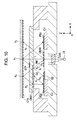
- Fig. 10 is a schematic cross-sectional view showing the optical elements of the displacement measurement apparatus according to the fourth exemplary embodiment.
- the apparatus shown in Figs. 9 and 10 basically includes the same elements as those in the first to third exemplary embodiments, the elements being denoted by the same reference numerals.
- the apparatus further includes a light splitter HM, a first deflector GBS1, a second deflector G2, a third deflector G3, and a light-blocking member STP.
- displacements not only in the Y and Z directions but also in the X direction are to be measured.
- the Y direction corresponds to the first direction
- the Z direction corresponds to the second direction
- the X direction corresponds to the third direction.
- the reflector FM employed in the first to third exemplary embodiments is omitted.
- the apparatus includes the light splitter HM, which transmits and reflects the third diffracted beam l 3 and thus splits the third diffracted beam l 3 into two beams, and the light-blocking member STP, which blocks the first diffracted beam l 1 diffracted by the second diffraction grating GTO and undergone -1st-order diffraction in the -Y direction.
- the light splitter HM of the fourth exemplary embodiment is a half mirror.
- the length of an optical path of the third diffracted beam l 3 from the point of transmission through the light splitter HM to the point of incidence on the second photodetector PDz is equal to the length of an optical path of the third diffracted beam l 3 from the point of reflection by the light splitter HM to the point of incidence on the second photodetector PDz. That is, the light splitter HM, the first deflector GBS1, and the third deflector G3 are provided in a particular plane defined at the midpoint between the first diffraction grating GBSO and the second diffraction grating GTO.
- the fourth exemplary embodiment concerns an application of the measurement principle of the Michelson interferometer in which the length of an optical path of measurement light traveling via a surface to be measured (the second diffraction grating GTO) is equal to the length of an optical path of reference light traveling via a reference surface (the second deflector G2).
- the third diffracted beam l 3 diffracted in the -Y direction by the first diffraction grating GBSO and incident at point P 3 on the light splitter HM is transmitted through the light splitter HM, and is specularly reflected (i.e., undergoes 0th-order reflective diffraction) at point P 4 on the second diffraction grating GTO.
- the beam specularly reflected at point P 4 is incident on the first deflector GBS1, thus produces a beam diffracted and deflected in the +Y direction, and is then perpendicularly incident on the second photodetector PDz.
- the third diffracted beam l 3 reflected by the light splitter HM strikes the second deflector G2 at point P 6 and the third deflector G3 at point P 7 , and is then obliquely incident on the second photodetector PDz.
- the first diffracted beam l 1 which would be incident on the second photodetector PDz in the first to third exemplary embodiments, is blocked by the light-blocking member STP after undergoing reflective diffraction in the -Y direction on the second diffraction grating GTO. Therefore, the first diffracted beam l 1 does not reach the second photodetector PDz.
- the two beams incident on the second photodetector PDz interfere with each other, producing interference fringes thereon.
- the interference fringes also move.
- sine-wave signals are output from the second photodetector PDz.
- the phases of the signals are calculated by the corresponding calculation unit CU.
- the optical paths along which the two beams incident on the second photodetector PDz travel are geometrically of the same length.
- optical elements need to be arranged precisely in accordance with the wavelength of light emitted from the light source LS.
- the light source LS may be an SLD or the like, which have low coherence. In that case, effects of multiple interference caused by unnecessary beams from a grating interferometer or a Michelson interferometer can be eliminated. Accordingly, measurement with much higher accuracy is realized.
- the Y-direction period of the periodic pattern on each of the first and second diffraction gratings GBSO and GTO and the tooth period of the second photodetector PDz are set to be the same as each other.
- ⁇ d P y ⁇ ⁇ 2 1 cos sin - 1 ⁇ / P y ⁇ ⁇ z
- Py denotes the Y-direction period of the periodic pattern on the second diffraction grating GTO.
- Z-direction displacement is measured by utilizing the beams from the first diffraction grating GBSO diffracted in the Y direction.
- Z-direction displacement may be measured by utilizing beams diffracted in any other directions. For example, referring to Fig. 14 , beams diffracted in the X direction, beams diffracted in the X+Y direction, or beams diffracted in the X-Y direction may be utilized.
- the light splitter HM that splits the third diffracted beam l 3 so as to measure X-direction displacement may be a diffraction grating.
- Fig. 11 is a schematic cross-sectional view showing optical elements of a displacement measurement apparatus according to a fifth exemplary embodiment of the present invention.
- the fifth exemplary embodiment is a variation of the fourth exemplary embodiment and concerns measurement of displacements in the Y and Z directions.
- the Y direction corresponds to the first direction
- the Z direction corresponds to the second direction.
- the fifth exemplary embodiment concerns an application of the measurement principle of the Michelson interferometer in which interference light produced by two beams resulting from splitting of the third diffracted beam l 3 incident on the light splitter HM is utilized for measurement of displacement in the Z direction, and the lengths of optical paths of the two beams are equal to each other.
- the third diffracted beam l 3 diffracted in the -Y direction by the first diffraction grating GBSO and incident at point P 3 on the light splitter HM is transmitted through the light splitter HM, and is specularly reflected (i.e., undergoes 0th-order reflective diffraction) at point P 4 on the second diffraction grating GTO.
- the beam specularly reflected at point P 4 is obliquely incident on the second photodetector PDz.
- the third diffracted beam l 3 reflected at point P 3 on the light splitter HM strikes a fourth deflector G4 at point P 6 and a fifth deflector G5 at point P 7 , and is then perpendicularly incident on the second photodetector PDz.
- the optical paths along which the two beams incident on the second photodetector PDz travel can be designed so as to geometrically have the same length by optimizing the pattern pitches and positions of the fourth and fifth deflectors G4 and G5.
- the two beams incident on the second photodetector PDz interfere with each other, producing interference fringes thereon.
- the interference fringes also move.
- sine-wave signals are output from the second photodetector PDz.
- the phases of the signals are calculated by the corresponding calculation unit CU.
- the optical paths along which the two beams to be incident on the second photodetector PDz travel are geometrically of the same length. Therefore, the light source LS may be an SLD or the like, which have low coherence. In that case, effects of multiple interference caused by unnecessary beams from a grating interferometer or a Michelson interferometer can be eliminated. Accordingly, measurement with much higher accuracy is realized.
- Fig. 12 is a schematic perspective view showing optical elements of a displacement measurement apparatus according to a sixth exemplary embodiment of the present invention.
- the first to fifth exemplary embodiments concern the case where displacements at least in the Y and Z directions are to be measured.
- the sixth exemplary embodiment concerns a case where displacements in the X and Y directions, i.e., displacements in two directions defined within the plane where the second diffraction grating GTO is provided, are to be measured.
- the Y direction corresponds to the first direction
- the X direction corresponds to the second direction. Measurements of the Y- and X-direction displacements are the same as in the third exemplary embodiment.
- the first and second diffracted beams l 1 and l 2 behave in the same way as in the third exemplary embodiment, while the third diffracted beam l 3 does not.
- the third diffracted beam l 3 is diffracted and deflected in the +X direction, and is incident on the second photodetector PDx.
- the photodetector PDx that measures the X-direction displacement serves as the second photodetector, unlike in the third exemplary embodiment.
- the first photodetector PDy receives interference light produced by the first and second diffracted beams l 1 and l 2 that are reflected and diffracted by the second diffraction grating GTO, and outputs sine-wave signals to the corresponding calculation unit CU.
- the calculation unit CU calculates the phases of the signals, whereby displacement information with respect to the Y direction is obtained.
- the second photodetector PDx receives interference light produced by the first and third diffracted beams l 1 and l 3 that are reflected and diffracted by the second diffraction grating GTO, and outputs sine-wave signals to the corresponding calculation unit CU.
- the calculation unit CU calculates the phases of the signals, whereby displacement information with respect to the X direction is obtained.
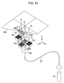
- Fig. 13 is a schematic perspective view showing optical elements of a displacement measurement apparatus according to a seventh exemplary embodiment of the present invention.
- the light source LS is provided at a position remote from the optical system, and light from the light source LS is guided by an optical fiber OF to the optical system. Specifically, an output end of the optical fiber OF is placed at the position where the light source would be placed in the other exemplary embodiments, and the light from the light source LS is supplied from the outside through the optical fiber OF. That is, the displacement measurement apparatus of the seventh exemplary embodiment does not include the light source LS.
- the light source LS is provided outside the displacement measurement apparatus.
- the light source LS can be placed at a position remote from the optical system constituted by various optical elements including the first and second diffraction gratings GBSO and GTO. Therefore, the optical system is less affected by heat generated from the light source LS. Such a configuration advantageously reduces adverse effects of the heat on measurement accuracy.
- the optical fiber OF is provided between the light source LS and a position corresponding to the lens LNS of the third exemplary embodiment.
- the optical fiber OF may be provided between the lens LNS and the first diffraction grating GBSO.
- the displacement measurement apparatuses according to the above exemplary embodiments of the present invention can be applied to apparatuses that are required to detect nanometer- or subnanometer-order displacements: for example, an industrial mechanical stage, a high-accuracy shape measurement apparatus, a microscope stage, a high-accuracy machining apparatus, a semiconductor exposure apparatus, a semiconductor manufacturing apparatus, and the like.
- Fig. 15 schematically shows an exemplary exposure apparatus including any of the displacement measurement apparatuses according to the above exemplary embodiments.
- the exposure apparatus includes a light source LS, an illumination optical system IL that illuminates a reticle R, a projection optical system PL that projects light applied by the illumination optical system IL onto a wafer W, a reticle stage RS that holds and moves the reticle R, a wafer stage WS that holds and moves the wafer W, an encoder scale (a second diffraction grating) SCL, an encoder detection-optical-system head HD (including a light source, a first diffraction grating, and photodetectors), a reference base block BASE1, and a base block BASE2 that holds the encoder scale SCL.
- a light source LS an illumination optical system IL that illuminates a reticle R
- a projection optical system PL that projects light applied by the illumination optical system IL onto a wafer W
- a reticle stage RS that holds and moves the reticle R
- a wafer stage WS that holds and moves the wafer W
- the head HD is secured on a side face of the wafer stage WS, and, while the wafer stage WS is moved two-dimensionally, laser light is applied to the scale SCL and diffracted light from the scale SCL is received by the head HD.
- positional information with respect to the horizontal direction and the gap direction is obtained.
Landscapes
- Physics & Mathematics (AREA)
- General Physics & Mathematics (AREA)
- Length Measuring Devices By Optical Means (AREA)
- Optical Transform (AREA)
Abstract
A displacement measurement apparatus includes a first diffraction grating (GBS0) transmitting light from a light source and producing diffracted beams including first to third diffracted beams output in different directions. The apparatus further includes a second diffraction grating (GT0) movable together with an object to be measured, provided in a plane parallel to the first diffraction grating (GBSO) and reflecting the first to third diffracted beams transmitted through the first diffraction grating (GBSO). The apparatus also includes a first photodetector (PDy) receiving the first and second diffracted beams diffracted by the second diffraction grating(GTO); a second photodetector (PDz) receiving at least the third diffracted beam transmitted through the first diffraction grating (GBSO). Finally the apparatus includes a calculation unit (CU) calculating displacement of the object in a first direction in accordance with the beams received by the first photodetector (PDy), and displacement of the object in a second direction, different from the first direction, in accordance with the beam received by the second photodetector (PDz).
Description
- The present invention relates to measurement apparatuses that obtain displacement information by converting relative displacements of objects into periodic signals and counting the periodic signals, and also relates to multi-axial displacement measurement apparatuses that measure displacements in multiple directions.
- Known examples of a displacement measurement apparatus that measures relative displacement of a mechanical stage employ optical encoders and laser interferometers.
- An exemplary displacement measurement apparatus that measures displacement along a single axis is disclosed in Japanese Patent Laid-Open No.
6-18291 Fig. 4 therein). This apparatus is an interference encoder, and causes a 0th-order diffracted light beam and a +1st-order diffracted light beam resulting from light transmitted through a diffraction grating to be incident on another diffraction grating provided on a scale attached to an object to be measured, whereby a +1st-order reflected diffracted light beam resulting from the 0th-order diffracted light beam and a -1st-order reflected diffracted light beam resulting from the +1st-order diffracted light beam interfere with each other. The intensity of interference light varies with the amount of displacement. Therefore, displacement of the object is measured by detecting the intensity of interference light with a photodetector. - Another displacement measurement apparatus is disclosed in Japanese Patent Laid-Open No.
2007-171206 Figs. 1 and 19 therein). This apparatus measures displacement in one direction (along the X axis) within a plane in which a diffraction grating that moves together with an object to be measured is provided, and displacement in another direction (along the Z axis) orthogonal to the plane. The displacements in the X and Z directions, are measured with respective measurement systems, each including a light source, an interferometer core, a polarization conversion device, a detector, and so forth. Specifically, two measurement systems are provided in parallel, and two light beams are applied, at Littrow angles, to a diffraction grating, whereby reflected diffracted light beams are produced. Subsequently, two pieces of displacement information as composite information with respect to the X and Z directions, i.e., Z+X information and Z-X information, are obtained. Thus, X-direction displacement information and Z-direction displacement information are calculated. - Japanese Patent Laid-Open No.
2007-171206 - Another displacement measurement apparatus that measures displacements in two directions within a plane in which a diffraction grating that moves together with an object to be measured is provided is disclosed in Japanese Patent Laid-Open No.
6-288722 Fig. 1 therein). This apparatus measures displacements of the object in two directions (along the X and Y axes) that are orthogonal to each other within the plane. A diffraction grating having a checkerboard pattern and configured to move together with the object is provided in a plane containing the X and Y axes. Light is made to be orthogonally incident on the diffraction grating. Light transmitted through the diffraction grating and diffracted in the X direction produces a +1st-order diffracted light beam and a -1st-order diffracted light beam, which are further made to be incident on respective incidence diffraction gratings. The +1st-order diffracted light beam and the -1st-order diffracted light beam are introduced from the incidence diffraction gratings into respective strip waveguides provided in the XY plane, and are subsequently made to interfere with each other at a coupler. By detecting the resulting interference light with a detector, X-direction displacement is measured. The same applies in Y-direction measurement: light is diffracted in the Y direction into a +1st-order diffracted light beam and a -1st-order diffracted light beam, which are introduced into respective strip waveguides and are subsequently made to interfere with each other at a coupler. - The displacement measurement apparatus disclosed in Japanese Patent Laid-Open No.
2007-171206 - The displacement measurement apparatus disclosed in Japanese Patent Laid-Open No.
6-288722 - The present invention provides a displacement measurement apparatus capable of measuring, with a single measurement system, displacement in a direction defined within a plane where a diffraction grating is provided and displacement in a direction perpendicular to the plane, by utilizing a plurality of diffracted light beams that are produced from light emitted from a light source and diffracted through the diffraction grating.
- The present invention also provides a displacement measurement apparatus having a simple and compact configuration and capable of measuring displacements in two directions defined within a plane where a diffraction grating is provided.
- The present invention in its first aspect provides a displacement measurement apparatus as specified in claims 1 to 11.
- The present invention in its second aspect provides an exposure apparatus as specified in
claim 12. - In the first aspect of the present invention, displacements in different directions are obtained as periodic signals that are independent from each other but are generated simultaneously. Therefore, the time required for calculation by a CPU or an FPGA can be reduced. Furthermore, compared with an apparatus including a plurality of measurement systems, the displacement measurement apparatus according to the above aspect of the present invention, including a single measurement system, is constituted by a smaller number of optical components that are substantially common to measurements in different directions. Therefore, the size of the apparatus can be reduced. Moreover, since detections for different directions are performed at a substantially single position, errors due to inclination and the like can be largely reduced.
- Further features of the present invention will become apparent from the following description of exemplary embodiments with reference to the attached drawings.
-
Fig. 1 is a schematic perspective view showing optical elements of a displacement measurement apparatus according to a first exemplary embodiment of the present invention. -
Fig. 2 is a schematic cross-sectional view showing the optical elements of the displacement measurement apparatus according to the first exemplary embodiment. -
Fig. 3 illustrates diffraction and light-splitting functions of a first diffraction grating GBSO. -
Fig. 4 includes schematic perspective views showing variations of the first diffraction grating GBSO and a second diffraction grating GTO. -
Fig. 5 illustrates diffraction and light-splitting functions of the second diffraction grating GTO. -
Fig. 6 illustrates two light beams incident on a photodetector and interference fringes produced by the two light beams on photodetector elements. -
Fig. 7 is a schematic cross-sectional view showing optical elements of a displacement measurement apparatus according to a second exemplary embodiment of the present invention. -
Fig. 8 is a schematic perspective view showing optical elements of a displacement measurement apparatus according to a third exemplary embodiment of the present invention. -
Fig. 9 is a schematic perspective view showing optical elements of a displacement measurement apparatus according to a fourth exemplary embodiment of the present invention. -
Fig. 10 is a schematic cross-sectional view showing the optical elements of the displacement measurement apparatus according to the fourth exemplary embodiment. -
Fig. 11 is a schematic cross-sectional view showing optical elements of a displacement measurement apparatus according to a fifth exemplary embodiment of the present invention. -
Fig. 12 is a schematic perspective view showing optical elements of a displacement measurement apparatus according to a sixth exemplary embodiment of the present invention. -
Fig. 13 is a schematic perspective view showing optical elements of a displacement measurement apparatus according to a seventh exemplary embodiment of the present invention. -
Fig. 14 shows an arrangement of an optical system included in an exemplary displacement measurement apparatus that measures displacements by utilizing diffracted light beams in eight directions. -
Fig. 15 schematically shows an exemplary exposure apparatus including any of the displacement measurement apparatuses according to the exemplary embodiments. - A displacement measurement apparatus according to a general embodiment of the present invention includes a first diffraction grating, a second diffraction grating, a first photodetector, a second photodetector, and a calculation unit.
- The first diffraction grating transmits light emitted from a light source, and produces a plurality of diffracted light beams, including first, second, and third diffracted beams, to be output in different directions.
The first, second, and third diffracted beams further undergo diffraction, reflection, and the like, thereby producing interference light. By measuring the interference light, displacements in a plurality of directions can be measured. That is, a single measurement system measures displacements in a plurality of directions. - The second diffraction grating is provided in a plane parallel to the first diffraction grating, and is movable together with an object to be measured. The second diffraction grating reflects the first, second, and third diffracted beams produced by the first diffraction grating.
- The first photodetector receives the first and second diffracted beams that are diffracted by the second diffraction grating. The second photodetector receives at least the third diffracted beam. The first and second photodetectors are provided for measuring displacements of the object in respective directions. The beams received by each of the photodetectors represent displacement in one direction. This means that there is no need to calculate displacement in one direction in accordance with beams received by a plurality of photodetectors. Accordingly, real-time control of the object in a plurality of directions is realized.
- The calculation unit calculates displacement of the object in a first direction in accordance with the beams received by the first photodetector, and displacement of the object in a second direction, different from the first direction, in accordance with the beams received by the second photodetector. Since the beams received by each of the photodetectors represent displacement in one direction, the calculation unit may include two separate units: a unit responsible for calculation of displacement in the first direction, and a unit responsible for calculation of displacement in the second direction.
- Exemplary embodiments of the present invention will now be described with reference to the drawings. It should be noted that the exemplary embodiments described below do not limit the present invention.
-
Fig. 1 is a schematic perspective view showing optical elements of a displacement measurement apparatus according to a first exemplary embodiment of the present invention.Fig. 2 is a schematic cross-sectional view showing the optical elements of the displacement measurement apparatus according to the first exemplary embodiment. -
Figs. 1 and2 each show a first diffraction grating GBSO, a second diffraction grating GTO, a first photodetector PDy, a second photodetector PDz, calculation units CU, a reflector FM, a lens LNS, and a light source LS. The X axis and the Y axis lie in a plane where the first and second diffraction gratings GBSO and GTO are provided, and the Z axis is perpendicular to the plane. In the first exemplary embodiment, displacement in the Y direction and displacement in the Z direction are to be measured. The Y direction corresponds to the first direction, and the Z direction corresponds to the second direction. - The elements included in the displacement measurement apparatus according to the first exemplary embodiment will now be individually described with reference to the drawings.
- The first diffraction grating GBSO is provided in a plane containing the X and Y axes, and has a grating pattern of fine structures periodically arranged in the X and Y directions. The lens LNS is positioned relative to the first diffraction grating GBSO in the Z direction, and the light source LS is positioned farther from the first diffraction grating GBSO than the lens LNS. The fine periodic grating pattern of the first diffraction grating GBSO is provided on a surface thereof remote from the lens LNS and the light source LS.
- Referring to
Fig. 3 , the first diffraction grating GBSO produces a plurality of light beams from a single light beam. Referring toFig. 4 , the first diffraction grating GBSO is provided as a substrate having a micron-order pattern in which two-dimensional fine figures are arranged or three-dimensional fine structures are two-dimensionally arranged. A diffractive optical element having such a pattern of fine figures/structures can be prepared by processing a quartz-glass substrate by photolithographic selective etching, a replica method, or the like. - The second diffraction grating GTO is provided on a side opposite the lens LNS and the light source LS with respect to the first diffraction grating GBSO so as to be parallel to the first diffraction grating GBSO, and has on a surface thereof facing the first diffraction grating GBSO fine periodic structures arranged in a grating pattern at least in the Y direction. The second diffraction grating GTO moves together with the object to be measured. Therefore, by measuring the displacement of the second diffraction grating GTO, displacement of the object can be measured.
- Unlike the first diffraction grating GBSO that transmits and diffracts light, the second diffraction grating GTO reflects and diffracts light. However, referring to
Fig. 5 , the second diffraction grating GTO also splits a single light beam into a plurality of light beams, as does the first diffraction grating GBSO, and is provided as a substrate having a micron-order pattern in which two-dimensional fine figures are arranged or three-dimensional fine structures are two-dimensionally arranged, such as those shown inFig. 4 . The pattern can be formed by the same method as for the pattern of the first diffraction grating GBSO. - The diffracted light beams shown in
Figs. 3 and5 are representative beams, and in general there are other beams produced in the outside area of the shown beams. The distribution of the amount of light of such beams is changeable by appropriately changing the designs, including the shape of the fine figures/structures, the ratio of the gap between the figures/structures, the amount of level difference, and the like. That is, the designs can be optimized to efficiently produce necessary light beams.
Fig. 4 shows variations of the fine pattern, including a pattern of transmissive and nontransmissive fine figures, a pattern of fine two-tiered structures, a pattern of structures with a changed amount of level difference, a pattern of structures with a changed ratio of the gap between structures, a pattern of structures in a changed arrangement, and a pattern of fine three-tiered solid structures. - The first photodetector PDy and the second photodetector PDz of the first exemplary embodiment are provided in the plane where the first diffraction grating GBSO is provided, and receive the light diffracted by being transmitted through the first diffraction grating GBSO and then reflected by the second diffraction grating GTO. The first photodetector PDy measures displacement of the object in the Y direction. The second photodetector PDz measures displacement of the object in the Z direction.
- The first and second photodetectors PDy and PDz can be configured in various ways, as long as they can measure changes in interference fringes produced by interference between a plurality of light beams. In the first exemplary embodiment, referring to
Fig. 6 , the first and second photodetectors PDy and PDz each include four comb-shaped photodetector elements A(+), A(-), B(+), and B(-) having identical shapes. The four comb-shaped photodetector elements are staggered with respect to each other by 1/4 of the pitch of teeth thereof. The width of each tooth corresponds to 1/4 or smaller of the tooth period. Thus, light falls onto all the teeth of the four elements. In the first photodetector PDy, when the second diffraction grating GTO moves relative thereto in the Y direction, sine-wave periodic signals that are out of phase with each other by 1/4 period are output from the four photodetector elements, respectively. In accordance with these signals, displacement in the Y direction can be measured. In the second photodetector PDz, when the second diffraction grating GTO moves relative thereto in the Z direction, sine-wave periodic signals that are out of phase with each other by 1/4 period are output from the four photodetector elements, respectively. In accordance with these signals, displacement in the Z direction can be measured. - The photodetectors PDy and PDz according to the first exemplary embodiment of the present invention may each include only two or three, instead of four, comb-shaped photodetector elements, as long as a plurality of signals that are out of phase with each other can be obtained. In addition, the photodetectors PDy and PDz may be each constituted by plate-like elements having slits, instead of comb-shaped elements. Photodetectors constituted by comb-shaped elements are advantageous in that they cause little loss of light, leading to improvement in measurement accuracy, and are therefore suitable for use in controlling, for example, stages of exposure apparatuses, in which highly accurate measurement is required. Whereas, photodetectors constituted by plate-like elements having slits are advantageous in that the assembly cost can be reduced.
- The calculation units CU calculate displacements of the object in the different directions in accordance with the signals output from the first and second photodetectors PDy and PDz. The calculation units CU may be provided at any position in the displacement measurement apparatus. In the first exemplary embodiment, a unit that calculates displacement in the Y direction is provided integrally with the first photodetector PDy, and a unit that calculates displacement in the Z direction is provided integrally with the second photodetector PDz.
- The reflector FM is provided between the first diffraction grating GBSO and the second diffraction grating GT0, specifically, at the midpoint between the two. The reflector FM has on both sides thereof reflective surfaces so as to reflect both of the light from the first diffraction grating GBSO and the light from the second diffraction grating GTO, the reflective surfaces extending parallel to the first and second diffraction gratings GBSO and GTO.
- The light source LS is provided such that the light therefrom is to be incident on the first diffraction grating GBSO through the lens LNS. The light source LS may be any of the following, in accordance with optical conditions: a laser diode (LD), a vertical-cavity surface-emitting laser (VCSEL), a superluminescent diode (SLD), and the like. In the first exemplary embodiment, an LD is employed as the light source LS. The lens LNS is provided between the light source LS and the first diffraction grating GBSO, under such optical conditions that light emitted from the light source LS is incident as parallel light on the first diffraction grating GBSO.
- The light source LS and the lens LNS may be provided either inside or outside the displacement measurement apparatus. In the first exemplary embodiment, the displacement measurement apparatus includes the light source LS and the lens LNS.
- The principle of measuring displacement of the object to be measured through the foregoing elements will now be described in order in which light travels.
- Measurement of displacement in the Y direction will first be described.
- Divergent light beams emitted from the light source LS are converted into parallel light beams by the lens LNS and are incident on the first diffraction grating GBSO.
- The beams incident on the first diffraction grating GBSO is transmitted therethrough and produce a plurality of diffracted beams, including a first diffracted beam l1, a second diffracted beam l2, and a third diffracted beam l3, that are output in directions different from each other. In the first exemplary embodiment, the first diffracted beam l1 is transmitted through the first diffraction grating GBSO and travels straight ahead, producing a 0th-order diffracted beam; the second diffracted beam l2 is diffracted in the +Y direction, producing a 1st-order diffracted beam; and the third diffracted beam l3 is diffracted in the -Y direction, producing a -1st-order diffracted beam.
- The first diffracted beam l1 produced by the first diffraction grating GBSO travels straight ahead and is incident at point P1 on the second diffraction grating GTO provided on a relative movement scale that moves together with the object to be measured. The second diffracted beam l2 is diffracted and deflected by the first diffraction grating GBSO and is incident at point P2 on the second diffraction grating GTO. The third diffracted beam l3 is diffracted and deflected by the first diffraction grating GBSO and is incident at point P3 on a surface of the reflector FM facing the first diffraction grating GBSO.
- The first diffracted beam l1 incident at point P1 is reflected by the second diffraction grating GTO and produces a +1st-order diffracted beam that is diffracted in the +Y direction and a -1st-order diffracted beam that is diffracted in the -Y direction. The +1st-order diffracted beam is obliquely incident on the first photodetector PDy. The second diffracted beam l2 incident at point P2 undergoes -1st-order diffraction and is perpendicularly incident on the first photodetector PDy.
- The two beams incident on the first photodetector PDy interfere with each other, producing interference fringes thereon. When the second diffraction grating GTO moves in the Y direction, the interference fringes also move. With the movement of the interference fringes, sine-wave signals are output from the first photodetector PDy. The phases of the signals are calculated by the corresponding calculation unit CU. Thus, displacement information with respect to the Y direction is obtained.
- Referring to
Fig. 6 , the period, height, and the like of the periodic pattern on each of the first and second diffraction gratings GBSO and GTO are set such that the period of the interference fringes produced as above becomes the same as the tooth period of the first photodetector PDy. For example, if the Y-direction period Py of the first diffraction grating GBSO and the Y-direction period of the second diffraction grating GTO are the same, the period of the interference fringes produced as described above is also the same as the foregoing two. Therefore, in the first exemplary embodiment, the Y-direction period of the periodic pattern on the first diffraction grating GBSO, the Y-direction period of the periodic pattern on the second diffraction grating GTO, and the tooth period of the first photodetector PDy are set to be the same as each other. - Assuming that the interference fringes move by Δd when the second diffraction grating GTO moves in the Y direction by Δy, the following relationship holds:

- In this case, the Y-direction displacement amount Δy0 with which a single period of a sine-wave signal is generated by the first photodetector PDy is expressed as follows:

where Py denotes the Y-direction period of the periodic pattern on the second diffraction grating GTO. - Next, measurement of displacement in the Z direction will be described.
- The third diffracted beam l3 incident at point P3 on the surface of the reflector FM facing the first diffraction grating GBSO is reflected by the reflector FM and is obliquely incident on the second photodetector PDz. Meanwhile, the first diffracted beam l1 incident at point P1 is reflected by the second diffraction grating GTO and produces the +1st-order diffracted beam that is diffracted in the +Y direction and the -1st-order diffracted beam that is diffracted in the -Y direction. The -1st-order diffracted beam is incident at point P4 on the surface of the reflector FM facing the second diffraction grating GTO and is reflected by the reflector FM. The first diffracted beam l1 reflected at point P4 is then incident at point P5 on the second diffraction grating GTO, and produces a +1st-order diffracted beam. The +1st-order diffracted beam is then output in the -Z direction and is perpendicularly incident on the second photodetector PDz.
- The two beams incident on the second photodetector PDz interfere with each other, producing interference fringes thereon. When the second diffraction grating GTO moves in the Z direction, the interference fringes also move. With the movement of the interference fringes, sine-wave signals are output from the second photodetector PDz. The phases of the signals are calculated by the corresponding calculation unit CU. Thus, displacement information with respect to the Z direction is obtained.
- The period, height, and the like of the periodic pattern on each of the first and second diffraction gratings GBSO and GTO are set such that the period of the interference fringes produced as above becomes the same as the tooth period of the second photodetector PDz. In the first exemplary embodiment, the beams diffracted in the Y direction are utilized for measurement of displacement in the Z direction. Therefore, the Y-direction period of the periodic pattern on each of the first and second diffraction gratings GBSO and GTO and the tooth period of the second photodetector PDz are set to be the same as each other.
- Assuming that the interference fringes move by Δd when the second diffraction grating GTO moves in the Z direction by Δz, the following relationship holds:

where λ denotes the center wavelength of light from the light source LS, and Py denotes the Y-direction period of the periodic pattern on the second diffraction grating GTO. - In this case, the Z-direction displacement amount Δz0 with which a single period of a sine-wave signal is generated by the second photodetector PDz is expressed as follows:

- Thus, periodic signals representing the Y-direction displacement and the Z-direction displacement of the second diffraction grating GTO are output simultaneously.
- In the first exemplary embodiment, Z-direction displacement is measured by utilizing the beams from the first diffraction grating GBSO diffracted in the Y direction. Alternatively, Z-direction displacement may be measured by utilizing beams diffracted in any other directions. For example, referring to
Fig. 14 , beams diffracted in the X direction, beams diffracted in the X+Y direction, or beams diffracted in the X-Y direction may be utilized. -
Fig. 7 is a schematic cross-sectional view showing optical elements of a displacement measurement apparatus according to a second exemplary embodiment of the present invention. - The second exemplary embodiment is a variation of the first exemplary embodiment and concerns measurement of displacements in the Y and Z directions. The Y direction corresponds to the first direction, and the Z direction corresponds to the second direction. In the second exemplary embodiment, the reflector FM is provided in the plane where the first diffraction grating GBSO and the first and second photodetectors PDy and PDz are provided. The reflector FM has a reflective surface on one side thereof facing the second diffraction grating GTO so as to reflect light from the second diffraction grating GTO. The second exemplary embodiment differs from the first exemplary embodiment in the optical system provided for Z-direction measurement, but is the same as the first exemplary embodiment in the arrangement of the first and second diffraction gratings GBSO and GTO and the first and second photodetectors PDy and PDz, and the configuration of the optical system provided for Y-direction measurement.
- Measurement of displacement in the Z direction will now be described.
- The third diffracted beam l3 diffracted in the -Y direction by the first diffraction grating GBSO is specularly reflected (i.e., undergoes 0th-order reflective diffraction) at point P3 on the second diffraction grating GTO and is obliquely incident on the second photodetector PDz. Meanwhile, the first diffracted beam l1 incident at point P1 is reflected by the second diffraction grating GTO and produces a +1st-order diffracted beam that is diffracted in the +Y direction and a -1st-order diffracted beam that is diffracted in the -Y direction. The -1st-order diffracted beam is incident at point P4 on the surface of the reflector FM facing the second diffraction grating GTO and is reflected thereat. The first diffracted beam l1 reflected at point P4 is incident at point P5 on the second diffraction grating GTO, and produces a +1st-order diffracted beam. The +1st-order diffracted beam is output in the -Z direction and is perpendicularly incident on the second photodetector PDz.
- The two beams incident on the second photodetector PDz interfere with each other, producing interference fringes thereon. When the second diffraction grating GTO moves in the Z direction, the interference fringes also move. With the movement of the interference fringes, sine-wave signals are output from the second photodetector PDz. The phases of the signals are calculated by the corresponding calculation unit CU. Thus, displacement information with respect to the Z direction is obtained.
- In the second exemplary embodiment, as in the first exemplary embodiment, the Y-direction period of the periodic pattern on each of the first and second diffraction gratings GBSO and GTO and the tooth period of the second photodetector PDz are set to be the same as each other. When the second diffraction grating GTO moves in the Z direction by Δz, the difference in each of the two beams is the amount of displacement along an optical path extending in the Z direction. Therefore, when the interference fringes move by Δd, the following relationship holds:

where λ denotes the center wavelength of light from the light source LS. - In this case, the Z-direction displacement amount Δz0 with which a single period of a sine-wave signal is generated by the second photodetector PDz is expressed as follows:

where Py denotes the Y-direction period of the periodic pattern on the second diffraction grating GTO. - In the second exemplary embodiment, a support member or the like for supporting the reflector FM, which is not provided between the first diffraction grating GBSO and the second diffraction grating GTO, is unnecessary in a space between the first and second diffraction gratings GBSO and GTO. This reduces the number of components to be included in the apparatus, realizes a simple configuration, and enables easy assembly.
- In the second exemplary embodiment, Z-direction displacement is measured by utilizing the beams from the first diffraction grating GBSO diffracted in the Y direction. Alternatively, Z-direction displacement may be measured by utilizing beams diffracted in any other directions. For example, referring to
Fig. 14 , beams diffracted in the X direction, beams diffracted in the X+Y direction, or beams diffracted in the X-Y direction may be utilized. -
Fig. 8 is a schematic perspective view showing optical elements of a displacement measurement apparatus according to a third exemplary embodiment of the present invention. - In the third exemplary embodiment, displacements not only in the Y and Z directions but also in the X direction are to be measured. The Y direction corresponds to the first direction, the Z direction corresponds to the second direction, and the X direction corresponds to a third direction.
- The plurality of diffracted beams produced when light is transmitted through the first diffraction grating GBSO include, in addition to the first to third diffracted beams l1 to l3, a fourth diffracted beam l4 that undergoes 1st-order diffraction in the +X direction, unlike the first to third diffracted beams l1 to l3. The first diffracted beam l1 that is transmitted through the first diffraction grating GBSO and travels straight ahead and the fourth diffracted beam l4 are received as interference light by a third photodetector PDx, whereby X-direction displacement is measured.
- The fourth diffracted beam l4 is incident at point P6 on the second diffraction grating GTO, producing a beam that undergoes -1st-order diffraction in the +X direction and is perpendicularly incident on the third photodetector PDx. Meanwhile, the first diffracted beam l1 that is incident at point P1 on the second diffraction grating GTO and undergoes +1st-order diffraction in the +X direction is obliquely incident on the third photodetector PDx. The two beams received by the third photodetector PDx interfere with each other, producing interference fringes thereon.
- The third photodetector PDx is configured to have a tooth period the same as the period of the interference fringes produced as described above. Four comb-shaped photodetector elements included in the third photodetector PDx output respective sine-wave periodic signals that are out of phase with each other by 90 degrees. Therefore, by counting the numbers of waves included in the periodic signals and determining the phases of the sine waves with the corresponding calculation unit CU, displacement information with respect to the X direction is obtained.
- The second diffraction grating GTO of the third exemplary embodiment needs to have on the surface thereof facing the first diffraction grating GBSO a periodic grating pattern of fine structures arranged not only in the Y direction but also in the X direction. To measure displacement in the X direction, the second diffraction grating GTO needs to cause reflective diffraction in the X direction.
- In the third exemplary embodiment, Z-direction displacement is measured by utilizing the beams from the first diffraction grating GBSO diffracted in the Y direction. Alternatively, Z-direction displacement may be measured by utilizing beams diffracted in any other directions. For example, referring to
Fig. 14 , beams diffracted in the X direction, beams diffracted in the X+Y direction, or beams diffracted in the X-Y direction may be utilized. Furthermore, the number of axes along which measurement is performed can be increased easily. Simultaneous detection along four or more axes with a single optical system is also possible. For example, in addition to measurements in the X, Y, and the Z directions, measurements in the X+Y direction, the X-Y direction, and the like can be performed. -
Fig. 9 is a schematic perspective view showing optical elements of a displacement measurement apparatus according to a fourth exemplary embodiment of the present invention.Fig. 10 is a schematic cross-sectional view showing the optical elements of the displacement measurement apparatus according to the fourth exemplary embodiment. - The apparatus shown in
Figs. 9 and10 basically includes the same elements as those in the first to third exemplary embodiments, the elements being denoted by the same reference numerals. The apparatus further includes a light splitter HM, a first deflector GBS1, a second deflector G2, a third deflector G3, and a light-blocking member STP. - In the fourth exemplary embodiment, displacements not only in the Y and Z directions but also in the X direction are to be measured. The Y direction corresponds to the first direction, the Z direction corresponds to the second direction, and the X direction corresponds to the third direction.
- In the fourth exemplary embodiment, the reflector FM employed in the first to third exemplary embodiments is omitted. Instead, the apparatus includes the light splitter HM, which transmits and reflects the third diffracted beam l3 and thus splits the third diffracted beam l3 into two beams, and the light-blocking member STP, which blocks the first diffracted beam l1 diffracted by the second diffraction grating GTO and undergone -1st-order diffraction in the -Y direction. The light splitter HM of the fourth exemplary embodiment is a half mirror. Two beams, produced by the third diffracted beam l3 transmitted through and reflected by the light splitter HM, respectively, in combination form interference light, which is received by the second photodetector PDz. Thus, displacement in the Z direction is measured. Measurement of displacement in the Y direction is the same as in the first to third exemplary embodiment, and measurement of displacement in the X direction is the same as in the third exemplary embodiment.
- In the fourth exemplary embodiment, the length of an optical path of the third diffracted beam l3 from the point of transmission through the light splitter HM to the point of incidence on the second photodetector PDz is equal to the length of an optical path of the third diffracted beam l3 from the point of reflection by the light splitter HM to the point of incidence on the second photodetector PDz. That is, the light splitter HM, the first deflector GBS1, and the third deflector G3 are provided in a particular plane defined at the midpoint between the first diffraction grating GBSO and the second diffraction grating GTO. When the first deflector GBS1 moves in the Z direction, the light splitter HM, the first deflector GBS1, and the third deflector G3 also move such that they stay within the plane at the midpoint. Thus, the fourth exemplary embodiment concerns an application of the measurement principle of the Michelson interferometer in which the length of an optical path of measurement light traveling via a surface to be measured (the second diffraction grating GTO) is equal to the length of an optical path of reference light traveling via a reference surface (the second deflector G2).
- Measurement of displacement in the Z direction will now be described.
- The third diffracted beam l3 diffracted in the -Y direction by the first diffraction grating GBSO and incident at point P3 on the light splitter HM is transmitted through the light splitter HM, and is specularly reflected (i.e., undergoes 0th-order reflective diffraction) at point P4 on the second diffraction grating GTO. The beam specularly reflected at point P4 is incident on the first deflector GBS1, thus produces a beam diffracted and deflected in the +Y direction, and is then perpendicularly incident on the second photodetector PDz. Meanwhile, the third diffracted beam l3 reflected by the light splitter HM strikes the second deflector G2 at point P6 and the third deflector G3 at point P7, and is then obliquely incident on the second photodetector PDz. The first diffracted beam l1, which would be incident on the second photodetector PDz in the first to third exemplary embodiments, is blocked by the light-blocking member STP after undergoing reflective diffraction in the -Y direction on the second diffraction grating GTO. Therefore, the first diffracted beam l1 does not reach the second photodetector PDz.
- The two beams incident on the second photodetector PDz interfere with each other, producing interference fringes thereon. When the second diffraction grating GTO moves in the Z direction, the interference fringes also move. With the movement of the interference fringes, sine-wave signals are output from the second photodetector PDz. The phases of the signals are calculated by the corresponding calculation unit CU. Thus, displacement information with respect to the Z direction is obtained.
- Moreover, referring to
Fig. 10 , the optical paths along which the two beams incident on the second photodetector PDz travel are geometrically of the same length. In a case where the optical paths of the two beams are of different lengths, optical elements need to be arranged precisely in accordance with the wavelength of light emitted from the light source LS. In contrast, in the case where the optical paths of the two beams are of the same length, optical elements can be arranged regardless of the wavelength of light emitted from the light source LS. Therefore, the light source LS may be an SLD or the like, which have low coherence. In that case, effects of multiple interference caused by unnecessary beams from a grating interferometer or a Michelson interferometer can be eliminated. Accordingly, measurement with much higher accuracy is realized. - In the fourth exemplary embodiment, as in the first exemplary embodiment, the Y-direction period of the periodic pattern on each of the first and second diffraction gratings GBSO and GTO and the tooth period of the second photodetector PDz are set to be the same as each other. Assuming that the interference fringes move by Δd when the second diffraction grating GTO moves in the Z direction by Δz, the following relationship holds:

where λ denotes the center wavelength of light from the light source LS, and Py denotes the Y-direction period of the periodic pattern on the second diffraction grating GTO. - In this case, the Z-direction displacement amount Δz0 with which a single period of a sine-wave signal is generated by the second photodetector PDz is expressed as follows:

- In the fourth exemplary embodiment, Z-direction displacement is measured by utilizing the beams from the first diffraction grating GBSO diffracted in the Y direction. Alternatively, Z-direction displacement may be measured by utilizing beams diffracted in any other directions. For example, referring to
Fig. 14 , beams diffracted in the X direction, beams diffracted in the X+Y direction, or beams diffracted in the X-Y direction may be utilized. - In addition, the light splitter HM that splits the third diffracted beam l3 so as to measure X-direction displacement may be a diffraction grating.
-
Fig. 11 is a schematic cross-sectional view showing optical elements of a displacement measurement apparatus according to a fifth exemplary embodiment of the present invention. - The fifth exemplary embodiment is a variation of the fourth exemplary embodiment and concerns measurement of displacements in the Y and Z directions. The Y direction corresponds to the first direction, and the Z direction corresponds to the second direction. As in the fourth exemplary embodiment, the fifth exemplary embodiment concerns an application of the measurement principle of the Michelson interferometer in which interference light produced by two beams resulting from splitting of the third diffracted beam l3 incident on the light splitter HM is utilized for measurement of displacement in the Z direction, and the lengths of optical paths of the two beams are equal to each other.
- Measurement of displacement in the Z direction will now be described.
- The third diffracted beam l3 diffracted in the -Y direction by the first diffraction grating GBSO and incident at point P3 on the light splitter HM is transmitted through the light splitter HM, and is specularly reflected (i.e., undergoes 0th-order reflective diffraction) at point P4 on the second diffraction grating GTO. The beam specularly reflected at point P4 is obliquely incident on the second photodetector PDz.
- Meanwhile, the third diffracted beam l3 reflected at point P3 on the light splitter HM strikes a fourth deflector G4 at point P6 and a fifth deflector G5 at point P7, and is then perpendicularly incident on the second photodetector PDz. The optical paths along which the two beams incident on the second photodetector PDz travel can be designed so as to geometrically have the same length by optimizing the pattern pitches and positions of the fourth and fifth deflectors G4 and G5.
- The two beams incident on the second photodetector PDz interfere with each other, producing interference fringes thereon. When the second diffraction grating GTO moves in the Z direction, the interference fringes also move. With the movement of the interference fringes, sine-wave signals are output from the second photodetector PDz. The phases of the signals are calculated by the corresponding calculation unit CU. Thus, displacement information with respect to the Z direction is obtained.
- Moreover, referring to
Fig. 11 , the optical paths along which the two beams to be incident on the second photodetector PDz travel are geometrically of the same length. Therefore, the light source LS may be an SLD or the like, which have low coherence. In that case, effects of multiple interference caused by unnecessary beams from a grating interferometer or a Michelson interferometer can be eliminated. Accordingly, measurement with much higher accuracy is realized. -
Fig. 12 is a schematic perspective view showing optical elements of a displacement measurement apparatus according to a sixth exemplary embodiment of the present invention. - The first to fifth exemplary embodiments concern the case where displacements at least in the Y and Z directions are to be measured. Whereas, the sixth exemplary embodiment concerns a case where displacements in the X and Y directions, i.e., displacements in two directions defined within the plane where the second diffraction grating GTO is provided, are to be measured. The Y direction corresponds to the first direction, and the X direction corresponds to the second direction. Measurements of the Y- and X-direction displacements are the same as in the third exemplary embodiment.
- In the sixth exemplary embodiment, the first and second diffracted beams l1 and l2 behave in the same way as in the third exemplary embodiment, while the third diffracted beam l3 does not. The third diffracted beam l3 is diffracted and deflected in the +X direction, and is incident on the second photodetector PDx. Furthermore, the photodetector PDx that measures the X-direction displacement serves as the second photodetector, unlike in the third exemplary embodiment.
- The first photodetector PDy receives interference light produced by the first and second diffracted beams l1 and l2 that are reflected and diffracted by the second diffraction grating GTO, and outputs sine-wave signals to the corresponding calculation unit CU. The calculation unit CU calculates the phases of the signals, whereby displacement information with respect to the Y direction is obtained. Likewise, the second photodetector PDx receives interference light produced by the first and third diffracted beams l1 and l3 that are reflected and diffracted by the second diffraction grating GTO, and outputs sine-wave signals to the corresponding calculation unit CU. The calculation unit CU calculates the phases of the signals, whereby displacement information with respect to the X direction is obtained.
-
Fig. 13 is a schematic perspective view showing optical elements of a displacement measurement apparatus according to a seventh exemplary embodiment of the present invention. - In the apparatus according to the seventh exemplary embodiment, the light source LS is provided at a position remote from the optical system, and light from the light source LS is guided by an optical fiber OF to the optical system. Specifically, an output end of the optical fiber OF is placed at the position where the light source would be placed in the other exemplary embodiments, and the light from the light source LS is supplied from the outside through the optical fiber OF. That is, the displacement measurement apparatus of the seventh exemplary embodiment does not include the light source LS. The light source LS is provided outside the displacement measurement apparatus.
- In the seventh exemplary embodiment, the light source LS can be placed at a position remote from the optical system constituted by various optical elements including the first and second diffraction gratings GBSO and GTO. Therefore, the optical system is less affected by heat generated from the light source LS. Such a configuration advantageously reduces adverse effects of the heat on measurement accuracy. In the case shown in
Fig. 13 , the optical fiber OF is provided between the light source LS and a position corresponding to the lens LNS of the third exemplary embodiment. Alternatively, the optical fiber OF may be provided between the lens LNS and the first diffraction grating GBSO. - The displacement measurement apparatuses according to the above exemplary embodiments of the present invention can be applied to apparatuses that are required to detect nanometer- or subnanometer-order displacements: for example, an industrial mechanical stage, a high-accuracy shape measurement apparatus, a microscope stage, a high-accuracy machining apparatus, a semiconductor exposure apparatus, a semiconductor manufacturing apparatus, and the like.
Fig. 15 schematically shows an exemplary exposure apparatus including any of the displacement measurement apparatuses according to the above exemplary embodiments. The exposure apparatus includes a light source LS, an illumination optical system IL that illuminates a reticle R, a projection optical system PL that projects light applied by the illumination optical system IL onto a wafer W, a reticle stage RS that holds and moves the reticle R, a wafer stage WS that holds and moves the wafer W, an encoder scale (a second diffraction grating) SCL, an encoder detection-optical-system head HD (including a light source, a first diffraction grating, and photodetectors), a reference base block BASE1, and a base block BASE2 that holds the encoder scale SCL. In the exposure apparatus shown inFig. 15 , the head HD is secured on a side face of the wafer stage WS, and, while the wafer stage WS is moved two-dimensionally, laser light is applied to the scale SCL and diffracted light from the scale SCL is received by the head HD. Thus, positional information with respect to the horizontal direction and the gap direction is obtained. [00113] While the present invention has been described with reference to exemplary embodiments, it is to be understood that the invention is not limited to the disclosed exemplary embodiments.
Claims (12)
- A displacement measurement apparatus comprising:a first diffraction grating (GBS0) configured to transmit light from a light source (LS) and produce a plurality of diffracted beams including first, second, and third diffracted beams that are output in different directions;a second diffraction grating (GTO) provided in a plane parallel to the first diffraction grating and configured to reflect the first, second, and third diffracted beams transmitted through the first diffraction grating (GBSO), the second diffraction grating (GTO) being movable together with an object to be measured;a first photodetector (PDy) configured to receive the first and second diffracted beams diffracted by the second diffraction grating;a second photodetector (PDz) configured to receive at least the third diffracted beam transmitted through the first diffraction grating; anda calculation unit (CU) configured to calculate displacement of the object in a first direction in accordance with the beams received by the first photodetector (PDy), and displacement of the object in a second direction, different from the first direction, in accordance with the beam received by the second photodetector (PDz).
- The displacement measurement apparatus according to Claim 1, wherein the first direction is defined within a plane where the second diffraction grating (GTO) is provided, and the second direction is perpendicular to the plane.
- The displacement measurement apparatus according to Claim 2,
wherein the first photodetector (PDy) receives interference light produced by the first and second diffracted beams diffracted by the second diffraction grating (GTO), and
wherein the second photodetector (PDz)receives interference light produced by the third diffracted beam transmitted through the first diffraction grating (GBSO) and the first diffracted beam diffracted by the second diffraction grating (GTO). - The displacement measurement apparatus according to Claim 3, further comprising:a reflector (FM) configured to reflect the first diffracted beam diffracted by the second diffraction grating (GTO) and the third diffracted beam transmitted through the first diffraction grating (GBSO),wherein the interference light received by the second photodetector (PDy) is produced by the first diffracted beam reflected by the reflector (FM) and diffracted by the second diffraction grating (GTO) and the third diffracted beam reflected by the reflector (FM).
- The displacement measurement apparatus according to Claim 3, further comprising:a reflector (FM) configured to reflect the first diffracted beam diffracted by the second diffraction grating (GTO),wherein the interference light received by the second photodetector (PDz) is produced by the first diffracted beam reflected by the reflector and diffracted by the second diffraction grating (GTO) and the third diffracted beam specularly reflected by the second diffraction grating (GTO).
- The displacement measurement apparatus according to Claim 2, further comprising:a light splitter (HM) configured to transmit and reflect the third diffracted beam,wherein the first photodetector (PDy) receives interference light produced by the first and second diffracted beams diffracted by the second diffraction grating (GTO), and
wherein the second photodetector (PDz) receives interference light produced by the third diffracted beam transmitted through the light splitter (HM) and the third diffracted beam reflected by the light splitter (HM). - The displacement measurement apparatus according to Claim 6, wherein a length of an optical path of the third diffracted beam from a point of transmission through the light splitter (HM) to a point of incidence on the second photodetector (PDz) is equal to a length of an optical path of the third diffracted beam from a point of reflection by the light splitter (HM) to a point of incidence on the second photodetector (PDz).
- The displacement measurement apparatus according to Claim 7, further comprising:a first deflector (GBS1) configured to deflect the third diffracted beam transmitted through the light splitter (HM) and specularly reflected by the second diffraction grating (GTO);a second deflector (G2) configured to deflect the third diffracted beam reflected by the light splitter (HM); anda third deflector (G3) configured to deflect the third diffracted beam deflected by the second deflector (G2),wherein the interference light received by the second photodetector (PDz) is produced by the third diffracted beam deflected by the first deflector (G1) and the third diffracted beam deflected by the third deflector (G3).
- The displacement measurement apparatus according to Claim 7, further comprising:a fourth deflector (G4) configured to deflect the third diffracted beam reflected by the light splitter(HM); anda fifth deflector (G5) configured to deflect the third diffracted beam deflected by the first deflector (G1),wherein the interference light received by the second photodetector (PDz) is produced by the third diffracted beam transmitted through the light splitter (HM) and specularly reflected by the second diffraction grating (GTO) and the third diffracted beam deflected by the second deflector (G2).
- The displacement measurement apparatus according to Claim 1, further comprising:a third photodetector (PDx) configured to receive interference light produced by the first diffracted beam and a fourth diffracted beam diffracted by the second diffraction grating (GTO), the fourth diffracted beam included in the plurality of diffracted beams and being output in a different direction from the first to third diffracted beams,wherein the calculation unit (CU) calculates displacement of the object in a third direction in accordance with the beams received by the third photodetector (PDx), the third direction being defined within the plane where the second diffraction grating (GTO) is provided and being different from the first direction.
- The displacement measurement apparatus according to Claim 1,
wherein the first and second directions are defined within the plane where the second diffraction grating (GTO) is provided,
wherein the first photodetector (PDy)receives interference light produced by the first and second diffracted beams diffracted by the second diffraction grating (GTO), and
wherein the second photodetector (PDz) receives interference light produced by the first and third diffracted beams diffracted by the second diffraction grating (GTO). - An exposure apparatus comprising:a light source (LS);an illumination optical system (IL) configured to illuminate a reticle;a projection optical system (PL) configured to project light from the illumination optical system onto a wafer; anda wafer stage (WS) configured to hold and move the wafer,characterized in that the exposure apparatus includes the displacement measurement apparatus according to any of Claims 1 to 11.
Applications Claiming Priority (1)
| Application Number | Priority Date | Filing Date | Title |
|---|---|---|---|
| JP2008250529A JP5268529B2 (en) | 2008-09-29 | 2008-09-29 | Displacement measuring device and semiconductor manufacturing device |
Publications (1)
| Publication Number | Publication Date |
|---|---|
| EP2169358A2 true EP2169358A2 (en) | 2010-03-31 |
Family
ID=41520852
Family Applications (1)
| Application Number | Title | Priority Date | Filing Date |
|---|---|---|---|
| EP09170356A Withdrawn EP2169358A2 (en) | 2008-09-29 | 2009-09-15 | Displacement measurement apparatus |
Country Status (4)
| Country | Link |
|---|---|
| US (1) | US8243279B2 (en) |
| EP (1) | EP2169358A2 (en) |
| JP (1) | JP5268529B2 (en) |
| KR (1) | KR20100036177A (en) |
Cited By (1)
| Publication number | Priority date | Publication date | Assignee | Title |
|---|---|---|---|---|
| WO2018041944A3 (en) * | 2016-09-02 | 2018-04-26 | Osram Opto Semiconductors Gmbh | Optoelectronic assembly |
Families Citing this family (13)
| Publication number | Priority date | Publication date | Assignee | Title |
|---|---|---|---|---|
| JP5566203B2 (en) * | 2010-06-21 | 2014-08-06 | Dmg森精機株式会社 | Displacement detector |
| DE102010043469A1 (en) * | 2010-11-05 | 2012-05-10 | Dr. Johannes Heidenhain Gmbh | Optical position measuring device |
| KR101147140B1 (en) * | 2010-11-26 | 2012-05-25 | 한국항공우주연구원 | Thermal deformation measuring device |
| JP5849103B2 (en) * | 2011-02-01 | 2016-01-27 | ザイゴ コーポレーションZygo Corporation | Interferometric heterodyne optical encoder system |
| JP6003372B2 (en) * | 2012-08-07 | 2016-10-05 | 富士通株式会社 | Optical rotary encoder and correction method thereof |
| KR20150056638A (en) * | 2012-09-18 | 2015-05-26 | 에이에스엠엘 네델란즈 비.브이. | Stage system and lithographic apparatus comprising such stage system |
| JP6315548B2 (en) * | 2013-12-25 | 2018-04-25 | 株式会社ミツトヨ | Optical encoder |
| NO348955B1 (en) * | 2014-02-28 | 2025-07-28 | Pgs Geophysical As | Optical motion sensor |
| US9927575B2 (en) * | 2015-06-25 | 2018-03-27 | Huawei Technologies Co., Ltd. | Optical coupling using polarization beam displacer |
| US10094685B2 (en) * | 2016-12-27 | 2018-10-09 | Mitutoyo Corporation | Displacement encoder |
| CN109029272B (en) * | 2018-10-24 | 2020-04-28 | 中北大学 | Double-channel grating displacement measurement method |
| CN109916315B (en) * | 2019-03-29 | 2024-02-23 | 华侨大学 | Measuring device based on separation type grating |
| CN117367291B (en) * | 2023-12-08 | 2024-02-13 | 中国科学院长春光学精密机械与物理研究所 | Bidirectional Littrow two-degree-of-freedom grating interferometry device based on dual gratings |
Citations (3)
| Publication number | Priority date | Publication date | Assignee | Title |
|---|---|---|---|---|
| JPH0618291A (en) | 1992-06-30 | 1994-01-25 | Canon Inc | Scale mounting device and encoder using the same |
| JPH06288722A (en) | 1993-01-28 | 1994-10-18 | Dr Johannes Heidenhain Gmbh | Multiple-coordinate measuring apparatus |
| JP2007171206A (en) | 2005-12-23 | 2007-07-05 | Agilent Technol Inc | Littrow interferometer |
Family Cites Families (11)
| Publication number | Priority date | Publication date | Assignee | Title |
|---|---|---|---|---|
| US5204524A (en) * | 1991-03-22 | 1993-04-20 | Mitutoyo Corporation | Two-dimensional optical encoder with three gratings in each dimension |
| JPH074993A (en) * | 1993-03-23 | 1995-01-10 | Ricoh Co Ltd | Encoder device |
| JP3082516B2 (en) * | 1993-05-31 | 2000-08-28 | キヤノン株式会社 | Optical displacement sensor and drive system using the optical displacement sensor |
| JP3490128B2 (en) * | 1993-12-27 | 2004-01-26 | シャープ株式会社 | Photoelectric encoder |
| JPH08178702A (en) * | 1994-12-27 | 1996-07-12 | Canon Inc | Optical sensor |
| JP4155668B2 (en) * | 1999-05-17 | 2008-09-24 | 日本分光株式会社 | Distance meter |
| KR100578140B1 (en) * | 2004-10-07 | 2006-05-10 | 삼성전자주식회사 | Interferometer system for displacement measurement and exposure device using the same |
| US7362446B2 (en) * | 2005-09-15 | 2008-04-22 | Asml Netherlands B.V. | Position measurement unit, measurement system and lithographic apparatus comprising such position measurement unit |
| JP4946362B2 (en) * | 2006-11-06 | 2012-06-06 | 株式会社ニコン | Encoder |
| JP4924879B2 (en) * | 2006-11-14 | 2012-04-25 | 株式会社ニコン | Encoder |
| DE102007023300A1 (en) * | 2007-05-16 | 2008-11-20 | Dr. Johannes Heidenhain Gmbh | Position measuring device and arrangement thereof |
-
2008
- 2008-09-29 JP JP2008250529A patent/JP5268529B2/en not_active Expired - Fee Related
-
2009
- 2009-09-15 EP EP09170356A patent/EP2169358A2/en not_active Withdrawn
- 2009-09-16 KR KR1020090087370A patent/KR20100036177A/en not_active Abandoned
- 2009-09-28 US US12/568,545 patent/US8243279B2/en not_active Expired - Fee Related
Patent Citations (3)
| Publication number | Priority date | Publication date | Assignee | Title |
|---|---|---|---|---|
| JPH0618291A (en) | 1992-06-30 | 1994-01-25 | Canon Inc | Scale mounting device and encoder using the same |
| JPH06288722A (en) | 1993-01-28 | 1994-10-18 | Dr Johannes Heidenhain Gmbh | Multiple-coordinate measuring apparatus |
| JP2007171206A (en) | 2005-12-23 | 2007-07-05 | Agilent Technol Inc | Littrow interferometer |
Cited By (1)
| Publication number | Priority date | Publication date | Assignee | Title |
|---|---|---|---|---|
| WO2018041944A3 (en) * | 2016-09-02 | 2018-04-26 | Osram Opto Semiconductors Gmbh | Optoelectronic assembly |
Also Published As
| Publication number | Publication date |
|---|---|
| US20100079767A1 (en) | 2010-04-01 |
| JP2010078566A (en) | 2010-04-08 |
| US8243279B2 (en) | 2012-08-14 |
| JP5268529B2 (en) | 2013-08-21 |
| KR20100036177A (en) | 2010-04-07 |
Similar Documents
| Publication | Publication Date | Title |
|---|---|---|
| US8243279B2 (en) | Displacement measurement apparatus | |
| TWI784265B (en) | Displacement measuring device, displacement measuring method and photolithography equipment | |
| US7561280B2 (en) | Displacement measurement sensor head and system having measurement sub-beams comprising zeroth order and first order diffraction components | |
| US4930895A (en) | Encoder for forming interference fringes by re-diffracted lights from an optical type scale and photoelectrically converting the interference fringes to thereby detect the displacement of the scale | |
| KR101240413B1 (en) | Origin detection apparatus, displacement measurement apparatus and optical apparatus | |
| US20070058173A1 (en) | Position-measuring device | |
| EP1435510A1 (en) | Grating interference type optical encoder | |
| JP6329456B2 (en) | Optical position measuring device | |
| US20120112050A1 (en) | Optical Position-Measuring Device | |
| EP0682230A2 (en) | Apparatus for measuring displacement for object using diffraction grating | |
| JPS58191907A (en) | Method for measuring extent of movement | |
| JP4503803B2 (en) | Device for measuring position and calculating guidance error | |
| Hong et al. | Design and testing of a two-axis surface encoder with a single Littrow configuration of a first-order diffraction beam | |
| EP0344291B1 (en) | Opto-electronic scale-reading apparatus | |
| JP4155668B2 (en) | Distance meter | |
| US7876451B2 (en) | Position-measuring device with movable deflection device and grating and with stationary grating, light source, and detector | |
| JP2023097776A (en) | Multiaxial displacement measuring device and multiaxial displacement measuring method | |
| Dobosz | Application of a divergent laser beam in a grating interferometer for high-resolution displacement measurements | |
| KR100531693B1 (en) | Optical displacement measurement system | |
| US11644348B2 (en) | Optical position measuring device | |
| JPH06174424A (en) | Length measuring and angle measuring device | |
| JP6289609B2 (en) | Interferometric distance measuring device | |
| JP7522671B2 (en) | Optical Encoders | |
| JPH07270121A (en) | Position sensor | |
| JPH0799325B2 (en) | Minute displacement measuring method and minute displacement measuring device |
Legal Events
| Date | Code | Title | Description |
|---|---|---|---|
| PUAI | Public reference made under article 153(3) epc to a published international application that has entered the european phase |
Free format text: ORIGINAL CODE: 0009012 |
|
| AK | Designated contracting states |
Kind code of ref document: A2 Designated state(s): AT BE BG CH CY CZ DE DK EE ES FI FR GB GR HR HU IE IS IT LI LT LU LV MC MK MT NL NO PL PT RO SE SI SK SM TR |
|
| STAA | Information on the status of an ep patent application or granted ep patent |
Free format text: STATUS: THE APPLICATION HAS BEEN WITHDRAWN |
|
| 18W | Application withdrawn |
Effective date: 20130226 |