EP2169306A1 - Systems and methods for facilitating varying size coal pipes for a pulverized coal burner - Google Patents
Systems and methods for facilitating varying size coal pipes for a pulverized coal burner Download PDFInfo
- Publication number
- EP2169306A1 EP2169306A1 EP09171043A EP09171043A EP2169306A1 EP 2169306 A1 EP2169306 A1 EP 2169306A1 EP 09171043 A EP09171043 A EP 09171043A EP 09171043 A EP09171043 A EP 09171043A EP 2169306 A1 EP2169306 A1 EP 2169306A1
- Authority
- EP
- European Patent Office
- Prior art keywords
- coal
- sleeve
- pipe
- liner
- burner
- Prior art date
- Legal status (The legal status is an assumption and is not a legal conclusion. Google has not performed a legal analysis and makes no representation as to the accuracy of the status listed.)
- Withdrawn
Links
Images





Classifications
-
- F—MECHANICAL ENGINEERING; LIGHTING; HEATING; WEAPONS; BLASTING
- F27—FURNACES; KILNS; OVENS; RETORTS
- F27D—DETAILS OR ACCESSORIES OF FURNACES, KILNS, OVENS OR RETORTS, IN SO FAR AS THEY ARE OF KINDS OCCURRING IN MORE THAN ONE KIND OF FURNACE
- F27D99/00—Subject matter not provided for in other groups of this subclass
- F27D99/0001—Heating elements or systems
- F27D99/0033—Heating elements or systems using burners
-
- C—CHEMISTRY; METALLURGY
- C21—METALLURGY OF IRON
- C21C—PROCESSING OF PIG-IRON, e.g. REFINING, MANUFACTURE OF WROUGHT-IRON OR STEEL; TREATMENT IN MOLTEN STATE OF FERROUS ALLOYS
- C21C5/00—Manufacture of carbon-steel, e.g. plain mild steel, medium carbon steel or cast steel or stainless steel
- C21C5/52—Manufacture of steel in electric furnaces
- C21C5/5211—Manufacture of steel in electric furnaces in an alternating current [AC] electric arc furnace
- C21C5/5217—Manufacture of steel in electric furnaces in an alternating current [AC] electric arc furnace equipped with burners or devices for injecting gas, i.e. oxygen, or pulverulent materials into the furnace
-
- F—MECHANICAL ENGINEERING; LIGHTING; HEATING; WEAPONS; BLASTING
- F23—COMBUSTION APPARATUS; COMBUSTION PROCESSES
- F23D—BURNERS
- F23D1/00—Burners for combustion of pulverulent fuel
-
- F—MECHANICAL ENGINEERING; LIGHTING; HEATING; WEAPONS; BLASTING
- F23—COMBUSTION APPARATUS; COMBUSTION PROCESSES
- F23D—BURNERS
- F23D17/00—Burners for combustion simultaneously or alternately of gaseous or liquid or pulverulent fuel
-
- F—MECHANICAL ENGINEERING; LIGHTING; HEATING; WEAPONS; BLASTING
- F27—FURNACES; KILNS; OVENS; RETORTS
- F27D—DETAILS OR ACCESSORIES OF FURNACES, KILNS, OVENS OR RETORTS, IN SO FAR AS THEY ARE OF KINDS OCCURRING IN MORE THAN ONE KIND OF FURNACE
- F27D99/00—Subject matter not provided for in other groups of this subclass
- F27D99/0001—Heating elements or systems
- F27D99/0003—Heating elements or systems with particulate fuel, e.g. aspects relating to the feeding
-
- Y—GENERAL TAGGING OF NEW TECHNOLOGICAL DEVELOPMENTS; GENERAL TAGGING OF CROSS-SECTIONAL TECHNOLOGIES SPANNING OVER SEVERAL SECTIONS OF THE IPC; TECHNICAL SUBJECTS COVERED BY FORMER USPC CROSS-REFERENCE ART COLLECTIONS [XRACs] AND DIGESTS
- Y02—TECHNOLOGIES OR APPLICATIONS FOR MITIGATION OR ADAPTATION AGAINST CLIMATE CHANGE
- Y02P—CLIMATE CHANGE MITIGATION TECHNOLOGIES IN THE PRODUCTION OR PROCESSING OF GOODS
- Y02P10/00—Technologies related to metal processing
- Y02P10/20—Recycling
Definitions
- the invention generally relates to pulverized coal burners, and more particularly relates to systems and methods for facilitating varying size coal pipes for a pulverized coal burner.
- Pulverized coal burners are utilized in combustion and heat transfer processes within utility and industrial boiler furnaces of coal-fired power plants and other power generating facilities.
- raw coal is crushed into small pieces, conveyed to coal feed hoppers, pulverized into a very fine powder, mixed with primary air, and blown through a furnace coal pipe, wherein the fine coal is directed to a coal burner where the mixture of primary air and coal is ignited upon introduction to the furnace.
- the subsequent combustion of the primary air and coal mixture heats the furnace to generate steam used for power generation and other plant purposes.
- Extracting maximum energy from pulverized coal while minimizing environmental pollutants sometimes requires careful control of the fuel delivery and combustion process.
- Excess nitrogen oxides (NOx) can be produced at the burner when the flame is not carefully controlled, or when it becomes unstable, as is often the case when the air/coal mixture velocity is too high when introduced at the burner end.
- the air/coal mixture velocity must be high enough within the coal delivery pipe so that the coal particles do not fall out of the air and collect in or otherwise clog the coal delivery pipe.
- Embodiments of the invention can include systems and methods for facilitating varying size coal pipes for a pulverized coal burner.
- Other embodiments of systems, apparatuses and methods for improving the operation of a pulverized a coal burner can also be provided.
- Certain embodiments of the invention can utilize existing parts of a coal pipe together with newly added sleeves, liners and/or transition ramps to meet target air/coal mixture velocities within the coal pipe and at the burner without having to replace the entire coal pipe assembly.
- a method for improving operation of a pulverized coal burner can include at least one coal pipe having an inner diameter, and an outer diameter.
- the method can include installing at least one sleeve or at least one liner within the coal pipe between the inner and outer diameter of the coal pipe, wherein velocity of a primary air and pulverized coal mixture is increased in an upstream portion of the coal pipe.
- the method can also include reducing the at least one sleeve or liner, wherein velocity of the primary air and pulverized coal mixture is reduced in a downstream portion of the coal pipe.
- an apparatus for improving operation of a pulverized coal burner can include at least one coal pipe having an inner diameter, and an outer diameter.
- the method can include installing at least one sleeve or at least one liner within the coal pipe between the inner and outer diameter of the coal pipe, wherein velocity of a primary air and pulverized coal mixture is increased in an upstream portion of the coal pipe.
- the method can also include reducing the at least one sleeve or at least one liner, wherein velocity of the primary air and pulverized coal mixture is reduced in a downstream portion of the coal pipe.
- a combustion system can be provided.
- the combustion system can include at least one burner starter, at least one core pipe, wherein the at least one burner starter is mounted within at least one core pipe.
- the system can include at least one coal pipe having an inner diameter and an outer diameter.
- the system can further include at least one sleeve or at least one liner between the coal pipe inner diameter and outer diameter, wherein the velocity of a primary air and pulverized coal mixture is increased in an upstream portion of the coal pipe, and wherein velocity of the primary air and pulverized coal mixture is reduced in a downstream portion of the coal pipe.
- sleeve refers to a structure that is adjacent to, borders, surrounds, mounts to, or is otherwise attached to an outer portion of a core pipe, such as 112 in Figure 1 .
- a sleeve is shown as 206 in the cross-section 200 of Figure 2 , and can include a sleeve diameter (ds).
- ds sleeve diameter
- a sleeve may be a single piece or comprised of multiple pieces.
- a liner refers to a structure that is adjacent to, borders, mounts to, or is otherwise attached to an inner portion of a coal pipe, such as 104 in Figure 1 .
- a liner is shown as 504 in Figure 5 and 702 in Figure 7 , and can include a liner inside diameter (dl).
- a liner may be a single piece or comprised of multiple pieces.
- fuel mixture refers to a mixture of primary air and pulverized coal.
- Other embodiments may include mixtures of primary air and other fuel types.
- upstream refers to a section of a coal pipe nearest to an inlet duct, such as 110 in Figure 1
- downstream refers to a section of a coal pipe nearest to an ignitor and flame end, such as 114 in Figure 1 , where a fuel mixture exits the coal pipe, such as 104 in Figure 1 .
- FIG. 1 depicts an example of a conventional pulverized coal burner.
- the pulverized coal burner 100 is configured with a flame stabilizer 102 at a downstream end of a coal pipe 104, and a splash plate 106 at an opposing or upstream end of the coal pipe 104.
- the pulverized coal burner 100 also includes a mounted gas gun and tube assembly 108, an inlet duct 110, and a core pipe 112.
- the gas gun and tube assembly 108 is coaxially mounted inside a core pipe 112, and both the gas gun and tube assembly 108 and core pipe 112 are coaxially mounted within the coal pipe 104.
- a mixture of primary air and pulverized coal, or fuel mixture enters the burner 100 through the inlet duct 110 adjacent to the upstream end of the burner 100.
- the splash plate 106 helps re-direct the primary air and pulverized coal mixture, or fuel mixture, through the coal pipe 104 towards the downstream end of the burner 100, through the flame stabilizer 102 adjacent to the downstream end, and to the ignitor and flame region 114, which is typically adjacent to a furnace.
- Embodiments of a pulverized coal burner in accordance with the invention are shown with respect to Figures 2 - 11 .
- Certain embodiments of the invention can provide improvements in the operation of a pulverized coal burner.
- one or more sleeves and/or liners can be installed within an associated coal pipe to increase velocity of the primary air /pulverized coal mixture, or fuel mixture, in an upstream portion of the coal pipe while simultaneously reducing velocity of the fuel mixture at an opposing end or downstream end of the coal pipe.
- the increased velocity at the upstream portion of the coal pipe tends to reduce coal dropout, while the reduced velocity at the downstream end tends to improve flame stability and can suppress excess production of nitrogen oxides (NOx).
- NOx nitrogen oxides
- Figures 2 - 5 illustrate certain geometries associated with components of various pulverized coal burners in accordance with embodiments of the invention.
- FIG. 2 shows an end view of a pulverized coal burner in accordance with an embodiment of the invention.
- the burner cross-section 200 is annular-shaped and defined by a coal pipe 202 and a coaxially positioned core pipe 204 with a sleeve 206 adjacent to an outer portion of the core pipe 204.
- An outer diameter (do) of the cross-section 200 is defined by a distance between at least two inner portions of the coal pipe 202
- an inner diameter (di) of the cross-section is defined by a distance between at least two outer portions of the core pipe 204.
- a sleeve diameter (ds) is defined by a distance between at least two outer portions of the sleeve 206.
- Figure 3 shows an end view of a pulverized coal burner in accordance with an embodiment of the invention.
- Figure 3 represents reducing the at least one sleeve or liner, wherein velocity of the primary air and pulverized coal mixture is reduced in a downstream portion of the coal pipe.
- the term "reducing" can mean removing, omitting, or making less thick, and therefore, reducing the sleeve or liner in a portion of the coal pipe increases the volume of the coal pipe and reduces the velocity of the primary air and pulverized coal mixture in that section of the coal pipe.
- the burner cross-section 300 is annular-shaped defined by a coal pipe 302 and a coaxially positioned core pipe 304.
- An outer diameter (do) of the cross-section 300 is defined by a distance between at least two inner portions of the coal pipe 302, and an inner diameter (di) of the cross-section 300, similar to the inner diameter (di) in Figure 2 , is defined by a distance between at least two outer portions of the core pipe 304.
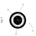
- FIG. 5 shows an end view of a pulverized coal burner in accordance with an embodiment of the invention.
- the burner cross-section 500 is annular-shaped defined by a coal pipe 502 and a coaxially positioned core pipe 506 with a liner 504 adjacent to an inner portion of the coal pipe 502.
- An outer diameter (do) of the cross-section 500 similar to the outer diameter (do) in Figures 2 and 3 , is defined by a distance between at least two inner portions of the coal pipe 502, and an inner diameter (di) of the cross-section 500, similar to the inner diameter (di) in Figures 2 and 3 , is defined by a distance between at least two outer portions of the core pipe 506.
- a liner diameter (dl) is defined by a distance between at least two inner portions of the liner 504.
- the core pipe 506 may be absent from the arrangement, and thus the coal pipe 502 would be coreless.
- the cross-section would have a similar outer diameter (do) as the outer diameter (do) in Figure 3 , but the inner diameter (di) would be zero.
- an ideal velocity V2 of a fuel mixture within the coal pipe 404, 604, or at the upstream end may differ from an ideal velocity V1, Vexit at the burner end adjacent to the ignitor and flame region 606, or at the downstream end 406, due to opposing requirements.
- a relatively high fuel mixture velocity in the coal pipe 404, 604 can help prevent or otherwise minimize coal or other fuel particulate from "falling out of the air" and clogging the coal pipe 404, 604.
- a relatively low fuel mixture velocity at a downstream end adjacent burner exit 606 may be needed to control flame instability, and to reduce the generation of nitrogen oxides (NOx).
- the velocities V1, V2 of the fuel mixture within the coal pipe 404 is typically determined by the flow rate, the flow temperature, and the cross-sectional area within the coal pipe 404.
- injection flow rate and flow temperature are usually fixed. Therefore, the flow area multiplied by the flow velocity is maintained relatively constant.
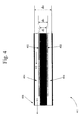
- Figures 4 and 6 illustrate respective side views of an example pulverized coal burner 400, 600 in accordance with an embodiment of the invention. If a sleeve 402, 602 is installed in a portion of the coal pipe 404, 604, the cross-section 200 of the coal pipe 404, 604 can be defined by an annulus with an outer diameter (do) and an inner (sleeve) diameter (ds), as depicted in Figure 2 .
- the cross-section 300 of the coal pipe 404, 604 can be defined by an annulus with an outer diameter (do) and an inner diameter (di), where the inner diameter (di) is typically defined by the outer diameter of the core pipe 304, as depicted in Figure 3 .
- the radial thickness of the sleeve 402 needed to produce a target velocity V2 within an upstream portion or end 406 of the coal pipe 404 can be calculated using the following equations (1), (2), and (3).
- Thickness Sleeve ds - di 2
- V1 50 ft/s (15.2 m/s)
- V2 60 ft/s (18.3 m/s)
- do 20 inches (50.8 cm)
- di 10 inches (25.4 cm).
- a sleeve diameter (ds) can be calculated to be approximately 12.25 inches (31.1 cm).
- a sleeve thickness calculated from equation (3) can be calculated to be approximately 1.125 inches (2.86 cm).
- Embodiments of the invention can include any combination of at least one sleeve and/or at least one liner.
- a sleeve 602 is mounted to and surrounds the core pipe 608.
- Figure 7 shows an example coal burner 700 with a liner 702 mounted to the interior portion of the coal pipe 704. Any number of embodiments can exist where the fuel mixture velocity is controlled or otherwise affected by any combination of liner and/or sleeve pieces, sections, or components.
- a sleeve and/or liner can be installed between the inner portion of the coal pipe 604, 704 and the outer portion of the core pipe 608, 708, and close proximity to or otherwise in contact with either or both.
- the relative exit velocity (Vexit) can be reduced, thereby reducing or minimizing flow recirculation and turbulence of the fuel mixture at the downstream end 606, 706 of the burner 600, 700, which can stabilize burner combustion characteristics, i.e., the burner flame.
- the sleeve and/or liner abruptly ends, for example, within approximately 6 inches (15.2 cm) of the downstream end 606, 706 of the burner 600, 700, a relatively higher probability may exist that unwanted turbulence will be generated near or adjacent to the downstream end 606, 706 of the burner 600, 700, thereby resulting in possible flow recirculation and/or flame instability.
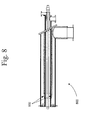
- FIG 8 depicts an example transition ramp for a pulverized coal burner in accordance with an embodiment of the invention.
- at least one burner embodiment 800 includes a transition sleeve, liner, or ramp 802, as shown in Figure 8 .
- a transition ramp similar to 802 as shown in Figure 8 , can also be applied in a similar fashion to a liner, for example, the liner 702 for burner 700 of Figure 7 .
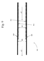
- FIG. 9 depicts a burner 900 with a coreless coal pipe and a liner 902 mounted adjacent to the inner portion of the coal pipe 904.
- a sleeve and/or liner can be installed in multiple corresponding and adjacent sections to accommodate existing obstructions that would otherwise prevent or hinder the installation of a single or single-piece sleeve and/or liner.
- one embodiment can include multiple sleeve pieces 1002, 1004, 1008 which can mount adjacent to the core pipe 1012 to accommodate any number of stabilizing or support members 1006 which may also mount to the core pipe 1012.
- a coal pipe is not shown in Figure 10 , but after the sleeve sections are installed, the outer coal pipe would coaxially mount to the splash plate 1010 to complete a burner assembly similar in structure to the burner 600 in Figure 6 .
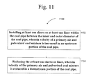
- Figure 11 illustrates an example method in accordance with an embodiment of the invention.
- Other method embodiments can include fewer or greater elements, and may have alternate arrangements in accordance with the invention.
- the method 1100 begins at block 1102, wherein at least one sleeve or at least one liner can be installed within the coal pipe between the inner and outer diameter of the coal pipe, wherein velocity of a primary air and pulverized coal mixture is increased in an upstream portion of the coal pipe.
- Block 1102 is followed by block 1104, wherein the at least one sleeve or liner can be reduced, wherein velocity of the primary air and pulverized coal mixture is reduced in a downstream portion of the coal pipe.
- the method 1100 ends at block 1104.
Landscapes
- Engineering & Computer Science (AREA)
- Chemical & Material Sciences (AREA)
- Mechanical Engineering (AREA)
- General Engineering & Computer Science (AREA)
- Combustion & Propulsion (AREA)
- Manufacturing & Machinery (AREA)
- Materials Engineering (AREA)
- Metallurgy (AREA)
- Organic Chemistry (AREA)
Abstract
Embodiments of the invention can include systems and methods for facilitating varying coal pipes for a pulverized coal burner. In one embodiment, a method for improving operation of a pulverized coal burner (600) is characterised by at least one coal pipe (604) having an inner diameter (608), and an outer diameter (604). The method can include installing at least one sleeve (602) or at least one liner within the coal pipe (604) between the inner (608) and outer diameter of the coal pipe (604), wherein velocity of a primary air and pulverized coal mixture is increased in an upstream portion of the coal pipe. The method can also include reducing the at least one sleeve (602) or liner, wherein velocity (Vexit) of the primary air and pulverized coal mixture is reduced in a downstream portion of the coal pipe.
Description
- The invention generally relates to pulverized coal burners, and more particularly relates to systems and methods for facilitating varying size coal pipes for a pulverized coal burner.
- Pulverized coal burners are utilized in combustion and heat transfer processes within utility and industrial boiler furnaces of coal-fired power plants and other power generating facilities. In a typical furnace, raw coal is crushed into small pieces, conveyed to coal feed hoppers, pulverized into a very fine powder, mixed with primary air, and blown through a furnace coal pipe, wherein the fine coal is directed to a coal burner where the mixture of primary air and coal is ignited upon introduction to the furnace. The subsequent combustion of the primary air and coal mixture heats the furnace to generate steam used for power generation and other plant purposes.
- Extracting maximum energy from pulverized coal while minimizing environmental pollutants sometimes requires careful control of the fuel delivery and combustion process. Excess nitrogen oxides (NOx) can be produced at the burner when the flame is not carefully controlled, or when it becomes unstable, as is often the case when the air/coal mixture velocity is too high when introduced at the burner end. However, the air/coal mixture velocity must be high enough within the coal delivery pipe so that the coal particles do not fall out of the air and collect in or otherwise clog the coal delivery pipe. These two opposing requirements (high air/coal mixture velocity in the coal delivery pipe and low air/coal mixture velocity at the burner end) present a difficult challenge for boiler and service engineers, particularly as furnace output and/or air/coal mixture velocity requirements change.
- Many existing pulverized coal burners were designed with coal pipe geometries tuned to a certain air/fuel injection and velocity rate. As new industrial pollution limits, process refinements, etc. are implemented, existing pulverized coal burners may not be suitable to maintain or otherwise attain certain upstream and downstream air/coal mixture velocity requirements, and new coal burner components, such as different sized coal delivery pipes, may need to be installed to stabilize the burner flame and eliminate coal dropout. Such installations can be time consuming and expensive.
- Therefore, a need exists for systems, methods, and apparatus for facilitating varying size coal pipes for a pulverized coal burner.
- A further need exists for systems, methods, and apparatus to modify or retrofit existing coal pipes as injection speeds or other system parameters are changed to meet new requirements.
- A further need exists for systems, methods, and apparatus for improving operation of a pulverized coal burner.
- Embodiments of the invention can include systems and methods for facilitating varying size coal pipes for a pulverized coal burner. Other embodiments of systems, apparatuses and methods for improving the operation of a pulverized a coal burner can also be provided. Certain embodiments of the invention can utilize existing parts of a coal pipe together with newly added sleeves, liners and/or transition ramps to meet target air/coal mixture velocities within the coal pipe and at the burner without having to replace the entire coal pipe assembly.
- In one embodiment, a method for improving operation of a pulverized coal burner can include at least one coal pipe having an inner diameter, and an outer diameter. In addition, the method can include installing at least one sleeve or at least one liner within the coal pipe between the inner and outer diameter of the coal pipe, wherein velocity of a primary air and pulverized coal mixture is increased in an upstream portion of the coal pipe. The method can also include reducing the at least one sleeve or liner, wherein velocity of the primary air and pulverized coal mixture is reduced in a downstream portion of the coal pipe.
- In one embodiment, an apparatus for improving operation of a pulverized coal burner can include at least one coal pipe having an inner diameter, and an outer diameter. The method can include installing at least one sleeve or at least one liner within the coal pipe between the inner and outer diameter of the coal pipe, wherein velocity of a primary air and pulverized coal mixture is increased in an upstream portion of the coal pipe. The method can also include reducing the at least one sleeve or at least one liner, wherein velocity of the primary air and pulverized coal mixture is reduced in a downstream portion of the coal pipe.
- In one embodiment, a combustion system can be provided. The combustion system can include at least one burner starter, at least one core pipe, wherein the at least one burner starter is mounted within at least one core pipe. The system can include at least one coal pipe having an inner diameter and an outer diameter. The system can further include at least one sleeve or at least one liner between the coal pipe inner diameter and outer diameter, wherein the velocity of a primary air and pulverized coal mixture is increased in an upstream portion of the coal pipe, and wherein velocity of the primary air and pulverized coal mixture is reduced in a downstream portion of the coal pipe.
- Other embodiments and aspects of embodiments of the invention will become apparent from the following description taken in conjunction with the accompanying drawings.
- Having thus described the invention in general terms, reference will now be made to the accompanying drawings, which are not necessarily drawn to scale, and wherein:
-
Figure 1 depicts an example of a conventional pulverized coal burner. -
Figure 2 shows an end view of an example pulverized coal burner in accordance with an embodiment of the invention. -
Figure 3 shows an end view of an example pulverized coal burner in accordance with an embodiment of the invention. -
Figure 4 shows a side view of an example pulverized coal burner in accordance with an embodiment of the invention. -
Figure 5 shows an end view of an example pulverized coal burner in accordance with an embodiment of the invention. -
Figure 6 illustrates a sleeve embodiment of the example pulverized coal burner shown inFigure 2 in accordance with an embodiment of the invention -
Figure 7 illustrates a liner embodiment of the example pulverized coal burner shown inFigure 5 in accordance with an embodiment of the invention. -
Figure 8 depicts an example transition ramp for a pulverized coal burner in accordance with an embodiment of the invention. -
Figure 9 depicts an embodiment of a pulverized coal burner in accordance with an embodiment of the invention. -
Figure 10 illustrates an example apparatus and system for facilitating varying coal pipes for a pulverized coal burner. -
Figure 11 illustrates an example method in accordance with an embodiment of the invention. - Embodiments of the invention will now be described more fully hereinafter with reference to the accompanying drawings. This invention may, however be embodied in many different forms and should not be construed as limited to the embodiment set forth herein; rather, embodiments are provided so that this disclosure will be thorough and complete, and will convey the scope of the invention.
- As used herein, the term "sleeve" refers to a structure that is adjacent to, borders, surrounds, mounts to, or is otherwise attached to an outer portion of a core pipe, such as 112 in
Figure 1 . One example of a sleeve is shown as 206 in thecross-section 200 ofFigure 2 , and can include a sleeve diameter (ds). In some embodiments, a sleeve may be a single piece or comprised of multiple pieces. - As used herein, the term "liner" refers to a structure that is adjacent to, borders, mounts to, or is otherwise attached to an inner portion of a coal pipe, such as 104 in
Figure 1 . One example of a liner is shown as 504 inFigure 5 and 702 inFigure 7 , and can include a liner inside diameter (dl). In some embodiments, a liner may be a single piece or comprised of multiple pieces. - As used herein, the term "fuel mixture" refers to a mixture of primary air and pulverized coal. Other embodiments may include mixtures of primary air and other fuel types.
- As used herein, the term "upstream" refers to a section of a coal pipe nearest to an inlet duct, such as 110 in
Figure 1 , and the term "downstream" refers to a section of a coal pipe nearest to an ignitor and flame end, such as 114 inFigure 1 , where a fuel mixture exits the coal pipe, such as 104 inFigure 1 . -
Figure 1 depicts an example of a conventional pulverized coal burner. The pulverizedcoal burner 100 is configured with aflame stabilizer 102 at a downstream end of acoal pipe 104, and asplash plate 106 at an opposing or upstream end of thecoal pipe 104. The pulverizedcoal burner 100 also includes a mounted gas gun andtube assembly 108, aninlet duct 110, and acore pipe 112. The gas gun andtube assembly 108 is coaxially mounted inside acore pipe 112, and both the gas gun andtube assembly 108 andcore pipe 112 are coaxially mounted within thecoal pipe 104. A mixture of primary air and pulverized coal, or fuel mixture, enters theburner 100 through theinlet duct 110 adjacent to the upstream end of theburner 100. Thesplash plate 106 helps re-direct the primary air and pulverized coal mixture, or fuel mixture, through thecoal pipe 104 towards the downstream end of theburner 100, through theflame stabilizer 102 adjacent to the downstream end, and to the ignitor andflame region 114, which is typically adjacent to a furnace. - Embodiments of a pulverized coal burner in accordance with the invention are shown with respect to
Figures 2 - 11 . Certain embodiments of the invention can provide improvements in the operation of a pulverized coal burner. In one such embodiment, one or more sleeves and/or liners can be installed within an associated coal pipe to increase velocity of the primary air /pulverized coal mixture, or fuel mixture, in an upstream portion of the coal pipe while simultaneously reducing velocity of the fuel mixture at an opposing end or downstream end of the coal pipe. The increased velocity at the upstream portion of the coal pipe tends to reduce coal dropout, while the reduced velocity at the downstream end tends to improve flame stability and can suppress excess production of nitrogen oxides (NOx). - To illustrate example principles for improving operation of a pulverized coal burner in accordance with embodiments of the invention,
Figures 2 - 5 illustrate certain geometries associated with components of various pulverized coal burners in accordance with embodiments of the invention. -
Figure 2 shows an end view of a pulverized coal burner in accordance with an embodiment of the invention. Theburner cross-section 200 is annular-shaped and defined by acoal pipe 202 and a coaxially positionedcore pipe 204 with asleeve 206 adjacent to an outer portion of thecore pipe 204. An outer diameter (do) of thecross-section 200 is defined by a distance between at least two inner portions of thecoal pipe 202, and an inner diameter (di) of the cross-section is defined by a distance between at least two outer portions of thecore pipe 204. A sleeve diameter (ds) is defined by a distance between at least two outer portions of thesleeve 206. -
Figure 3 shows an end view of a pulverized coal burner in accordance with an embodiment of the invention.Figure 3 represents reducing the at least one sleeve or liner, wherein velocity of the primary air and pulverized coal mixture is reduced in a downstream portion of the coal pipe. The term "reducing" can mean removing, omitting, or making less thick, and therefore, reducing the sleeve or liner in a portion of the coal pipe increases the volume of the coal pipe and reduces the velocity of the primary air and pulverized coal mixture in that section of the coal pipe. Theburner cross-section 300 is annular-shaped defined by acoal pipe 302 and a coaxially positionedcore pipe 304. An outer diameter (do) of thecross-section 300, similar to the outer diameter (do) inFigure 2 , is defined by a distance between at least two inner portions of thecoal pipe 302, and an inner diameter (di) of thecross-section 300, similar to the inner diameter (di) inFigure 2 , is defined by a distance between at least two outer portions of thecore pipe 304. -
Figure 5 shows an end view of a pulverized coal burner in accordance with an embodiment of the invention. Theburner cross-section 500 is annular-shaped defined by acoal pipe 502 and a coaxially positionedcore pipe 506 with aliner 504 adjacent to an inner portion of thecoal pipe 502. An outer diameter (do) of thecross-section 500, similar to the outer diameter (do) inFigures 2 and3 , is defined by a distance between at least two inner portions of thecoal pipe 502, and an inner diameter (di) of thecross-section 500, similar to the inner diameter (di) inFigures 2 and3 , is defined by a distance between at least two outer portions of thecore pipe 506. A liner diameter (dl) is defined by a distance between at least two inner portions of theliner 504. In one embodiment, thecore pipe 506 may be absent from the arrangement, and thus thecoal pipe 502 would be coreless. In that embodiment, the cross-section would have a similar outer diameter (do) as the outer diameter (do) inFigure 3 , but the inner diameter (di) would be zero. - Referring to
Figures 4 and6 , an ideal velocity V2 of a fuel mixture within thecoal pipe flame region 606, or at thedownstream end 406, due to opposing requirements. For example, a relatively high fuel mixture velocity in thecoal pipe coal pipe adjacent burner exit 606 may be needed to control flame instability, and to reduce the generation of nitrogen oxides (NOx). - The velocities V1, V2 of the fuel mixture within the
coal pipe 404 is typically determined by the flow rate, the flow temperature, and the cross-sectional area within thecoal pipe 404. For a pulverized coal burner in accordance with embodiments of the invention, injection flow rate and flow temperature are usually fixed. Therefore, the flow area multiplied by the flow velocity is maintained relatively constant. -
Figures 4 and6 illustrate respective side views of an example pulverizedcoal burner sleeve coal pipe cross-section 200 of thecoal pipe Figure 2 . Towards thedownstream end burner sleeve cross-section 300 of thecoal pipe core pipe 304, as depicted inFigure 3 . - With reference to
Figure 4 , given a target exit velocity V1, the radial thickness of thesleeve 402 needed to produce a target velocity V2 within an upstream portion or end 406 of thecoal pipe 404 can be calculated using the following equations (1), (2), and (3).


- In one example, V1 = 50 ft/s (15.2 m/s), V2 = 60 ft/s (18.3 m/s), do = 20 inches (50.8 cm), di = 10 inches (25.4 cm). From equation (2), a sleeve diameter (ds) can be calculated to be approximately 12.25 inches (31.1 cm). A sleeve thickness calculated from equation (3) can be calculated to be approximately 1.125 inches (2.86 cm). Using some or all of the equations (1), (2), and (3), one can perform a similar calculation to determine geometric requirements for a liner embodiment, as shown in
Figures 5 and7 . - Embodiments of the invention can include any combination of at least one sleeve and/or at least one liner. In the example pulverized
coal burner 600 shown inFigure 6 , asleeve 602 is mounted to and surrounds thecore pipe 608.Figure 7 , in contrast, shows anexample coal burner 700 with aliner 702 mounted to the interior portion of thecoal pipe 704. Any number of embodiments can exist where the fuel mixture velocity is controlled or otherwise affected by any combination of liner and/or sleeve pieces, sections, or components. Depending on flow conditions within the associatedcoal pipe coal pipe core pipe - In this manner, the relative exit velocity (Vexit) can be reduced, thereby reducing or minimizing flow recirculation and turbulence of the fuel mixture at the
downstream end burner downstream end burner downstream end burner -
Figure 8 depicts an example transition ramp for a pulverized coal burner in accordance with an embodiment of the invention. To minimize or otherwise reduce turbulence generated near or adjacent to an downstream end of a burner, at least oneburner embodiment 800 includes a transition sleeve, liner, orramp 802, as shown inFigure 8 . In this manner, turbulence caused by velocity discontinuities in the coal pipe can be minimized. In one embodiment, a transition ramp, similar to 802 as shown inFigure 8 , can also be applied in a similar fashion to a liner, for example, theliner 702 forburner 700 ofFigure 7 . - One pulverized coal burner embodiment is described by way of
Figure 9 , which depicts aburner 900 with a coreless coal pipe and aliner 902 mounted adjacent to the inner portion of thecoal pipe 904. In this embodiment, the respective fuel mixture upstream and exit velocities, V1 and V2, are related to the respective coal pipe and liner diameters, do and dl, by the equation:
where again, a transition ramp element or feature, similar to 802 ofFigure 8 , may be applied to theliner 902 shown to reduce or otherwise minimize turbulence and flow recirculation. - In one embodiment, a sleeve and/or liner can be installed in multiple corresponding and adjacent sections to accommodate existing obstructions that would otherwise prevent or hinder the installation of a single or single-piece sleeve and/or liner. As shown in
Figure 10 , one embodiment can includemultiple sleeve pieces core pipe 1012 to accommodate any number of stabilizing orsupport members 1006 which may also mount to thecore pipe 1012. Note that a coal pipe is not shown inFigure 10 , but after the sleeve sections are installed, the outer coal pipe would coaxially mount to thesplash plate 1010 to complete a burner assembly similar in structure to theburner 600 inFigure 6 . -
Figure 11 illustrates an example method in accordance with an embodiment of the invention. Other method embodiments can include fewer or greater elements, and may have alternate arrangements in accordance with the invention. - The
method 1100 begins atblock 1102, wherein at least one sleeve or at least one liner can be installed within the coal pipe between the inner and outer diameter of the coal pipe, wherein velocity of a primary air and pulverized coal mixture is increased in an upstream portion of the coal pipe. -
Block 1102 is followed byblock 1104, wherein the at least one sleeve or liner can be reduced, wherein velocity of the primary air and pulverized coal mixture is reduced in a downstream portion of the coal pipe. - The
method 1100 ends atblock 1104. - The methods, systems and apparatus disclosed herein are by way of example only, and other methods in accordance with the embodiments of the invention can include other elements or steps, including fewer or greater numbers of elements or steps than the example methods described herein as well as various combinations of these or other elements.
- While the above description contains many specifics, these specifics should not be construed as limitations on the scope of the invention, but merely as exemplifications of the disclosed embodiments. Those skilled in the art will envision many other possible variations that are within the scope of the invention.
- Various aspects and embodiments of the present invention are defined by the following numbered clauses:
- 1. A method for improving operation of a pulverized coal burner comprising at least one coal pipe having an inner diameter, and an outer diameter, the method comprising:
- installing at least one sleeve or at least one liner within the coal pipe between the inner and outer diameter of the coal pipe, wherein velocity of a primary air and pulverized coal mixture is increased in an upstream portion of the coal pipe; and
- reducing the at least one sleeve or liner, wherein velocity of the primary air and pulverized coal mixture is reduced in a downstream portion of the coal pipe.
- 2. The method of Clause 1, wherein the at least one sleeve or at least one liner terminates within about 10 to about 20 inches (25.4 to 50.8 cm) from a downstream end of the burner.
- 3. The method of any preceding clause, wherein the at least one sleeve or at least one liner comprises a ceramic, metal, or a high temperature resistant material.
- 4. The method of any preceding clause, wherein the at least one sleeve or at least one liner comprises at least one transition ramp or device to prevent flow recirculation.
- 5. The method of any preceding clause, wherein the at least one sleeve or at least one liner comprises a plurality of sleeve or liner components or sections.
- 6. The method of any preceding clause, wherein a thickness of the at least one sleeve or at least one liner is determined by the equations:


wherein, ds is an outer diameter of the at least one sleeve, do is an outer diameter of the coal pipe, di is an inner diameter of the coal pipe, V2 is a target velocity of the primary air and pulverized coal mixture within the upstream portion of the coal pipe, and V1 is a target exit velocity of the primary air and pulverized coal mixture. - 7. The method of any preceding clause, wherein the at least one sleeve or at least one liner is mounted coaxially and in close proximity to an inner diameter, of at least one coal pipe, or coaxially and in close proximity to an outer diameter, of the at least one coal pipe.
- 8. An apparatus for improving operation of a pulverized coal burner comprising at least one coal pipe having an inner diameter, and an outer diameter, the apparatus comprising:
- at least one sleeve or at least one liner installed within the coal pipe between the inner and outer diameter of the coal pipe, wherein velocity of a primary air and pulverized coal mixture is increased in an upstream portion of the coal pipe; and
- wherein the at least one sleeve or at least one liner is reduced in a downstream portion of the coal pipe to reduce the velocity of the primary air and pulverized coal mixture.
- 9. The apparatus of Clause 8, wherein the at least one sleeve or at least one liner terminates within about 10 to about 20 inches (25.4 to 50.8 cm) from a downstream end of the burner.
- 10. The apparatus of
Clause 8 or 9, wherein the at least one sleeve or at least one liner comprises a ceramic, a metal, or a high temperature resistant material. - 11. The apparatus of any of clauses 8 to 10, wherein the at least one sleeve or at least one liner comprises at least one transition ramp or device to prevent flow recirculation.
- 12. The apparatus of any of clauses 8 to 11, wherein the at least one sleeve or at least one liner comprises a plurality of sleeve or liner components or sections.
- 13. The apparatus of any of clauses 8 to 12, wherein a thickness of the at least one sleeve or at least one liner is determined by the equations:


wherein, ds is an outer diameter of the at least one sleeve, do is an outer diameter of the coal pipe, di is an inner diameter of the coal pipe, V2 is a target velocity of the primary air and pulverized coal mixture within the coal pipe, and V1 is a target exit velocity of the primary air and pulverized coal mixture. - 14. A combustion system comprising:
- at least one burner starter;
- at least one core pipe, wherein the at least one burner starter is mounted within at least one core pipe;
- at least one coal pipe having an inner diameter and an outer diameter;
- at least one sleeve or at least one liner between the coal pipe inner diameter, and outer diameter, wherein the velocity of a primary air and pulverized coal mixture is increased in an upstream portion of the coal pipe, and wherein velocity of the primary air and pulverized coal mixture is reduced in a downstream portion of the coal pipe.
- 15. The system of Clause 14, wherein the at least one sleeve or at least one liner terminates within about 10 to about 20 inches (25.4 to 50.8 cm) from a downstream end of the burner.
- 16. The system of Clause 14 or 15, wherein the at least one sleeve or at least one liner comprises a ceramic, metal, or a high temperature resistant material.
- 17. The system of any of Clauses 14 to 16, wherein the at least one sleeve or at least one liner comprises at least one transition ramp or device to prevent flow recirculation.
- 18. The system of any of Clauses 14 to 17, wherein the at least one sleeve or at least one liner comprises a plurality of sleeve or liner components or sections.
- 19. The system of any of Clauses 14 to 18, wherein a thickness of the at least one sleeve or at least one liner is determined by the equations:


wherein, ds is an outer diameter of the at least one sleeve, do is an outer diameter of the coal pipe, di is an inner diameter of the coal pipe, V2 is a target velocity of the primary air and pulverized coal mixture within the coal pipe, and V1 is a target exit velocity of the primary air and pulverized coal mixture at the burner. - 20. The system of any of Clauses 14 to 19, wherein the at least one sleeve or at least one liner is mounted coaxially and in close proximity to an outer diameter, of the at least one coal pipe, or coaxially and in close proximity to an inner diameter, of the at least one coal pipe.
Claims (10)
- A method for improving operation of a pulverized coal burner (100) characterised by at least one coal pipe (604) having an inner diameter (204), and an outer diameter (202), the method characterised by:installing at least one sleeve (602) or at least one liner (702) within the coal pipe between the inner (304) and outer (302) diameter of the coal pipe (604), wherein velocity of a primary air and pulverized coal mixture is increased in an upstream portion of the coal pipe (604); andreducing the at least one sleeve (602) or liner (702), wherein velocity of the primary air and pulverized coal mixture is reduced in a downstream portion of the coal pipe (604).
- The method of claim 1, wherein the at least one sleeve (602) or at least one liner (702) terminates within about 10 to about 20 inches (25.4 to 50.8 cm) from a downstream end (606) of the burner.
- The method of any preceding claim, wherein the at least one sleeve (602) or at least one liner (702) is characterised by a ceramic, metal, or a high temperature resistant material.
- The method of any preceding claim, wherein the at least one sleeve (602) or at least one liner (702) is characterised by at least one transition ramp (802) or device to prevent flow recirculation.
- The method of any preceding claim, wherein the at least one sleeve (602) or at least one liner (702) is characterised by a plurality of sleeve or liner components or sections (1004).
- The method of any preceding claim, wherein a thickness of the at least one sleeve (602) or at least one liner (702) is determined by the equations:


wherein, ds is an outer diameter of the at least one sleeve (602), do is an outer diameter of the coal pipe (302), di is an inner diameter of the coal pipe (304), V2 is a target velocity of the primary air and pulverized coal mixture within the upstream portion of the coal pipe (404), and V1 is a target exit (406) velocity of the primary air and pulverized coal mixture. - The method of any preceding claim, wherein the at least one sleeve (206) or at least one liner (504) is mounted coaxially and in close proximity to an inner diameter (204), of at least one coal pipe, or coaxially and in close proximity to an outer diameter (202), of the at least one coal pipe.
- An apparatus for improving operation of a pulverized coal burner (100) characterised by at least one coal pipe (604) having an inner diameter (204), and an outer diameter (202), the apparatus characterised by:at least one sleeve (206) or at least one liner (504) installed within the coal pipe (604) between the inner (204) and outer (202) diameter of the coal pipe (604), wherein velocity of a primary air and pulverized coal mixture is increased in an upstream portion of the coal pipe (604); andwherein the at least one sleeve (602) or at least one liner (702) is reduced in a downstream portion of the coal pipe (604) to reduce the velocity (Vexit) of the primary air and pulverized coal mixture.
- The apparatus of claim 8, wherein the at least one sleeve (602) or at least one liner (702) is characterized by at least one transition ramp (802) or device to prevent flow recirculation.
- A combustion system characterised by at least one burner starter (114) and further characterised by:at least one core pipe (104), wherein the at least one burner starter (108, 114) is mounted within at least one core pipe (112);at least one coal pipe (604) having an inner diameter (304) and an outer diameter (302); at least one sleeve (602) or at least one liner (702) between the coal pipe inner diameter (304), and outer diameter (302), wherein the velocity of a primary air and pulverized coal mixture is increased in an upstream portion of the coal pipe, and wherein velocity of the primary air and pulverized coal mixture is reduced in a downstream portion of the coal pipe.
Applications Claiming Priority (1)
| Application Number | Priority Date | Filing Date | Title |
|---|---|---|---|
| US12/241,623 US20100081102A1 (en) | 2008-09-30 | 2008-09-30 | Systems and methods for facilitating varying size coal pipes for a pulverized coal burner |
Publications (1)
| Publication Number | Publication Date |
|---|---|
| EP2169306A1 true EP2169306A1 (en) | 2010-03-31 |
Family
ID=41429154
Family Applications (1)
| Application Number | Title | Priority Date | Filing Date |
|---|---|---|---|
| EP09171043A Withdrawn EP2169306A1 (en) | 2008-09-30 | 2009-09-23 | Systems and methods for facilitating varying size coal pipes for a pulverized coal burner |
Country Status (4)
| Country | Link |
|---|---|
| US (1) | US20100081102A1 (en) |
| EP (1) | EP2169306A1 (en) |
| CN (1) | CN101713537A (en) |
| CA (1) | CA2680624A1 (en) |
Families Citing this family (5)
| Publication number | Priority date | Publication date | Assignee | Title |
|---|---|---|---|---|
| CN106931789A (en) * | 2015-12-30 | 2017-07-07 | 江西瑞林稀贵金属科技有限公司 | top-blown spray gun |
| CN108413387B (en) * | 2018-03-09 | 2019-09-24 | 山西大学 | A kind of two-way double grading combustion technologies of pulverized-coal fired boiler |
| JP7600820B2 (en) | 2021-03-30 | 2024-12-17 | 株式会社Ihi | Powdered fuel burners |
| CN112923358B (en) * | 2021-04-07 | 2025-02-18 | 南京建安机械制造有限公司 | Low nitrogen supersonic energy-saving automatic adjustment six-air duct pulverized coal burner |
| CN114923168B (en) * | 2022-05-17 | 2022-12-02 | 哈尔滨工业大学 | Self-stable combustion low-nitrogen oxide four-corner tangential boiler and combustion method |
Citations (6)
| Publication number | Priority date | Publication date | Assignee | Title |
|---|---|---|---|---|
| JPS62172105A (en) * | 1986-01-24 | 1987-07-29 | Hitachi Ltd | Combustion method and device for preventing production of nox |
| US4951581A (en) * | 1989-06-21 | 1990-08-28 | Aptec, Inc. | Combined oil gun and coal guide for power plant boilers |
| US5231937A (en) | 1990-03-07 | 1993-08-03 | Hitachi, Ltd. | Pulverized coal burner, pulverized coal boiler and method of burning pulverized coal |
| US5762007A (en) * | 1996-12-23 | 1998-06-09 | Vatsky; Joel | Fuel injector for use in a furnace |
| US6237510B1 (en) * | 1996-07-19 | 2001-05-29 | Babcock-Hitachi Kabushiki Kaisha | Combustion burner and combustion device provided with same |
| JP2003222310A (en) * | 2002-01-31 | 2003-08-08 | Babcock Hitachi Kk | Combustion device and method of biomass fuel |
Family Cites Families (7)
| Publication number | Priority date | Publication date | Assignee | Title |
|---|---|---|---|---|
| US4274587A (en) * | 1979-01-22 | 1981-06-23 | Electric Power Research Institute, Inc. | Water cooled burner nozzle for solvent refined coal |
| US4457241A (en) * | 1981-12-23 | 1984-07-03 | Riley Stoker Corporation | Method of burning pulverized coal |
| US4633913A (en) * | 1983-09-26 | 1987-01-06 | Combustion Engineering, Inc. | Wear-resistant pipe |
| US5387472A (en) * | 1992-05-20 | 1995-02-07 | Nelson Metal Products Corporation | Mated molded parts assembly and method for making same |
| DE19527083A1 (en) * | 1995-07-25 | 1997-01-30 | Lentjes Kraftwerkstechnik | Process and burner for reducing NO¶x¶ formation from coal dust combustion |
| JP3099109B2 (en) * | 1996-05-24 | 2000-10-16 | 株式会社日立製作所 | Pulverized coal burner |
| JPH09318014A (en) * | 1996-05-27 | 1997-12-12 | Hitachi Ltd | Pulverized coal combustion burner |
-
2008
- 2008-09-30 US US12/241,623 patent/US20100081102A1/en not_active Abandoned
-
2009
- 2009-09-23 EP EP09171043A patent/EP2169306A1/en not_active Withdrawn
- 2009-09-24 CA CA2680624A patent/CA2680624A1/en not_active Abandoned
- 2009-09-30 CN CN200910205214A patent/CN101713537A/en active Pending
Patent Citations (6)
| Publication number | Priority date | Publication date | Assignee | Title |
|---|---|---|---|---|
| JPS62172105A (en) * | 1986-01-24 | 1987-07-29 | Hitachi Ltd | Combustion method and device for preventing production of nox |
| US4951581A (en) * | 1989-06-21 | 1990-08-28 | Aptec, Inc. | Combined oil gun and coal guide for power plant boilers |
| US5231937A (en) | 1990-03-07 | 1993-08-03 | Hitachi, Ltd. | Pulverized coal burner, pulverized coal boiler and method of burning pulverized coal |
| US6237510B1 (en) * | 1996-07-19 | 2001-05-29 | Babcock-Hitachi Kabushiki Kaisha | Combustion burner and combustion device provided with same |
| US5762007A (en) * | 1996-12-23 | 1998-06-09 | Vatsky; Joel | Fuel injector for use in a furnace |
| JP2003222310A (en) * | 2002-01-31 | 2003-08-08 | Babcock Hitachi Kk | Combustion device and method of biomass fuel |
Also Published As
| Publication number | Publication date |
|---|---|
| CN101713537A (en) | 2010-05-26 |
| US20100081102A1 (en) | 2010-04-01 |
| CA2680624A1 (en) | 2010-03-30 |
Similar Documents
| Publication | Publication Date | Title |
|---|---|---|
| EP0529779B1 (en) | Low NOx burners | |
| US5299930A (en) | Low nox burner | |
| EP2169306A1 (en) | Systems and methods for facilitating varying size coal pipes for a pulverized coal burner | |
| CA2410725A1 (en) | Solid fuel burner, burning method using the same, combustion apparatus and method of operating the combustion apparatus | |
| US5529000A (en) | Pulverized coal and air flow spreader | |
| EP2818797B1 (en) | Burner with flame stabilizing center air jet device for pulverized low quality fuel, coal e.g. | |
| CA1102229A (en) | Gas burner for flame adherence to tile surface | |
| EP1649219B1 (en) | Gas turbine burner | |
| GB2375601A (en) | Burner apparatus for reducing combustion vibrations | |
| CN109642728B (en) | System for increasing the concentration of pulverized fuel in the internal combustion chamber | |
| EP3469260A1 (en) | Burner | |
| EP1726877A1 (en) | Method and device for controlling injection of primary and secondary air in an incineration system | |
| US4043512A (en) | Coal burner | |
| JP2016109349A (en) | Solid fuel burner and boiler including solid fuel burner | |
| CN106568079B (en) | System and method for providing combustion in a boiler | |
| EP3645941B1 (en) | Burner with a combustion head with low emission of nox | |
| GB1585410A (en) | Burner | |
| EP3819540B1 (en) | Burner assembly, method for operating said burner assembly and plant comprising said burner assembly | |
| EP3819541B1 (en) | Burner assembly, method for operating said burner assembly and plant comprising said burner assembly | |
| WO2023204103A1 (en) | Powder fuel burner | |
| KR102343982B1 (en) | Solid Fuel Burners and Combustion Units | |
| RU2070687C1 (en) | Burner | |
| EP3438531A1 (en) | Coal nozzle with a flow constriction | |
| RU2289063C1 (en) | Plant for plasma lighting and stabilization of burning of coal-dust flame | |
| WO1992016793A1 (en) | Low nox emission burner |
Legal Events
| Date | Code | Title | Description |
|---|---|---|---|
| PUAI | Public reference made under article 153(3) epc to a published international application that has entered the european phase |
Free format text: ORIGINAL CODE: 0009012 |
|
| AK | Designated contracting states |
Kind code of ref document: A1 Designated state(s): AT BE BG CH CY CZ DE DK EE ES FI FR GB GR HR HU IE IS IT LI LT LU LV MC MK MT NL NO PL PT RO SE SI SK SM TR |
|
| AX | Request for extension of the european patent |
Extension state: AL BA RS |
|
| 17P | Request for examination filed |
Effective date: 20100930 |
|
| 17Q | First examination report despatched |
Effective date: 20101027 |
|
| STAA | Information on the status of an ep patent application or granted ep patent |
Free format text: STATUS: THE APPLICATION IS DEEMED TO BE WITHDRAWN |
|
| 18D | Application deemed to be withdrawn |
Effective date: 20140401 |